EP0536068B1 - Low orbit satellite communication system with terminals as destination - Google Patents
Low orbit satellite communication system with terminals as destinationDownload PDFInfo
- Publication number
- EP0536068B1 EP0536068B1EP19920420345EP92420345AEP0536068B1EP 0536068 B1EP0536068 B1EP 0536068B1EP 19920420345EP19920420345EP 19920420345EP 92420345 AEP92420345 AEP 92420345AEP 0536068 B1EP0536068 B1EP 0536068B1
- Authority
- EP
- European Patent Office
- Prior art keywords
- satellite
- terminal
- satellites
- terminals
- time
- Prior art date
- Legal status (The legal status is an assumption and is not a legal conclusion. Google has not performed a legal analysis and makes no representation as to the accuracy of the status listed.)
- Expired - Lifetime
Links
Images


Classifications
- H—ELECTRICITY
- H04—ELECTRIC COMMUNICATION TECHNIQUE
- H04B—TRANSMISSION
- H04B7/00—Radio transmission systems, i.e. using radiation field
- H04B7/14—Relay systems
- H04B7/15—Active relay systems
- H04B7/204—Multiple access
- H04B7/2041—Spot beam multiple access
Definitions
- the inventionrelates to a satellite communications system. in low orbit to mobile and non-mobile terminals, transceivers or receivers only.
- Satellite communications with mobile terminals studied so far used two types of orbitorbits of geostationary satellites or elliptical orbits strongly inclined both having the property of being located, in medium, above areas in space with high concentration of particles, called "Van Allen belts". Recently orbits lower were considered. Their altitude is between 800 and 2000 km.
- One of the characteristics of communication systems by satellites that use such orbitsis the possibility of communicate with a large number of mobile terminals, for example portable type. But the poor radio performance of these terminals make it necessary to provide for compensation obtained with superior radio performance of the satellite.
- the difference between the orbits of altitude higher than the "Van Allen belts" and those of lower altitudelies in a space attenuation the weaker the closer the satellite is to Earth.
- L bandFor these communications, depending on the frequency bands two transmission architectures are available.
- the firstuses L band only for links mobile-satellite, the other the L and S bands.
- these architecturesmay vary by country, since several transmission standards can be used: for example use of TDMA access techniques, use of CDMA type ....
- the communication system of the inventionis compatible with GSM standards ("mobile special group"). It is also adaptable to CDMA transmission techniques. This system uses only a band of frequencies for terminal-satellite links.
- the object of the inventionis therefore to propose a sequence of particular transmission, since both the satellite and the terminal cannot receive and transmit at the same time. This therefore requires the setting up a transmission / reception frame and having specific synchronization features, in time for a TDMA system, and in time and in code for a CDMA system.
- a CCIR reportentitled "Technical characteristics of a personnal communication mobile satellite system "describes a communications system by low orbit satellites with multibeam antennas; each comprising 37 conical beams.
- Such a systemhas the great disadvantage of having a large number of brushes which form, each one, a small trace on the ground.
- changes in brushescan occur over time. These are accompanied generally a change of resources (“hand-over").
- Their number high during a conversationis a harmful phenomenon the quality of the connection and the listening comfort.
- Such a systemhas for the disadvantage of having a long transmission-reception frame.
- the object of the present inventionis to overcome these disadvantages in describing a communication system that allows to significantly improve the capacity of satellites, by using a short transmit-receive frame.
- the payload proposed in this documentis complex because it includes means for demodulation, decoding, coding, remodulation, switching, volatile memories ("buffers" in English) multiplexing, reformatting and signal processing, and conversion of frequencies. In addition, it must convert uplinks multiplexed in TDMA to 44 GHZ, in downlink in TDMA with frequency hopping and brush hopping at 20 GHZ.
- the object of the inventionis to overcome these drawbacks by describing a communication system that allows, in a way simple, optimized use of the radio spectrum in a only frequency band that would be used for links up and down.
- the inventionproposes for this purpose a communications system by satellites in low orbit to terminals according to the claim 1, as well as the various equipment forming part of a such system and described in other claims.
- the antenna system of communication from each satelliteprovides isoflux coverage composed of several brushes which can advantageously be elliptical, elongated in the direction of travel of the satellite.
- the satellite system or "constellation" consideredis a global coverage system that complements systems existing terrestrial communications.
- a terminal mobile or not, transceiver or receiver onlyis identified, located and linked by a constellation satellite to through a connection station to the public fixed network him allowing access to all the services of the public network telephone or future ISDN.
- the radio resources allocated to all terminalsare divided into satellite cells which correspond each to an area of small radius relative to the coverage satellite and large radius with respect to a terrestrial cell of a "Groupe Spécial Mobiles" (GSM) mobile network.
- GSMGroupe Spécial Mobiles
- Each type of orbithas points of intersection with the planes orbit. In the case of polar orbits, the intersection zone of these are close to the poles. In the case of inclined orbits, this area is close to the equator.
- the service area of a satelliteis defined by a geometric condition: it is the set of points on the earth from where the satellite is seen with a elevation (angle that the user-satellite direction makes with the plane tangent to the earth at the terminal location) greater than one predetermined value (the practical value is between 10 ° and 15 °).
- Such a propertyis advantageous, because it makes it possible to establish communications with at least two satellites in most case.
- the design of the system according to the inventiontakes account of these multiple covers to avoid interference between covers.
- the mode of access to these satellites in low orbitalso depends account for this interference problem.
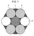
- a zone of cover using several brushes 10 as shown in the figure 1has several disadvantages: it has, in the satellite path to terminal, several areas in which the jamming powers are very important. These areas, both in TDMA (time division multiple access) than CDMA (access multiple with coding distribution), are dimensioning, i.e. that they participate very largely in size, weight and cost of the satellite considered. If the orbits are more inclined, these interference can lead to link breaks during several tens of seconds. In addition, such coverage using of fine paintbrushes requires fairly resource changes frequent. In a system where the number of brushes is large, this leads to a change of resource for example every minutes. The treatment load induced on the ground is therefore far from being negligible.
- the proximity effectcan be important, whether in AMRT / AMRF or in AMRF (access frequency distribution), where the harmful effect of carrying large amplitudes on those which are less powerful, it is desirable to have an antenna gain leading to the ground at a power received (per unit area) as uniform as possible.
- the satellite system of the inventionis a cellular system for which the larger cells, are formed by the trace at ground of the different brushes 12 covering each satellite 13 multi-beam.
- a cellis characterized by a set of resources (frequencies, intervals of time, codes), from which the terminal draws an element during establishing communication.
- the system according to the inventionis an N-brush system 12.
- Figure 2which represents the ground cover 14 of a satellite 13 of the contellation, we light up successively a group of several spots 12 chosen from among the N satellite spots sequentially. This operation is performed both in transmission and in reception, which naturally leads to a transmission frame.
- the coverageis consists of a set of N spots (which can be circular, elliptical or of any shape) lit simultaneously according to the "beam-hopping" law.
- Programs and receptions in different spotsare carried out in accordance with the diagram of satellite frames studied more far.
- modesusing either frequency separation of signals (AMRF), either a separation by time (TDMA), or a separation by code (CDMA), i.e. hybrid modes: a combination CDMA-TDMA by example.
- AMRFfrequency separation of signals
- TDMAseparation by time
- CDMAseparation by code
- the main problem with TDD accessis the initial acquisition transmission synchronization.
- This synchronizationis performed first in open loop then in closed loop using the station that controls the network.
- a terminalacquires the network signaling channel.
- if he has to transmitsend a first message whose reception allows define the time difference that should be applied to be perfectly synchronized.
- This synchronization in loopbeing made and the synchronized terminal, tracking and controlling this synchronization is obtained by measuring this synchronization made in the earth station interfacing with the networks switched telephone lines.
- the terminalhas a dual-frequency operation, but alternating. As soon as he receives a signal from the satellite, it transmits. On the satellite side, distance differences helping, it is not possible to receive all signals from terminals in a single brush simultaneously.
- the satellite programis screened with brushstroke, that is to say that it is done alternately by half the number of brushes, each emitting brush being separated from another by a non-emitting brush. At the next time step, it is the opposite.
- the reception of the satellitecan only be permanent due to the fact of the temporal dispersion resulting from the dispersion of the distances. Access in code is sensitive to the amplitude dispersion of different carriers at the same frequency.
- the only problem that can ariseis the transmission of a terminal a parity, at low elevation, during the reception of a terminal opposite parity located in the vicinity of the latter; But there are two remedies for this situation of which a probability calculation indicates the low frequency.
- the firstrelates to the allocation of resources by the same station. Indeed, the two terminals depend on principle of the same connection station, since they are close one the other.
- the resource allocation algorithmcan do so that even and odd terminals do not have access to the same channels, which in principle solves the problem for the vast majority operational situations.
- the secondis to perform a "hand-over" upon detection of persistent interference.
- the chosen frame structureseen from the satellite, therefore comprises two transmission-reception intervals, the transmission duration being equal to that of reception.
- the duration of a transmission intervalis equal to that of a GSM frame, i.e. 4.615 ms.
- the duration of the basic frameis of four GSM frames, but an operating mode with a duration double is possible, to take into account an operating mode at elevation less than 20 °.
- the structure of the GSM frameis therefore essential, since constraint by the altitude of the satellites.
- the organization (temporal arrangement) of the framescannot be kept as it is, at least in this operating mode at the work-study program.
- functionallyit is possible to have of the same types of channels, even if the numbering is changed.
- the frame rateis retained, as is the modulation and duration of packages. Signaling channels are kept at the identical. So at an additional delay, of a few milliseconds, the same procedures may apply.
Landscapes
- Engineering & Computer Science (AREA)
- Computer Networks & Wireless Communication (AREA)
- Signal Processing (AREA)
- Radio Relay Systems (AREA)
Description
Translated fromFrenchL'invention concerne un système de communications par satellitesen orbite basse à destination de terminaux mobiles ou non,émetteurs-récepteurs ou récepteurs uniquement.The invention relates to a satellite communications system.in low orbit to mobile and non-mobile terminals,transceivers or receivers only.
Les communications par satellites avec des terminaux mobilesétudiées jusqu'à présent utilisaient deux types d'orbites : lesorbites des satellites géostationnaires ou des orbites elliptiquesfortement inclinées ayant toutes deux la propriété d'être situées, enmoyenne, au dessus de zones dans l'espace à forte concentration departicules, appelées "ceintures de Van Allen". Depuis peu des orbitesplus basses ont été considérées. Leur altitude se situe entre 800 et2000 Km. Une des caractéristiques des systèmes de communications parsatellites qui utilisent de telles orbites est la possibilité decommuniquer avec un nombre important de terminaux mobiles, par exempledu type portatif. Mais les faibles performances radio-électriques deces terminaux obligent à prévoir une compensation obtenue avec desperformances radio-électriques supérieures du satellite. La différenceentre les orbites d'altitude supérieure aux "ceintures de Van Allen"et celles d'altitude inférieure réside dans une atténuation d'espaced'autant plus faible que le satellite est proche de la terre.Satellite communications with mobile terminalsstudied so far used two types of orbit:orbits of geostationary satellites or elliptical orbitsstrongly inclined both having the property of being located, inmedium, above areas in space with high concentration ofparticles, called "Van Allen belts". Recently orbitslower were considered. Their altitude is between 800 and2000 km. One of the characteristics of communication systems bysatellites that use such orbits is the possibility ofcommunicate with a large number of mobile terminals, for exampleportable type. But the poor radio performance ofthese terminals make it necessary to provide for compensation obtained withsuperior radio performance of the satellite. The differencebetween the orbits of altitude higher than the "Van Allen belts"and those of lower altitude lies in a space attenuationthe weaker the closer the satellite is to Earth.
Pour ces communications, suivant les bandes de fréquencesdisponibles, deux architectures de transmission sont possibles. Lapremière utilise la bande L uniquement pour les liaisonsmobile-satellite, l'autre les bandes L et S. Par ailleurs, cesarchitectures peuvent varier suivant les pays, puisque plusieursnormes de transmission peuvent être employées : par exempleutilisation de techniques d'accès AMRT, utilisation de techniques detype AMRC....For these communications, depending on the frequency bandstwo transmission architectures are available. Thefirst uses L band only for linksmobile-satellite, the other the L and S bands. Furthermore, thesearchitectures may vary by country, since severaltransmission standards can be used: for exampleuse of TDMA access techniques, use ofCDMA type ....
Le système de communications de l'invention est compatible desnormes GSM ("groupe spécial mobiles"). Il est également adaptable auxtechniques de transmission AMRC. Ce système n'utilise qu'une bande defréquences pour les liaisons terminal-satellite.The communication system of the invention is compatible withGSM standards ("mobile special group"). It is also adaptable toCDMA transmission techniques. This system uses only a band offrequencies for terminal-satellite links.
L'invention a donc pour objet de proposer une séquence detransmission particulière, puisque tant le satellite que le terminal ne peuvent recevoir et émettre en même temps. Cela oblige donc à lamise en place d'une trame émission/réception et à disposer defonctionnalités de synchronisation spécifiques, en temps pour unsystème AMRT, et en temps et en code pour un système AMRC.The object of the invention is therefore to propose a sequence ofparticular transmission, since both the satellite and the terminalcannot receive and transmit at the same time. This therefore requires thesetting up a transmission / reception frame and havingspecific synchronization features, in time for aTDMA system, and in time and in code for a CDMA system.
Un rapport du CCIR (document numéro US IWP 8/14-52 ; 1er Août1990) intitulé "Technical characteristics of a personnal communicationmobile satellite system" décrit un système de communications parsatellites à orbite basse avec des antennes multifaisceaux ; chacunecomportant 37 faisceaux coniques. Un tel système a le grandinconvénient de présenter un grand nombre de pinceaux qui forment,chacun, une petite trace à terre. De plus, du fait même de la mobilitédes utilisateurs et du défilement des satellites, des changements depinceaux peuvent se produire au cours du temps. Ceux-ci s'accompagnentgénéralement d'un changement de ressources ("hand-over"). Leur nombreélevé au cours d'une conversation constitue un phénomène préjudiciableà la qualité de la liaison et au confort d'écoute. Un tel système apour inconvénient de présenter une trame émission-réception longue.A CCIR report (document number US IWP 8 / 14-52; August 11990) entitled "Technical characteristics of a personnal communicationmobile satellite system "describes a communications system bylow orbit satellites with multibeam antennas; eachcomprising 37 conical beams. Such a system has the greatdisadvantage of having a large number of brushes which form,each one, a small trace on the ground. In addition, by the very fact of mobilityof users and satellite scrolling, changes inbrushes can occur over time. These are accompaniedgenerally a change of resources ("hand-over"). Their numberhigh during a conversation is a harmful phenomenonthe quality of the connection and the listening comfort. Such a system hasfor the disadvantage of having a long transmission-reception frame.
L'objet de la présente invention est de pallier cesinconvénients en décrivant un système de communication qui permetted'améliorer de façon très importante la capacité des satellites, enutilisant une trame émission-réception courte.The object of the present invention is to overcome thesedisadvantages in describing a communication system that allowsto significantly improve the capacity of satellites, byusing a short transmit-receive frame.
Le document IEEE National Telecommunications Conference, Vol.1/4, 30 novembre 1980, Huston, TX, USA, pp.17.5.1 -17.5.7; P.R.Hirschler-Marchand et al., "System design and technology developmentfor an EHF beam-hopped satellite downlink" décrit différents élémentsd'une charge utile de satellite avec une antenne multifaisceaux dontles pinceaux sont allumés, en liaison descendante, selon un balayagespatial ("beam hopping" en anglais) pour permettre une meilleureutilisation des ressources radioélectriques.The document IEEE National Telecommunications Conference, Vol.1/4, November 30, 1980, Huston, TX, USA, pp.17.5.1 -17.5.7; P.R.Hirschler-Marchand et al., "System design and technology developmentfor an EHF beam-hopped satellite downlink "describes different elementsa satellite payload with a multibeam antenna includingthe brushes are lit, in downlink, according to a scanspatial ("beam hopping" in English) to allow betteruse of radio resources.
La charge utile proposée dans ce document est complexe, carelle comporte des moyens de démodulation, décodage, codage,remodulation, commutation, mémoires volatiles ("buffers" en anglais)multiplexage, reformattage et traitement des signaux, et conversion defréquences. En outre, elle doit convertir les liaisons montantesmultiplexées en AMRF à 44 GHZ, en liaisons descendantes en AMRT avecsaut de fréquence et saut de pinceaux à 20 GHZ.The payload proposed in this document is complex becauseit includes means for demodulation, decoding, coding,remodulation, switching, volatile memories ("buffers" in English)multiplexing, reformatting and signal processing, and conversion offrequencies. In addition, it must convert uplinksmultiplexed in TDMA to 44 GHZ, in downlink in TDMA withfrequency hopping and brush hopping at 20 GHZ.
L'objet de l'invention est de pallier ces inconvénients endécrivant un système de communication qui permette, d'une façonsimple, une utilisation optimisée du spectre radioélectrique dans uneseule bande de fréquences qui serait utilisée pour les liaisonsmontantes et descendantes.The object of the invention is to overcome these drawbacks bydescribing a communication system that allows, in a waysimple, optimized use of the radio spectrum in aonly frequency band that would be used for linksup and down.
L'invention propose à cet effet un système de communicationspar satellites en orbite basse à destination de terminaux selon larevendication 1, ainsi que les divers équipements faisant partie d'untel système et décrits dans d'autres revendications.The invention proposes for this purpose a communications systemby satellites in low orbit to terminals according to the
Dans un exemple de réalisation le système antenne decommunication de chaque satellite assure une couverture isofluxcomposée de plusieurs pinceaux qui peuvent, avantageusement, êtreelliptiques, allongés dans le sens de défilement du satellite.In an exemplary embodiment, the antenna system ofcommunication from each satellite provides isoflux coveragecomposed of several brushes which can advantageously beelliptical, elongated in the direction of travel of the satellite.
L'invention va être décrite de façon plus détaillée ci-après, àl'aide de la description et des dessins annexés.The invention will be described in more detail below, atusing the description and the attached drawings.
Sur ces dessins :
- la figure 1 représente une couverture dans un système decommunications par satellites de l'arc connu ;
- la figure 2 illustre le système de communications par satellitesselon l'invention ;
- les figures 3 et 4 illustrent deux types de tramesémission-réception relatives au système représenté sur la figure 2 ;
- la figure 5 illustre une réalisation particulière du système del'invention.
- Figure 1 shows a coverage in a satellite communications system of the known arc;
- FIG. 2 illustrates the satellite communications system according to the invention;
- Figures 3 and 4 illustrate two types of transmission-reception frames relating to the system shown in Figure 2;
- FIG. 5 illustrates a particular embodiment of the system of the invention.
Le système de satellites ou "constellation" considéré est unsystème à couverture mondiale qui complémente les systèmescommunications terrestres existant. Dans ce système, un terminalmobile ou non, émetteur-récepteur ou récepteur uniquement, estidentifié, localisé et relié par un satellite de la constellation autravers d'une station de connexion au réseau fixe public luipermettant d'accéder à l'ensemble des services du réseau publictéléphonique ou du futur RNIS.The satellite system or "constellation" considered is aglobal coverage system that complements systemsexisting terrestrial communications. In this system, a terminalmobile or not, transceiver or receiver only, isidentified, located and linked by a constellation satellite tothrough a connection station to the public fixed network himallowing access to all the services of the public networktelephone or future ISDN.
Les ressources radioélectriques allouées à l'ensemble desterminaux sont divisées en cellules satellitaires qui correspondentchacune à une zone de rayon faible par rapport à la couverturesatellite et de rayon grand par rapport à une cellule terrestre d'unréseau mobile de type "Groupe Spécial Mobiles" (GSM). Cette celluleest rattachée à une station de connexion et les terminaux appartenantgéographiquement à cette zone sont rattachés à cette station.The radio resources allocated to allterminals are divided into satellite cells which correspondeach to an area of small radius relative to the coveragesatellite and large radius with respect to a terrestrial cell of a"Groupe Spécial Mobiles" (GSM) mobile network. This cellis attached to a connection station and the terminals belonginggeographically to this area are attached to this station.
Dans un tel système de communications par satellites, il y adeux classes d'orbites basses possibles :
- les orbites polaires dont le plan passe par les pôles (ouquasi-polaire pour prendre en compte le cas des orbiteshéliosynchrones ; c'est-à-dire dont le plan reste fixe dans l'espace).Ces orbites ont, en principe, la propriété de garantir une couverturepermanente et globale de la terre ;
- les orbites inclinées dont le plan fait un angle donné, enpratique inférieur à 60°, avec le plan de l'équateur. La couverturepermanente est alors composée de deux bandes de frontières parallèlesà l'équateur et symétriques par rapport à celui-ci.
- polar orbits whose plane passes through the poles (or quasi-polar to take into account the case of heliosynchronous orbits; that is to say, whose plane remains fixed in space). These orbits have, in principle, the property of guaranteeing a permanent and global cover of the earth;
- inclined orbits whose plane makes a given angle, in practice less than 60 °, with the plane of the equator. The permanent cover is then composed of two border bands parallel to the equator and symmetrical with respect to the latter.
Chaque type d'orbite a des points d'intersection avec les plans d'orbite. Dans le cas des orbites polaires, la zone d'intersection decelles-ci est voisine des pôles. Dans le cas des orbites inclinées,cette zone est voisine de l'équateur. Par ailleurs, la zone de serviced'un satellite est définie par une condition géométrique : c'estl'ensemble des points de la terre d'où le satellite est vu avec uneélévation (angle que fait la direction utilisateur-satellite avec leplan tangent à la terre à l'endroit du terminal) supérieure à unevaleur prédéterminée (la valeur pratique est comprise entre 10° et15°).Each type of orbit has points of intersection with the planesorbit. In the case of polar orbits, the intersection zone ofthese are close to the poles. In the case of inclined orbits,this area is close to the equator. In addition, the service areaof a satellite is defined by a geometric condition: it isthe set of points on the earth from where the satellite is seen with aelevation (angle that the user-satellite direction makes with theplane tangent to the earth at the terminal location) greater than onepredetermined value (the practical value is between 10 ° and15 °).
Ces deux types d'orbites présentent la même propriété : leszones de service de chaque satellite se recouvrent à des instants ou àdes endroits différents :
- dans le cas d'orbites polaires, c'est en allant vers les pôles queles zones de service de chaque satellite se recouvrent peu à peu ;
- dans le cas des orbites inclinées, la description du phénomène derecouvrement est plus complexe, mais dans certaines zones, elle peutatteindre 100%, Il y a même des constellations de satellites quiassurent dans certaines zones une couverture quadruple.
- in the case of polar orbits, it is by going towards the poles that the service areas of each satellite gradually overlap;
- in the case of inclined orbits, the description of the phenomenon of overlap is more complex, but in certain zones, it can reach 100%, there are even constellations of satellites which ensure in certain zones a quadruple coverage.
Une telle propriété est avantageuse, car elle permet d'établirdes communications avec au moins deux satellites dans la plupart descas. La conception du système selon l'invention tient compte de cescouvertures multiples pour éviter des brouillages entre couvertures.Le mode d'accès à ces satellites en orbite basse tient égalementcompte de ce problème de brouillage.Such a property is advantageous, because it makes it possible to establishcommunications with at least two satellites in mostcase. The design of the system according to the invention takes account of thesemultiple covers to avoid interference between covers.The mode of access to these satellites in low orbit also dependsaccount for this interference problem.
Dans un système de communications par satellites de l'art connu,tel que celui défini précédemment, on réalise à terre une zone decouverture à l'aide de plusieurs pinceaux 10 comme représenté sur lafigure 1 ; la couverture utile obtenue étant la zone 11. Une tellecouverture présente plusieurs inconvénients : elle présente, dans letrajet satellite vers terminal, plusieurs zones dans lesquelles lespuissances de brouillage sont très importantes. Ces zones, tant enAMRT (accès multiple à répartition dans le temps) qu'en AMRC (accèsmultiple à répartition par codage), sont dimensionnantes, c'est-à-direqu'elles participent très largement à la taille, au poids et au coûtdu satellite considéré. Si les orbites sont de plus inclinées, ces brouillages peuvent conduire à des coupures de liaison pendantplusieurs dizaines de secondes. De plus, une telle couverture à l'aidede pinceaux fins nécessite des changements de ressources assezfréquents. Dans un système où le nombre de pinceaux est important,ceci conduit à avoir un changement de ressource par exemple toutes lesminutes. La charge de traitement induite au sol est alors loin d'êtrenégligeable.In a known satellite communications system,such as that defined above, a zone ofcover using
Par ailleurs, tant en AMRC où l'effet de proximité ("near-fareffect") peut être important, qu'en AMRT/AMRF ou en AMRF (accèsmultiple à répartition en fréquence), où est connu l'effet néfaste desporteuses de fortes amplitudes sur celles qui sont moins puissantes,il est souhaitable de disposer d'un gain d'antenne conduisant au sol àune puissance reçue (par unité de surface) aussi uniforme quepossible.Furthermore, both in CDMA where the proximity effect ("near-fareffect ") can be important, whether in AMRT / AMRF or in AMRF (accessfrequency distribution), where the harmful effect ofcarrying large amplitudes on those which are less powerful,it is desirable to have an antenna gain leading to the ground ata power received (per unit area) as uniform aspossible.
Au même titre que les systèmes terrestres de radiocommunicationsavec les mobiles, le système à satellites de l'invention, tel quereprésenté sur la figure 2, est un système cellulaire pour lequel lescellules de plus grande dimension, sont constituées par la trace ausol des différents pinceaux 12 de couverture de chaque satellite 13multifaisceaux. D'un point de vue radioélectrique, une cellule secaractérise par un ensemble de ressources (fréquences, intervalles detemps, codes), dans lequel le terminal vient puiser un élément lors del'établissement d'une communication. Le système selon l'invention estun système à N pinceaux 12.In the same way as terrestrial radiocommunication systemswith mobiles, the satellite system of the invention, such asshown in Figure 2, is a cellular system for which thelarger cells, are formed by the trace atground of the
Dans l'exemple, illustré par la figure 2, qui représente lacouverture 14 au sol d'un satellite 13 de la contellation, on éclairesuccessivement un groupe de plusieurs spots 12 choisis parmi les Nspots du satellite séquentiellement. Cette opération est réaliséeaussi bien en émission qu'en réception, ce qui conduit naturellement àune trame de transmission. D'une manière générale, la couverture secompose d'un ensemble de N spots (qui peuvent être circulaires,elliptiques ou de forme quelconque) éclairés simultanément suivant laloi de "beam-hopping".In the example, illustrated by Figure 2, which represents the
Les émissions et les réceptions dans les différents spotss'effectuent conformément au schéma de trames satellites étudiées plus loin.Programs and receptions in different spotsare carried out in accordance with the diagram of satellite frames studied morefar.
En effet, dans le cas d'un système multipinceaux, il y a deuxmoyens de s'affranchir des brouillages entre pinceaux voisinsrattachés à un même satellite :
- chacun des pinceaux est éclairé en permanence et la limitation desbrouillages entre pinceaux est possible grâce à un schéma deréutilisation de fréquences. Toute la bande disponible n'est pas alorsutilisée dans un pinceau.
- toute la bande disponible est utilisée dans un pinceau. La techniquequi permet de s'affranchir du brouillage entre pinceaux voisins est lebalayage spatial ou "saut de pinceau" (beam-hopping). Sont éclairéssimultanément les pinceaux suffisamment éloignés spatialement tels queleurs niveaux d'interfèrences mutuels soient acceptables.
- each of the brushes is permanently lit and the limitation of interference between brushes is possible thanks to a frequency reuse scheme. Not all of the available tape is then used in a brush.
- all available tape is used in a brush. The technique which makes it possible to get rid of the interference between neighboring brushes is spatial scanning or "brush-hopping". The brushes which are spatially distant enough are simultaneously illuminated such that their levels of mutual interference are acceptable.
Concernant la limitation du brouillage entre pinceaux desatellites différents, il est à noter que lorsque deux satellites ou plusieurs secroisent ou se rapprochent, leurs traces au sol se recouvrent plus oumoins partiellement. Ces événements se rencontrent relativementfréquemment dans un système multifaisceaux. D'autre part, desbrouillages supplémentaires peuvent résulter de phénomènes depropagation transhorizon. Ces brouillages aléatoires ne peuvent, dansce cas, être limités que par la technique du "beam hopping".Regarding the limitation of interference between brushesdifferent satellites, it should be noted that when two or more satellites arecross or approach, their tracks on the ground overlap more orless partially. These events meet relativelyfrequently in a multibeam system. On the other hand,additional interference may result from phenomena ofcross-horizon propagation. These random interference cannot, inin this case, be limited only by the beam hopping technique.
Parmi tous les modes d'accès existant, plusieurs modes formentun compromis judicieux entre les performances (nombre de canaux) et lacomplexité (donc le coût) du démodulateur. Il s'agit de modesutilisant soit une séparation des signaux par la fréquence (AMRF),soit une séparation par le temps ( AMRT), soit une séparation par lecode ( AMRC), soit des modes hybrides : une combinaison AMRC-AMRT parexemple.Among all the existing access modes, several modes forma judicious compromise between performance (number of channels) andcomplexity (and therefore the cost) of the demodulator. These are modesusing either frequency separation of signals (AMRF),either a separation by time (TDMA), or a separation bycode (CDMA), i.e. hybrid modes: a combination CDMA-TDMA byexample.
Les modes d'accès les plus avantageux sont ceux qui peuvent êtrecompatibles avec les modes utilisés par les réseaux cellulaires terrestre.Ils sont au nombre de trois :
- Le mode d'accès à répartition en fréquence (AMRF) utilise unduplexage en fréquence. Il nécessite quatre bandes de fréquences pourétablir une liaison : deux bandes de fréquences pour établir lesliaisons entre le terminal et le satellite, deux bandes de fréquences pour établir les liaisons entre le satellite et les stations fixes desréseaux de terre (liaisons de connexion).
- The Frequency Distribution Access Mode (AMRF) uses frequency duplexing. It requires four frequency bands to establish a link: two frequency bands to establish the links between the terminal and the satellite, two frequency bands to establish the links between the satellite and the fixed stations of the terrestrial networks (feeder links) .
On peut atteindre une capacité légèrement inférieure à 40porteuses par MHz et par pinceau fin (de type GSM demi-débit, ou designal de parole codée à 4800 bits/seconde).
- Le mode d'accès à répartition dans le temps (AMRT) a ceci departiculier qu'il augmente le débit de façon telle qu'un utilisateurdonné n'ait accès au satellite que pendant une durée courte qui lui aété pré-assignée. Dans le système selon l'invention, on utiliseplusieurs porteuses par bande de fréquence, de telle façon que le débitne soit pas trop élevé. Le débit choisi est celui du réseau cellulaireterrestre que le système à satellites complète. Par exemple en Europe, onchoisit de préférence le débit du réseau GSM (norme européenne ETSI),aux Etats Unis, celui du réseau DAMPS (norme numérique USA). Dans cetype d'accès, la bande de fréquence utilisée par chaque porteuse étantsupérieure à l'effet Doppler, on utilise un "saut de pinceau".Cependant, ce saut de pinceau impose une synchronisation entrel'émission et la réception, tant pour le satellite que pour leterminal. Suivant les bandes de fréquences qui sont disponibles pourle mobile, plusieurs solutions sont possibles :
- Dans le cas classique où deux bandes de fréquences sontdisponibles pour les trajets terminal mobile-satellite, il estpossible de simplifier la structure du terminal en utilisant uneémission et une réception toujours séparées dans le temps (cettetechnique s'appelle "duplexage temporel" et est notée "TDD"). Leprincipe de l'accès retenu alors est donc le suivant : pour établirune communication on attribue une ressource fréquentielle (choix d'unefréquence porteuse), puis à l'intérieur de cette ressource on définitdes instants d'émission. La synchronisation doit être garantie par leterminal et la station de connexion. Elle s'effectue tout d'abord dansun canal spécifique puis dans le canal de transmission, où lechangement d'instant d'émission se fait par incrément.
- Dans le cas d'une seule bande de fréquences pour les liaisonsterminal mobile-satellite, le fonctionnement en TDD pour les terminauxmobiles et le satellite est obligatoire. Ce qui conduit à une charge utile du satellite particulièrement simple. La synchronisation del'émission du terminal mobile se fait en utilisant tout d'abord uncanal spécifique puis en utilisant une procédure en boucle fermée, quiincrémente ou décrémente l'instant d'émission. Dans ce cas, comme dansle précédent, une gestion centralisée des ressources en fréquencepermet de limiter les brouillages. De plus, il n'est pas exclu que deschangements de ressources ("hand-over") rapides aient à être faits.Mais le système de l'invention est appelé à compléter un réseau dequi possède déjà ces fonctionnalités. Cette gestion repose surle principe suivant : à partir d'une certaine altitude du satellite,les zones géographiques où il y a possibilités de brouillages sontlimitées. Dans ces zones seules il y a un partage des ressourcesspectrales. Dans toutes les autres, un terminal peut avoir accès à latotalité du spectre. Néanmoins, il est possible de trouver un remèdeaux brouillages sans avoir recours à une gestion complètementcentralisée du système en utilisant un saut de fréquence lent ; detelle sorte que, s'il y a brouillage, ce ne soit que pendant un tempscourt.
- The special feature of the time division access (TDMA) is that it increases the speed so that a given user only has access to the satellite for a short time that has been pre-assigned to it. In the system according to the invention, several carriers are used per frequency band, so that the bit rate is not too high. The speed chosen is that of the terrestrial cellular network which the satellite system completes. For example in Europe, the speed of the GSM network (European standard ETSI) is preferably chosen, in the United States, that of the DAMPS network (digital standard USA). In this type of access, the frequency band used by each carrier being greater than the Doppler effect, a "brush jump" is used. However, this brushstroke requires synchronization between transmission and reception, both for the satellite and for the terminal. Depending on the frequency bands that are available for mobile, several solutions are possible:
- In the classic case where two frequency bands are available for the mobile-satellite terminal paths, it is possible to simplify the structure of the terminal by using a transmission and a reception always separated in time (this technique is called "time duplexing"). and is denoted "TDD"). The principle of the access retained then is therefore the following: to establish a communication one allocates a frequency resource (choice of a carrier frequency), then inside this resource one defines times of emission. Synchronization must be guaranteed by the terminal and the connection station. It is carried out first in a specific channel and then in the transmission channel, where the change in transmission time is done in increments.
- In the case of a single frequency band for mobile terminal-satellite links, operation in TDD for mobile terminals and satellite is compulsory. This leads to a particularly simple satellite payload. The synchronization of the transmission from the mobile terminal is done by first using a specific channel and then using a closed loop procedure, which increments or decrements the transmission instant. In this case, as in the previous one, centralized management of frequency resources makes it possible to limit interference. In addition, it is not excluded that rapid resource changes ("hand-over") may have to be made. However, the system of the invention is called upon to complete a network which already has these functionalities. This management is based on the following principle: from a certain altitude of the satellite, the geographical areas where there is the possibility of interference are limited. In these areas alone there is a sharing of spectral resources. In all the others, a terminal can have access to the entire spectrum. Nevertheless, it is possible to find a remedy for interference without resorting to completely centralized management of the system by using a slow frequency hopping; so that, if there is interference, it is only for a short time.
La capacité qu'il est alors possible d'atteindre est légèrementinférieure à 35 porteuses par MHz. (Cette capacité semble inférieure àcelle mentionnée en AMRF. Mais il faut tenir compte du fait qu'il n'ya qu'une seule bande de fréquences : ce type de système a en fait unecapacité pratiquement double). Le principal avantage de ce type desystème est qu'il permet d'utiliser une charge utile satellite trèssimple.
- Le mode d'accès à répartition par code (AMRC), autrementappelé "étalement de spectre", permet de donner une solutiondécentralisée aux problèmes de brouillage. L'emploi d'un étalement despectre permet, en effet, la superposition de plusieurs porteuses,provenant d'un ou de plusieurs satellites. Ce mode peut être utilisésoit avec un accès de type FDD (l'émission et la réception ayant desbandes de fréquence différentes), soit avec un accès de type TDD.
- Dans le cas de deux bandes de fréquence pour les liaisonsterminal mobile-satellite les deux types d'accès FDD ou TDD sontpossibles. Une solution de type TDD permet de diminuer le taux de brouillage provenant des couvertures multiples dans le cas des orbitesinclinées. En effet, quand il y a superposition de couvertures, il y alocalement une dégradation de la capacité, qui peut être compensée parun dispositif de contrôle de puissance. Un tel dispositif est utileessentiellement sur le trajet satellite-terminal. Il permet degarantir à chaque usager une qualité de communication minimale. Eneffet en situation de couverture multiple, certains usagers sontpénalisés par une puissance de brouillage trop importante. Par contresi ce brouillage n'est pas trop important, il est possible d'augmenterla puissance satellite destinée à ces usagers : L'augmentation depuissance totale résultante est en principe minime. Mais elle a unimpact sur la qualité de liaison des autres usagers qui voient alorsleur puissance de brouillage augmenter. L'emploi d'un dispositif decontrôle de puissance a donc des limites qu'il ne faut pas dépasser.
- Comme dans le cas de l'AMRT, il est possible de fonctionneravec une seule bande de fréquences. Dans ce cas, le processus d'accèsest de type TDD. Cependant l'étalement de spectre pose quelquesproblèmes spécifiques. La démodulation de signaux étalés spectralementsuppose que le récepteur est capable de retrouver la référencetemporelle qui a été utilisée à l'émission. Deux méthodes sont alorsutilisables : soit reconstruire la référence de temps à partir dessignaux reçus : Mais l'emploi de codes longs, rendus nécessaires parle nombre d'utilisateurs présents simultanément dans le système, faitque cette technique est très complexe d'emploi ; soit conserver enmémoire la référence de temps, puis à partir d'estimation desvariations qu'elle peut avoir entre la réception de deux paquets, lareconstituer lors de la réception.
- The code division access mode (CDMA), otherwise called "spread spectrum", provides a decentralized solution to interference problems. The use of a spectrum spread allows, in fact, the superposition of several carriers, coming from one or more satellites. This mode can be used either with an FDD type access (transmission and reception having different frequency bands), or with TDD type access.
- In the case of two frequency bands for mobile-satellite terminal links, the two types of FDD or TDD access are possible. A TDD-type solution makes it possible to reduce the interference rate from multiple hedges in the case of inclined orbits. Indeed, when there is a superposition of covers, there is locally a degradation of the capacity, which can be compensated by a power control device. Such a device is useful essentially on the satellite-terminal path. It guarantees each user a minimum quality of communication. Indeed, in a situation of multiple coverage, some users are penalized by too much interference power. On the other hand, if this interference is not too great, it is possible to increase the satellite power intended for these users: The resulting total power increase is in principle minimal. But it has an impact on the link quality of other users who then see their interference power increase. The use of a power control device therefore has limits which must not be exceeded.
- As in the case of TDMA, it is possible to operate with a single frequency band. In this case, the access process is of TDD type. However, spectrum spreading poses some specific problems. Demodulating spectrally spread signals assumes that the receiver is able to find the time reference that was used on transmission. Two methods can then be used: either reconstruct the time reference from the signals received: But the use of long codes, made necessary by the number of users present simultaneously in the system, makes this technique very complex to use ; either keep in memory the time reference, then based on an estimate of the variations it may have between the reception of two packets, reconstitute it during reception.
Le principal problème des accès TDD est l'acquisition initialede la synchronisation d'émission. Cette synchronisation est effectuéetout d'abord en boucle ouverte puis en boucle fermée à l'aide de lastation qui contrôle le réseau. Dans un premier temps, un terminalacquiert le canal de signalisation du réseau. Puis, s'il doittransmettre, envoit un premier message dont la réception permet dedéfinir le décalage temporel qu'il convient d'appliquer pour êtreparfaitement synchronisé. Cette synchronisation en boucle étant faite et le terminal synchronisé, la poursuite et le contrôle de cettesynchronisation est obtenue par la mesure de cette synchronisationfaite dans la station terrienne assurant l'interface avec les réseauxtéléphoniques commutés. Il y a toutefois un cas particulièrementsimple de fonctionnement TDD où ce processus n'a pas besoin d'êtreappliqué, et où la réception seule des signaux par le terminal suffità fournir des informations de synchronisation, c'est le cas où seul leterminal fonctionne en TDD. Dans ce cas, le terminal a unfonctionnement bi-fréquence, mais à l'alternat. Dès qu'il reçoit unsignal en provenance du satellite, il émet. Côté satellite, lesdifférences de distance aidant, il n'est pas possible de recevoir tousles signaux en provenance des terminaux dans un même pinceausimultanément. L'émission satellite est tramée avec saut de pinceau,c'est-à-dire qu'elle se fait alternativement par moitié du nombre despinceaux, chaque pinceau émettant étant séparé d'un autre par unpinceau n'émettant pas. Au pas de temps suivant, c'est l'inverse.Cependant la réception du satellite ne peut qu'être permanente du faitde la dispersion temporelle provenant de la dispersion des distances.L'accès en code est sensible à la dispersion d'amplitude desdifférentes porteuses à la même fréquence. Des codes parfaitementorthogonaux (par exemple des codes de Walsh-Hadamard) et parfaitementsynchronisés sont utilisés pour que cet effet ne soit pas sensible.Mais la synchronisation n'est jamais parfaite avec des satellites enorbite basse, même si elle peut être très bonne. La forme de lacouverture obtenue à l'aide des antennes satellites est donc trèsimportante si l'on souhaite éviter ce qui est connu sous le nom de"near-far problem". En d'autres termes les porteuses de forteamplitude brouillent beaucoup plus que les porteuses de faibleamplitude. Dans un système fonctionnant correctement, toutes lesporteuses sont donc ramenées à un niveau aussi voisin que possible.The main problem with TDD access is the initial acquisitiontransmission synchronization. This synchronization is performedfirst in open loop then in closed loop using thestation that controls the network. First, a terminalacquires the network signaling channel. Then, if he has totransmit, send a first message whose reception allowsdefine the time difference that should be applied to beperfectly synchronized. This synchronization in loop being madeand the synchronized terminal, tracking and controlling thissynchronization is obtained by measuring this synchronizationmade in the earth station interfacing with the networksswitched telephone lines. There is however a particularly casesimple TDD operation where this process doesn't need to beapplied, and where reception of signals only by the terminal is sufficientto provide synchronization information, this is the case where only theterminal works in TDD. In this case, the terminal has adual-frequency operation, but alternating. As soon as he receives asignal from the satellite, it transmits. On the satellite side,distance differences helping, it is not possible to receive allsignals from terminals in a single brushsimultaneously. The satellite program is screened with brushstroke,that is to say that it is done alternately by half the number ofbrushes, each emitting brush being separated from another by anon-emitting brush. At the next time step, it is the opposite.However the reception of the satellite can only be permanent due to the factof the temporal dispersion resulting from the dispersion of the distances.Access in code is sensitive to the amplitude dispersion ofdifferent carriers at the same frequency. Perfect codesorthogonal (for example Walsh-Hadamard codes) and perfectlysynchronized are used so that this effect is not noticeable.But synchronization is never perfect with satellites inlow orbit, although it can be very good. The shape of thecoverage obtained using satellite antennas is therefore veryimportant if one wishes to avoid what is known as"near-far problem". In other words the carriers of strongamplitude scramble much more than low carriersamplitude. In a properly functioning system, allcarriers are therefore brought to a level as close as possible.
Dans le système de l'invention il y a deux possibilités desynchronisation qui conduisent à deux structures de tramesdifférentes. Mais tout d'abord il convient d'identifier lescontraintes.
- La constellation de satellites retenue garantit une couverture par au moins deux satellites en chaque point de la terre, donc il estnécessaire de contrôler les brouillages entre satellites. Lesbrouillages les plus gênants étant ceux provenant des satellites àfaible élévation, quant un satellite à forte élévation est utilisé ;
- il est nécessaire, pour établir un bilan de liaison compatible descontraintes provenant de l'emploi de terminaux portatifs, d'avoir unecouverture par pinceaux fins. Le nombre minimal est de sixcouvertures. Donc le brouillage d'un pinceau sur l'autre doit êtremaítrisé ce qui conduit, en AMRT, à l'emploi d'un saut de pinceaux.Sur six pinceaux, deux ou trois seront éclairés simultanément, enlaissant deux ou un pinceaux d'écart entre les pinceaux actifsradio-électriquement.
- The constellation of satellites chosen guarantees coverage by at least two satellites at each point of the earth, so it is necessary to control the interference between satellites. The most annoying interference being that coming from low-elevation satellites, when a high-elevation satellite is used;
- it is necessary, to establish a link budget compatible with the constraints arising from the use of portable terminals, to have coverage by fine brushes. The minimum number is six covers. So the jamming of one brush on the other must be controlled which leads, in TDMA, to the use of a jump brushes. On six brushes, two or three will be lit simultaneously, leaving two or one brush apart between the radio-active brushes.
Dans le système de l'invention on ne dispose que d'une seulebande de fréquences : il est donc nécessaire de fonctionner àl'alternat. Le fonctionnement à l'alternat doit être possible pour unmobile situé au voisinage du point subsatellite et pour un mobilesitué en bord de couverture.In the system of the invention there is only onefrequency band: it is therefore necessary to operate atthe work-study program. The alternation operation must be possible for amobile located near the sub-satellite point and for a mobilelocated on the edge of the cover.
La dernière contrainte permet d'envisager deux structures detrame :
- L'altitude, ici 1389 km (pour des raisons de durée de vie).
- L'inclinaison.
- Le triplet de paramètres T/P/F :
- T est le nombre total de satellites,
- P est le nombre de plans orbitaux,
- F est le paramètre de phasage qui indique la position relative dessatellites d'un plan orbital au suivant.
- Walker (1389 km, 47°, 24/08/3), qui couvre correctement le CONUS etle sud de l'Europe (typiquement jusqu'à la latitude de Lille), maisqui présente des trous importants de couverture en-dessous de 30° delatitude.
- Walker (1389 km, 55°, 24/08/3), qui couvre le reste du monde etpermet d'optimiser la couverture, notamment l'élévation, dans les paysde latitude comprise entre 10° et 60°.
(n-1) Te ≧ 23,05 ms soit 5 trames GSM.
pour les terminaux ayant le satellite au zénit :
- The altitude, here 1389 km (for reasons of lifespan).
- The tilt.
- The triplet of T / P / F parameters:
- T is the total number of satellites,
- P is the number of orbital planes,
- F is the phasing parameter which indicates the relative position of the satellites from one orbital plane to the next.
- Walker (1389 km, 47 °, 08/24/3) , which covers CONUS and southern Europe correctly (typically up to the latitude of Lille), but which has significant coverage holes below 30 ° latitude.
- Walker (1389 km, 55 °, 08/24/3) , which covers the rest of the world and makes it possible to optimize coverage, in particular elevation, in countries of latitude between 10 ° and 60 °.
(n-1) Te ≧ 23.05 ms or 5 GSM frames.
for terminals with zenit satellite:
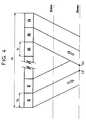
Une telle trame dite "longue" est représentée sur la figure 4.Dans une durée de trame apparaissent toutes les émissions puis lesréceptions correspondantes, la condition de non collision s'interprètegéométriquement par la disjonction des bandes E/R jusqu'à une distanceDmax.Such a so-called "long" frame is shown in FIG. 4.In a frame duration all the programs appear then thecorresponding receptions, the non-collision condition is interpretedgeometrically by the disjunction of the E / R bands up to a distanceDmax.
Dans l'exemple de réalisation représenté à la figure 5 :
- la première contrainte donne, en supposant Te = Tr Te ≦ 4,63 ms, cequi permet de prendre :
- la seconde contrainte donne :
- à 10° d'élévation F > 23,07 ms ou F > 5,01 trames GSM, d'oùm = 3 et F = 27,69 ms
- à 20° d'élévation F > 18,39 ms ou F > 3,98 trames GSM d'où m = 2et F = 18,46 ms.
- the first constraint gives, assuming Te = Tr Te ≦ 4.63 ms, which allows to take:
- the second constraint gives:
- at 10 ° elevation F> 23.07 ms or F> 5.01 GSM frames, hence m = 3 and F = 27.69 ms
- at 20 ° elevation F> 18.39 ms or F> 3.98 GSM frames hence m = 2 and F = 18.46 ms.
Dans une réalisation avantageuse basée sur le système représentésur la figure 5 on a choisi une méthode de synchronisation avec une trame courte, F = 18,46 ms puisqu'une fois la constellation en placedans la plupart des régions du globe, l'élévation dépasse 20°. Durantla phase de démarrage, une durée de trame double peut être choisie defaçon à pouvoir fonctionner à élévation nulle. Comme les deux tramespeuvent fonctionner simultanément, dans les régions à faible latitude,qui sont également des régions à faible trafic, la durée de trame peutêtre de 36,92 ms. On distingue alors les terminaux pairs et lesterminaux impairs, chacun fonctionnant avec une trame simple d'écart.Ce système à double trame permet de maximiser la capacité dessatellites.In an advantageous embodiment based on the system shownin Figure 5 we chose a synchronization method with ashort frame, F = 18.46 ms since once the constellation is in placein most regions of the globe, the elevation exceeds 20 °. Duringthe start-up phase, a double frame duration can be chosen fromso that it can operate at zero elevation. Like the two framescan operate simultaneously in low latitude regions,which are also low traffic areas, the frame time canbe 36.92 ms. A distinction is then made between even terminals andodd terminals, each operating with a single gap frame.This double weft system maximizes the capacity ofsatellites.
Le seul problème qui peut se poser est l'émission d'un terminald'une parité, à faible élévation, durant la réception d'un terminal deparité opposée situé dans le voisinage de ce dernier; Mais il y a deuxremèdes à cette situation dont un calcul de probabilité indique lafaible fréquence. Le premier relève de l'attribution des ressourcespar la même station. En effet, les deux terminaux dépendent enprincipe de la même-station de connexion, puisqu'ils sont proches l'unde l'autre. L'algorithme d'attribution de ressources peut faire ensorte que les terminaux pairs et impairs n'aient pas accès aux mêmescanaux, ce qui en principe résoud le problème pour la grande majoritédes situations opérationnelles. Le second est d'effectuer un"hand-over" dès détection d'un brouillage persistant.The only problem that can arise is the transmission of a terminala parity, at low elevation, during the reception of a terminalopposite parity located in the vicinity of the latter; But there are tworemedies for this situation of which a probability calculation indicates thelow frequency. The first relates to the allocation of resourcesby the same station. Indeed, the two terminals depend onprinciple of the same connection station, since they are close onethe other. The resource allocation algorithm can doso that even and odd terminals do not have access to the samechannels, which in principle solves the problem for the vast majorityoperational situations. The second is to perform a"hand-over" upon detection of persistent interference.
La structure de trame choisie, vue du satellite, comporte doncdeux intervalles émission-réception, la durée d'émission étant égale àcelle de réception. La durée d'un intervalle émission est égale àcelle d'une trame GSM, soit 4,615 ms. La durée de la trame de base estde quatre trames GSM, mais un mode de fonctionnement avec une duréedouble est possible, pour tenir compte d'un mode de fonctionnement àélévation inférieure à 20°.The chosen frame structure, seen from the satellite, therefore comprisestwo transmission-reception intervals, the transmission duration being equal tothat of reception. The duration of a transmission interval is equal tothat of a GSM frame, i.e. 4.615 ms. The duration of the basic frame isof four GSM frames, but an operating mode with a durationdouble is possible, to take into account an operating mode atelevation less than 20 °.
La structure de la trame GSM s'impose donc, puisque contraintepar l'altitude des satellites. Il faut cependant noter quel'organisation (disposition temporelle) des trames ne peut pas êtreconservée telle qu'elle, du moins dans ce mode de fonctionnement àl'alternat. Cependant fonctionnellement il est possible de disposerdes mêmes types de canaux, même si la numérotation est modifiée.The structure of the GSM frame is therefore essential, since constraintby the altitude of the satellites. However, it should be noted thatthe organization (temporal arrangement) of the frames cannot bekept as it is, at least in this operating mode atthe work-study program. However functionally it is possible to haveof the same types of channels, even if the numbering is changed.
Le débit de trame est conservé, de même que la modulation et ladurée des paquets. Les canaux de signalisation sont maintenus àl'identique. Donc à un retard additionnel, de quelques millisecondes,près les mêmes procédures peuvent être applicables.The frame rate is retained, as is the modulation andduration of packages. Signaling channels are kept atthe identical. So at an additional delay, of a few milliseconds,the same procedures may apply.
Il est bien entendu que la présente invention n'a été décrite etreprésentée qu'à titre d'exemple préférentiel et que l'on pourraremplacer ses éléments constitutifs par des éléments équivalents sans,pour autant, sortir du cadre de l'invention.It is understood that the present invention has not been described andshown only as a preferred example and that we canreplace its constituent elements with equivalent elements without,however, depart from the scope of the invention.
Claims (15)
- A communications system between low-orbit satellites and terminals, inwhich the beams (12) that provide the coverage area (14) of each satellite areturned on in accordance with a beam-hopping spatial scanning technique, thesystem being characterized in that for each of its satellites, all the terminalssituated in a same antenna beam generated by said satellite are incommunication with said satellite in a single frequency band both for theuplinks and for the downlinks, in that the transmission time interval and thereception time interval of each terminal are synchronized relative to eachother and are separated in time, in that the corresponding transmission andreception time intervals for said satellite are synchronized relative to eachother and separated in time, and in that for all of the terminals of a sameantenna beam, a time-division duplex ("TDD") is utilized for the terminal-satellitelinks.
- A communications system according to claim 1, characterized in that thecommunications antenna system of each satellite ensures uniform fluxcoverage through a plurality of beams (12).
- A communications system according to claim 2, characterized in that saidbeams are elliptical beams elongated in the direction of passage of thecorresponding satellite (15).
- A communications system according to any one of claims 1 to 3,characterized in that the access mode of said satellites is a TDMA mode.
- A communications system according to any one of claims 1 to 3,characterized in that the access mode of said satellites is a CDMA mode.
- A communications system according to claim 1, characterized in that saidsatellites are placed on polar orbits.
- A communications system according to claim 1, characterized in that saidsatellites are placed on inclined orbits.
- A communications system according to claim 7, characterized in that itemploys two Walker type satellite constellations.
- Assignment of resources forming part of a communications systembetween low-orbit satellites and terminals, in which the beams (12) thatprovide the ground coverage area (14) of each satellite are turned on inaccordance with a beam-hopping spatial scanning technique, the coveragearea being formed by a set of spots which are the swaths on the ground ofdifferent coverage area beams of each satellite, the assignment of resourcesbeing characterized in that for each satellite of the system a single frequencyband is used both for the uplinks and for the downlinks in a same antennabeam, in that the transmission and reception time intervals for said satelliteare synchronized relative to each other and separated in time, and in that forall the satellite-terminal links of a same antenna beam, a time-division duplexis utilized, said assignment of resources comprising means for illuminating insuccession groups of spots selected among the N spots of said satellite, in asequence according to the beam-hopping law; means for transmitting andreceiving in a single frequency band; and means for synchronizing thetransmissions and receptions in a time-division duplex for the satellite-terminallinks.
- Assignment of resources according to claim 9, characterized in that itcomprises frequency allocation means thereby avoiding interference betweenbeams.
- Assignment of resources according to claim 9, characterized in that itcomprises means for using all of the available band in a beam and means forbeam-hopping with space diversity.
- Assignment of resources according to claim 9, characterized in that itincludes means suitable for providing beams that are elongated in thedirection of passage of the satellite.
- A terminal forming part of a communications system between low-orbitsatellites and terminals, in which the beams (12) that provide the coveragearea (14) of each satellite are turned on in accordance with a beam-hoppingspatial scanning technique, the system being characterized in that all theterminals situated in a same antenna beam generated by said satellite are incommunication with said satellite in a single frequency band both for the uplinks and for the downlinks, in that the transmission time interval and thereception-time interval of each terminal are synchronized relative to eachother and are separated in time, and that for all the terminals of a sameantenna beam, a time-division duplex ("TDD") is utilized for the terminal-satellitelinks, said terminal comprising means for effecting synchronizationfirstly in open loop and then in closed loop with the aid of a station whichcontrols the network, and for synchronizing the transmissions and receptionsin a time-division duplex for the satellite-terminal links.
- A terminal according to claim 13, characterized in that it includestransmission means ensuring that a "first message" is sent, before the start oftransmission, whose reception by the corresponding satellite allows the timedelay which is appropriate in order to ensure perfect synchronization betweensaid terminal and said satellite to be defined.
- An interconnection earth station forming part of a communicationssystem between low-orbit satellites and terminals, in which the beams (12)that provide the coverage area (14) of each satellite are turned on inaccordance with a beam-hopping spatial scanning technique, the systembeing characterized in that for each of its satellites, all the terminals situatedin a same antenna beam generated by said satellite are in communicationwith said satellite in a single frequency band both for the uplinks and for thedownlinks, in that the transmission time interval and the reception timeinterval of each terminal are synchronized relative to each other and areseparated in time, in that the corresponding transmission and reception timeintervals for said satellite are synchronized relative to each other andseparated in time, and in that for all of the terminals of a same antenna beam,a time-division duplex ("TDD") is utilized for the terminal-satellite links, saidinterconnection station comprising means for measuring, tracking andcontrolling the synchronization of radiations and transmissions of terminalsand satellites of said system in a time-division duplex for the satellite-terminallinks.
Applications Claiming Priority (2)
| Application Number | Priority Date | Filing Date | Title |
|---|---|---|---|
| FR9112119AFR2682238B1 (en) | 1991-10-02 | 1991-10-02 | LOW ORBIT SATELLITE COMMUNICATION SYSTEM FOR TERMINALS. |
| FR9112119 | 1991-10-02 |
Publications (2)
| Publication Number | Publication Date |
|---|---|
| EP0536068A1 EP0536068A1 (en) | 1993-04-07 |
| EP0536068B1true EP0536068B1 (en) | 1999-12-08 |
Family
ID=9417508
Family Applications (1)
| Application Number | Title | Priority Date | Filing Date |
|---|---|---|---|
| EP19920420345Expired - LifetimeEP0536068B1 (en) | 1991-10-02 | 1992-10-01 | Low orbit satellite communication system with terminals as destination |
Country Status (7)
| Country | Link |
|---|---|
| EP (1) | EP0536068B1 (en) |
| JP (1) | JPH06503458A (en) |
| AU (2) | AU672758B2 (en) |
| CA (1) | CA2097504C (en) |
| DE (1) | DE69230393T2 (en) |
| FR (1) | FR2682238B1 (en) |
| WO (1) | WO1993007683A1 (en) |
Cited By (1)
| Publication number | Priority date | Publication date | Assignee | Title |
|---|---|---|---|---|
| US6314269B1 (en) | 1994-07-22 | 2001-11-06 | International Mobile Satelitte Organization | Multi-beam TDMA satellite mobile communications system |
Families Citing this family (18)
| Publication number | Priority date | Publication date | Assignee | Title |
|---|---|---|---|---|
| FR2677197B1 (en)* | 1991-05-31 | 1994-09-16 | Alcatel Espace | LOW ORBIT SATELLITE COMMUNICATION SYSTEM FOR MOBILE TERMINALS. |
| US5621415A (en)* | 1994-11-15 | 1997-04-15 | Teledesic Corporation | Linear cell satellite system |
| FI972475L (en)* | 1994-12-12 | 1997-08-12 | Ericsson Ge Mobile Inc | Diversity-oriented channel allocation in a mobile communication system |
| FR2729025B1 (en)* | 1995-01-02 | 1997-03-21 | Europ Agence Spatiale | METHOD AND SYSTEM FOR TRANSMITTING RADIO SIGNALS VIA A SATELLITE NETWORK BETWEEN A FIXED EARTH STATION AND MOBILE USER TERMINALS |
| FR2735304B1 (en)* | 1995-06-12 | 1997-07-11 | Alcatel Espace | SCROLLING SATELLITE COMMUNICATION SYSTEM, SATELLITE, STATION AND TERMINAL INCLUDED |
| US6108364A (en)* | 1995-08-31 | 2000-08-22 | Qualcomm Incorporated | Time division duplex repeater for use in a CDMA system |
| AU6987896A (en)* | 1996-09-06 | 1998-03-26 | Brigitta Wagner | Wireless communications system using beam direction multiplexing |
| FR2741493B1 (en)* | 1996-12-03 | 1998-08-21 | Europ Agence Spatiale | METHOD AND SYSTEM FOR TRANSMITTING RADIO SIGNALS VIA A SATELLITE NETWORK BETWEEN A FIXED EARTH STATION AND MOBILE USER TERMINALS |
| US5790070A (en)* | 1997-05-05 | 1998-08-04 | Motorola, Inc. | Network and method for controlling steerable beams |
| US6243366B1 (en)* | 1997-06-20 | 2001-06-05 | At&T Corp. | Method and apparatus for providing interactive two-way communications using a single one-way channel in satellite systems |
| EP1030467A1 (en)* | 1999-02-18 | 2000-08-23 | ICO Services Ltd. | Satellite communication system with beam forming elements and frequency hopping data transmitted to the user |
| US7426386B1 (en)* | 2000-06-21 | 2008-09-16 | Northrop Grumman Corporation | Beam laydown for hopped satellite downlink with adaptable duty cycle |
| US6859652B2 (en) | 2000-08-02 | 2005-02-22 | Mobile Satellite Ventures, Lp | Integrated or autonomous system and method of satellite-terrestrial frequency reuse using signal attenuation and/or blockage, dynamic assignment of frequencies and/or hysteresis |
| EP1316233B1 (en) | 2000-08-02 | 2011-10-05 | ATC Technologies, LLC | Coordinated frequency reuse of a terrestrial and a satellite system. |
| US7792488B2 (en) | 2000-12-04 | 2010-09-07 | Atc Technologies, Llc | Systems and methods for transmitting electromagnetic energy over a wireless channel having sufficiently weak measured signal strength |
| IL161882A0 (en)* | 2001-11-20 | 2005-11-20 | Qualcomm Inc | Reverse link power controlled repeater qualcomm incorporated |
| CN102540127B (en)* | 2012-01-05 | 2014-06-18 | 北京东方计量测试研究所 | Calibration platform for space potential detector of low-orbit spacecraft |
| US20210036768A1 (en)* | 2018-02-13 | 2021-02-04 | Satixfy Israel Ltd. | A Method for Implementing Beam Hopping in a Satellite Communications Network |
Family Cites Families (7)
| Publication number | Priority date | Publication date | Assignee | Title |
|---|---|---|---|---|
| FR2129898B1 (en)* | 1971-03-19 | 1975-02-21 | Thomson Csf | |
| US4292683A (en)* | 1979-11-06 | 1981-09-29 | Satellite Business Systems | Guard band reduction in open loop TDMA communications |
| US4823341A (en)* | 1986-08-14 | 1989-04-18 | Hughes Aircraft Company | Satellite communications system having frequency addressable high gain downlink beams |
| DE3644176A1 (en)* | 1986-12-23 | 1988-07-14 | Messerschmitt Boelkow Blohm | METHOD FOR TRANSMITTING DATA BY MEANS OF A GEOSTATIONAL SATELLITE AND AT LEAST A SUBSATELLITE |
| IL91529A0 (en)* | 1988-10-28 | 1990-04-29 | Motorola Inc | Satellite cellular telephone and data communication system |
| US5161248A (en)* | 1989-10-02 | 1992-11-03 | Motorola, Inc. | Method of predicting cell-to-cell hand-offs for a satellite cellular communications system |
| FR2677197B1 (en)* | 1991-05-31 | 1994-09-16 | Alcatel Espace | LOW ORBIT SATELLITE COMMUNICATION SYSTEM FOR MOBILE TERMINALS. |
- 1991
- 1991-10-02FRFR9112119Apatent/FR2682238B1/ennot_activeExpired - Fee Related
- 1992
- 1992-09-29AUAU26029/92Apatent/AU672758B2/ennot_activeCeased
- 1992-10-01EPEP19920420345patent/EP0536068B1/ennot_activeExpired - Lifetime
- 1992-10-01DEDE1992630393patent/DE69230393T2/ennot_activeExpired - Fee Related
- 1992-10-01WOPCT/FR1992/000911patent/WO1993007683A1/enactiveApplication Filing
- 1992-10-01CACA 2097504patent/CA2097504C/ennot_activeExpired - Fee Related
- 1992-10-01JPJP5506658Apatent/JPH06503458A/enactivePending
- 1996
- 1996-07-22AUAU60662/96Apatent/AU6066296A/ennot_activeAbandoned
Cited By (1)
| Publication number | Priority date | Publication date | Assignee | Title |
|---|---|---|---|---|
| US6314269B1 (en) | 1994-07-22 | 2001-11-06 | International Mobile Satelitte Organization | Multi-beam TDMA satellite mobile communications system |
Also Published As
| Publication number | Publication date |
|---|---|
| CA2097504C (en) | 1998-05-12 |
| FR2682238A1 (en) | 1993-04-09 |
| WO1993007683A1 (en) | 1993-04-15 |
| DE69230393T2 (en) | 2000-07-06 |
| AU6066296A (en) | 1996-10-03 |
| CA2097504A1 (en) | 1993-04-03 |
| FR2682238B1 (en) | 1994-10-07 |
| EP0536068A1 (en) | 1993-04-07 |
| AU2602992A (en) | 1993-04-08 |
| AU672758B2 (en) | 1996-10-17 |
| JPH06503458A (en) | 1994-04-14 |
| DE69230393D1 (en) | 2000-01-13 |
Similar Documents
| Publication | Publication Date | Title |
|---|---|---|
| EP0536068B1 (en) | Low orbit satellite communication system with terminals as destination | |
| EP3607673B1 (en) | Method and system for transporting signals in a satellite system | |
| EP0536033B1 (en) | Method of traffic switching in a low orbit satellite communication system with terminals as destination and communication system using this method | |
| CA2182444C (en) | System for transmitting radio signals via a geostationary communications satellite, particularly for communications with portable mobile terminals | |
| FR2901934A1 (en) | SATELLITE COMMUNICATION SYSTEM EMPLOYING A COMBINATION OF TIME SLICES AND ORTHOGONAL CODES | |
| EP0720308A1 (en) | Method and system for transmission of radioelectric signals via a satellite network between a fixed earth station and mobile terminals | |
| FR2766996A1 (en) | METHOD AND DEVICE FOR REDUCING SIGNAL BLOCKING IN A SATELLITE TELECOMMUNICATIONS SYSTEM | |
| FR2901933A1 (en) | SATELLITE COMMUNICATION SYSTEM FOR COMMUNICATING PACKET DATA MESSAGES | |
| FR2720887A1 (en) | Communication transfer method for satellite cellular transmission | |
| FR2740927A1 (en) | SYSTEM AND METHODS FOR INTEGRATED BANDWIDTH SHARING FROM A SATELLITE ACCESS BINDING | |
| FR2767000A1 (en) | METHOD AND APPARATUS USING MULTIPLE SPREAD CODES FOR THE TRANSMISSION OF DATA IN A TELECOMMUNICATIONS SYSTEM BY SATELLITES | |
| EP0095959A1 (en) | Frequency hopping radiocommunication system | |
| EP0516039B1 (en) | Communication system by means of satellites in low orbit to mobile stations | |
| FR2734971A1 (en) | METHOD FOR REQUESTING VOLUNTEERS FOR TRANSFER IN A CELLULAR TELECOMMUNICATIONS SYSTEM | |
| CA2784436A1 (en) | Hybrid space system based on a constellation of low-orbit satellites working as space repeaters for improving the transmission and reception of geostationary signals | |
| EP2005770A1 (en) | Method for optimizing allocation of resources in a cellular network using a shared radio transmission link, network and network adaptors thereof | |
| WO1999053644A1 (en) | Cellular radio signal with additional channel assigned to downlink, corresponding method, system and base station | |
| EP2721747A1 (en) | Device and method for optimizing the ground coverage of a hybrid space system | |
| FR2735306A1 (en) | Wireless telecommunication network system e.g. for cellular telephone | |
| WO2006013294A1 (en) | Communication network with radio signal relaying through terminal relays | |
| FR2901935A1 (en) | SYSTEM AND METHOD FOR PROVIDING AN IMPROVED TERRESTRIAL SUBSYSTEM FOR USE IN MOBILE SATELLITE SYSTEMS | |
| FR2756696A1 (en) | SATELLITE TELECOMMUNICATIONS SYSTEM AND METHOD OF IMPLEMENTATION | |
| EP1201046B1 (en) | Telecommunication method and system via moving satellites wherein communications are transferable from one satellite to another | |
| EP0887950A1 (en) | Base station with antennas diversity for the transmission of unidirectional channels and corresponding method | |
| FR2787261A1 (en) | MULTI-BEAM TELECOMMUNICATION AND SATELLITE SYSTEM FOR USE IN SUCH A SATELLITE |
Legal Events
| Date | Code | Title | Description |
|---|---|---|---|
| PUAI | Public reference made under article 153(3) epc to a published international application that has entered the european phase | Free format text:ORIGINAL CODE: 0009012 | |
| AK | Designated contracting states | Kind code of ref document:A1 Designated state(s):DE FR GB IT SE | |
| 17P | Request for examination filed | Effective date:19930809 | |
| 17Q | First examination report despatched | Effective date:19950726 | |
| GRAG | Despatch of communication of intention to grant | Free format text:ORIGINAL CODE: EPIDOS AGRA | |
| RAP1 | Party data changed (applicant data changed or rights of an application transferred) | Owner name:ALCATEL SPACE INDUSTRIES | |
| GRAG | Despatch of communication of intention to grant | Free format text:ORIGINAL CODE: EPIDOS AGRA | |
| GRAH | Despatch of communication of intention to grant a patent | Free format text:ORIGINAL CODE: EPIDOS IGRA | |
| GRAH | Despatch of communication of intention to grant a patent | Free format text:ORIGINAL CODE: EPIDOS IGRA | |
| RAP1 | Party data changed (applicant data changed or rights of an application transferred) | Owner name:ALCATEL | |
| GRAA | (expected) grant | Free format text:ORIGINAL CODE: 0009210 | |
| AK | Designated contracting states | Kind code of ref document:B1 Designated state(s):DE FR GB IT SE | |
| REF | Corresponds to: | Ref document number:69230393 Country of ref document:DE Date of ref document:20000113 | |
| GBT | Gb: translation of ep patent filed (gb section 77(6)(a)/1977) | Effective date:20000113 | |
| ITF | It: translation for a ep patent filed | ||
| PGFP | Annual fee paid to national office [announced via postgrant information from national office to epo] | Ref country code:GB Payment date:20000915 Year of fee payment:9 | |
| PGFP | Annual fee paid to national office [announced via postgrant information from national office to epo] | Ref country code:SE Payment date:20001002 Year of fee payment:9 | |
| PGFP | Annual fee paid to national office [announced via postgrant information from national office to epo] | Ref country code:DE Payment date:20001005 Year of fee payment:9 | |
| PLBE | No opposition filed within time limit | Free format text:ORIGINAL CODE: 0009261 | |
| PGFP | Annual fee paid to national office [announced via postgrant information from national office to epo] | Ref country code:FR Payment date:20001012 Year of fee payment:9 | |
| 26N | No opposition filed | ||
| PG25 | Lapsed in a contracting state [announced via postgrant information from national office to epo] | Ref country code:GB Free format text:LAPSE BECAUSE OF NON-PAYMENT OF DUE FEES Effective date:20011001 | |
| PG25 | Lapsed in a contracting state [announced via postgrant information from national office to epo] | Ref country code:SE Free format text:LAPSE BECAUSE OF NON-PAYMENT OF DUE FEES Effective date:20011002 | |
| REG | Reference to a national code | Ref country code:GB Ref legal event code:IF02 | |
| GBPC | Gb: european patent ceased through non-payment of renewal fee | Effective date:20011001 | |
| EUG | Se: european patent has lapsed | Ref document number:92420345.8 | |
| PG25 | Lapsed in a contracting state [announced via postgrant information from national office to epo] | Ref country code:DE Free format text:LAPSE BECAUSE OF NON-PAYMENT OF DUE FEES Effective date:20020702 | |
| PG25 | Lapsed in a contracting state [announced via postgrant information from national office to epo] | Ref country code:FR Free format text:LAPSE BECAUSE OF NON-PAYMENT OF DUE FEES Effective date:20030630 | |
| REG | Reference to a national code | Ref country code:FR Ref legal event code:ST | |
| PG25 | Lapsed in a contracting state [announced via postgrant information from national office to epo] | Ref country code:IT Free format text:LAPSE BECAUSE OF NON-PAYMENT OF DUE FEES;WARNING: LAPSES OF ITALIAN PATENTS WITH EFFECTIVE DATE BEFORE 2007 MAY HAVE OCCURRED AT ANY TIME BEFORE 2007. THE CORRECT EFFECTIVE DATE MAY BE DIFFERENT FROM THE ONE RECORDED. Effective date:20051001 | |
| PG25 | Lapsed in a contracting state [announced via postgrant information from national office to epo] | Ref country code:FR Free format text:LAPSE BECAUSE OF NON-PAYMENT OF DUE FEES Effective date:20011031 |