EP0534793B1 - Emergency lighting apparatus - Google Patents
Emergency lighting apparatusDownload PDFInfo
- Publication number
- EP0534793B1 EP0534793B1EP19920308785EP92308785AEP0534793B1EP 0534793 B1EP0534793 B1EP 0534793B1EP 19920308785EP19920308785EP 19920308785EP 92308785 AEP92308785 AEP 92308785AEP 0534793 B1EP0534793 B1EP 0534793B1
- Authority
- EP
- European Patent Office
- Prior art keywords
- battery
- lighting apparatus
- lamp
- power
- temperature
- Prior art date
- Legal status (The legal status is an assumption and is not a legal conclusion. Google has not performed a legal analysis and makes no representation as to the accuracy of the status listed.)
- Expired - Lifetime
Links
Images
Classifications
- H—ELECTRICITY
- H02—GENERATION; CONVERSION OR DISTRIBUTION OF ELECTRIC POWER
- H02J—CIRCUIT ARRANGEMENTS OR SYSTEMS FOR SUPPLYING OR DISTRIBUTING ELECTRIC POWER; SYSTEMS FOR STORING ELECTRIC ENERGY
- H02J9/00—Circuit arrangements for emergency or stand-by power supply, e.g. for emergency lighting
- H02J9/04—Circuit arrangements for emergency or stand-by power supply, e.g. for emergency lighting in which the distribution system is disconnected from the normal source and connected to a standby source
- H02J9/06—Circuit arrangements for emergency or stand-by power supply, e.g. for emergency lighting in which the distribution system is disconnected from the normal source and connected to a standby source with automatic change-over, e.g. UPS systems
- H02J9/062—Circuit arrangements for emergency or stand-by power supply, e.g. for emergency lighting in which the distribution system is disconnected from the normal source and connected to a standby source with automatic change-over, e.g. UPS systems for AC powered loads
- H02J9/065—Circuit arrangements for emergency or stand-by power supply, e.g. for emergency lighting in which the distribution system is disconnected from the normal source and connected to a standby source with automatic change-over, e.g. UPS systems for AC powered loads for lighting purposes
- H—ELECTRICITY
- H05—ELECTRIC TECHNIQUES NOT OTHERWISE PROVIDED FOR
- H05B—ELECTRIC HEATING; ELECTRIC LIGHT SOURCES NOT OTHERWISE PROVIDED FOR; CIRCUIT ARRANGEMENTS FOR ELECTRIC LIGHT SOURCES, IN GENERAL
- H05B41/00—Circuit arrangements or apparatus for igniting or operating discharge lamps
- H05B41/14—Circuit arrangements
- H05B41/26—Circuit arrangements in which the lamp is fed by power derived from DC by means of a converter, e.g. by high-voltage DC
- H05B41/28—Circuit arrangements in which the lamp is fed by power derived from DC by means of a converter, e.g. by high-voltage DC using static converters
- H05B41/282—Circuit arrangements in which the lamp is fed by power derived from DC by means of a converter, e.g. by high-voltage DC using static converters with semiconductor devices
- H05B41/285—Arrangements for protecting lamps or circuits against abnormal operating conditions
- H05B41/2851—Arrangements for protecting lamps or circuits against abnormal operating conditions for protecting the circuit against abnormal operating conditions
- H05B41/2856—Arrangements for protecting lamps or circuits against abnormal operating conditions for protecting the circuit against abnormal operating conditions against internal abnormal circuit conditions
Definitions
- This inventionrelates to emergency lighting apparatus.
- itrelates to lighting apparatus of the gas discharge or fluorescent tube type which is normally operated by a mains supply but which must also continue in operation when the mains supply is temporarily disconnected.
- Typical usesare emergency exit signs and other emergency luminaires.
- emergency poweris generally provided by back up batteries.
- the batteriesare generally charged by a battery charger whilst the mains supply is connected and then used to provide power for the lamp during disconnection of the mains supply.
- ballastsie inductors or inductor circuits
- emergency invertersie inductors or inductor circuits
- conventional ballastsare large inductors which can generate considerable amounts of excess heat. This heat can easily damage the batteries after a very short period of operation.
- the battery and/or the emergency gearmay be mounted remotely from the fluorescent tube; the luminaire housing can be carefully designed to minimise heat generated within it; or the housing can be adapted such that the heat sources, such as the ballast, and the battery are separated by a heat shield.
- Heatis generated not only by the ballast but also by the lamp itself, by the battery charger and/or by self-heating of the batteries on overcharge, since, when the battery is fully charged and the charging current remains connected to the battery, the current will be converted to heat rather than stored energy.
- US-A-4,866,350discloses a mains-only fluorescent lamp system in which an IC chip is used for control logic and power switching. The system does not envisage emergency use including a battery or consider the problems of charging emergency batteries.
- US-A-4,727,291relates to lighting systems having an emergency battery. Battery charging is achieved directly from a mains supply.
- US-A-4,751,398discloses a lighting system having an emergency battery, the battery being charged by a charger direct from a mains AC supply. Feedback means are employed to keep lamp output constant, despite variations in voltage and other factors.
- the present inventionarose in an attempt to design an improved emergency lighting apparatus and to widen the range of non-emergency fluorescent luminaires that may be converted to provide an emergency lighting facility.
- lighting apparatuscomprising a gas discharge lamp, an input for a mains supply, a ballast connected between the mains input and the lamp, and operating at a frequency greater than 20 kHz, a battery, a battery charger for charging the battery from the mains supply, and means for selectively using the battery or the mains supply to power the gas discharge lamp, characterised in that the battery charger operates at a frequency greater than 20 kHz.
- the apparatuscomprises a single module.
- the apparatuspreferably includes means, including a feedback means, for limiting the heat generated within the apparatus.
- High Frequency Electronic Ballastsmay be used to replace the simple inductor ballast used to control the power drawn by the fluorescent lamp. These dissipate much less power than the standard inductor ballast. They essentially work by acting as a frequency converter, converting the frequency of the standard 50 Hz mains supply (in the UK) to a few tens of thousands of hertz. At the higher frequency a much smaller inductance with far lower resistive and core losses is used to control the lamp power.
- Heat risemay alternatively or additionally be limited by using temperature sensing and feedback apparatus, in which the temperature of the lamp or battery or both is sensed and when an overheat condition occurs the power input to the lamp is reduced, within predetermined threshold limits.
- Such feedback and sensing apparatus(such as thermistors, thermocouples or semiconductor devices) is well known per se, and many examples thereof will be clear to the skilled man in the art.
- a simple bimetallic stripmay be used.
- battery voltagemay be used to measure battery temperature . Battery voltage can be used as a temperature indicator if the battery characteristic is well understood with respect to state of charge, age, internal resistance, and whether the battery is being charged or discharged. Thus, battery temperature sensing can be carried out without an additional sensor. Temperature controlled components may also be used.
- Temperature sensing componentsmay be used to monitor one or more temperature sensitive areas within the luminaire, such as batteries, lamp and air temperature and their output used to control the waveform generated by the frequency converter, so that the power used by the lamp and hence the heat generated by it may be controlled. This may be used to ensure that the temperature of battery, tube or other component does not exceed its optimal or maximum operating temperature. The amount of variation in controlled tube power may be limited so that there is no apparent loss in illumination. This is aided by the fluorescent lamp characteristic of light output decreasing if the optimal temperature is exceeded, in this case decreasing the lamp power would increase, or at least maintain, light output. A further input may be provided to enable external control of light output and give a full range dimming facility.
- the limitation of the temperature riseallows all of the apparatus to be housed within a luminaire which may be a conventional luminaire housing, or alternatively may be a specially designed housing.
- a heat generation reduction techniqueis to replace the usual 240 volt 50 Hz transformer, used to provide a low voltage battery charging supply (in the UK), with a high frequency transformer with lower core and winding losses.
- the frequency converterthat usually only drives the lamp, is used to drive this transformer.
- the outputmay drive any form of charger circuit such as a taper charger (simple resistor), semiconductor controlled constant current, semiconductor controlled constant voltage, and dual rate chargers.
- the battery chargermay be controlled such that when the battery has been fully charged the charge current is reduced, thus reducing the temperature rise caused by overcharge.
- the means for sensing battery overchargemay include, for example, means for sensing the temperature rise of the battery, means for sensing the flat voltage of the battery changing, timer means adapted to reduce the charge current after a predetermined period from the start of the recharge period, or any combination of these.
- a dual rate chargerby either sensing the fully charged state or after charging for a set time period, sufficient to fully charge a completely discharged battery, reduces the charge current to a trickle rate and hence minimise the temperature rise.
- the electronic ballast and the battery chargermay be integrated into one unit, or formed as a single integrated circuit. This can enable the same component to do both jobs. Indeed, the entire circuit (other than components such as the battery and the lamp) may be configured into a single unit, by applying standard methods of reducing circuit components into semiconductor integrated circuit configurations.
- Electronic ballasts or inductor circuitsare available and can offer reduced running temperatures and improve performance of the lamps on starting and normal running.
- the feedback meansmay be adapted to keep the lamp running temperature as close, within a predetermined range, to the optimum efficiency as possible.
- the operation of the frequency converteris not reliant upon any load it drives (apart from an overload fault condition, where power from frequency converter may be limited electronically, or the converter turned off completely or in the case of a gross overload a fuse will rupture interrupting the supply to the apparatus).
- Thisenables the apparatus to drive any number of lamps, including none, limited only by the power of the frequency converter.
- any number of lampsmay be removed or fail to strike without affecting the operation of those remaining or the battery charging facility.
- Lamps powered by the apparatusmay be individually or collectively switched on and off by connection and disconnection to the frequency converter via, for example, a relay or solid state device controlled by a standard wall switch or other control device. This arrangement does not significantly interfere with the charging facility.
- the frequency converter circuitmay include a facility to monitor the mains supply voltage so that it will cease operation if the voltage falls below a limit (eg as specified in a relevant emergency lighting standard), and resume operation when the voltage raises to a limit (specified in the same standard).
- the emergency lighting facilitywill sense the resulting cessation of battery charger output and either power a lamp (fluorescent, incandescent, etc) used only for emergency lighting, or power one or more fluorescent lamps previously powered by the frequency converter. When the charger output is resumed, the emergency lighting facility will cease powering any lamp used for emergency lighting only.
- Filteringmay also be provided to limit the imposition of high frequency noise onto the mains supply by the apparatus.
- an emergency lighting systemcomprises a lamp 1 (which will normally be a fluorescent lamp) which may be powered by either a mains supply 2 or by an emergency battery 3 and an emergency ballast 4.
- An unswitched live sourceis applied via a frequency converter 5 to a high frequency electronic ballast 6.
- the frequency converter 5provides output power at a frequency of 30 kHz. This frequency is not critical but the frequency converter 5 should provide power at a frequency greater than 20 kHz.
- the ballast 6has variable output and is controllable by a control circuit 7 having a number of inputs as described below.
- the outputs from the ballast 6 and from the emergency ballast 4are applied to a changeover network 8 which can switch between the two so that it can either receive a signal from the mains via the ballast 6 or a signal from the battery via ballast 4. In both cases, power is used to drive the lamp.
- a battery charger 9is connected between the frequency converter 5 and the battery 3 so that, when the lamp is being powered by the mains, the battery charger 9 is actuated by the mains and used to charge up the battery 3.
- the frequency converter circuit 5includes a means such as a threshold detector for monitoring the mains supply voltage. If the mains supply voltage falls below the set threshold, then the frequency converter may be adapted to cease operation and to instead generate a mains presence signal on a line 10 to the changeover network 8 to enable the changeover network 8 to receive power from battery 3. Thus, the battery charger will cease powering the battery and instead the battery will be discharged through ballast 4 and changeover network 8 to power lamp 1.
- the mains voltagecontinues to be monitored and, as soon as it rises above the threshold, the frequency converter is again brought into operation, power is taken from the mains to the lamp and the battery begins to be charged again by battery charger 9.
- the threshold levelmay be selected by the user, or more probably determined by regulation or safety standards.
- manual and/or emergency testing apparatusmay be included in the system.
- one or more monitoring elementssuch as light sensors sensing the output of the lamp or voltage or current sensors sensing output from the mains and/or battery can be connected to a communication circuit so that the operation and condition of the unit can be controlled and monitored from a remote point.
- thiscomprises a central station monitoring a plurality of different emergency lighting units around a building for example.
- the means connecting each emergency unit with the central stationmay be a communications bus. It may alternatively be the mains supply using standard mains signalling techniques, a wireless transmission system such as a radio frequency transmission system or an optical fibre. Other methods will be apparent.
- the battery charger 9is controlled so that when the battery has been fully charged or partially charged to a predetermined extent the charge current is reduced or ceased, thus reducing the temperature rise caused by over charge.
- a timing/temperature control unit 11which can act to reduce or cease the charging current if necessary.
- Control unit 11may receive signals from a battery temperature sensor 12 arranged to sense the temperature of air in the immediate vicinity of the battery or from a battery voltage or impedance sensor (not shown). It may alternatively or additionally include a timing means which reduces the charge current after a predetermined time period from the start of a recharge period.
- the battery chargermay be provided with a charge indicator 13 which, in this example, is an LED which illuminates to show that charging is being done.
- the battery chargermay be a dual rate charger.
- the temperature of the lampmay also be sensed, for example by a suitably placed temperature sensor 14.
- An output from the temperature sensor 14may be applied to the baliast control circuit to reduce the power output from the high frequency ballast and thus to reduce the lamp's temperature.
- the sensing meansmay be, for example a thermistor, thermocouple or semiconductor device or circuit.
- Other temperature parameters within or adjacent the luminairemay alternatively or in addition be sensed, such as the battery, as described above, or indeed the air temperature at any point.
- the characteristic of such a lampis that if the optimal temperature of the lamp is exceeded the light output of the lamp actually decreases. In this case, by decreasing the lamp input power and hence temperature, the light output of the lamp may actually increase, which is clearly advantageous.
- An input 15 from a dimmer switchmay also be applied to control circuit 7 to reduce the power input of the lamp and reduce the light output of the lamp where required.
- battery voltagemay alternatively be sensed. Impedance may also be used and related to temperature. Alternatively, a fuzzy logic means may be applied as part of the feedback system.
- the emergency inverter or ballast 4may in some circumstances be designed such that the power output of the lamp is controlled so that at start-up its light output is maximised and is then controlled to compensate for the fall in battery voltage as the battery is discharged during the full emergency period. This can help to maximise the conversion of useful battery power into light output.
- a switched live source 16may be used as a direct on/off input to ballast control circuit 7.
- the ballast control circuit 7, the ballast 6, the change-over network 8, the lamp 1, the emergency ballast 4, the frequency converter 5, the batter charger 9, the battery 3, the time/temperature control 11 and the temperature sensor 12,14are formed as a single unit. Also, the frequency converter 5, the ballast 6 and the battery charger 9 are formed as a single integrated circuit.
Landscapes
- Business, Economics & Management (AREA)
- Emergency Management (AREA)
- Engineering & Computer Science (AREA)
- Power Engineering (AREA)
- Circuit Arrangement For Electric Light Sources In General (AREA)
- Secondary Cells (AREA)
Description
- This invention relates to emergency lighting apparatus. In particular, it relates to lighting apparatus of the gas discharge or fluorescent tube type which is normally operated by a mains supply but which must also continue in operation when the mains supply is temporarily disconnected. Typical uses are emergency exit signs and other emergency luminaires. Where a separate generator is not available for periods of mains interruption, emergency power is generally provided by back up batteries. The batteries are generally charged by a battery charger whilst the mains supply is connected and then used to provide power for the lamp during disconnection of the mains supply.
- The devices presently available for emergency lighting use conventional ballasts (ie inductors or inductor circuits) and emergency inverters. However, conventional ballasts are large inductors which can generate considerable amounts of excess heat. This heat can easily damage the batteries after a very short period of operation. Other than accepting a very short battery life, methods of solving the problem to date have included one or more of the following: the battery and/or the emergency gear may be mounted remotely from the fluorescent tube; the luminaire housing can be carefully designed to minimise heat generated within it; or the housing can be adapted such that the heat sources, such as the ballast, and the battery are separated by a heat shield. Heat is generated not only by the ballast but also by the lamp itself, by the battery charger and/or by self-heating of the batteries on overcharge, since, when the battery is fully charged and the charging current remains connected to the battery, the current will be converted to heat rather than stored energy.
- Most of the above previous solutions have involved specially designing or modifying a luminaire housing. This can be expensive and is not practical for retro-fitting existing units.
- US-A-4,866,350 discloses a mains-only fluorescent lamp system in which an IC chip is used for control logic and power switching. The system does not envisage emergency use including a battery or consider the problems of charging emergency batteries.
- US-A-4,727,291 relates to lighting systems having an emergency battery. Battery charging is achieved directly from a mains supply.
- US-A-4,751,398 discloses a lighting system having an emergency battery, the battery being charged by a charger direct from a mains AC supply. Feedback means are employed to keep lamp output constant, despite variations in voltage and other factors.
- The present invention arose in an attempt to design an improved emergency lighting apparatus and to widen the range of non-emergency fluorescent luminaires that may be converted to provide an emergency lighting facility.
- According to the present invention there is provided lighting apparatus comprising a gas discharge lamp, an input for a mains supply, a ballast connected between the mains input and the lamp, and operating at a frequency greater than 20 kHz, a battery, a battery charger for charging the battery from the mains supply, and means for selectively using the battery or the mains supply to power the gas discharge lamp, characterised in that the battery charger operates at a frequency greater than 20 kHz.
- Preferably the apparatus comprises a single module.
- The apparatus preferably includes means, including a feedback means, for limiting the heat generated within the apparatus.
- High Frequency Electronic Ballasts may be used to replace the simple inductor ballast used to control the power drawn by the fluorescent lamp. These dissipate much less power than the standard inductor ballast. They essentially work by acting as a frequency converter, converting the frequency of the standard 50 Hz mains supply (in the UK) to a few tens of thousands of hertz. At the higher frequency a much smaller inductance with far lower resistive and core losses is used to control the lamp power.
- Heat rise may alternatively or additionally be limited by using temperature sensing and feedback apparatus, in which the temperature of the lamp or battery or both is sensed and when an overheat condition occurs the power input to the lamp is reduced, within predetermined threshold limits. Such feedback and sensing apparatus (such as thermistors, thermocouples or semiconductor devices) is well known per se, and many examples thereof will be clear to the skilled man in the art. In one embodiment, a simple bimetallic strip may be used. Alternatively, battery voltage may be used to measure battery temperature . Battery voltage can be used as a temperature indicator if the battery characteristic is well understood with respect to state of charge, age, internal resistance, and whether the battery is being charged or discharged. Thus, battery temperature sensing can be carried out without an additional sensor. Temperature controlled components may also be used.
- Temperature sensing components may be used to monitor one or more temperature sensitive areas within the luminaire, such as batteries, lamp and air temperature and their output used to control the waveform generated by the frequency converter, so that the power used by the lamp and hence the heat generated by it may be controlled. This may be used to ensure that the temperature of battery, tube or other component does not exceed its optimal or maximum operating temperature. The amount of variation in controlled tube power may be limited so that there is no apparent loss in illumination. This is aided by the fluorescent lamp characteristic of light output decreasing if the optimal temperature is exceeded, in this case decreasing the lamp power would increase, or at least maintain, light output. A further input may be provided to enable external control of light output and give a full range dimming facility.
- Battery life may therefore be extended by limitation of this temperature rise. The limitation of the temperature rise allows all of the apparatus to be housed within a luminaire which may be a conventional luminaire housing, or alternatively may be a specially designed housing.
- A heat generation reduction technique is to replace the usual 240 volt 50 Hz transformer, used to provide a low voltage battery charging supply (in the UK), with a high frequency transformer with lower core and winding losses. The frequency converter, that usually only drives the lamp, is used to drive this transformer. As with the 50 Hz transformer, the output may drive any form of charger circuit such as a taper charger (simple resistor), semiconductor controlled constant current, semiconductor controlled constant voltage, and dual rate chargers.
- In some embodiments the battery charger may be controlled such that when the battery has been fully charged the charge current is reduced, thus reducing the temperature rise caused by overcharge. The means for sensing battery overcharge may include, for example, means for sensing the temperature rise of the battery, means for sensing the flat voltage of the battery changing, timer means adapted to reduce the charge current after a predetermined period from the start of the recharge period, or any combination of these.
- When charging nickel-cadmium batteries from a constant current source for example, when the batteries become fully charged their temperature rises, possibly causing them to exceed their maximum rating. A dual rate charger, by either sensing the fully charged state or after charging for a set time period, sufficient to fully charge a completely discharged battery, reduces the charge current to a trickle rate and hence minimise the temperature rise.
- The electronic ballast and the battery charger may be integrated into one unit, or formed as a single integrated circuit. This can enable the same component to do both jobs. Indeed, the entire circuit (other than components such as the battery and the lamp) may be configured into a single unit, by applying standard methods of reducing circuit components into semiconductor integrated circuit configurations.
- Electronic ballasts or inductor circuits are available and can offer reduced running temperatures and improve performance of the lamps on starting and normal running.
- It will be appreciated that by limiting the power to the lamp unit, to limit the temperature rise, the output of the lamp will decrease. However, since the efficiency of gas discharge lamps such as fluorescent lamps reduces if their running temperature gets too high an optimum is achievable. The feedback means may be adapted to keep the lamp running temperature as close, within a predetermined range, to the optimum efficiency as possible.
- In apparatus according to the invention the operation of the frequency converter is not reliant upon any load it drives (apart from an overload fault condition, where power from frequency converter may be limited electronically, or the converter turned off completely or in the case of a gross overload a fuse will rupture interrupting the supply to the apparatus). This enables the apparatus to drive any number of lamps, including none, limited only by the power of the frequency converter. Moreover any number of lamps may be removed or fail to strike without affecting the operation of those remaining or the battery charging facility. Lamps powered by the apparatus may be individually or collectively switched on and off by connection and disconnection to the frequency converter via, for example, a relay or solid state device controlled by a standard wall switch or other control device. This arrangement does not significantly interfere with the charging facility.
- The frequency converter circuit may include a facility to monitor the mains supply voltage so that it will cease operation if the voltage falls below a limit (eg as specified in a relevant emergency lighting standard), and resume operation when the voltage raises to a limit (specified in the same standard). The emergency lighting facility will sense the resulting cessation of battery charger output and either power a lamp (fluorescent, incandescent, etc) used only for emergency lighting, or power one or more fluorescent lamps previously powered by the frequency converter. When the charger output is resumed, the emergency lighting facility will cease powering any lamp used for emergency lighting only.
- In order to comply with regulations it may in some embodiments be necessary to precede the frequency converter with an active power factor correction circuit, particularly when driving higher power or multiple fluorescent lamps.
- Filtering may also be provided to limit the imposition of high frequency noise onto the mains supply by the apparatus.
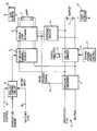
- An embodiment of the invention will now be described, by way of example only, with reference to the accompanying drawing which shows schematically an emergency lighting system.
- Referring to the Figure, an emergency lighting system comprises a lamp 1 (which will normally be a fluorescent lamp) which may be powered by either a mains supply 2 or by an emergency battery 3 and an emergency ballast 4.
- An unswitched live source is applied via a
frequency converter 5 to a high frequency electronic ballast 6. In the present example, thefrequency converter 5 provides output power at a frequency of 30 kHz. This frequency is not critical but thefrequency converter 5 should provide power at a frequency greater than 20 kHz. The ballast 6 has variable output and is controllable by acontrol circuit 7 having a number of inputs as described below. The outputs from the ballast 6 and from the emergency ballast 4 are applied to achangeover network 8 which can switch between the two so that it can either receive a signal from the mains via the ballast 6 or a signal from the battery via ballast 4. In both cases, power is used to drive the lamp. - A
battery charger 9 is connected between thefrequency converter 5 and the battery 3 so that, when the lamp is being powered by the mains, thebattery charger 9 is actuated by the mains and used to charge up the battery 3. Thefrequency converter circuit 5 includes a means such as a threshold detector for monitoring the mains supply voltage. If the mains supply voltage falls below the set threshold, then the frequency converter may be adapted to cease operation and to instead generate a mains presence signal on aline 10 to thechangeover network 8 to enable thechangeover network 8 to receive power from battery 3. Thus, the battery charger will cease powering the battery and instead the battery will be discharged through ballast 4 andchangeover network 8 to power lamp 1. The mains voltage continues to be monitored and, as soon as it rises above the threshold, the frequency converter is again brought into operation, power is taken from the mains to the lamp and the battery begins to be charged again bybattery charger 9. - The threshold level may be selected by the user, or more probably determined by regulation or safety standards.
- It will be appreciated that manual and/or emergency testing apparatus may be included in the system. In one example of this, one or more monitoring elements such as light sensors sensing the output of the lamp or voltage or current sensors sensing output from the mains and/or battery can be connected to a communication circuit so that the operation and condition of the unit can be controlled and monitored from a remote point. Typically, this comprises a central station monitoring a plurality of different emergency lighting units around a building for example. In one example the means connecting each emergency unit with the central station may be a communications bus. It may alternatively be the mains supply using standard mains signalling techniques, a wireless transmission system such as a radio frequency transmission system or an optical fibre. Other methods will be apparent.
- It is preferable that the
battery charger 9 is controlled so that when the battery has been fully charged or partially charged to a predetermined extent the charge current is reduced or ceased, thus reducing the temperature rise caused by over charge. This is achieved by a timing/temperature control unit 11 which can act to reduce or cease the charging current if necessary.Control unit 11 may receive signals from a battery temperature sensor 12 arranged to sense the temperature of air in the immediate vicinity of the battery or from a battery voltage or impedance sensor (not shown). It may alternatively or additionally include a timing means which reduces the charge current after a predetermined time period from the start of a recharge period. In general, if the type of battery being used is known, it is relatively easy for those skilled in the art to calculate the time required to fully charge a battery after any particular discharge period. The predetermined time period of thetimer 11 can be based upon this. The battery charger may be provided with acharge indicator 13 which, in this example, is an LED which illuminates to show that charging is being done. The battery charger may be a dual rate charger. - The temperature of the lamp may also be sensed, for example by a suitably placed
temperature sensor 14. An output from thetemperature sensor 14 may be applied to the baliast control circuit to reduce the power output from the high frequency ballast and thus to reduce the lamp's temperature. It will be appreciated that other types of feedback could also be used, the fundamental idea being that when an overheat condition is sensed at the lamp the power input to the lamp is reduced, within predetermined threshold limits. The sensing means may be, for example a thermistor, thermocouple or semiconductor device or circuit. Other temperature parameters within or adjacent the luminaire may alternatively or in addition be sensed, such as the battery, as described above, or indeed the air temperature at any point. It will be noted that when the lamp is a fluorescent one, the characteristic of such a lamp is that if the optimal temperature of the lamp is exceeded the light output of the lamp actually decreases. In this case, by decreasing the lamp input power and hence temperature, the light output of the lamp may actually increase, which is clearly advantageous. - An
input 15 from a dimmer switch (not shown) may also be applied to controlcircuit 7 to reduce the power input of the lamp and reduce the light output of the lamp where required. - It will be appreciated that many different methods of reducing temperature within the system may be used. The object of this is to increase battery reliability and duration of battery life whilst allowing the entire system to confined into a small space.
- As an alternative to the direct measurement of temperature, it has been described above how battery voltage may alternatively may be sensed. Impedance may also be used and related to temperature. Alternatively, a fuzzy logic means may be applied as part of the feedback system.
- The emergency inverter or ballast 4 may in some circumstances be designed such that the power output of the lamp is controlled so that at start-up its light output is maximised and is then controlled to compensate for the fall in battery voltage as the battery is discharged during the full emergency period. This can help to maximise the conversion of useful battery power into light output.
- A switched live source 16 may be used as a direct on/off input to
ballast control circuit 7. - The
ballast control circuit 7, the ballast 6, the change-overnetwork 8, the lamp 1, the emergency ballast 4, thefrequency converter 5, thebatter charger 9, the battery 3, the time/temperature control 11 and thetemperature sensor 12,14 are formed as a single unit. Also, thefrequency converter 5, the ballast 6 and thebattery charger 9 are formed as a single integrated circuit.
Claims (17)
- Lighting apparatus comprising a gas discharge lamp (1), an input for a mains supply (2), a ballast (6) connected between the mains input and the lamp, and operating at a frequency greater than 20 kHz, a battery (3), a battery charger (9) for charging the battery from the mains supply, and means (8) for selectively using the battery or the mains supply to power the gas discharge lamp, characterised in that the battery charger operates at a frequency greater than 20 kHz.
- Lighting apparatus as claimed in Claim 1, including a common frequency converter (5) for providing output power at a frequency greater than 20 kHz to both the ballast and the battery charger, said common frequency converter receiving input power from the mains supply.
- Lighting apparatus as claimed in Claim 18, in which the ballast, the battery charger and the frequency converter are formed as a single integrated circuit.
- Lighting apparatus as claimed in any one of Claims 1 to 3, including means (11,12) for controlling the output of the battery charger in accordance with a parameter related to the state of charge of the battery.
- Lighting apparatus as claimed in Claim 1 and further including means (12,14,7,11), including a feedback means, for limiting the heat generated within the apparatus.
- Lighting apparatus as claimed in Claim 5, further comprising means (14) for sensing the temperature of the lamp and feedback means (6,7) for adjusting the power input to the lamp in accordance with the temperature thereof.
- Lighting apparatus as claimed in any preceding claim, including means (12) for sensing a battery parameter, such as voltage or impedance and feedback means for adjusting the power input to the battery in dependence upon this parameter.
- Lighting apparatus as claimed in any preceding claim, including means (11) for sensing when the battery is fully charged or partially charged to a predetermined extent and for reducing or ceasing operation of the battery charger under the specified condition.
- Lighting apparatus as claimed in any preceding claim wherein the apparatus is held in a single luminaire.
- Lighting apparatus as claimed in any preceding claim, wherein the battery is connected through a means which can vary the output to the lamp, when the battery is powering the lamp, so that light output is maximised at commencement of battery operation and controlled to compensate for the fall in battery voltage as the battery discharges.
- Lighting apparatus as claimed in any one of the preceding claims, wherein the frequency converter includes means (10) for determining whether a mains signal is present or not and, if not, to configure the apparatus so that power is taken from the battery and to disconnect the battery charger.
- Lighting apparatus as claimed in any one of the preceding claims, wherein the electronic ballast is controlled by a control circuit (7) having at least one control input (14,15,16).
- Lighting apparatus as claimed in Claim 12, wherein said at least one control input to the control circuit for the ballast is one or more of an on/off input (16), a dimmer control (15), a battery temperature sensor and/or a temperature sensor (12,14) adapted to sense temperature at a point within or adjacent the luminaire.
- Lighting apparatus as claimed in Claim 13, in which battery voltage is sensed and used to indicate temperature.
- Lighting apparatus as claimed in Claim 5, wherein the feedback means includes a fuzzy logic controller.
- Lighting apparatus as claimed in any preceding claim including control and monitoring apparatus which is remote from the lamp and means for communicating with the remote control apparatus.
- Lighting apparatus as claimed in Claim 16, wherein the communicating means is a bus, optical fibre means, a wireless link or means for applying signals over a mains power system.
Applications Claiming Priority (2)
| Application Number | Priority Date | Filing Date | Title |
|---|---|---|---|
| GB9120630 | 1991-09-27 | ||
| GB919120630AGB9120630D0 (en) | 1991-09-27 | 1991-09-27 | Emergency lighting apparatus |
Publications (2)
| Publication Number | Publication Date |
|---|---|
| EP0534793A1 EP0534793A1 (en) | 1993-03-31 |
| EP0534793B1true EP0534793B1 (en) | 1996-02-28 |
Family
ID=10702116
Family Applications (1)
| Application Number | Title | Priority Date | Filing Date |
|---|---|---|---|
| EP19920308785Expired - LifetimeEP0534793B1 (en) | 1991-09-27 | 1992-09-25 | Emergency lighting apparatus |
Country Status (3)
| Country | Link |
|---|---|
| EP (1) | EP0534793B1 (en) |
| DE (1) | DE69208575T2 (en) |
| GB (1) | GB9120630D0 (en) |
Cited By (2)
| Publication number | Priority date | Publication date | Assignee | Title |
|---|---|---|---|---|
| KR100614393B1 (en) | 2004-09-24 | 2006-08-21 | 삼성에스디아이 주식회사 | Battery pack with alarm on heating |
| WO2015102896A1 (en)* | 2014-01-03 | 2015-07-09 | Capstone Lighting Technologies, LLC | Switch state detection and controlling electrical power |
Families Citing this family (14)
| Publication number | Priority date | Publication date | Assignee | Title |
|---|---|---|---|---|
| ES2148771T3 (en)* | 1995-09-20 | 2000-10-16 | Bosch Gmbh Robert | THERMALLY PROTECTED CONTROL DEVICE, CONTAINING ELECTRICAL COMPONENTS. |
| AUPN840396A0 (en)* | 1996-03-04 | 1996-03-28 | J - Lec Systems Pty Limited | Intrinsically safe emergency light and sound system |
| US5998941A (en)* | 1997-08-21 | 1999-12-07 | Parra; Jorge M. | Low-voltage high-efficiency fluorescent signage, particularly exit sign |
| ATE254386T1 (en)* | 1997-09-18 | 2003-11-15 | Ceag Sicherheitstechnik Gmbh | LIGHTING SYSTEM |
| WO1999062305A1 (en)* | 1998-05-22 | 1999-12-02 | Ideas Electronics (S) Pte Ltd. | Apparatus for supplying electrical power to a discharge lamp |
| US6392364B1 (en)* | 1999-06-21 | 2002-05-21 | Denso Corporation | High voltage discharge lamp apparatus for vehicles |
| FI111323B (en)* | 2001-07-04 | 2003-06-30 | Teknoware Oy | Safety light arrangement and safety light device |
| DE10312933A1 (en)* | 2003-03-22 | 2004-10-14 | Micro-Hybrid Electronic Gmbh | Electronic module for emergency lamps effective, when current supply for normal illumination system has failed, consisting of direct to alternating current (DC/AC) converter with downward transformation characteristic |
| DE102004007006A1 (en)* | 2004-02-12 | 2005-08-25 | Lamptronic International Gmbh & Co.Kg | Temperature-controlled electronic circuit for starting and running fluorescent lamps, uses temperature sensor in circuit reducing power at higher temperatures |
| TWM255614U (en)* | 2004-03-15 | 2005-01-11 | Jau-Dung Guo | Illumination device with emergency lighting function |
| NL2005187C2 (en)* | 2010-07-30 | 2012-01-31 | Solid Semecs B V | EMERGENCY LIGHTING SYSTEM AND CONTROL SYSTEM THEREFORE. |
| US8659232B2 (en) | 2010-09-14 | 2014-02-25 | Crs Electronics | Variable-impedance load for LED lamps |
| DE102011008572A1 (en)* | 2011-01-14 | 2012-07-19 | Ceag Notlichtsysteme Gmbh | Central supply system and method for simultaneous dimming of a plurality of luminaires |
| DE102012224210B4 (en)* | 2012-12-21 | 2022-08-11 | Tridonic Gmbh & Co Kg | Temperature-dependent charging current control for emergency lighting devices |
Family Cites Families (4)
| Publication number | Priority date | Publication date | Assignee | Title |
|---|---|---|---|---|
| US3900783A (en)* | 1974-04-08 | 1975-08-19 | Gen Electric | Battery charging circuit |
| US4727291A (en)* | 1985-10-15 | 1988-02-23 | Bavco Manufacturing Co. | Back-up electrical system for lamps |
| US4751398A (en)* | 1986-03-18 | 1988-06-14 | The Bodine Company | Lighting system for normal and emergency operation of high intensity discharge lamps |
| US4866350A (en)* | 1988-04-04 | 1989-09-12 | Usi Lighting, Inc. | Fluorescent lamp system |
- 1991
- 1991-09-27GBGB919120630Apatent/GB9120630D0/enactivePending
- 1992
- 1992-09-25DEDE1992608575patent/DE69208575T2/ennot_activeExpired - Fee Related
- 1992-09-25EPEP19920308785patent/EP0534793B1/ennot_activeExpired - Lifetime
Cited By (6)
| Publication number | Priority date | Publication date | Assignee | Title |
|---|---|---|---|---|
| KR100614393B1 (en) | 2004-09-24 | 2006-08-21 | 삼성에스디아이 주식회사 | Battery pack with alarm on heating |
| WO2015102896A1 (en)* | 2014-01-03 | 2015-07-09 | Capstone Lighting Technologies, LLC | Switch state detection and controlling electrical power |
| US9425649B2 (en) | 2014-01-03 | 2016-08-23 | Capstone Lighting Technologies, Llc. | Apparatus and method for switch state detection and controlling electrical power |
| CN105981259A (en)* | 2014-01-03 | 2016-09-28 | 顶点照明科技有限公司 | Switch state detection and controlling electrical power |
| US9608479B2 (en) | 2014-01-03 | 2017-03-28 | Capstone Lighting Technologies, Llc. | Apparatus and method for switch state detection and controlling electrical power |
| US10230262B2 (en) | 2014-01-03 | 2019-03-12 | Capstone Lighting Technologies, Llc. | Apparatus and method for switch state detection and controlling electrical power |
Also Published As
| Publication number | Publication date |
|---|---|
| EP0534793A1 (en) | 1993-03-31 |
| GB9120630D0 (en) | 1991-11-06 |
| DE69208575D1 (en) | 1996-04-04 |
| DE69208575T2 (en) | 1996-07-11 |
Similar Documents
| Publication | Publication Date | Title |
|---|---|---|
| EP0534793B1 (en) | Emergency lighting apparatus | |
| US4727291A (en) | Back-up electrical system for lamps | |
| CN104054395B (en) | lighting device | |
| US4751398A (en) | Lighting system for normal and emergency operation of high intensity discharge lamps | |
| CA2766422C (en) | Electronic circuit for converting a mains-operated luminaire into an emergency luminaire | |
| EP2798267B1 (en) | Dimming control for emergency lighting systems | |
| WO1989007855A1 (en) | Backup electrical system for lamps | |
| KR20080080352A (en) | Control device charged from light source, control device charging method, control device charging system, remote sensor, remote sensor charging method, remote sensor charging system | |
| US4686424A (en) | Emergency lighting circuits | |
| US5910689A (en) | Generator standby ballast | |
| US6753651B1 (en) | Emergency ballast with battery heater | |
| EP1274286A1 (en) | Emergency lighting apparatus | |
| CN103621180A (en) | Lighting device | |
| US7804255B2 (en) | Dimming system powered by two current sources and having an operation indicator module | |
| US6049178A (en) | Circuit for controlling operation of an emergency exit lamp | |
| EP2909916B1 (en) | Led tube for emergency lighting system | |
| US3599070A (en) | Battery charger and emergency power supply for illumination device | |
| FI66271B (en) | KRETS FOER GASURLADDNINGSLAMPOR | |
| US7161312B2 (en) | Distributed fluorescent light control system | |
| GB2101426A (en) | Emergency lighting | |
| KR200207662Y1 (en) | Ballast circuit for emergency lighting | |
| US7619367B2 (en) | Electronic ballast protection | |
| JP2000102190A (en) | Solar battery lighting equipment | |
| KR101058351B1 (en) | Battery charge / discharge control circuit with regulator and inverter | |
| KR100831739B1 (en) | Lighting control device for emergency lighting |
Legal Events
| Date | Code | Title | Description |
|---|---|---|---|
| PUAI | Public reference made under article 153(3) epc to a published international application that has entered the european phase | Free format text:ORIGINAL CODE: 0009012 | |
| AK | Designated contracting states | Kind code of ref document:A1 Designated state(s):DE FR GB IT NL | |
| 17P | Request for examination filed | Effective date:19930518 | |
| 17Q | First examination report despatched | Effective date:19941129 | |
| GRAA | (expected) grant | Free format text:ORIGINAL CODE: 0009210 | |
| AK | Designated contracting states | Kind code of ref document:B1 Designated state(s):DE FR GB IT NL | |
| ITF | It: translation for a ep patent filed | ||
| REF | Corresponds to: | Ref document number:69208575 Country of ref document:DE Date of ref document:19960404 | |
| ET | Fr: translation filed | ||
| PLBE | No opposition filed within time limit | Free format text:ORIGINAL CODE: 0009261 | |
| 26N | No opposition filed | ||
| PGFP | Annual fee paid to national office [announced via postgrant information from national office to epo] | Ref country code:FR Payment date:19970903 Year of fee payment:6 | |
| PGFP | Annual fee paid to national office [announced via postgrant information from national office to epo] | Ref country code:DE Payment date:19970924 Year of fee payment:6 | |
| PGFP | Annual fee paid to national office [announced via postgrant information from national office to epo] | Ref country code:NL Payment date:19970930 Year of fee payment:6 | |
| PG25 | Lapsed in a contracting state [announced via postgrant information from national office to epo] | Ref country code:NL Free format text:LAPSE BECAUSE OF NON-PAYMENT OF DUE FEES Effective date:19990401 | |
| PG25 | Lapsed in a contracting state [announced via postgrant information from national office to epo] | Ref country code:FR Free format text:LAPSE BECAUSE OF NON-PAYMENT OF DUE FEES Effective date:19990531 | |
| NLV4 | Nl: lapsed or anulled due to non-payment of the annual fee | Effective date:19990401 | |
| PG25 | Lapsed in a contracting state [announced via postgrant information from national office to epo] | Ref country code:DE Free format text:LAPSE BECAUSE OF NON-PAYMENT OF DUE FEES Effective date:19990701 | |
| REG | Reference to a national code | Ref country code:FR Ref legal event code:ST | |
| REG | Reference to a national code | Ref country code:GB Ref legal event code:IF02 | |
| PG25 | Lapsed in a contracting state [announced via postgrant information from national office to epo] | Ref country code:IT Free format text:LAPSE BECAUSE OF NON-PAYMENT OF DUE FEES;WARNING: LAPSES OF ITALIAN PATENTS WITH EFFECTIVE DATE BEFORE 2007 MAY HAVE OCCURRED AT ANY TIME BEFORE 2007. THE CORRECT EFFECTIVE DATE MAY BE DIFFERENT FROM THE ONE RECORDED. Effective date:20050925 | |
| PGFP | Annual fee paid to national office [announced via postgrant information from national office to epo] | Ref country code:GB Payment date:20110826 Year of fee payment:20 | |
| REG | Reference to a national code | Ref country code:GB Ref legal event code:PE20 Expiry date:20120924 | |
| PG25 | Lapsed in a contracting state [announced via postgrant information from national office to epo] | Ref country code:GB Free format text:LAPSE BECAUSE OF EXPIRATION OF PROTECTION Effective date:20120924 |