EP0534712B1 - Multiple participant moving vehicle shooting gallery - Google Patents
Multiple participant moving vehicle shooting galleryDownload PDFInfo
- Publication number
- EP0534712B1 EP0534712B1EP92308613AEP92308613AEP0534712B1EP 0534712 B1EP0534712 B1EP 0534712B1EP 92308613 AEP92308613 AEP 92308613AEP 92308613 AEP92308613 AEP 92308613AEP 0534712 B1EP0534712 B1EP 0534712B1
- Authority
- EP
- European Patent Office
- Prior art keywords
- vehicle
- participant
- simulated
- track
- weapon
- Prior art date
- Legal status (The legal status is an assumption and is not a legal conclusion. Google has not performed a legal analysis and makes no representation as to the accuracy of the status listed.)
- Expired - Lifetime
Links
Images


Classifications
- A—HUMAN NECESSITIES
- A63—SPORTS; GAMES; AMUSEMENTS
- A63F—CARD, BOARD, OR ROULETTE GAMES; INDOOR GAMES USING SMALL MOVING PLAYING BODIES; VIDEO GAMES; GAMES NOT OTHERWISE PROVIDED FOR
- A63F9/00—Games not otherwise provided for
- A63F9/02—Shooting or hurling games
- A63F9/0291—Shooting or hurling games with a simulated projectile, e.g. an image on a screen
- F—MECHANICAL ENGINEERING; LIGHTING; HEATING; WEAPONS; BLASTING
- F41—WEAPONS
- F41G—WEAPON SIGHTS; AIMING
- F41G3/00—Aiming or laying means
- F41G3/26—Teaching or practice apparatus for gun-aiming or gun-laying
- F41G3/2616—Teaching or practice apparatus for gun-aiming or gun-laying using a light emitting device
- F41G3/2622—Teaching or practice apparatus for gun-aiming or gun-laying using a light emitting device for simulating the firing of a gun or the trajectory of a projectile
- F41G3/2661—Teaching or practice apparatus for gun-aiming or gun-laying using a light emitting device for simulating the firing of a gun or the trajectory of a projectile in which the light beam is sent from the target to the weapon
- G—PHYSICS
- G09—EDUCATION; CRYPTOGRAPHY; DISPLAY; ADVERTISING; SEALS
- G09B—EDUCATIONAL OR DEMONSTRATION APPLIANCES; APPLIANCES FOR TEACHING, OR COMMUNICATING WITH, THE BLIND, DEAF OR MUTE; MODELS; PLANETARIA; GLOBES; MAPS; DIAGRAMS
- G09B9/00—Simulators for teaching or training purposes
- G09B9/02—Simulators for teaching or training purposes for teaching control of vehicles or other craft
- G09B9/04—Simulators for teaching or training purposes for teaching control of vehicles or other craft for teaching control of land vehicles
- G09B9/05—Simulators for teaching or training purposes for teaching control of vehicles or other craft for teaching control of land vehicles the view from a vehicle being simulated
Definitions
- the present inventionrelates generally to theme park rides and, more particularly, to a multiple participant moving vehicle shooting gallery system employing simulated computer-generated interactive video.
- EP-A-0420277describes a moving vehicle shooting gallery system having a plurality of game stages including a travel path extending through the respective game stages.
- a carrieris provided for receiving a player or players thereon and for moving along the travel path while causing the player to play a game at each of the game stages.
- a score processoris provided for processing the score of the player.
- a representing deviceis provided for representing the game in each of the game stages and which provides a multi-story game by changing the game representation mode at a game stage through which the carrier is moving or will move, depending on the total carrier score won by the player.
- a plurality of fixed targetsare provided along the travel path which are activated by light emitting weapons operated by the player.
- An infrared communication linkis provided between each vehicle and a control center.
- DE-A-3523459discloses a projected image weapon training apparatus for training the reaction of trainees in an enclosed room that has a wall formed by a screen onto which an image is back projected by a projector. Each trainee's weapon has a light emitter responsive to firing the weapon at the screen to simulate the projectile impact point.
- a television camerais disposed adjacent to the projector and views the rear of the screen. The camera views the projectile impact point and relates the position of the point within the camera field of view to datum points of the projected image. the datum points are visible to the camera and not to the trainee.
- the scoringis analyzed by projecting onto the screen recorded video images including both the projectile impact point and the reflected projected image and a memory containing the positional relationships between datum points and target areas may be used with an image processor to determine quantitative relationships between simulated impact points and the target area.
- the present inventionprovides a multiple participant moving vehicle shooting gallery system comprising: an enclosure defining a darkened path; a track adapted to move a plurality of vehicles through the darkened path within the enclosure; at least one vehicle disposed on the track, said at least one vehicle comprising means for seating a participant, a simulated weapon that is actuable by the participant and which comprises a photo diode adapted to detect predetermined light levels located in projected images that are indicative of a hit on a target, and first communication means for communicating data and control information to and from the vehicle; a projection system comprising a plurality of rear-screen projectors and plurality of speakers disposed adjacent the track, and a plurality of projection screens disposed adjacent the track between the projectors and the vehicle, and wherein the projectors are adapted to project images onto the screens that comprise the simulated moving targets, and wherein the plurality of speakers are adapted to project sound in conjunction with the projected images; and a control station, comprising a computer, a video processor, a sound system including a sound
- the systemmay also include a plurality of fixed targets disposed adjacent the track and to the plurality of projection screens that are controllable by the control station.
- the vehiclemay further comprise a plurality of vehicle actuators that are adapted to cause changes in the pitch and roll of the vehicle in response to actuator control signals provided by the control station that correspond to events in the story line and on hits and misses as a result of firing the simulated weapon.
- the simulated weaponfurther comprises a laser diode adapted to detect predetermined light levels located in the projected images that are indicative of a hit on the target in the vicinity of the predetermined light levels when a trigger is depressed, and is adapted to generate a signal indicative of hits and misses that is communicable to the central station by the first communication device.
- the present inventioncomprises a system that requires travel in a vehicle, such as a train, boat, simulated plane, bus, or truck, etc.
- vehiclecarries the participants a predetermined distance as they engage simulated targets.
- the travelis through covered and darkened paths.
- Each participantoperates independently of the others and engages targets of opportunity that are displayed during the ride.
- the participantsoccupy seats having safety restraints and operate the simulated weapon by sighting it at the targets generated by a computer in accordance with a preselected scenario.
- Vehiclesare dispatched in accordance with a system operation plan that allows multiple vehicles operating at the same time as throughput requirements dictate.
- Each vehiclepreferably has a transponder that provides continual broadcasts of location and game data.
- This coordinated dataspecifically locates a moving eyepoint so that the portrayed scenes can he made geometrically correct.
- imagesare synchronized to the movement of the vehicles, and whereby the images appear stationary relative to the moving vehicles. This also gives the illusion of 3-D depth through perspective and parallax effects.
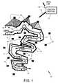
- Fig. 1shows a multiple participant moving vehicle shooting gallery system 10 in accordance with the present invention.
- the system 10comprises a travel path 11 or track 11, a plurality of vehicles 12, a plurality of projectors 13, a plurality of translucent projection screens 14, a plurality of story line images 15 projected onto the screens illustrated by various shading in the drawing, a plurality of fixed targets 16, and a control station 17.
- Each of the individual story line images 15are represented by a different cross hatching or shading in Fig. 1.
- the fixed targets 16are typically incorporated in the back-projected screens 14.
- the control station 17comprises a computer, a real time graphics computer, and a sound processor, and a data link 18 that communicate with each of the vehicles 12 by way of a transponder located in each of the vehicles 12.
- the control station 17also includes power and control cabling 19 that comprises a power and data network 19, that is coupled to the plurality of projectors 13, the fixed targets 16 and to the track 11 in order to control movement and operation of the plurality of vehicles 12.
- Each of !he vehicles 12is shown having a plurality of simulated cannon weapons 21.
- the plurality of projectors 13are adapted to project images 15 onto the screens 14 in a controlled manner under control of the control station 17.
- the image projectionis achieved so that the particular story line flows along with a corresponding one of the vehicles 12 as it moves along the track 11.
- the story line images 15change at selected time or distance intervals as will be detailed below.
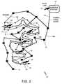
- Fig. 2provides an overview of the power and data network 19 employed in the multiple participant, moving vehicle shooting gallery of Fig. 1.
- Fig. 2provides an overview of the power and data network 19 highlighting the cabling 19a, 19b and data link transponders 22 in each vehicle 12.
- the transponders 22 in the vehicles 12 and the data link 18 in the control station 17may be conventional RF, UHF, or fiber optic type transponders, for example.
- Fig. 3is a system block diagram of the multiple participant, moving vehicle shooting gallery system 10 of Fig. 1.
- the system 10illustrates the central control station 17 which comprises a portion of a sound system that includes a sound processor 24b and a plurality of speakers 26, and a video processor. Both processors 24a, 24b are controlled by a computer 23.
- the control stationalso includes an end-of-ride display 27 whose output is controlled by the computer 23.
- Fig. 3shows the electrical and mechanical components of the vehicle 12, its actuators 25, and simulated cannon weapons 21.
- the relationship between the vehicle 12, the projection screens 14, the projectors 13, and the fixed targets 16is illustrated.
- the fixed targets 16may be masked by off-axis covers 28, comprising louvered plastic, such as Lexan, for example, much like the lenses on traffic lights.
- the relationship between the fixed targets 16, the projection screens 14 and the projectors 13is illustrated.
- Data communicated by way of the data data link 18 to and from the transponder 22 in the vehicleis shown.
- the data that is typically communicated between the vehicles 12 and the central station 17include: weapon number, target number (hit or miss), sound cues, vehicle number vehicle actuator movement data and vehicle location data. This data is processed in a conventional manner to control the movement of the vehicle 12 and the actuators 25, and process and display target engagement information for each of the vehicles 12.
- the vehicle 12comprises the plurality of simulated cannon weapons 21, typically arranged back-to-back, with a total of eight cannon weapons per vehicle 12, for example.
- the plurality of actuators 25are disposed relative to seats in which the participants sit and are adapted to move the vehicle an-or seats in response to occurrences in the story line and hits and missis as a result of firing the simulated cannon weapon 21.
- the control station 17comprises a computer 23, that is coupled to a video processor 24a and a sound processor 24b, and the data link 18.
- the control station 17communicates by means of a transponder 29 with each of the vehicles 12 by way of the transponder 22 located in each of the vehicles 12.
- the control station 17also includes the end-of-ride display 27 that is adapted to provide scoring information and rewards or prizes to the passengers at the end of the ride.
- Fig. 4a-4cshow top, side and rear views of the simulated laser cannon weapon 21 employed in the multiple participant, moving vehicle shooting 10 gallery of Fig. 1.
- the simulated cannon weapon 21comprises a pedestal 39 through which a cable 19c passes that is part of the power and data network 19 is passed to provide power and scoring information.
- the simulated cannon weapon 21includes a scoring mechanism 36 or shot counter, a photo diode 31 or a light pens, for example, that is used to simulate a laser beam, and a trigger 37.
- Front and rear sights 40a, 40bare provided for the purpose of aiming the simulated cannon weapon 21. Shot count is displayed on the scoring mechanism 36 on the face of the simulated cannon weapon 21 for the participant to see.
- the cannonmay be reloaded at the discretion of the theme park as an option through the use of appropriate software control.
- Power for the cannon weapon 21is provided by way of the cabling 19c.
- the simulated cannon weapon 21has a range of motion controlled by safety apparatus (stops, for example) and has the ability to turn toward the target.
- the range of motionmay typically be 30 degrees in elevation and 60 degrees in azimuth, for example.
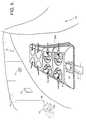
- Fig. 5shows a typical operating embodiment of the multiple participant, moving vehicle shooting gallery system 10 of the present invention.
- the system 10is shown moving along the track 11 within a darkened pathway.
- Two projectors 13are shown located behind the projection screens 14.
- Two fixed targets 16are shown disposed in front of the projection screens 14.
- the transponder 22 located in the vehicle 12is also shown.
- die present inventioncomprises a system 10 that is a moving amusement park ride that requires the travel in die vehicle 12, which may comprise a train, boat, simulated plane, bus, or truck, etc.
- the vehicle 12carries the participants a predetermined distance as they engage simulated targets 16, 16a.
- the participantstravel through a covered and illuminated travel path 11.
- Configuration of die system 10 to provide for specified throughput levelsis left to the selection of the owner, based on the capacity required.
- throughputhas been optimized at 1000 persons per hour with maximum use of central computer processing and control for both scene generation and safety.
- the vehicle 12travels along a predetermined guided length of track 11, for example.
- vehicle propagation techniquesmay be employed, such as by water movement systems, and the like.
- the vehicles 12are dispatched in accordance with a system operation plan that allows for multiple vehicles 12 operating at the same time as throughput requirements dictate. For example, with a track length of 914 m (3000 feet), operating 8 persons per vehicle 12, and a safety factor of 20 sec between cars, at a fixed rate of 7.7 km/hour (4.8 mph), and 85% efficiency, a throughput of 850 participants per hour is achieved using twenty vehicles 12 on the track 11 at any given time.
- Each vehicle 12has an annunciator 22a that is part of its transponder 22 that provides continual broadcasts of location and game data
- This coordinated dataspecifically locates a moving eyepoint 38 so that portrayed scenes of the story line images 15 are made geometrically correct from the participants viewpoint. This also gives die illusion of 3-D depth through perspective and parallax effects.
- Each participanthas a specified field-of-play, defined by the participant's field of view, whereby a participant using the simulated cannon weapon 22 engages die simulated targets 16a that are provided by computer generated images 15 displayed on the back-projected projection screens 14.
- the fixed targets 16are images that are generated in front of the projection screens 14.
- targets 16there are two types of targets: fixed 16 and pop-up 16a. All fixed targets 16 may be masked by the off-axis covers or lenses 28, much like the lenses on traffic lights. The covers create a parallax phenomena and are engaged only in very narrow fields of play. Therefore, scoring is higher, giving die participants the feeling that they had achieved a difficult objective.
- Pop-up or moving targets 16aare featured as part of the back-projected video story and may be engaged by several of the participants simultaneously.
- the targets 16, 16aare successfully engaged when the photo diode 31 (simulated laser beam) detects specifically predetermined pixels of the action sequence (located at the targets 16a) on the screen 14, or from the lighted areas of the fixed targets 16.
- the cannon weapon 21activates a scoring mechanism 36 or shot counter when an aim point 35 of the photo diode 31 (simulated laser beam) fits within a specified field of detection and a trigger 37 is engaged. Participants are assigned color-coded cannons at the beginning of the ride. In this way, successful engagement of the fixed or pop-up targets 16,16a is shown by a puff of colored smoke corresponding to the color assigned to their weapon 21. Shot count is regulated whereby the participant may run out of shooting capacity before the end of the ride. Shot count is provided on scoring mechanism 36 or shot counter on the face of the simulated cannon weapon 21 for the participant to see. Power for the vehicle 12 is provided from the track 11 by way of cabling 19c in a manner substantially similar to conventional bumper cars.
- the vehicle 12travels at 7.7 km/hour (4.8 mph)(akin to a slow trot) by its own electric motor 32.
- the system 10is subject to motion cueing changes in pitch and roll induced by the story line through air actuators 25 installed at the comers of each vehicle 12. There are numerous curves along the track 11 to maximize usage of limited real estate.
- Safety sensors 33ensure crash avoidance and easy slowing for turns, and for stopping at the end of the ride.
- Data from the system 10is gathered in real-time from the cannon weapons 21, passed through the cabling 19 or a fiber-optic network to the transmitter portion of the transponder 22 installed on the vehicle 12.
- Datawhich includes vehicle 12, cannon 21, and target identification, assigned color, vehicle location, hit/miss, shot count, and sound cue is then transmitted to a receiver portion of the transponder 29 at the central data and control processing center 17 whereby real-time effects are induced into the computer generated story.
- vehicle scoresare calculated and summarized for display at the end of the ride. Individual scores are summarized at the end of the ride at the cannon weapon 21 and, by use of a cash register type system, printed onto a card that is dispensed before the participant releases his or her safety belt. The summary score for the vehicle 12, displayed at the end of the ride, is identified to that vehicle 12 by the broadcast.
- the present inventionprovides vehicle seating for a selected number of passengers, each of which operate the simulated laser cannon weapon 21 and interactively engage the targets 16, 16a during a 410 sec (approximately 7 min) ride through varying simulated environments.
- the participantsscore points for each successful engagement of varying fixed and scenario driven pop-up targets 16, 16a.
- the total score of the ride, and/or individual scoresare displayed for all participants to see. Relative merit is also displayed, relating to standard values, such as: 1000 or more points equals a gold medal or free trip to another ride, 999-850 allows the crew passage on a selected ride, etc.
- the projection systemcomprising the projectors 13 and projection screens 14, is an adaptation of an invention disclosed in EP-A-0282504.
- the storiesare displayed by use of a system providing computer generated video images to strategically placed projectors 13 throughout the ride.
- the imagesare displayed on a rear projection faceted dome which uses a translucent rear-projection screen 14.
- Each screen 14is overlapping in which distortion effects are easily corrected and edge matching is easily implemented.
- the method for projection of the computer generated video in a manner to provide low cost maximum coverage in a low light conditionis contained in the above-cited patent application, which is incorporated herein by reference.
- Sound cuesare fed, via the data link, to strategically located speakers 26 adapted with an sound system known as SRS, developed by the assignee of the present invention, thus providing 3-D directional sound effects. Provisions are made that locate the speakers within each vehicle 12 at the request of the customer (theme park operator).
- Sample scenarioThe following is what a participant experiences in the first part of the ride. For 56 seconds the participant is exposed to a back projection computed generated story of attacking jungle or generic animals and various environmental threats, such as falling trees, flying volcanic rocks, etc. The participant senses motion of the vehicle 12 and the passing of reference points in the projected story. Fixed targets 16 which are hidden by off-axis lens 28 are exposed for a short time as the vehicle 12 travelled pass the lens 28 allowing the participants to engage them. For each pull of the trigger, a shot count is recorded and the participant is alerted to the shots-left during the course of the game.
Landscapes
- Engineering & Computer Science (AREA)
- Theoretical Computer Science (AREA)
- Business, Economics & Management (AREA)
- General Engineering & Computer Science (AREA)
- Aviation & Aerospace Engineering (AREA)
- Radar, Positioning & Navigation (AREA)
- Multimedia (AREA)
- Physics & Mathematics (AREA)
- Educational Administration (AREA)
- Educational Technology (AREA)
- General Physics & Mathematics (AREA)
- Aiming, Guidance, Guns With A Light Source, Armor, Camouflage, And Targets (AREA)
- Processing Or Creating Images (AREA)
Description
- The present invention relates generally to theme park rides and, more particularly, to a multiple participant moving vehicle shooting gallery system employing simulated computer-generated interactive video.
- Shooting gallery type activities are not new to the entertainment business, and certainly not to the amusement park industry. In recent years, shopping malls have become a location of amusement park type attractions with both iron rides, such as roller coasters, and the like, and dark rides, such as roller coasters located within buildings, wherein the passengers ride in the dark. The advent of these attractions, first installed in the Edmonton, Alberta, Canada Shopping Mall, launched a new concept called a family entertainment center.
- EP-A-0420277 describes a moving vehicle shooting gallery system having a plurality of game stages including a travel path extending through the respective game stages. A carrier is provided for receiving a player or players thereon and for moving along the travel path while causing the player to play a game at each of the game stages. A score processor is provided for processing the score of the player. A representing device is provided for representing the game in each of the game stages and which provides a multi-story game by changing the game representation mode at a game stage through which the carrier is moving or will move, depending on the total carrier score won by the player. A plurality of fixed targets are provided along the travel path which are activated by light emitting weapons operated by the player. An infrared communication link is provided between each vehicle and a control center.
- DE-A-3523459 discloses a projected image weapon training apparatus for training the reaction of trainees in an enclosed room that has a wall formed by a screen onto which an image is back projected by a projector. Each trainee's weapon has a light emitter responsive to firing the weapon at the screen to simulate the projectile impact point. A television camera is disposed adjacent to the projector and views the rear of the screen. The camera views the projectile impact point and relates the position of the point within the camera field of view to datum points of the projected image. the datum points are visible to the camera and not to the trainee. The scoring is analyzed by projecting onto the screen recorded video images including both the projectile impact point and the reflected projected image and a memory containing the positional relationships between datum points and target areas may be used with an image processor to determine quantitative relationships between simulated impact points and the target area.
- However, heretofore, no conventional amusement park type ride has employed a system wherein participants move through a simulated environment and conduct interactive engagements with simulated weapons. Furthermore, no conventional amusement park type ride has provided a varying range of experiences by the nature of changing visual environments, and pseudo teamwork based upon hitting targets.
- It is therefore an objective of the present invention to provide an interactive, moving, shooting arcade-like game, using various game scenarios whereby participants score virtual hits on targets as they travel the length of the course, by using simulated laser weapons. Another objective of the invention is to provide a ride suitable for use in a theme park, amusement park, or a family entertainment center.
- The present invention provides a multiple participant moving vehicle shooting gallery system comprising:
an enclosure defining a darkened path;
a track adapted to move a plurality of vehicles through the darkened path within the enclosure;
at least one vehicle disposed on the track, said at least one vehicle comprising means for seating a participant, a simulated weapon that is actuable by the participant and which comprises a photo diode adapted to detect predetermined light levels located in projected images that are indicative of a hit on a target, and first communication means for communicating data and control information to and from the vehicle;
a projection system comprising a plurality of rear-screen projectors and plurality of speakers disposed adjacent the track, and a plurality of projection screens disposed adjacent the track between the projectors and the vehicle, and wherein the projectors are adapted to project images onto the screens that comprise the simulated moving targets, and wherein the plurality of speakers are adapted to project sound in conjunction with the projected images; and
a control station, comprising a computer, a video processor, a sound system including a sound processor and the plurality of speakers, second communication means for communicating data and control information to the first communication means in the vehicle, said control station being adapted to: (a) control an adjustable game scenario comprising a story line, wherein said adjustable game scenario comprises a plurality of scenes, each scene comprising images and sounds, including images and sounds representative of the simulated moving targets, and being projected on a different projection screen, including varying the order of the playing of the scenes on said projection screens; (b) control the movement of the vehicle along the track; and (c) process hits and misses scored by the participant in response to operation of the weapon. - The system may also include a plurality of fixed targets disposed adjacent the track and to the plurality of projection screens that are controllable by the control station. The vehicle may further comprise a plurality of vehicle actuators that are adapted to cause changes in the pitch and roll of the vehicle in response to actuator control signals provided by the control station that correspond to events in the story line and on hits and misses as a result of firing the simulated weapon. The simulated weapon further comprises a laser diode adapted to detect predetermined light levels located in the projected images that are indicative of a hit on the target in the vicinity of the predetermined light levels when a trigger is depressed, and is adapted to generate a signal indicative of hits and misses that is communicable to the central station by the first communication device.
- The present invention comprises a system that requires travel in a vehicle, such as a train, boat, simulated plane, bus, or truck, etc. As such, the vehicle carries the participants a predetermined distance as they engage simulated targets. The travel is through covered and darkened paths. Each participant operates independently of the others and engages targets of opportunity that are displayed during the ride. The participants occupy seats having safety restraints and operate the simulated weapon by sighting it at the targets generated by a computer in accordance with a preselected scenario.
- Vehicles are dispatched in accordance with a system operation plan that allows multiple vehicles operating at the same time as throughput requirements dictate. Each vehicle preferably has a transponder that provides continual broadcasts of location and game data. This coordinated data specifically locates a moving eyepoint so that the portrayed scenes can he made geometrically correct. In this way, images are synchronized to the movement of the vehicles, and whereby the images appear stationary relative to the moving vehicles. This also gives the illusion of 3-D depth through perspective and parallax effects.
- The various features and advantages of the present invention may be more readily understood with reference to the following detailed description taken in conjunction with the accompanying drawings, wherein like reference numerals designate like structural elements, and in which:
- Fig. 1 shows a pictorial diagram of a multiple participant, moving vehicle shooting gallery in accordance with the principles of the present invention;
- Fig. 2 provides an overview of the power and data network employed in the multiple participant, moving vehicle shooting gallery of Fig. 1;
- Fig. 3 is a system block diagram of the multiple participant, moving vehicle shooting gallery of Fig. 1;
- Fig. 4a-4c show several views of a simulated laser cannon employed in the multiple participant, moving vehicle shooting gallery of Fig. 1;
- Fig. 5 shows a typical operating embodiment of the multiple participant, moving vehicle shooting gallery of the present invention.
- Referring to the drawing figures, Fig. 1 shows a multiple participant moving vehicle
shooting gallery system 10 in accordance with the present invention. Thesystem 10 comprises atravel path 11 ortrack 11, a plurality ofvehicles 12, a plurality ofprojectors 13, a plurality of translucent projection screens 14, a plurality ofstory line images 15 projected onto the screens illustrated by various shading in the drawing, a plurality of fixedtargets 16, and acontrol station 17. Each of the individualstory line images 15 are represented by a different cross hatching or shading in Fig. 1. The fixed targets 16 are typically incorporated in the back-projectedscreens 14. - The
control station 17 comprises a computer, a real time graphics computer, and a sound processor, and adata link 18 that communicate with each of thevehicles 12 by way of a transponder located in each of thevehicles 12. Thecontrol station 17 also includes power and control cabling 19 that comprises a power anddata network 19, that is coupled to the plurality ofprojectors 13, the fixedtargets 16 and to thetrack 11 in order to control movement and operation of the plurality ofvehicles 12. Each of !hevehicles 12 is shown having a plurality ofsimulated cannon weapons 21. - The plurality of
projectors 13 are adapted to projectimages 15 onto thescreens 14 in a controlled manner under control of thecontrol station 17. The image projection is achieved so that the particular story line flows along with a corresponding one of thevehicles 12 as it moves along thetrack 11. Thestory line images 15 change at selected time or distance intervals as will be detailed below. - Fig. 2 provides an overview of the power and
data network 19 employed in the multiple participant, moving vehicle shooting gallery of Fig. 1. Fig. 2 provides an overview of the power anddata network 19 highlighting thecabling data link transponders 22 in eachvehicle 12. Thetransponders 22 in thevehicles 12 and the data link 18 in thecontrol station 17 may be conventional RF, UHF, or fiber optic type transponders, for example. - Fig. 3 is a system block diagram of the multiple participant, moving vehicle
shooting gallery system 10 of Fig. 1. Thesystem 10 illustrates thecentral control station 17 which comprises a portion of a sound system that includes asound processor 24b and a plurality ofspeakers 26, and a video processor. Bothprocessors computer 23. The control station also includes an end-of-ride display 27 whose output is controlled by thecomputer 23. - Fig. 3 shows the electrical and mechanical components of the
vehicle 12, itsactuators 25, and simulatedcannon weapons 21. The relationship between thevehicle 12, theprojection screens 14, theprojectors 13, and thefixed targets 16 is illustrated. The fixed targets 16 may be masked by off-axis covers 28, comprising louvered plastic, such as Lexan, for example, much like the lenses on traffic lights. The relationship between the fixedtargets 16, the projection screens 14 and theprojectors 13 is illustrated. Data communicated by way of the data data link 18 to and from thetransponder 22 in the vehicle is shown. The data that is typically communicated between thevehicles 12 and thecentral station 17 include: weapon number, target number (hit or miss), sound cues, vehicle number vehicle actuator movement data and vehicle location data. This data is processed in a conventional manner to control the movement of thevehicle 12 and theactuators 25, and process and display target engagement information for each of thevehicles 12. - More specifically, the
vehicle 12 comprises the plurality ofsimulated cannon weapons 21, typically arranged back-to-back, with a total of eight cannon weapons pervehicle 12, for example. The plurality ofactuators 25 are disposed relative to seats in which the participants sit and are adapted to move the vehicle an-or seats in response to occurrences in the story line and hits and missis as a result of firing thesimulated cannon weapon 21. - The
control station 17 comprises acomputer 23, that is coupled to avideo processor 24a and asound processor 24b, and thedata link 18. Thecontrol station 17 communicates by means of a transponder 29 with each of thevehicles 12 by way of thetransponder 22 located in each of thevehicles 12. Thecontrol station 17 also includes the end-of-ride display 27 that is adapted to provide scoring information and rewards or prizes to the passengers at the end of the ride. - Fig. 4a-4c show top, side and rear views of the simulated
laser cannon weapon 21 employed in the multiple participant, moving vehicle shooting 10 gallery of Fig. 1. Thesimulated cannon weapon 21 comprises apedestal 39 through which acable 19c passes that is part of the power anddata network 19 is passed to provide power and scoring information. Thesimulated cannon weapon 21 includes ascoring mechanism 36 or shot counter, aphoto diode 31 or a light pens, for example, that is used to simulate a laser beam, and atrigger 37. Front andrear sights simulated cannon weapon 21. Shot count is displayed on thescoring mechanism 36 on the face of thesimulated cannon weapon 21 for the participant to see. The cannon may be reloaded at the discretion of the theme park as an option through the use of appropriate software control. Power for thecannon weapon 21 is provided by way of thecabling 19c. Thesimulated cannon weapon 21 has a range of motion controlled by safety apparatus (stops, for example) and has the ability to turn toward the target. The range of motion may typically be 30 degrees in elevation and 60 degrees in azimuth, for example. - Fig. 5 shows a typical operating embodiment of the multiple participant, moving vehicle
shooting gallery system 10 of the present invention. Thesystem 10 is shown moving along thetrack 11 within a darkened pathway. Twoprojectors 13 are shown located behind the projection screens 14. Two fixedtargets 16 are shown disposed in front of the projection screens 14. Thetransponder 22 located in thevehicle 12 is also shown. - More specifically, die present invention comprises a
system 10 that is a moving amusement park ride that requires the travel indie vehicle 12, which may comprise a train, boat, simulated plane, bus, or truck, etc. As such, thevehicle 12 carries the participants a predetermined distance as they engagesimulated targets travel path 11. Configuration ofdie system 10 to provide for specified throughput levels is left to the selection of the owner, based on the capacity required. For descriptive purposes of this disclosure, throughput has been optimized at 1000 persons per hour with maximum use of central computer processing and control for both scene generation and safety. - The
vehicle 12 travels along a predetermined guided length oftrack 11, for example. However, other vehicle propagation techniques may be employed, such as by water movement systems, and the like. Thevehicles 12 are dispatched in accordance with a system operation plan that allows formultiple vehicles 12 operating at the same time as throughput requirements dictate. For example, with a track length of 914 m (3000 feet), operating 8 persons pervehicle 12, and a safety factor of 20 sec between cars, at a fixed rate of 7.7 km/hour (4.8 mph), and 85% efficiency, a throughput of 850 participants per hour is achieved using twentyvehicles 12 on thetrack 11 at any given time. - Each
vehicle 12 has anannunciator 22a that is part of itstransponder 22 that provides continual broadcasts of location and game data This coordinated data specifically locates a moving eyepoint 38 so that portrayed scenes of thestory line images 15 are made geometrically correct from the participants viewpoint. This also gives die illusion of 3-D depth through perspective and parallax effects. - Each participant has a specified field-of-play, defined by the participant's field of view, whereby a participant using the
simulated cannon weapon 22 engages diesimulated targets 16a that are provided by computer generatedimages 15 displayed on the back-projected projection screens 14. The fixed targets 16 are images that are generated in front of the projection screens 14. For the purpose of this description there are two types of targets: fixed 16 and pop-up 16a. All fixedtargets 16 may be masked by the off-axis covers orlenses 28, much like the lenses on traffic lights. The covers create a parallax phenomena and are engaged only in very narrow fields of play. Therefore, scoring is higher, giving die participants the feeling that they had achieved a difficult objective. Pop-up or movingtargets 16a are featured as part of the back-projected video story and may be engaged by several of the participants simultaneously. - The
targets targets 16a) on thescreen 14, or from the lighted areas of the fixed targets 16. Thecannon weapon 21 activates ascoring mechanism 36 or shot counter when anaim point 35 of the photo diode 31 (simulated laser beam) fits within a specified field of detection and atrigger 37 is engaged. Participants are assigned color-coded cannons at the beginning of the ride. In this way, successful engagement of the fixed or pop-uptargets weapon 21. Shot count is regulated whereby the participant may run out of shooting capacity before the end of the ride. Shot count is provided onscoring mechanism 36 or shot counter on the face of thesimulated cannon weapon 21 for the participant to see. Power for thevehicle 12 is provided from thetrack 11 by way ofcabling 19c in a manner substantially similar to conventional bumper cars. - To ensure that in general, participants do not memorize the
system 10, and to give a large variety to the gamesmanship, there are, for example, seven (7) scenarios. Each is projected at the same time to seven different screens/walls, or the like. As the participants move through thesystem 10 they encounter all seven stories. At preselected times, for example, daily, the scenarios rotate to another screen and their sequence changes, as outlined in Table 1 below. The story lines remain the same.Table 1 Story Scramble SCREEN 1 2 3 4 5 6 7 STORY A B C D E F G DAY 1 A B C D E F G DAY 2 B D F A C G E DAY 3 C E G B D A F DAY 4... - The
vehicle 12 travels at 7.7 km/hour (4.8 mph)(akin to a slow trot) by its ownelectric motor 32. Thesystem 10 is subject to motion cueing changes in pitch and roll induced by the story line throughair actuators 25 installed at the comers of eachvehicle 12. There are numerous curves along thetrack 11 to maximize usage of limited real estate.Safety sensors 33 ensure crash avoidance and easy slowing for turns, and for stopping at the end of the ride. - Data from the
system 10 is gathered in real-time from thecannon weapons 21, passed through thecabling 19 or a fiber-optic network to the transmitter portion of thetransponder 22 installed on thevehicle 12. Data, which includesvehicle 12,cannon 21, and target identification, assigned color, vehicle location, hit/miss, shot count, and sound cue is then transmitted to a receiver portion of the transponder 29 at the central data andcontrol processing center 17 whereby real-time effects are induced into the computer generated story. Additionally, vehicle scores are calculated and summarized for display at the end of the ride. Individual scores are summarized at the end of the ride at thecannon weapon 21 and, by use of a cash register type system, printed onto a card that is dispensed before the participant releases his or her safety belt. The summary score for thevehicle 12, displayed at the end of the ride, is identified to thatvehicle 12 by the broadcast. - The present invention provides vehicle seating for a selected number of passengers, each of which operate the simulated
laser cannon weapon 21 and interactively engage thetargets targets - An example of the end-of-ride summary is shown below:
Total Points Prize Arriving Vehicle: Rough-Seas 751 Tar'n Feathers today's high score Cruiser-1 1140 Trip to Stapler Galaxy
Provisions to display the participants name at an "End-of-Ride Display" may be easily adapted and is optional. - Since the entire ride is in a darkened surrounding, dark adaptation for the participants is a feature of a queuing effort. Participants en route to their
vehicles 12 pass through several rooms or pathways (not shown) having continually reduced lighting. During their trip the participants are exposed to the nature and objective of the game through video displays and audio broadcasts. Story lines for pregame activities are the responsibility of the park or fun center, since there also is the opportunity for commercial advertising. By the time the participants reach the game area they will have passed from daylight to dark adaptation. Thus, the ambient brightness of the display is decreased from the brightness level at the beginning of the ride to an efficient level somewhat into the ride. - The projection system, comprising the
projectors 13 and projection screens 14, is an adaptation of an invention disclosed in EP-A-0282504. In the present invention, the stories are displayed by use of a system providing computer generated video images to strategically placedprojectors 13 throughout the ride. The images are displayed on a rear projection faceted dome which uses a translucent rear-projection screen 14. Eachscreen 14 is overlapping in which distortion effects are easily corrected and edge matching is easily implemented. The method for projection of the computer generated video in a manner to provide low cost maximum coverage in a low light condition, is contained in the above-cited patent application, which is incorporated herein by reference. Sound cues are fed, via the data link, to strategically locatedspeakers 26 adapted with an sound system known as SRS, developed by the assignee of the present invention, thus providing 3-D directional sound effects. Provisions are made that locate the speakers within eachvehicle 12 at the request of the customer (theme park operator). - Sample scenario. The following is what a participant experiences in the first part of the ride. For 56 seconds the participant is exposed to a back projection computed generated story of attacking jungle or generic animals and various environmental threats, such as falling trees, flying volcanic rocks, etc. The participant senses motion of the
vehicle 12 and the passing of reference points in the projected story.Fixed targets 16 which are hidden by off-axis lens 28 are exposed for a short time as thevehicle 12 travelled pass thelens 28 allowing the participants to engage them. For each pull of the trigger, a shot count is recorded and the participant is alerted to the shots-left during the course of the game. - As the participant successfully engages the
targets colored cannon weapon 21 are imaged on thescreen 14 in the proximity of thetarget targets 16, the colored puffs of smoke are imaged on thescreens 14 in the general location of the fixedtarget 16. When thetargets vehicle actuators 25 are engaged imparting a motion change as the scenario warrants. For example, the participant engages a flying volcanic rock. As the rock explodes a corresponding shaking of the surrounding atmosphere, and thus a vehicle jerk or jolt occurs. Because thesound system 10 is directive the fragments of the rock appear to pass over the head of the participant and travel to the rear. After the first 56 seconds the participants experience a 3 sec gray-out as they pass from one scenario to the next. This technique continues for each of seven scenarios until the ride ends, approximately 7 minutes after the vehicle leaves the loading platform. - Thus there has been described a new and improved a multiple participant moving vehicle shooting gallery system employing simulated computer-generated interactive video. It is to be understood that the above-described embodiment is merely illustrative of some of the many specific embodiments which represent applications of the principles of the present invention. Clearly, numerous and other arrangements can be readily devised by those skilled in the art without departing from the scope of the invention as defined in the accompanying claims.
Claims (5)
- A multiple participant moving vehicle shooting gallery system (10) comprising:
an enclosure defining a darkened path;
a track (11) adapted to move a plurality of vehicles (12) through the darkened path within the enclosure;
at least one vehicle (12) disposed on the track (11), said at least one vehicle (12) comprising means for seating a participant, a simulated weapon (21) that is actuable by the participant and which comprises a photo diode adapted to detect predetermined light levels located in projected images that are indicative of a hit on a target, and first communication means (22) for communicating data and control information to and from the vehicle (12);
a projection system comprising a plurality of rear-screen projectors (13) and plurality of speakers (26) disposed adjacent the track (11), and a plurality of projection screens (14) disposed adjacent the track between the projectors (13) and the vehicle (12), and wherein the projectors (13) are adapted to project images (15) onto the screens (14) that comprise the simulated moving targets (16a), and wherein the plurality of speakers (26) are adapted to project sound in conjunction with the projected images (15); and
a control station, comprising a computer (23), a video processor (24a), a sound system including a sound processor (24b) and the plurality of speakers (26), second communication means (29) for communicating data and control information to the first communication means (22) in the vehicle (12), said control station (17) being adapted to: (a) control an adjustable game scenario comprising a story line, wherein said adjustable game scenario comprises a plurality of scenes, each scene comprising images (15) and sounds, including images (15) and sounds representative of the simulated moving targets (16), and being projected on a different projection screen (14), including varying the order of the playing of the scenes on said projection screens (14); (b) control the movement of the vehicle (12) along the track (11); and (c) process hits and misses scored by the participant in response to operation of the weapon (21). - A system according to claim 1 which further comprises:
a plurality of fixed targets (16b) disposed adjacent to the track (11) and to the plurality of projection screens (14). - A system according to claim 1 or 2 wherein the vehicle (12) further comprises:
a plurality of vehicle actuators (25) for causing changes in pitch and roll of said vehicle (12) in response to actuator control signals, and said control station (17) is further adapted to generate said actuator control signals in dependence on said story line and on hits and misses as a result of firing the simulated weapon (21). - A system according to claim 1, 2 or 3 wherein the simulated weapon (21) further comprises:
a trigger (37) adapted to fire the simulated weapon (21); and wherein
the laser diode (31) is adapted to detect predetermined light levels located in the projected images (15) that are indicative of a hit on a target (16a) in the vicinity of the predetermined light levels when the trigger (37) is depressed, and the simulated weapon (21) is adapted to generate a signal indicative of hits and misses that is communicable to the central station (17) by the first communication means (22). - A system according to any preceding claim wherein the vehicle (12) further comprises:
a plurality of speakers (22a) disposed adjacent the means for seating the participant.
Applications Claiming Priority (2)
| Application Number | Priority Date | Filing Date | Title |
|---|---|---|---|
| US76384791A | 1991-09-23 | 1991-09-23 | |
| US763847 | 1991-09-23 |
Publications (2)
| Publication Number | Publication Date |
|---|---|
| EP0534712A1 EP0534712A1 (en) | 1993-03-31 |
| EP0534712B1true EP0534712B1 (en) | 1995-12-27 |
Family
ID=25068978
Family Applications (1)
| Application Number | Title | Priority Date | Filing Date |
|---|---|---|---|
| EP92308613AExpired - LifetimeEP0534712B1 (en) | 1991-09-23 | 1992-09-22 | Multiple participant moving vehicle shooting gallery |
Country Status (5)
| Country | Link |
|---|---|
| US (1) | US5382026A (en) |
| EP (1) | EP0534712B1 (en) |
| JP (1) | JPH0793983B2 (en) |
| CA (1) | CA2075122A1 (en) |
| DE (1) | DE69207134T2 (en) |
Families Citing this family (86)
| Publication number | Priority date | Publication date | Assignee | Title |
|---|---|---|---|---|
| US5320358A (en)* | 1993-04-27 | 1994-06-14 | Rpb, Inc. | Shooting game having programmable targets and course for use therewith |
| GB9406621D0 (en)* | 1994-04-05 | 1994-05-25 | Hasbro Int Inc | Electronic toy or game playing apparatus |
| JPH07275511A (en)* | 1994-04-06 | 1995-10-24 | Sega Enterp Ltd | Shooting game system attraction development method |
| US5577733A (en)* | 1994-04-08 | 1996-11-26 | Downing; Dennis L. | Targeting system |
| JP3428151B2 (en)* | 1994-07-08 | 2003-07-22 | 株式会社セガ | Game device using image display device |
| US7077581B2 (en) | 1994-08-02 | 2006-07-18 | Media Technologies Licensing Llc | Imaging system and method |
| US7139843B1 (en) | 1995-05-30 | 2006-11-21 | Roy-G-Biv Corporation | System and methods for generating and communicating motion data through a distributed network |
| US20100131081A1 (en)* | 1995-05-30 | 2010-05-27 | Brown David W | Systems and methods for motion control |
| US7137107B1 (en) | 2003-04-29 | 2006-11-14 | Roy-G-Biv Corporation | Motion control systems and methods |
| US20060206219A1 (en)* | 1995-05-30 | 2006-09-14 | Brown David W | Motion control systems and methods |
| US5691897A (en)* | 1995-05-30 | 1997-11-25 | Roy-G-Biv Corporation | Motion control systems |
| US7301558B2 (en) | 1996-02-27 | 2007-11-27 | Media Technologies Licensing, Llc | Imaging system and method |
| US5785592A (en)* | 1996-08-12 | 1998-07-28 | Sarcos, Inc. | Interactive target game system |
| GB2316472A (en)* | 1996-08-19 | 1998-02-25 | Suzanne Dudley | Tirac Pursue |
| TW357101B (en) | 1996-12-17 | 1999-05-01 | Konami Co Ltd | Shooting video game machine and shooting result presentation method |
| JP3297904B2 (en)* | 1997-01-09 | 2002-07-02 | 株式会社 オーヴァ | Individual recognition device for traveling toys using transponder |
| AU6021398A (en)* | 1997-01-16 | 1998-08-07 | Orlo J. Fiske | Amusement vehicle |
| US6302796B1 (en) | 1997-02-05 | 2001-10-16 | Toymax Inc. | Player programmable, interactive toy for a shooting game |
| US5984788A (en)* | 1997-06-09 | 1999-11-16 | Toymax Inc. | Interactive toy shooting game having a target with a feelable output |
| IL121178A (en) | 1997-06-27 | 2003-11-23 | Nds Ltd | Interactive game system |
| US20010032278A1 (en) | 1997-10-07 | 2001-10-18 | Brown Stephen J. | Remote generation and distribution of command programs for programmable devices |
| JPH11272156A (en)* | 1998-03-25 | 1999-10-08 | Sega Enterp Ltd | Virtual three-dimensional sound image generation apparatus and method and medium |
| US6220965B1 (en) | 1998-07-08 | 2001-04-24 | Universal City Studios Inc. | Amusement system |
| JP3990051B2 (en)* | 1998-10-02 | 2007-10-10 | 株式会社バンダイナムコゲームス | GAME DEVICE AND INFORMATION STORAGE MEDIUM |
| EP1138159B1 (en)* | 1998-12-07 | 2015-06-17 | Universal City Studios LLC | Image correction method to compensate for point of view image distortion |
| US6264555B1 (en)* | 1999-02-05 | 2001-07-24 | Midway Games, Inc. | Amusement game including video displays not related to the game |
| US7749089B1 (en)* | 1999-02-26 | 2010-07-06 | Creative Kingdoms, Llc | Multi-media interactive play system |
| US20060287030A1 (en)* | 1999-02-26 | 2006-12-21 | Briggs Rick A | Systems and methods for interactive game play |
| US8176520B1 (en) | 2000-01-28 | 2012-05-08 | Rockwell Collins, Inc. | Communication system and method for a mobile platform |
| JP4319302B2 (en)* | 1999-10-20 | 2009-08-26 | 株式会社バンダイナムコゲームス | GAME DEVICE AND CHARACTER OPERATION SETTING METHOD |
| US20100131078A1 (en)* | 1999-10-27 | 2010-05-27 | Brown David W | Event driven motion systems |
| US8032605B2 (en)* | 1999-10-27 | 2011-10-04 | Roy-G-Biv Corporation | Generation and distribution of motion commands over a distributed network |
| US6604064B1 (en)* | 1999-11-29 | 2003-08-05 | The United States Of America As Represented By The Secretary Of The Navy | Moving weapons platform simulation system and training method |
| US7599691B1 (en) | 2000-01-28 | 2009-10-06 | Rockwell Collins, Inc. | System and method for internet access on a mobile platform |
| US6741841B1 (en) | 2000-01-28 | 2004-05-25 | Rockwell Collins | Dual receiver for a on-board entertainment system |
| US6761637B2 (en) | 2000-02-22 | 2004-07-13 | Creative Kingdoms, Llc | Method of game play using RFID tracking device |
| US7500917B2 (en)* | 2000-02-22 | 2009-03-10 | Creative Kingdoms, Llc | Magical wand and interactive play experience |
| US7445550B2 (en) | 2000-02-22 | 2008-11-04 | Creative Kingdoms, Llc | Magical wand and interactive play experience |
| US7878905B2 (en) | 2000-02-22 | 2011-02-01 | Creative Kingdoms, Llc | Multi-layered interactive play experience |
| US7066781B2 (en)* | 2000-10-20 | 2006-06-27 | Denise Chapman Weston | Children's toy with wireless tag/transponder |
| WO2002054184A2 (en)* | 2001-01-04 | 2002-07-11 | Roy-G-Biv Corporation | Systems and methods for transmitting motion control data |
| US7904194B2 (en) | 2001-02-09 | 2011-03-08 | Roy-G-Biv Corporation | Event management systems and methods for motion control systems |
| US6796908B2 (en) | 2001-06-14 | 2004-09-28 | Creative Kingdoms, Llc | Interactive dark ride |
| KR20030035670A (en)* | 2001-11-02 | 2003-05-09 | 이애리 | Amusement apparatus applicating the structure of human body |
| US7614958B2 (en)* | 2001-11-16 | 2009-11-10 | Creative Kingdoms, Llc | Interactive quest game |
| DE10209900B4 (en)* | 2002-03-07 | 2004-02-26 | Bke Media Gmbh & Co.Kg | Shooting training system |
| US20040033833A1 (en)* | 2002-03-25 | 2004-02-19 | Briggs Rick A. | Interactive redemption game |
| US6967566B2 (en) | 2002-04-05 | 2005-11-22 | Creative Kingdoms, Llc | Live-action interactive adventure game |
| US20070066396A1 (en) | 2002-04-05 | 2007-03-22 | Denise Chapman Weston | Retail methods for providing an interactive product to a consumer |
| JP2003334382A (en)* | 2002-05-21 | 2003-11-25 | Sega Corp | GAME DEVICE, IMAGE PROCESSING DEVICE, AND IMAGE PROCESSING METHOD |
| US6786830B2 (en) | 2002-06-28 | 2004-09-07 | Koala Corporation | Modular water play structure |
| US7674184B2 (en)* | 2002-08-01 | 2010-03-09 | Creative Kingdoms, Llc | Interactive water attraction and quest game |
| US7029400B2 (en)* | 2002-08-01 | 2006-04-18 | Creative Kingdoms, Llc | Interactive water attraction and quest game |
| US9446319B2 (en) | 2003-03-25 | 2016-09-20 | Mq Gaming, Llc | Interactive gaming toy |
| JP2004302753A (en)* | 2003-03-31 | 2004-10-28 | Public Works Research Institute | River environment image display system |
| RU2283157C2 (en)* | 2003-04-03 | 2006-09-10 | Владимир Алексеевич Гнездилов | Rolling switchback |
| RU2248833C1 (en)* | 2003-06-21 | 2005-03-27 | Гнездилов Владимир Алексеевич | Attraction |
| US8282498B2 (en)* | 2003-08-26 | 2012-10-09 | Publicover Mark W | Play swing systems and methods of play |
| US8027349B2 (en)* | 2003-09-25 | 2011-09-27 | Roy-G-Biv Corporation | Database event driven motion systems |
| US20060064503A1 (en)* | 2003-09-25 | 2006-03-23 | Brown David W | Data routing systems and methods |
| US20070022194A1 (en)* | 2003-09-25 | 2007-01-25 | Brown David W | Database event driven motion systems |
| US20100131077A1 (en)* | 2004-02-25 | 2010-05-27 | Brown David W | Data Collection Systems and Methods for Motion Control |
| US7955168B2 (en)* | 2005-06-24 | 2011-06-07 | Disney Enterprises, Inc. | Amusement ride and video game |
| WO2007047986A1 (en)* | 2005-10-21 | 2007-04-26 | Wisconsin Alumni Research Foundation | Method and system for delivering nucleic acid into a target cell |
| EP2335792B1 (en) | 2006-03-03 | 2014-04-23 | HM Attractions, Inc. | Linear motor driven amusement ride and method of controlling |
| EP2007490A4 (en)* | 2006-04-14 | 2010-07-28 | Creative Kingdoms Llc | Interactive waterplay apparatus and methods |
| US8669845B1 (en) | 2007-03-30 | 2014-03-11 | Vail Resorts, Inc. | RFID skier monitoring systems and methods |
| US8303406B2 (en) | 2008-11-24 | 2012-11-06 | Disney Enterprises, Inc. | System and method for providing an augmented reality experience |
| US20100131947A1 (en)* | 2008-11-24 | 2010-05-27 | Disney Enterprises, Inc. | System and method for enabling a local user of a real-life simulation environment to interact with a remote user of a corresponding virtual environment |
| WO2011126904A2 (en)* | 2010-03-30 | 2011-10-13 | Backyard Leisure Holdings, Inc. | Play system accessory with motion-activated sound module |
| CN102151407A (en)* | 2011-01-27 | 2011-08-17 | 深圳市远望落星山科技有限公司 | Interactive railcar |
| CN103813838B (en) | 2011-06-30 | 2017-02-15 | 哈姆游乐设施股份有限公司 | Motion control system and method for an amusement ride |
| US8578857B2 (en) | 2011-12-08 | 2013-11-12 | Disney Enterprises, Inc. | Amusement park ride with passenger loading separated from vehicle insertion into simulators |
| US11487349B2 (en)* | 2013-11-11 | 2022-11-01 | Whitewater West Industries, Ltd. | Interactive amusement attraction system and method |
| US11960637B2 (en) | 2013-11-11 | 2024-04-16 | Whitewater West Ltd. | Interactive amusement attraction system |
| CN103089037A (en)* | 2013-01-28 | 2013-05-08 | 大连摩尔登科技股份有限公司 | Cinema system for mobile viewing |
| EP2792394B1 (en)* | 2013-04-16 | 2016-07-27 | Jörg Beutler | Interactive speed control |
| US9873058B2 (en)* | 2014-03-18 | 2018-01-23 | Amusement Products Llc | Ride vehicle and amusement attraction |
| CN104225922B (en)* | 2014-10-16 | 2016-03-30 | 芜湖华强文化科技产业有限公司 | A kind of tunnel type amusement device for experiencing |
| CA3133305A1 (en) | 2014-11-17 | 2016-05-17 | Whitewater West Industries Ltd. | Interactive play center with interactive elements and consequence elements |
| EP3183043B1 (en)* | 2014-11-17 | 2019-12-25 | Triotech Amusement Inc. | Gaming method and system for projecting volumetric images onto a physical scene |
| CN105031927B (en)* | 2015-06-09 | 2017-08-25 | 万达文化旅游规划研究院有限公司 | The dark riding and carrying device of hanging type chute interaction class |
| US10099149B2 (en)* | 2015-10-02 | 2018-10-16 | Universal City Studios Llc | Amusement park ride tunnel |
| US10048043B2 (en)* | 2016-07-12 | 2018-08-14 | Paul Rahmanian | Target carrier with virtual targets |
| CA2985748A1 (en) | 2016-11-14 | 2018-05-14 | Whitewater West Industries Ltd. | Play center using structural monoliths for water delivery capabilities |
| CN109876474A (en)* | 2019-02-20 | 2019-06-14 | 北京当红齐天国际文化发展集团有限公司 | A kind of rail mounted viewing system and its control method |
Family Cites Families (12)
| Publication number | Priority date | Publication date | Assignee | Title |
|---|---|---|---|---|
| US3960380A (en)* | 1974-09-16 | 1976-06-01 | Nintendo Co., Ltd. | Light ray gun and target changing projectors |
| GB2029554A (en)* | 1978-09-08 | 1980-03-19 | Brooksby B | Motion picture target apparatus |
| US4349337A (en)* | 1981-07-16 | 1982-09-14 | Pardes Herman I | Marksmanship training system |
| US4680012A (en)* | 1984-07-07 | 1987-07-14 | Ferranti, Plc | Projected imaged weapon training apparatus |
| WO1986005114A1 (en)* | 1985-03-05 | 1986-09-12 | Concorde St. George Productions Pty. Ltd. | Entertainment or amusement structure |
| US4830381A (en)* | 1986-08-15 | 1989-05-16 | Sellner Productions, Inc. | Simulated laser weapon and amusement application therefore |
| NL8802310A (en)* | 1988-09-19 | 1990-04-17 | Vekoma International B V | AMUSEMENT EQUIPMENT. |
| US4976438A (en)* | 1989-03-14 | 1990-12-11 | Namco Ltd. | Multi-player type video game playing system |
| JPH0632700B2 (en)* | 1989-09-29 | 1994-05-02 | 株式会社ナムコ | Amusement device |
| WO1991009268A1 (en)* | 1989-12-11 | 1991-06-27 | Dan Moran | Toy |
| DE3941624A1 (en)* | 1989-12-16 | 1991-06-20 | Nsm Ag | SHOOTING DEVICE |
| JP2564206B2 (en)* | 1990-11-28 | 1996-12-18 | 株式会社セガ・エンタープライゼス | Mobile shooting device |
- 1992
- 1992-07-31CACA002075122Apatent/CA2075122A1/ennot_activeAbandoned
- 1992-09-22EPEP92308613Apatent/EP0534712B1/ennot_activeExpired - Lifetime
- 1992-09-22DEDE69207134Tpatent/DE69207134T2/ennot_activeExpired - Lifetime
- 1992-09-24JPJP4277786Apatent/JPH0793983B2/ennot_activeExpired - Lifetime
- 1994
- 1994-03-17USUS08/210,094patent/US5382026A/ennot_activeExpired - Lifetime
Also Published As
| Publication number | Publication date |
|---|---|
| DE69207134D1 (en) | 1996-02-08 |
| CA2075122A1 (en) | 1993-03-24 |
| US5382026A (en) | 1995-01-17 |
| EP0534712A1 (en) | 1993-03-31 |
| JPH0793983B2 (en) | 1995-10-11 |
| DE69207134T2 (en) | 1996-08-22 |
| JPH06218136A (en) | 1994-08-09 |
Similar Documents
| Publication | Publication Date | Title |
|---|---|---|
| EP0534712B1 (en) | Multiple participant moving vehicle shooting gallery | |
| US5785592A (en) | Interactive target game system | |
| US5239464A (en) | Interactive video system providing repeated switching of multiple tracks of actions sequences | |
| US3960380A (en) | Light ray gun and target changing projectors | |
| US20090280916A1 (en) | Mobile holographic simulator of bowling pins and virtual objects | |
| WO1993016776A1 (en) | Virtual image entertainment | |
| CN202028192U (en) | Interactive entertaining device with visual and acoustic feedback | |
| EP0479422A2 (en) | Theme park attraction for multiple participants using real time simulation | |
| KR20190096841A (en) | System having 3dimensions target for ball sports | |
| US12005341B2 (en) | Interaction of audio, video, effects and architectural lighting with bowling scoring system and methods of use | |
| US20030118971A1 (en) | War game complex and method of playing the game | |
| CN115253310A (en) | Mixed reality dodgem play system | |
| JP2004511748A5 (en) | ||
| Lendino | Attract mode: The rise and fall of coin-op arcade games | |
| US20080125230A1 (en) | Device and Method of Laser Gun Games on Vehicles | |
| GB1352729A (en) | Game machines | |
| JP3238174B2 (en) | Play equipment | |
| JP2564206B2 (en) | Mobile shooting device | |
| JP3878076B2 (en) | game machine | |
| JP3052253B2 (en) | Amusement device and carrier used for the device | |
| JPH07100085B2 (en) | Shooting game device | |
| JP3420871B2 (en) | Game system | |
| EP2049212B1 (en) | System for sport and entertainment | |
| JPH087907Y2 (en) | A simulated gun game machine using a pseudo-stereoscopic device | |
| JP2000140443A (en) | Play device |
Legal Events
| Date | Code | Title | Description |
|---|---|---|---|
| PUAI | Public reference made under article 153(3) epc to a published international application that has entered the european phase | Free format text:ORIGINAL CODE: 0009012 | |
| AK | Designated contracting states | Kind code of ref document:A1 Designated state(s):DE FR GB IT | |
| 17P | Request for examination filed | Effective date:19930908 | |
| 17Q | First examination report despatched | Effective date:19940721 | |
| GRAA | (expected) grant | Free format text:ORIGINAL CODE: 0009210 | |
| AK | Designated contracting states | Kind code of ref document:B1 Designated state(s):DE FR GB IT | |
| REF | Corresponds to: | Ref document number:69207134 Country of ref document:DE Date of ref document:19960208 | |
| ITF | It: translation for a ep patent filed | ||
| ET | Fr: translation filed | ||
| PLBE | No opposition filed within time limit | Free format text:ORIGINAL CODE: 0009261 | |
| 26N | No opposition filed | ||
| REG | Reference to a national code | Ref country code:GB Ref legal event code:732E | |
| REG | Reference to a national code | Ref country code:FR Ref legal event code:TP Ref country code:FR Ref legal event code:CD Ref country code:FR Ref legal event code:CA | |
| REG | Reference to a national code | Ref country code:GB Ref legal event code:IF02 | |
| PGFP | Annual fee paid to national office [announced via postgrant information from national office to epo] | Ref country code:DE Payment date:20100915 Year of fee payment:19 | |
| PGFP | Annual fee paid to national office [announced via postgrant information from national office to epo] | Ref country code:GB Payment date:20110921 Year of fee payment:20 Ref country code:FR Payment date:20110922 Year of fee payment:20 | |
| PGFP | Annual fee paid to national office [announced via postgrant information from national office to epo] | Ref country code:IT Payment date:20110921 Year of fee payment:20 | |
| REG | Reference to a national code | Ref country code:DE Ref legal event code:R071 Ref document number:69207134 Country of ref document:DE | |
| REG | Reference to a national code | Ref country code:DE Ref legal event code:R071 Ref document number:69207134 Country of ref document:DE | |
| REG | Reference to a national code | Ref country code:GB Ref legal event code:PE20 Expiry date:20120921 | |
| PG25 | Lapsed in a contracting state [announced via postgrant information from national office to epo] | Ref country code:DE Free format text:LAPSE BECAUSE OF EXPIRATION OF PROTECTION Effective date:20120925 Ref country code:GB Free format text:LAPSE BECAUSE OF EXPIRATION OF PROTECTION Effective date:20120921 |