EP0534074B1 - Method and instrument for testing the concentration of body fluid constituents - Google Patents
Method and instrument for testing the concentration of body fluid constituentsDownload PDFInfo
- Publication number
- EP0534074B1 EP0534074B1EP92112048AEP92112048AEP0534074B1EP 0534074 B1EP0534074 B1EP 0534074B1EP 92112048 AEP92112048 AEP 92112048AEP 92112048 AEP92112048 AEP 92112048AEP 0534074 B1EP0534074 B1EP 0534074B1
- Authority
- EP
- European Patent Office
- Prior art keywords
- stream
- dialysis
- measuring
- perfusate
- channel
- Prior art date
- Legal status (The legal status is an assumption and is not a legal conclusion. Google has not performed a legal analysis and makes no representation as to the accuracy of the status listed.)
- Expired - Lifetime
Links
- 238000000034methodMethods0.000titleclaimsabstractdescription16
- 210000001124body fluidAnatomy0.000titleclaimsabstractdescription4
- 239000010839body fluidSubstances0.000titleclaimsabstractdescription4
- 239000000470constituentSubstances0.000titleclaimsabstract5
- 238000000502dialysisMethods0.000claimsabstractdescription43
- 108090000790EnzymesProteins0.000claimsabstractdescription36
- 102000004190EnzymesHuman genes0.000claimsabstractdescription36
- 239000012528membraneSubstances0.000claimsabstractdescription30
- JVTAAEKCZFNVCJ-UHFFFAOYSA-Nlactic acidChemical compoundCC(O)C(O)=OJVTAAEKCZFNVCJ-UHFFFAOYSA-N0.000claimsabstractdescription18
- 239000000523sampleSubstances0.000claimsabstractdescription18
- 239000000872bufferSubstances0.000claimsabstractdescription17
- WQZGKKKJIJFFOK-VFUOTHLCSA-Nbeta-D-glucoseChemical compoundOC[C@H]1O[C@@H](O)[C@H](O)[C@@H](O)[C@@H]1OWQZGKKKJIJFFOK-VFUOTHLCSA-N0.000claimsabstractdescription16
- WQZGKKKJIJFFOK-GASJEMHNSA-NGlucoseNatural productsOC[C@H]1OC(O)[C@H](O)[C@@H](O)[C@@H]1OWQZGKKKJIJFFOK-GASJEMHNSA-N0.000claimsabstractdescription13
- 239000008103glucoseSubstances0.000claimsabstractdescription13
- 235000014655lactic acidNutrition0.000claimsabstractdescription9
- 239000004310lactic acidSubstances0.000claimsabstractdescription9
- 229940088598enzymeDrugs0.000claimsdescription34
- BASFCYQUMIYNBI-UHFFFAOYSA-NplatinumSubstances[Pt]BASFCYQUMIYNBI-UHFFFAOYSA-N0.000claimsdescription15
- 239000007788liquidSubstances0.000claimsdescription13
- 239000012530fluidSubstances0.000claimsdescription8
- 108010015776Glucose oxidaseProteins0.000claimsdescription5
- 239000004366Glucose oxidaseSubstances0.000claimsdescription5
- 229940116332glucose oxidaseDrugs0.000claimsdescription5
- 235000019420glucose oxidaseNutrition0.000claimsdescription5
- 229910052697platinumInorganic materials0.000claimsdescription5
- 239000004332silverSubstances0.000claimsdescription4
- 239000000243solutionSubstances0.000claimsdescription4
- 229910000971Silver steelInorganic materials0.000claimsdescription3
- PCHJSUWPFVWCPO-UHFFFAOYSA-NgoldChemical compound[Au]PCHJSUWPFVWCPO-UHFFFAOYSA-N0.000claimsdescription3
- 239000002504physiological saline solutionSubstances0.000claimsdescription3
- 229910001220stainless steelInorganic materials0.000claimsdescription3
- 239000010935stainless steelSubstances0.000claimsdescription3
- 229910019142PO4Inorganic materials0.000claimsdescription2
- NBIIXXVUZAFLBC-UHFFFAOYSA-KphosphateChemical compound[O-]P([O-])([O-])=ONBIIXXVUZAFLBC-UHFFFAOYSA-K0.000claimsdescription2
- 239000010452phosphateSubstances0.000claimsdescription2
- 229920006289polycarbonate filmPolymers0.000claimsdescription2
- 239000003381stabilizerSubstances0.000claimsdescription2
- 230000002572peristaltic effectEffects0.000claims1
- 238000005259measurementMethods0.000abstractdescription13
- 238000011144upstream manufacturingMethods0.000abstractdescription4
- 210000001519tissueAnatomy0.000description18
- 210000004027cellAnatomy0.000description16
- 238000006243chemical reactionMethods0.000description7
- 239000004615ingredientSubstances0.000description7
- QVGXLLKOCUKJST-UHFFFAOYSA-Natomic oxygenChemical compound[O]QVGXLLKOCUKJST-UHFFFAOYSA-N0.000description6
- 229910052760oxygenInorganic materials0.000description6
- 239000001301oxygenSubstances0.000description6
- JVTAAEKCZFNVCJ-UHFFFAOYSA-MLactateChemical compoundCC(O)C([O-])=OJVTAAEKCZFNVCJ-UHFFFAOYSA-M0.000description4
- BQCADISMDOOEFD-UHFFFAOYSA-NSilverChemical compound[Ag]BQCADISMDOOEFD-UHFFFAOYSA-N0.000description3
- 238000009792diffusion processMethods0.000description3
- 230000010412perfusionEffects0.000description3
- 238000010992refluxMethods0.000description3
- 108010073450Lactate 2-monooxygenaseProteins0.000description2
- 230000015572biosynthetic processEffects0.000description2
- 239000003822epoxy resinSubstances0.000description2
- 230000002401inhibitory effectEffects0.000description2
- 239000000463materialSubstances0.000description2
- 230000002503metabolic effectEffects0.000description2
- 230000035699permeabilityEffects0.000description2
- 239000004033plasticSubstances0.000description2
- 229920003023plasticPolymers0.000description2
- 230000010287polarizationEffects0.000description2
- 229920000647polyepoxidePolymers0.000description2
- 239000011148porous materialSubstances0.000description2
- 239000000126substanceSubstances0.000description2
- HWKRAUXFMLQKLS-UHFFFAOYSA-N2-oxidanylidenepropanoic acidChemical compoundCC(=O)C(O)=O.CC(=O)C(O)=OHWKRAUXFMLQKLS-UHFFFAOYSA-N0.000description1
- PHOQVHQSTUBQQK-SQOUGZDYSA-ND-glucono-1,5-lactoneChemical compoundOC[C@H]1OC(=O)[C@H](O)[C@@H](O)[C@@H]1OPHOQVHQSTUBQQK-SQOUGZDYSA-N0.000description1
- LCTONWCANYUPML-UHFFFAOYSA-MPyruvateChemical compoundCC(=O)C([O-])=OLCTONWCANYUPML-UHFFFAOYSA-M0.000description1
- 210000004204blood vesselAnatomy0.000description1
- 239000007853buffer solutionSubstances0.000description1
- 230000007423decreaseEffects0.000description1
- 230000018044dehydrationEffects0.000description1
- 238000006297dehydration reactionMethods0.000description1
- 230000001419dependent effectEffects0.000description1
- 238000011161developmentMethods0.000description1
- 230000018109developmental processEffects0.000description1
- 238000010586diagramMethods0.000description1
- 238000001035dryingMethods0.000description1
- 230000000694effectsEffects0.000description1
- 239000003792electrolyteSubstances0.000description1
- 238000011156evaluationMethods0.000description1
- 210000001723extracellular spaceAnatomy0.000description1
- 238000011049fillingMethods0.000description1
- 229960003681gluconolactoneDrugs0.000description1
- 229910052737goldInorganic materials0.000description1
- 239000010931goldSubstances0.000description1
- XLYOFNOQVPJJNP-ZSJDYOACSA-Nheavy waterSubstances[2H]O[2H]XLYOFNOQVPJJNP-ZSJDYOACSA-N0.000description1
- 238000002513implantationMethods0.000description1
- 238000001727in vivoMethods0.000description1
- 239000003112inhibitorSubstances0.000description1
- 238000009413insulationMethods0.000description1
- 239000012982microporous membraneSubstances0.000description1
- 238000002156mixingMethods0.000description1
- 235000015097nutrientsNutrition0.000description1
- 206010033675panniculitisDiseases0.000description1
- 230000036961partial effectEffects0.000description1
- 229920006264polyurethane filmPolymers0.000description1
- 229940076788pyruvateDrugs0.000description1
- 230000000717retained effectEffects0.000description1
- 230000035945sensitivityEffects0.000description1
- 229910052709silverInorganic materials0.000description1
- 210000004304subcutaneous tissueAnatomy0.000description1
- 230000036962time dependentEffects0.000description1
Images
Classifications
- A—HUMAN NECESSITIES
- A61—MEDICAL OR VETERINARY SCIENCE; HYGIENE
- A61B—DIAGNOSIS; SURGERY; IDENTIFICATION
- A61B5/00—Measuring for diagnostic purposes; Identification of persons
- A61B5/145—Measuring characteristics of blood in vivo, e.g. gas concentration or pH-value ; Measuring characteristics of body fluids or tissues, e.g. interstitial fluid or cerebral tissue
- A61B5/1468—Measuring characteristics of blood in vivo, e.g. gas concentration or pH-value ; Measuring characteristics of body fluids or tissues, e.g. interstitial fluid or cerebral tissue using chemical or electrochemical methods, e.g. by polarographic means
- A61B5/1486—Measuring characteristics of blood in vivo, e.g. gas concentration or pH-value ; Measuring characteristics of body fluids or tissues, e.g. interstitial fluid or cerebral tissue using chemical or electrochemical methods, e.g. by polarographic means using enzyme electrodes, e.g. with immobilised oxidase
- A61B5/14865—Measuring characteristics of blood in vivo, e.g. gas concentration or pH-value ; Measuring characteristics of body fluids or tissues, e.g. interstitial fluid or cerebral tissue using chemical or electrochemical methods, e.g. by polarographic means using enzyme electrodes, e.g. with immobilised oxidase invasive, e.g. introduced into the body by a catheter or needle or using implanted sensors
- A—HUMAN NECESSITIES
- A61—MEDICAL OR VETERINARY SCIENCE; HYGIENE
- A61B—DIAGNOSIS; SURGERY; IDENTIFICATION
- A61B5/00—Measuring for diagnostic purposes; Identification of persons
- A61B5/145—Measuring characteristics of blood in vivo, e.g. gas concentration or pH-value ; Measuring characteristics of body fluids or tissues, e.g. interstitial fluid or cerebral tissue
- A61B5/14525—Measuring characteristics of blood in vivo, e.g. gas concentration or pH-value ; Measuring characteristics of body fluids or tissues, e.g. interstitial fluid or cerebral tissue using microdialysis
- A61B5/14528—Measuring characteristics of blood in vivo, e.g. gas concentration or pH-value ; Measuring characteristics of body fluids or tissues, e.g. interstitial fluid or cerebral tissue using microdialysis invasively
- A—HUMAN NECESSITIES
- A61—MEDICAL OR VETERINARY SCIENCE; HYGIENE
- A61B—DIAGNOSIS; SURGERY; IDENTIFICATION
- A61B5/00—Measuring for diagnostic purposes; Identification of persons
- A61B5/68—Arrangements of detecting, measuring or recording means, e.g. sensors, in relation to patient
- A61B5/6846—Arrangements of detecting, measuring or recording means, e.g. sensors, in relation to patient specially adapted to be brought in contact with an internal body part, i.e. invasive
- A61B5/6847—Arrangements of detecting, measuring or recording means, e.g. sensors, in relation to patient specially adapted to be brought in contact with an internal body part, i.e. invasive mounted on an invasive device
- A61B5/686—Permanently implanted devices, e.g. pacemakers, other stimulators, biochips
Definitions
- the inventionrelates to a method and an arrangement for determining the concentration of ingredients, such as glucose or lactic acid, in tissue fluid, a dialysate stream enriched with the ingredients being produced by means of a dialysis probe which can be implanted in the body tissue and which can be acted upon by a continuous perfusate stream, and which is fed to a measuring arrangement which is preferably arranged extracorporeally becomes.
- ingredientssuch as glucose or lactic acid
- Body tissuesconsist of cells that live in a fluid environment in which nutrients and decay products are transported between the cells and blood vessels.
- concentration of the ingredientsallows conclusions to be drawn about the metabolic state of a patient.
- the concentrationcan be determined, for example, by taking samples from the extracellular space according to the dialysis principle.
- a dialysis probeconsisting of a dialysis membrane and lines for the perfusate flow is inserted into the tissue.
- the perfusate flowing past the membraneis enriched with substances from the tissue fluid and can then be collected and chemically analyzed.
- itis also known to feed the dialysate directly to a measuring arrangement (DE-OS 33 42 170).
- the object of the inventionis to improve the known method of the type mentioned at the outset such that continuous concentration measurements are possible over a longer period of time without re-calibration.
- the solution according to the inventionis based on the knowledge gained in many series of measurements that with the dialysis method with a suitable coordination between membrane permeability, membrane surface and perfusate flow there is only a slight disturbance in the adjacent tissue area, so that the undesired one Dehydration effect is avoided.
- it has been shown above all in the determination of glucose and the determination of lactic acidthat if the electrochemical enzyme cell is immersed directly in the dialysate stream, a time-dependent inhibiting factor is still noticeable, which requires a re-calibration of the measuring circuit containing the enzyme cell within a longer measurement series.
- the dialysate stream in the flow direction upstream of the measuring arrangementis mixed with a buffer stream proportional to the perfusate stream, that the measuring dialysate thus formed is continuously applied to an electrochemical enzyme cell arranged in the measuring arrangement, and that the perfusate stream and the buffer stream can be sucked in from a common liquid reservoir.
- a phosphate-containing pH stabilizeris advantageously added to the buffer stream.
- the perfusion liquid and / or the buffer liquidadvantageously consist of an optionally pH-stabilized physiological saline solution or of Ringer's solution.
- perfusate flowis to be matched to the dialysis membrane surface and its permeability and is expediently between 1 and 5 ⁇ l / min based on a membrane surface of approx. 10 mm2.
- an arrangementwhich contains a dialysis probe which is implantable in body tissue and has the shape of a double-lumen catheter, which is nearby has a closed dialysis membrane at its distal end, and an inflow channel that extends into the membrane area and can be acted upon with a continuous perfusate stream, and an inflow channel that is delimited along a dialysis path to the outside by the dialysis membrane and communicates with the inflow channel at the distal end, preferably with one extracorporeally arranged measuring arrangement connected reflux channel is arranged.
- the measuring arrangementhere has an electrochemical enzyme cell which engages in a flow chamber of the reflux channel, while a bypass channel which can be acted upon with a buffer stream proportional to the perfusate stream opens into the reflux channel in the flow direction, and the inflow channel and the bypass channel on the suction side have a common one Liquid reservoir are connected.
- the enzyme cellhas a measuring electrode preferably made of platinum or gold wire, a reference electrode adjacent to the measuring electrode, preferably made of silver or stainless steel, and an enzyme layer arranged on the electrodes, preferably coated with a semipermeable membrane.
- the enzyme layercan consist, for example, of glucose oxidase (for the determination of ⁇ -D-glucose) or of lactate oxidase (for the determination of lactate).
- An enzyme cell with at least two measuring electrodes coated or uncoated with different enzymes and a common reference electrodecan also be used to carry out combination measurements.
- the various measuring electrodesexpediently engage in separate subchannels of the flow chamber.
- a microporous membraneis advantageously used as the dialysis membrane Polycarbonate film or a polyurethane film with a pore size of approx. 0.01 ⁇ m is used.
- the inflow channel and the bypass channelare each advantageously connected to an elastically flexible suction hose of a common roller metering pump.
- both the inflow channel and the return flow channel in the region of the dialysis probefrom resilient plastic material, the plastic material necessarily being somewhat stiffer than the dialysis membrane should be formed.
- a dialysis probe 10which can be implanted in the subcutaneous tissue
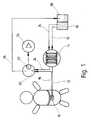
- a perfusion liquidcan be applied via an inflow channel 12, which is sucked out of a liquid reservoir 16 with the aid of a metering pump 14 designed in the exemplary embodiment shown.
- the perfusion liquidconsists, for example, of pH-stabilized physiological saline or Ringer's solution.
- the return flow channel 18 of the dialysis probe 10leads to a flow chamber 20, in which an electrochemical enzyme sensor 22 engages.
- a bypass channel 24is additionally connected to the flow chamber 20 and can be acted upon with a buffer solution directly via the liquid reservoir 16 and the roller metering pump 14.
- the roller metering pump acting jointly on the inflow line 12 and the bypass line 24ensures, using simple means, the setting of a predetermined ratio between the perfusate flow and the buffer flow in accordance with the hose cross-sections used in the pump in the inflow channel and bypass channel.
- the liquid which has previously passed the enzyme sensoris collected and passed via a collecting line 26 into a collecting container 28.
- the dialysis probe 10essentially consists of a cylinder sleeve 34 closed at its proximal and distal end by means of a stopper 30 and 32, which has a dialysis membrane 36 in the region of its distal end and into which through the proximal stopper 30 extends through the inflow channel 12 formed as a thin tube to the distal end.
- the return flow channelwhich is likewise led out at the proximal end, extends via the ring channel 38 to the distal sleeve end and communicates there with the outlet opening 40 of the inflow channel 12.
- the membrane part 36 of the dialysis probe 10is completely embedded in the tissue during its implantation, so that the perfusate flowing in through the inflow channel 12 is loaded with ingredients from the intercellular tissue through the membrane.
- the porosity of the dialysis membrane 36is dimensioned such that the metabolic products to be determined, such as glucose or lactic acid, can enter the perfusate almost without resistance, while larger ingredients are retained.
- the pore sizeis selected at 0.01 to 0.03 ⁇ m.
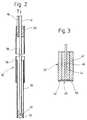
- the enzyme sensor engaging in the flow chamber 20, shown schematically in FIG. 3,essentially consists of a thin cylindrical tube made of silver or stainless steel, which contains an insulating filling 44, for example made of epoxy resin, and an axially aligned measuring electrode 46, preferably made of platinum or gold.
- the metallic tubular jacket 42also forms the reference electrode of the electrochemical sensor.
- the active measuring point 48 of the sensoris located on its end face, on which the measuring electrode 46 protrudes from the epoxy resin insulation 44 and is coated by a semipermeable membrane 50 and an enzyme 52 enclosed within the membrane.
- the reference electrode 42 and the measuring electrode 46are connected to evaluation electronics 54 symbolically shown in FIG. 1, as described, for example, in EP-A-275 390.
- the measurement dialysate which is guided past the enzyme sensor 22 in the flow chamber 20serves as the electrolyte.
- the ⁇ -D-glucose present in the measuring dialysateis oxidized in the presence of oxygen in D-lactones to release H2O2: ⁇ -D-glucose + O2 GOD D-gluconolactone + H2O2
- the formation rate of H2O2can be measured in the electrochemical cell as a diffusion limit current due to the following reaction at the platinum anode: H2O2 Pt O2 + 2H+ + 2e ⁇ .
- the oxygen present in the measurement dialysateis sufficient for the course of the reaction, especially since the oxygen consumed in the glucose conversion is recovered in the conversion of H2O2 at the Pt anode 46 and is at least partially returned to the measurement dialysate.
- lactate present in the measuring dialysateis oxidized in the presence of oxygen in pyruvate (pyruvic acid) with the liberation of H2O2: Lactate + O2 LOD Pyruvate + H2O2.
- the rate of H2O2 formation in the electrochemical cellcan be measured as a diffusion limit current in the sense of the above reaction equation (2) on the platinum anode.
- Both the glucose sensor and the lactate sensormeasure the diffusion limit current with a positive polarization voltage.
- the inventionrelates to a method and an arrangement for the continuous determination of the concentration of ingredients, such as glucose or lactic acid, in body fluids.
- Samplesare taken from the body tissue using the dialysis method.
- a dialysis probe 10is provided which can be implanted in the body tissue and has the shape of a double-lumen catheter and which carries a closed dialysis membrane 26 in the vicinity of its distal end.
- an inflow channel 12which extends inside the dialysis probe 10 and extends into the membrane region and can be acted upon by a continuous perfusate flow
- an outflow channel 18which is delimited along the dialysis path to the outside by the dialysis membrane 36 and which communicates with the inflow channel at the distal end and is connected to a measuring arrangement intended.
- the measuring arrangementhas an electrochemical enzyme cell 20 which engages in a flow chamber of the return flow channel, while in the return flow channel 18 in the flow direction upstream of the enzyme cell 22 a bypass channel 24 which can be acted upon with a buffer stream proportional to the perfusate flow opens and the inflow channel and the bypass channel are connected on the suction side to a common liquid reservoir.
Landscapes
- Life Sciences & Earth Sciences (AREA)
- Health & Medical Sciences (AREA)
- Physics & Mathematics (AREA)
- Medical Informatics (AREA)
- Surgery (AREA)
- Veterinary Medicine (AREA)
- Public Health (AREA)
- Biophysics (AREA)
- Pathology (AREA)
- Engineering & Computer Science (AREA)
- Biomedical Technology (AREA)
- Heart & Thoracic Surgery (AREA)
- General Health & Medical Sciences (AREA)
- Molecular Biology (AREA)
- Animal Behavior & Ethology (AREA)
- Optics & Photonics (AREA)
- Chemical & Material Sciences (AREA)
- Chemical Kinetics & Catalysis (AREA)
- General Chemical & Material Sciences (AREA)
- Apparatus Associated With Microorganisms And Enzymes (AREA)
- Investigating Or Analysing Biological Materials (AREA)
- Measuring Or Testing Involving Enzymes Or Micro-Organisms (AREA)
- External Artificial Organs (AREA)
- Investigating Or Analyzing Non-Biological Materials By The Use Of Chemical Means (AREA)
Abstract
Description
Translated fromGermanDie Erfindung betrifft ein Verfahren und eine Anordnung zur Bestimmung der Konzentration von Inhaltsstoffen, wie Glucose oder Milchsäure, in Gewebeflüssigkeit, wobei mittels einer im Körpergewebe implantierbaren, mit einem kontinuierlichen Perfusatstrom beaufschlagbaren Dialysesonde ein mit den Inhaltsstoffen angereicherter Dialysatstrom erzeugt und einer vorzugsweise extrakorporal angeordneten Meßanordnung zugeleitet wird.The invention relates to a method and an arrangement for determining the concentration of ingredients, such as glucose or lactic acid, in tissue fluid, a dialysate stream enriched with the ingredients being produced by means of a dialysis probe which can be implanted in the body tissue and which can be acted upon by a continuous perfusate stream, and which is fed to a measuring arrangement which is preferably arranged extracorporeally becomes.
Körpergewebe bestehen aus Zellen, die in einer Strömungsmittelumgebung leben, in der Nährstoffe und Zerfallsprodukte zwischen den Zellen und den Blutgefäßen transportiert werden. Die Konzentration der Inhaltsstoffe lassen somit Rückschlüsse auf den Stoffwechselzustand eines Patienten zu. Die Konzentrationsbestimmung kann beispielsweise durch Probenentnahme aus dem extrazellularen Raum nach dem Dialyseprinzip erfolgen. Hierzu wird eine Dialysesonde, die aus einer Dialysemembran und Leitungen für den Perfusatstrom besteht, in das Gewebe eingeführt. Das an der Membran vorbeiströmende Perfusat reichert sich mit Inhaltstoffen aus der Gewebeflüssigkeit an und kann anschließend gesammelt und chemisch analysiert werden. In diesem Zusammenhang ist es auch bereits bekannt, das Dialysat unmittelbar einer Meßanordnung zuzuleiten (DE-OS 33 42 170).Body tissues consist of cells that live in a fluid environment in which nutrients and decay products are transported between the cells and blood vessels. The concentration of the ingredients allows conclusions to be drawn about the metabolic state of a patient. The concentration can be determined, for example, by taking samples from the extracellular space according to the dialysis principle. For this purpose, a dialysis probe consisting of a dialysis membrane and lines for the perfusate flow is inserted into the tissue. The perfusate flowing past the membrane is enriched with substances from the tissue fluid and can then be collected and chemically analyzed. In this context, it is also known to feed the dialysate directly to a measuring arrangement (DE-OS 33 42 170).
Weiter ist es zur Bestimmung des Glucosegehalts in Gewebeflüssigkeit an sich bekannt (EP-A-275 390), eine in die Gewebeflüssigkeit eintauchende elektrochemische Enzymzelle unter Verwendung von Glucoseoxidase als Enzym zu verwenden und den Glucosegehalt aufgrund amperometrischer Messungen zu bestimmen. Umfangreiche Untersuchungen haben jedoch gezeigt, daß die unmittelbar in das Gewebe implantierte Enzymzelle in ihrer Meßempfindlichkeit mit der Zeit stetig abnimmt. Dies wird einmal auf reaktionshemmende Inhibitoren zurückgeführt, die in der Gewebeflüssigkeit enthalten sind und sich in der Enzymzelle ablagern. Zum anderen kann auch eine lokale Austrocknung des Gewebes im Bereich der implantierten Enzymzelle zu einer Verfälschung der Meßergebnisse führen.Furthermore, for the determination of the glucose content in tissue fluid it is known per se (EP-A-275 390) to use an electrochemical enzyme cell immersed in the tissue fluid using glucose oxidase as the enzyme and to determine the glucose content on the basis of amperometric measurements. Extensive studies have shown, however, that the sensitivity of the enzyme cell directly implanted in the tissue steadily decreases over time. This is attributed on the one hand to reaction-inhibiting inhibitors, which are contained in the tissue fluid and are deposited in the enzyme cell. On the other hand, local drying of the tissue in the area of the implanted enzyme cell can also lead to a falsification of the measurement results.
Schließlich ist es an sich bekannt (EP-A 0 104 935), dem Perfusatstrom in Strömungsrichtung vor der Meßanordnung einen Pufferstrom zuzumischen. Allerdings werden bei dem dort beschriebenen Verfahren der Perfusatstrom und die zu untersuchende Substanz mittels einer Mischeinrichtung vermischt, so daß eine in-vivo-Anwendung nicht möglich ist.Finally, it is known per se (EP-A 0 104 935) to add a buffer stream to the perfusate stream in the flow direction upstream of the measuring arrangement. In the method described there, however, the perfusate stream and the substance to be examined are mixed by means of a mixing device, so that in vivo use is not possible.
Ausgehend hiervon liegt der Erfindung die Aufgabe zugrunde, das bekannte Verfahren der eingangs angegebenen Art dahingehend zu verbessern, daß kontinuierliche Konzentrationsmessungen über eine längere Zeit hinweg ohne Nacheichung möglich sind.Proceeding from this, the object of the invention is to improve the known method of the type mentioned at the outset such that continuous concentration measurements are possible over a longer period of time without re-calibration.
Zur Lösung dieser Aufgabe werden die in den Ansprüchen 1 bzw. 6 angegebenen Merkmalskombinationen vorgeschlagen. Weitere vorteilhafte Ausgestaltungen und Weiterbildungen der Erfindung ergeben sich aus den abhängigen Ansprüchen.To achieve this object, the combinations of features specified in claims 1 and 6 are proposed. Further advantageous refinements and developments of the invention result from the dependent claims.
Die erfindungsgemäße Lösung geht von der bei vielen Meßreihen gewonnenen Erkenntnis aus, daß mit der Dialysemethode bei geeigneter Abstimmung zwischen Membrandurchlässigkeit, Membranoberfläche und Perfusatstrom sich nur eine geringe Störung im benachbarten Gewebebereich ergibt, so daß der unerwünschte Austrocknungseffekt vermieden wird. Andererseits hat es sich jedoch vor allem bei der Glucosebestimmung und der Milchsäurebestimmung gezeigt, daß bei unmittelbarem Eintauchen der elektrochemischen Enzymzelle in den Dialysatstrom sich nach wie vor ein zeitabhängiger Hemmfaktor bemerkbar macht, der innerhalb einer längerdauernden Meßserie eine Nacheichung der die Enzymzelle enthaltenden Meßschaltung erfordert. Um dies zu vermeiden, wird nun gemäß der Erfindung vorgeschlagen, daß dem Dialysatstrom in Strömungsrichtung vor der Meßanordnung ein zum Perfusatstrom proportionaler Pufferstrom zugemischt wird, daß mit dem so gebildeten Meßdialysat eine in der Meßanordnung angeordnete elektrochemische Enzymzelle kontinuierlich beaufschlagt wird, und daß der Perfusatstrom und der Pufferstrom aus einem gemeinsamen Flüssigkeitsreservoir angesaugt werden.The solution according to the invention is based on the knowledge gained in many series of measurements that with the dialysis method with a suitable coordination between membrane permeability, membrane surface and perfusate flow there is only a slight disturbance in the adjacent tissue area, so that the undesired one Dehydration effect is avoided. On the other hand, however, it has been shown above all in the determination of glucose and the determination of lactic acid that if the electrochemical enzyme cell is immersed directly in the dialysate stream, a time-dependent inhibiting factor is still noticeable, which requires a re-calibration of the measuring circuit containing the enzyme cell within a longer measurement series. In order to avoid this, it is now proposed according to the invention that the dialysate stream in the flow direction upstream of the measuring arrangement is mixed with a buffer stream proportional to the perfusate stream, that the measuring dialysate thus formed is continuously applied to an electrochemical enzyme cell arranged in the measuring arrangement, and that the perfusate stream and the buffer stream can be sucked in from a common liquid reservoir.
Dem Pufferstrom wird vorteilhafterweise ein phosphathaltiger pH-Stabilisator beigemischt. Vorteilhafterweise bestehen die Perfusionsflüssigkeit und/oder die Pufferflüssigkeit aus einer gegebenenfalls pH-stabilisierten physiologischen Kochsalzlösung oder aus Ringer-Lösung.A phosphate-containing pH stabilizer is advantageously added to the buffer stream. The perfusion liquid and / or the buffer liquid advantageously consist of an optionally pH-stabilized physiological saline solution or of Ringer's solution.
In der praktischen Anwendung hat sich ein Verhältnis zwischen Perfusatstrom und Pufferstrom von 1:0,5 bis 1:3 als optimal erwiesen. Der Perfusatstrom ist dabei auf die Dialysemembran-Oberfläche und deren Durchlässigkeit abzustimmen und beträgt zweckmäßig zwischen 1 und 5 µl/min bezogen auf eine Membranoberfläche von ca. 10 mm².In practical use, a ratio between perfusate flow and buffer flow of 1: 0.5 to 1: 3 has proven to be optimal. The perfusate flow is to be matched to the dialysis membrane surface and its permeability and is expediently between 1 and 5 µl / min based on a membrane surface of approx. 10 mm².
Zur Durchführung des erfindungsgemäßen Verfahrens wird vorteilhafterweise eine Anordnung verwendet, die eine in Körpergewebe implantierbare, die Gestalt eines doppellumigen Katheters aufweisende Dialysesonde enthält, die in der Nähe ihres distalen Endes eine geschlossene Dialysemembran trägt, und innerhalb der ein sich bis in den Membranbereich hinein erstreckender, mit einem kontinuierlichen Perfusatstrom beaufschlagbarer Zuflußkanal und ein entlang einer Dialysestrecke nach außen hin durch die Dialysemembran begrenzter, mit dem Zuflußkanal am distalen Ende kommunizierender, mit einer vorzugsweise extrakorporal angeordneten Meßanordnung verbundener Rückflußkanal angeordnet ist. Erfindungsgemäß weist hierbei die Meßanordnung eine in eine Durchflußkammer des Rückflußkanals eingreifende elektrochemische Enzymzelle auf, während in den Rückflußkanal in Strömungsrichtung vor der Enzymzelle ein mit einem zum Perfusatstrom proportionalen Pufferstrom beaufschlagbarer Bypass-Kanal mündet und wobei der Zuflußkanal und der Bypass-Kanal ansaugseitig mit einem gemeinsamen Flüssigkeitsreservoir verbunden sind.To carry out the method according to the invention, an arrangement is advantageously used which contains a dialysis probe which is implantable in body tissue and has the shape of a double-lumen catheter, which is nearby has a closed dialysis membrane at its distal end, and an inflow channel that extends into the membrane area and can be acted upon with a continuous perfusate stream, and an inflow channel that is delimited along a dialysis path to the outside by the dialysis membrane and communicates with the inflow channel at the distal end, preferably with one extracorporeally arranged measuring arrangement connected reflux channel is arranged. According to the invention, the measuring arrangement here has an electrochemical enzyme cell which engages in a flow chamber of the reflux channel, while a bypass channel which can be acted upon with a buffer stream proportional to the perfusate stream opens into the reflux channel in the flow direction, and the inflow channel and the bypass channel on the suction side have a common one Liquid reservoir are connected.
Eine bevorzugte Ausgestaltung der Erfindung sieht vor, daß die Enzymzelle eine vorzugsweise aus Platin- oder Golddraht bestehende Meßelektrode, eine der Meßelektrode benachbarte, vorzugsweise aus Silber oder Edelstahl bestehende Bezugselektrode, sowie eine auf den Elektroden angeordnete, vorzugsweise mit einer semipermeablen Membran überzogene Enzymschicht aufweist. Je nach Anwendungsfall kann die Enzymschicht beispielsweise aus Glucoseoxidase (zur Bestimmung von β-D-Glucose) oder aus Lactatoxidase (zur Bestimmung von Lactat) bestehen. Zur Durchführung von Kombinationsmessungen kann auch eine Enzymzelle mit mindestens zwei mit unterschiedlichen Enzymen beschichteten oder unbeschichteten Meßelektroden und einer gemeinsamen Bezugselektrode eingesetzt werden. Die verschiedenen Meßelektroden greifen dabei zweckmäßig in getrennte Teilkanäle der Durchflußkammer ein.A preferred embodiment of the invention provides that the enzyme cell has a measuring electrode preferably made of platinum or gold wire, a reference electrode adjacent to the measuring electrode, preferably made of silver or stainless steel, and an enzyme layer arranged on the electrodes, preferably coated with a semipermeable membrane. Depending on the application, the enzyme layer can consist, for example, of glucose oxidase (for the determination of β-D-glucose) or of lactate oxidase (for the determination of lactate). An enzyme cell with at least two measuring electrodes coated or uncoated with different enzymes and a common reference electrode can also be used to carry out combination measurements. The various measuring electrodes expediently engage in separate subchannels of the flow chamber.
Als Dialysemembran wird vorteilhafterweise eine mikroporige Polycarbonatfolie oder eine Polyurethanfolie mit einer Porenweite von ca. 0,01 µm verwendet.A microporous membrane is advantageously used as the dialysis membrane Polycarbonate film or a polyurethane film with a pore size of approx. 0.01 µm is used.
Um eine exakte Proportionalität zwischen Perfusatstrom und Pufferstrom zu erzielen, sind der Zuflußkanal und der Bypass-Kanal vorteilhafterweise mit je einem elastisch nachgiebigen Ansaugschlauch einer gemeinsamen Rollendosierpumpe verbunden.In order to achieve an exact proportionality between perfusate flow and buffer flow, the inflow channel and the bypass channel are each advantageously connected to an elastically flexible suction hose of a common roller metering pump.
Um die durch die Dialysesonde hervorgerufenen Störungen innerhalb des Gewebes so klein wie möglich zu halten, wird gemäß einer vorteilhaften Ausgestaltung der Erfindung vorgeschlagen, sowohl den Zuflußkanal als auch den Rückflußkanal im Bereich der Dialysesonde aus elastisch nachgiebigem Kunststoffmaterial herzustellen, wobei notwendigerweise das Kunststoffmaterial etwas steifer als die Dialysemembran ausgebildet sein sollte.In order to keep the disturbances caused by the dialysis probe within the tissue as small as possible, it is proposed according to an advantageous embodiment of the invention to produce both the inflow channel and the return flow channel in the region of the dialysis probe from resilient plastic material, the plastic material necessarily being somewhat stiffer than the dialysis membrane should be formed.
Im folgenden wird die Erfindung anhand der Zeichnung näher erläutert. Es zeigen
- Fig. 1
- eine schematische Darstellung einer Meßanordnung zur Bestimmung der Konzentration von Inhaltsstoffen in Gewebeflüssigkeit nach der Dialysemethode;
- Fig. 2
- eine Dialysesonde in vergrößerter geschnittener Darstellung;
- Fig. 3
- einen Schnitt durch die Spitze eines Enzymsensors in einer Prinzipdarstellung.
- Fig. 1
- a schematic representation of a measuring arrangement for determining the concentration of ingredients in tissue fluid according to the dialysis method;
- Fig. 2
- a dialysis probe in an enlarged sectional view;
- Fig. 3
- a section through the tip of an enzyme sensor in a schematic diagram.
Die Meßanordnung gemäß Fig. 1 besteht im wesentlichen aus einer im subcutanen Gewebe implantierbaren Dialysesonde 10, die über einen Zuflußkanal 12 mit einer Perfusionsflüssigkeit beaufschlagbar ist, die mit Hilfe einer bei dem gezeigten Ausführungsbeispiel ausgebildeten Dosierpumpe 14 aus einem Flüssigkeitsreservoir 16 angesaugt wird. Die Perfusionsflüssigkeit besteht beispielsweise aus pH-stabilisierter physiologischer Kochsalzlösung oder Ringer-Lösung. Der Rückflußkanal 18 der Dialysesonde 10 führt zu einer Durchflußkammer 20, in die ein elektrochemischer Enzymsensor 22 eingreift. An die Durchflußkammer 20 ist eingangsseitig zusätzlich ein Bypass-Kanal 24 angeschlossen, der unmittelbar über das Flüssigkeitsreservoir 16 und die Rollendosierpumpe 14 mit einer Pufferlösung beaufschlagbar ist. Die auf die Zuflußleitung 12 und die Bypassleitung 24 gemeinsam einwirkende Rollendosierpumpe gewährleistet mit einfachen Mitteln die Einstellung eines vorgegebenen Verhältnisses zwischen Perfusatstrom und Pufferstrom nach Maßgabe der in der Pumpe verwendeten Schlauchquerschnitte im Zuflußkanal und Bypass-Kanal. Am Ausgang der Durchflußkammer wird die zuvor am Enzymsensor vorbeigeleitete Flüssigkeit gesammelt und über eine Sammelleitung 26 in einen Auffangbehälter 28 geleitet.1 essentially consists of a
Wie aus Fig. 2 zu ersehen ist, besteht die Dialysesonde 10 im wesentlichen aus einer an ihrem proximalen und distalen Ende mittels eines Stopfens 30 und 32 verschlossenen Zylinderhülse 34, die im Bereich ihres distalen Endes eine Dialysemembran 36 aufweist und in die durch den proximalen Stopfen 30 hindurch der als dünnes Rohr ausgebildete Zuflußkanal 12 bis zum distalen Ende hindurchgreift. Der gleichfalls am proximalen Ende herausgeführte Rückflußkanal reicht über den Ringkanal 38 bis zum distalen Hülsenende und kommuniziert dort mit der Auslaßöffnung 40 des Zuflußkanals 12.As can be seen from FIG. 2, the
Der Membranteil 36 der Dialysesonde 10 ist bei deren Implantation vollständig in das Gewebe eingebettet, so daß das durch den Zuflußkanal 12 einströmende Perfusat durch die Membran hindurch mit Inhaltsstoffen aus dem interzellularen Gewebe befrachtet wird. Die Porosität der Dialysemembran 36 wird so bemessen, daß die zu bestimmenden Stoffwechselprodukte, wie Glucose oder Milchsäure nahezu widerstandsfrei in das Perfusat gelangen können, während größere Inhaltsstoffe zurückgehalten werden. Zur Glucose- und Milchsäurebestimmung wird die Porenweite bei 0,01 bis 0,03 µm gewählt.The
Der in die Durchflußkammer 20 eingreifende, in Fig. 3 schematisch dargestellte Enzymsensor besteht im wesentlichen aus einem dünnen zylindrischen Rohr aus Silber oder Edelstahl, das eine isolierende Füllung 44, beispielsweise aus Epoxidharz sowie eine axial ausgerichtete Meßelektrode 46, vorzugsweise aus Platin oder Gold enthält. Der metallische Rohrmantel 42 bildet zugleich die Bezugselektrode des elektrochemischen Sensors.The enzyme sensor engaging in the
Die aktive Meßstelle 48 des Sensors befindet sich an dessen Stirnfläche, an der die Meßelektrode 46 aus der Epoxidharz-Isolierung 44 herausragt und von einer semipermeablen Membran 50 und einem innerhalb der Membran eingeschlossenen Enzym 52 beschichtet ist. Die Bezugselektrode 42 und die Meßelekrode 46 sind mit einer in Fig. 1 symbolisch dargestellten Auswerteelektronik 54 verbunden, wie sie beispielsweise in der EP-A-275 390 beschrieben ist.The
Bei der Meßdurchführung dient das in der Durchflußkammer 20 am Enzymsensor 22 vorbeigeführte Meßdialysat als Elektrolyt.When the measurement is carried out, the measurement dialysate which is guided past the
In einem Glucosesensor, der Glucoseoxidase als Enzym 52 enthält, wird im Meßdialysat vorhandene β-D-Glucose im Beisein von Sauerstoff in D-Lactone unter Freisetzung von H₂O₂ oxidiert:

In dem Milchsäuresensor, der Lactatoxidase als Enzym 52 enthält, wird in dem Meßdialysat vorhandenes Lactat im Beisein von Sauerstoff in Pyruvat (Brenztraubensäure) unter Freisetzung von H₂O₂ oxidiert:
Sowohl beim Glucosesensor als auch beim Lactatsensor wird der Diffusionsgrenzstrom mit einer positiven Polarisationsspannung gemessen.Both the glucose sensor and the lactate sensor measure the diffusion limit current with a positive polarization voltage.
Grundsätzlich ist es möglich, den in Fig. 1 gezeigten Sensor auch mit entgegengesetzter Polarisationsspannung, also mit dem Platindraht 46 als Kathode und dem Silberrohr 42 als Anode zu betreiben. Damit erhält man an der Meßelektrode eine Reduktion des im Meßdialysat enthaltenen Sauerstoffs zunächst zu H₂O₂ und anschließend zu H₂O nach folgenden Reaktionsgleichungen:

Zusammenfassend ist folgendes festzustellen: Die Erfindung bezieht sich auf ein Verfahren und eine Anordnung zur kontinuierlichen Bestimmung der Konzentration von Inhaltsstoffen, wie Glucose oder Milchsäure, in Körperflüssigkeiten. Die Probenentnahme aus dem Körpergewebe erfolgt nach dem Dialyseverfahren. Zu diesem Zweck ist eine im Körpergewebe implantierbare, die Gestalt eines doppellumigen Katheters aufweisende Dialysesonde 10 vorgesehen, die in der Nähe ihres distalen Endes eine geschlossene Dialyesmembran 26 trägt. Weiter ist ein sich innerhalb der Dialysesonde 10 bis in den Membranbereich hinein erstreckender, mit einem kontinuierlichen Perfusatstrom beaufschlagbarer Zuflußkanal 12 sowie ein entlang einer Dialysestrecke nach außen hin durch die Dialysemembran 36 begrenzter, mit dem Zuflußkanal am distalen Ende kommunizierender und mit einer Meßanordnung verbundener Rückflußkanal 18 vorgesehen. Um während einer möglichst langen Meßdauer driftfreie Konzentrationsmessungen durchführen zu können, weist die Meßanordnung eine in eine Durchflußkammer des Rückflußkanals eingreifende elektrochemische Enzymzelle 20 auf, während in den Rückflußkanal 18 in Strömungsrichtung vor der Enzymzelle 22 ein mit einem zum Perfusatstrom proportionalen Pufferstrom beaufschlagbarer Bypass-Kanal 24 mündet und wobei der Zuflußkanal und der Bypass-Kanal ansaugseitig mit einem gemeinsamen Flüssigkeitsreservoir verbunden sind.In summary, the following can be stated: The invention relates to a method and an arrangement for the continuous determination of the concentration of ingredients, such as glucose or lactic acid, in body fluids. Samples are taken from the body tissue using the dialysis method. For this purpose, a
Claims (14)
- A process for determining the concentration of constituents, such as glucose or lactic acid, in tissue fluid, in which a dialysate stream enriched with the constituents is formed by means of a dialysis probe (10), which can be supplied with a continuous perfusate stream and can be implanted in body tissue, and is passed into a preferably extracorporeally located measuring arrangement, characterised in that the dialysate stream is mixed with a buffer stream proportional to the perfusate stream in the direction of flow before the measuring arrangement, that an electrochemical enzyme cell (22) located in the measuring arrangement is continuously supplied with the measuring dialysate formed in this way, and that the perfusate stream and the buffer stream are drawn by suction from a common liquid reservoir (16).
- A process according to Claim 1, characterised in that the ratio between perfusate stream and buffer stream is 1:0.5 to 1:3.
- A process according to one of Claims 1 or 2, characterised in that the perfusate stream is 1 to 5 µl/min with respect to ca. 10 mm² of dialysis membrane surface area.
- A process according to one of Claims 1 to 3, characterised in that the buffer stream is mixed with a phosphate-containing pH stabiliser.
- A process according to one of Claims 1 to 4, characterised in that the perfusate and/or the buffer liquid comprises optionally pH stabilised physiological saline solution or Ringer's solution.
- An arrangement for the continuous determination of the concentration of constituents, such as glucose or lactic acid, in body fluids, with a dialysis probe (10) in the form of a double-lumen catheter, which can be implanted in body tissue, which has a sealed dialysis membrane (36) in the vicinity of its distal end, with a supply channel (12) which can be supplied with a continuous perfusate stream extending inside the dialysis probe down to the membrane region and a return channel (18) bounded on the outside along the dialysis section by the dialysis membrane (36), communicating with supply channel (12) at its distal end, connected to a preferably extracorporeally located measuring arrangement, characterised in that the measuring arrangement has an electrochemical enzyme cell (22) inserted into a flow-chamber (20) in the return channel (18), that a by-pass channel (24) which can be supplied with a buffer stream which is proportional to the perfusate stream enters return channel (18) in the direction of flow before the enzyme cell (22), and that the supply channel (12) and the by-pass channel (24) are connected on the suction side to a common liquid reservoir (16)
- An arrangement according to Claim 6, characterised in that the enzyme cell (22) has a measuring electrode (46) preferably consisting of platinum or gold wire, a reference electrode (42), preferably consisting of silver or stainless steel, alongside the measuring electrode (46) and an enzyme layer (32) located on the electrodes, preferably coated with a semipermeable membrane (50).
- An arrangement according to Claim 7, characterised in that the enzyme (52) consists of immobilised glucoseoxidase (GOD).
- An arrangement according to Claim 7, characterised in that the enzyme (52) consists of immobilised lactatoxidase (LOD).
- An arrangement according to one of Claims 6 to 9, characterised in that the enzyme cell (22) has at least two measuring electrodes, coated with different enzymes or uncoated, and a common reference electrode.
- An arrangement according to Claim 10, characterised in that the different measuring electrodes in the enzyme cell are inserted into separate sub-channels in the flow-chamber.
- An arrangement according to one of Claims 6 to 11, characterised in that the dialysis membrane (36) consists of microporous polycarbonate film with a pore-size of ca. 0.01 µm.
- An arrangement according to one of Claims 6 to 12, characterised in that the supply channel (12) and the by-pass channel (24) are each connected to a common peristaltic metering pump (14) with elastically resilient suction tubing.
- An arrangement according to one of Claims 6 to 13, characterised in that the supply channel (12) inside the dialysis probe (10) consists of elastic synthetic tubing.
Applications Claiming Priority (2)
| Application Number | Priority Date | Filing Date | Title |
|---|---|---|---|
| DE4130742ADE4130742A1 (en) | 1991-09-16 | 1991-09-16 | METHOD AND ARRANGEMENT FOR DETERMINING THE CONCENTRATION OF INGREDIENTS IN BODY LIQUIDS |
| DE4130742 | 1991-09-16 |
Publications (2)
| Publication Number | Publication Date |
|---|---|
| EP0534074A1 EP0534074A1 (en) | 1993-03-31 |
| EP0534074B1true EP0534074B1 (en) | 1996-03-06 |
Family
ID=6440704
Family Applications (1)
| Application Number | Title | Priority Date | Filing Date |
|---|---|---|---|
| EP92112048AExpired - LifetimeEP0534074B1 (en) | 1991-09-16 | 1992-07-15 | Method and instrument for testing the concentration of body fluid constituents |
Country Status (3)
| Country | Link |
|---|---|
| EP (1) | EP0534074B1 (en) |
| AT (1) | ATE134851T1 (en) |
| DE (2) | DE4130742A1 (en) |
Cited By (43)
| Publication number | Priority date | Publication date | Assignee | Title |
|---|---|---|---|---|
| US7134999B2 (en) | 2003-04-04 | 2006-11-14 | Dexcom, Inc. | Optimized sensor geometry for an implantable glucose sensor |
| US7192450B2 (en) | 2003-05-21 | 2007-03-20 | Dexcom, Inc. | Porous membranes for use with implantable devices |
| US7226978B2 (en) | 2002-05-22 | 2007-06-05 | Dexcom, Inc. | Techniques to improve polyurethane membranes for implantable glucose sensors |
| US7471972B2 (en) | 2001-07-27 | 2008-12-30 | Dexcom, Inc. | Sensor head for use with implantable devices |
| US7632228B2 (en) | 2001-07-27 | 2009-12-15 | Dexcom, Inc. | Membrane for use with implantable devices |
| US7637868B2 (en) | 2004-01-12 | 2009-12-29 | Dexcom, Inc. | Composite material for implantable device |
| US7657297B2 (en) | 2004-05-03 | 2010-02-02 | Dexcom, Inc. | Implantable analyte sensor |
| US7711402B2 (en) | 1997-03-04 | 2010-05-04 | Dexcom, Inc. | Device and method for determining analyte levels |
| US7715893B2 (en) | 2003-12-05 | 2010-05-11 | Dexcom, Inc. | Calibration techniques for a continuous analyte sensor |
| US7860545B2 (en) | 1997-03-04 | 2010-12-28 | Dexcom, Inc. | Analyte measuring device |
| US7860544B2 (en) | 1998-04-30 | 2010-12-28 | Abbott Diabetes Care Inc. | Analyte monitoring device and methods of use |
| US7875293B2 (en) | 2003-05-21 | 2011-01-25 | Dexcom, Inc. | Biointerface membranes incorporating bioactive agents |
| US7885697B2 (en) | 2004-07-13 | 2011-02-08 | Dexcom, Inc. | Transcutaneous analyte sensor |
| US7896809B2 (en) | 2003-07-25 | 2011-03-01 | Dexcom, Inc. | Dual electrode system for a continuous analyte sensor |
| US7976492B2 (en) | 2004-02-26 | 2011-07-12 | Dexcom, Inc. | Integrated delivery device for continuous glucose sensor |
| US8000901B2 (en) | 2003-08-01 | 2011-08-16 | Dexcom, Inc. | Transcutaneous analyte sensor |
| US8052601B2 (en) | 2003-08-01 | 2011-11-08 | Dexcom, Inc. | System and methods for processing analyte sensor data |
| US8060174B2 (en) | 2005-04-15 | 2011-11-15 | Dexcom, Inc. | Analyte sensing biointerface |
| US8114623B2 (en) | 2005-05-07 | 2012-02-14 | Roche Diagnostics Operations, Inc. | Method for determining glucose concentration in tissue fluid |
| US8155723B2 (en) | 1997-03-04 | 2012-04-10 | Dexcom, Inc. | Device and method for determining analyte levels |
| US8160669B2 (en) | 2003-08-01 | 2012-04-17 | Dexcom, Inc. | Transcutaneous analyte sensor |
| US8167801B2 (en) | 2003-08-22 | 2012-05-01 | Dexcom, Inc. | Systems and methods for replacing signal artifacts in a glucose sensor data stream |
| USRE43399E1 (en) | 2003-07-25 | 2012-05-22 | Dexcom, Inc. | Electrode systems for electrochemical sensors |
| US8275437B2 (en) | 2003-08-01 | 2012-09-25 | Dexcom, Inc. | Transcutaneous analyte sensor |
| US8287454B2 (en) | 1998-04-30 | 2012-10-16 | Abbott Diabetes Care Inc. | Analyte monitoring device and methods of use |
| US8346337B2 (en) | 1998-04-30 | 2013-01-01 | Abbott Diabetes Care Inc. | Analyte monitoring device and methods of use |
| US8465425B2 (en) | 1998-04-30 | 2013-06-18 | Abbott Diabetes Care Inc. | Analyte monitoring device and methods of use |
| US8527026B2 (en) | 1997-03-04 | 2013-09-03 | Dexcom, Inc. | Device and method for determining analyte levels |
| US8548553B2 (en) | 2003-08-01 | 2013-10-01 | Dexcom, Inc. | System and methods for processing analyte sensor data |
| US8612159B2 (en) | 1998-04-30 | 2013-12-17 | Abbott Diabetes Care Inc. | Analyte monitoring device and methods of use |
| US8622905B2 (en) | 2003-08-01 | 2014-01-07 | Dexcom, Inc. | System and methods for processing analyte sensor data |
| US8652043B2 (en) | 2001-01-02 | 2014-02-18 | Abbott Diabetes Care Inc. | Analyte monitoring device and methods of use |
| US8657747B2 (en) | 2003-08-22 | 2014-02-25 | Dexcom, Inc. | Systems and methods for processing analyte sensor data |
| US8688188B2 (en) | 1998-04-30 | 2014-04-01 | Abbott Diabetes Care Inc. | Analyte monitoring device and methods of use |
| US8777853B2 (en) | 2003-08-22 | 2014-07-15 | Dexcom, Inc. | Systems and methods for replacing signal artifacts in a glucose sensor data stream |
| US8792955B2 (en) | 2004-05-03 | 2014-07-29 | Dexcom, Inc. | Transcutaneous analyte sensor |
| US8808228B2 (en) | 2004-02-26 | 2014-08-19 | Dexcom, Inc. | Integrated medicament delivery device for use with continuous analyte sensor |
| US8974386B2 (en) | 1998-04-30 | 2015-03-10 | Abbott Diabetes Care Inc. | Analyte monitoring device and methods of use |
| US9066695B2 (en) | 1998-04-30 | 2015-06-30 | Abbott Diabetes Care Inc. | Analyte monitoring device and methods of use |
| US9282925B2 (en) | 2002-02-12 | 2016-03-15 | Dexcom, Inc. | Systems and methods for replacing signal artifacts in a glucose sensor data stream |
| US9451908B2 (en) | 2006-10-04 | 2016-09-27 | Dexcom, Inc. | Analyte sensor |
| US10610136B2 (en) | 2005-03-10 | 2020-04-07 | Dexcom, Inc. | System and methods for processing analyte sensor data for sensor calibration |
| US10813577B2 (en) | 2005-06-21 | 2020-10-27 | Dexcom, Inc. | Analyte sensor |
Families Citing this family (29)
| Publication number | Priority date | Publication date | Assignee | Title |
|---|---|---|---|---|
| DE4405149C2 (en)* | 1993-02-25 | 1998-11-26 | Daimler Benz Aerospace Ag | Arrangement for determining the concentration of ingredients in body fluids |
| DE4401400A1 (en)* | 1994-01-19 | 1995-07-20 | Ernst Prof Dr Pfeiffer | Method and arrangement for continuously monitoring the concentration of a metabolite |
| US5441481A (en)* | 1994-05-27 | 1995-08-15 | Mishra; Pravin | Microdialysis probes and methods of use |
| DE4426694C2 (en)* | 1994-07-28 | 1998-07-23 | Boehringer Mannheim Gmbh | Device for long-term determination of the content of at least one substance in body fluids |
| DE19612105C2 (en)* | 1996-03-27 | 1998-11-05 | Inst Diabetestechnologie Gemei | Method and arrangement for determining the concentration of a metabolite in biological tissue |
| DE19618597B4 (en) | 1996-05-09 | 2005-07-21 | Institut für Diabetestechnologie Gemeinnützige Forschungs- und Entwicklungsgesellschaft mbH an der Universität Ulm | Method for determining the concentration of tissue glucose |
| DE19822711B4 (en)* | 1998-05-20 | 2006-11-23 | Disetronic Licensing Ag | Sensor system with port body |
| DE19935165A1 (en)* | 1999-07-28 | 2001-02-01 | Roche Diagnostics Gmbh | Method and arrangement for determining the concentration of glucose in a body fluid |
| DE10000823A1 (en)* | 2000-01-12 | 2001-07-19 | Hartwin Hobler | Apparatus for introduction of a gas into a body fluid, a tissue fluid or a culture fluid comprises a channel with a gas outlet opening which is closed by means of gas-permeable barrier element |
| IT1314759B1 (en)* | 2000-05-08 | 2003-01-03 | Menarini Farma Ind | INSTRUMENTATION FOR MEASUREMENT AND CONTROL OF THE CONTENT OF GLUCOSIOLACTATE OR OTHER METABOLITES IN BIOLOGICAL FLUIDS |
| DE10060589B4 (en)* | 2000-12-06 | 2004-02-12 | Institut für Diabetestechnologie Gemeinnützige Forschungs- und Entwicklungsgesellschaft mbH an der Universität Ulm | Method for determining the concentration of a substance in biological liquids |
| US8260393B2 (en) | 2003-07-25 | 2012-09-04 | Dexcom, Inc. | Systems and methods for replacing signal data artifacts in a glucose sensor data stream |
| US20190357827A1 (en) | 2003-08-01 | 2019-11-28 | Dexcom, Inc. | Analyte sensor |
| US7519408B2 (en) | 2003-11-19 | 2009-04-14 | Dexcom, Inc. | Integrated receiver for continuous analyte sensor |
| US20080119703A1 (en) | 2006-10-04 | 2008-05-22 | Mark Brister | Analyte sensor |
| US20140121989A1 (en) | 2003-08-22 | 2014-05-01 | Dexcom, Inc. | Systems and methods for processing analyte sensor data |
| US11633133B2 (en) | 2003-12-05 | 2023-04-25 | Dexcom, Inc. | Dual electrode system for a continuous analyte sensor |
| US8423114B2 (en) | 2006-10-04 | 2013-04-16 | Dexcom, Inc. | Dual electrode system for a continuous analyte sensor |
| EP2301428B1 (en) | 2003-12-09 | 2016-11-30 | Dexcom, Inc. | Signal processing for continuous analyte sensor |
| WO2009048462A1 (en) | 2007-10-09 | 2009-04-16 | Dexcom, Inc. | Integrated insulin delivery system with continuous glucose sensor |
| CN100488444C (en)* | 2004-08-19 | 2009-05-20 | 迪拉莫有限公司 | Micro-analysis system |
| WO2007126380A1 (en)* | 2006-05-02 | 2007-11-08 | Cma/Microdialysis Ab | Microdialysis catheter with fixating means |
| ITFI20060310A1 (en)* | 2006-12-07 | 2008-06-08 | Menarini Farma Ind | PORTABLE DEVICE FOR MEASURING AND CONTROL OF ANALYTES IN BIOLOGICAL FLUIDS. |
| CN101657150B (en)* | 2007-01-26 | 2013-04-03 | 弗洛西恩公司 | Sensor for an analysis system |
| EP2107885A1 (en)* | 2007-01-26 | 2009-10-14 | Diramo A/S | Analysis system with a remote analysing unit |
| WO2008154312A1 (en) | 2007-06-08 | 2008-12-18 | Dexcom, Inc. | Integrated medicament delivery device for use with continuous analyte sensor |
| EP2697650B1 (en) | 2011-04-15 | 2020-09-30 | Dexcom, Inc. | Advanced analyte sensor calibration and error detection |
| US20190120785A1 (en) | 2017-10-24 | 2019-04-25 | Dexcom, Inc. | Pre-connected analyte sensors |
| US11331022B2 (en) | 2017-10-24 | 2022-05-17 | Dexcom, Inc. | Pre-connected analyte sensors |
Family Cites Families (21)
| Publication number | Priority date | Publication date | Assignee | Title |
|---|---|---|---|---|
| US4512348A (en)* | 1981-04-24 | 1985-04-23 | Kabushiki Kaisha Kyoto Daiichi Kagaku | Device for automatically and continuously measuring the constituent parts of blood |
| JPS58198351A (en)* | 1982-05-15 | 1983-11-18 | 株式会社京都第一科学 | Method and apparatus for continuously measuring specific component in diluted liquid |
| JPS5961772A (en)* | 1982-09-28 | 1984-04-09 | ザ・イエロ−・スプリングス・インストルメント・カンパニ−・インコ−ポレ−テツド | Liquid chromatograph enzyme electrode detector |
| SU1113744A1 (en)* | 1982-11-30 | 1984-09-15 | Институт электрохимии АН СССР | Method of determination of glucose concentration in blood in vivo |
| SE434214B (en)* | 1982-12-01 | 1984-07-16 | Carl Urban Ungerstedt | DIALYSIS PROBLEM, INTENDED FOR INFORMATION IN BIOLOGICAL Tissues |
| FI834387A0 (en)* | 1983-11-30 | 1983-11-30 | Labsystems Oy | FOERFARANDE FOER UTSPAEDNING AV VAETSKEPROV |
| DE3524824A1 (en)* | 1985-07-11 | 1987-01-15 | Fresenius Ag | DEVICE FOR SAMPLING AND INFUSION |
| DE3530689A1 (en)* | 1985-08-28 | 1987-03-12 | Siegfried Dipl Phys Stiller | Method for continuous measurement of the haemoglobin concentration in the extracorporeal circulation |
| DE3615973A1 (en)* | 1985-08-28 | 1987-11-19 | Siegfried Dipl Phys Stiller | Method for continuously measuring the haemoglobin concentration in an extracorporeal circulation |
| DE3533024A1 (en)* | 1985-09-16 | 1987-03-26 | Bernhard Dipl Chem Olgemoeller | Method and device for the metering, dilution and deproteinisation of biological fluids |
| DE3616062A1 (en)* | 1986-05-13 | 1987-11-19 | Fresenius Ag | METHOD FOR DETERMINING GAS PARTIAL PRESSURES IN BLOOD AND DEVICE FOR IMPLEMENTING THE METHOD |
| DE3620873A1 (en)* | 1986-06-21 | 1987-12-23 | Rau Guenter | DEVICE FOR DETERMINING THE PARTIAL PRESSURE OF GASES AND GAS MIXTURES SOLVED IN A FLUID |
| SE451894B (en)* | 1986-08-15 | 1987-11-02 | Gambro Ab | ANALYTICAL SYSTEM CONTAINING MEASURES FOR BLOOD SAMPLING, AND FOR CONDUCTING PREVENT A METAL ELECTRODE, AND FOR SUPPLY OF DILUTING OR ANTICOAGULATING FLUID |
| DE3700119A1 (en)* | 1987-01-03 | 1988-07-14 | Inst Diabetestechnologie Gemei | IMPLANTABLE ELECTROCHEMICAL SENSOR |
| DE3806955A1 (en)* | 1987-03-03 | 1988-09-15 | Res Ass Bio Tech Chem | GLUCOSE-SENSITIVE FET SENSOR AND METHOD FOR THE PRODUCTION THEREOF |
| US4974592A (en)* | 1988-11-14 | 1990-12-04 | American Sensor Systems Corporation | Continuous on-line blood monitoring system |
| AT393213B (en)* | 1989-02-08 | 1991-09-10 | Avl Verbrennungskraft Messtech | DEVICE FOR DETERMINING AT LEAST ONE MEDICAL MEASURING SIZE |
| IT1231916B (en)* | 1989-05-29 | 1992-01-15 | Ampliscientifica S R L | WEARABLE ARTIFICIAL PANCREAS |
| FR2648353B1 (en)* | 1989-06-16 | 1992-03-27 | Europhor Sa | MICRODIALYSIS PROBE |
| DE4017868A1 (en)* | 1990-06-02 | 1990-10-31 | Siegfried Dipl Phys Stiller | Mixing chamber - for dilution and haemolysis of blood free from air bubbles |
| DE4028311C1 (en)* | 1990-09-06 | 1991-12-05 | Fresenius Ag, 6380 Bad Homburg, De | Extracorporal blood carbon di:oxide removal arrangement - has feeder line connected to infusion device via which acidic infusion soln. is delivered |
- 1991
- 1991-09-16DEDE4130742Apatent/DE4130742A1/ennot_activeWithdrawn
- 1992
- 1992-07-15ATAT92112048Tpatent/ATE134851T1/ennot_activeIP Right Cessation
- 1992-07-15EPEP92112048Apatent/EP0534074B1/ennot_activeExpired - Lifetime
- 1992-07-15DEDE59205559Tpatent/DE59205559D1/ennot_activeExpired - Fee Related
Cited By (188)
| Publication number | Priority date | Publication date | Assignee | Title |
|---|---|---|---|---|
| US8923947B2 (en) | 1997-03-04 | 2014-12-30 | Dexcom, Inc. | Device and method for determining analyte levels |
| US9339223B2 (en) | 1997-03-04 | 2016-05-17 | Dexcom, Inc. | Device and method for determining analyte levels |
| US7711402B2 (en) | 1997-03-04 | 2010-05-04 | Dexcom, Inc. | Device and method for determining analyte levels |
| US7792562B2 (en) | 1997-03-04 | 2010-09-07 | Dexcom, Inc. | Device and method for determining analyte levels |
| US7835777B2 (en) | 1997-03-04 | 2010-11-16 | Dexcom, Inc. | Device and method for determining analyte levels |
| US7860545B2 (en) | 1997-03-04 | 2010-12-28 | Dexcom, Inc. | Analyte measuring device |
| US8527026B2 (en) | 1997-03-04 | 2013-09-03 | Dexcom, Inc. | Device and method for determining analyte levels |
| US9439589B2 (en) | 1997-03-04 | 2016-09-13 | Dexcom, Inc. | Device and method for determining analyte levels |
| US8155723B2 (en) | 1997-03-04 | 2012-04-10 | Dexcom, Inc. | Device and method for determining analyte levels |
| US8676288B2 (en) | 1997-03-04 | 2014-03-18 | Dexcom, Inc. | Device and method for determining analyte levels |
| US7974672B2 (en) | 1997-03-04 | 2011-07-05 | Dexcom, Inc. | Device and method for determining analyte levels |
| US7970448B2 (en) | 1997-03-04 | 2011-06-28 | Dexcom, Inc. | Device and method for determining analyte levels |
| US8162829B2 (en) | 1998-04-30 | 2012-04-24 | Abbott Diabetes Care Inc. | Analyte monitoring device and methods of use |
| US8224413B2 (en) | 1998-04-30 | 2012-07-17 | Abbott Diabetes Care Inc. | Analyte monitoring device and methods of use |
| US9042953B2 (en) | 1998-04-30 | 2015-05-26 | Abbott Diabetes Care Inc. | Analyte monitoring device and methods of use |
| US9014773B2 (en) | 1998-04-30 | 2015-04-21 | Abbott Diabetes Care Inc. | Analyte monitoring device and methods of use |
| US7885699B2 (en) | 1998-04-30 | 2011-02-08 | Abbott Diabetes Care Inc. | Analyte monitoring device and methods of use |
| US9011331B2 (en) | 1998-04-30 | 2015-04-21 | Abbott Diabetes Care Inc. | Analyte monitoring device and methods of use |
| US8974386B2 (en) | 1998-04-30 | 2015-03-10 | Abbott Diabetes Care Inc. | Analyte monitoring device and methods of use |
| US7860544B2 (en) | 1998-04-30 | 2010-12-28 | Abbott Diabetes Care Inc. | Analyte monitoring device and methods of use |
| US9066697B2 (en) | 1998-04-30 | 2015-06-30 | Abbott Diabetes Care Inc. | Analyte monitoring device and methods of use |
| US9066694B2 (en) | 1998-04-30 | 2015-06-30 | Abbott Diabetes Care Inc. | Analyte monitoring device and methods of use |
| US8880137B2 (en) | 1998-04-30 | 2014-11-04 | Abbott Diabetes Care Inc. | Analyte monitoring device and methods of use |
| US8840553B2 (en) | 1998-04-30 | 2014-09-23 | Abbott Diabetes Care Inc. | Analyte monitoring device and methods of use |
| US8774887B2 (en) | 1998-04-30 | 2014-07-08 | Abbott Diabetes Care Inc. | Analyte monitoring device and methods of use |
| US8744545B2 (en) | 1998-04-30 | 2014-06-03 | Abbott Diabetes Care Inc. | Analyte monitoring device and methods of use |
| US8734346B2 (en) | 1998-04-30 | 2014-05-27 | Abbott Diabetes Care Inc. | Analyte monitoring device and methods of use |
| US8734348B2 (en) | 1998-04-30 | 2014-05-27 | Abbott Diabetes Care Inc. | Analyte monitoring device and methods of use |
| US8738109B2 (en) | 1998-04-30 | 2014-05-27 | Abbott Diabetes Care Inc. | Analyte monitoring device and methods of use |
| US8688188B2 (en) | 1998-04-30 | 2014-04-01 | Abbott Diabetes Care Inc. | Analyte monitoring device and methods of use |
| US9066695B2 (en) | 1998-04-30 | 2015-06-30 | Abbott Diabetes Care Inc. | Analyte monitoring device and methods of use |
| US9072477B2 (en) | 1998-04-30 | 2015-07-07 | Abbott Diabetes Care Inc. | Analyte monitoring device and methods of use |
| US8672844B2 (en) | 1998-04-30 | 2014-03-18 | Abbott Diabetes Care Inc. | Analyte monitoring device and methods of use |
| US8670815B2 (en) | 1998-04-30 | 2014-03-11 | Abbott Diabetes Care Inc. | Analyte monitoring device and methods of use |
| US9326714B2 (en) | 1998-04-30 | 2016-05-03 | Abbott Diabetes Care Inc. | Analyte monitoring device and methods of use |
| US8666469B2 (en) | 1998-04-30 | 2014-03-04 | Abbott Diabetes Care Inc. | Analyte monitoring device and methods of use |
| US8175673B2 (en) | 1998-04-30 | 2012-05-08 | Abbott Diabetes Care Inc. | Analyte monitoring device and methods of use |
| US8177716B2 (en) | 1998-04-30 | 2012-05-15 | Abbott Diabetes Care Inc. | Analyte monitoring device and methods of use |
| US8660627B2 (en) | 1998-04-30 | 2014-02-25 | Abbott Diabetes Care Inc. | Analyte monitoring device and methods of use |
| US8649841B2 (en) | 1998-04-30 | 2014-02-11 | Abbott Diabetes Care Inc. | Analyte monitoring device and methods of use |
| US8641619B2 (en) | 1998-04-30 | 2014-02-04 | Abbott Diabetes Care Inc. | Analyte monitoring device and methods of use |
| US7869853B1 (en) | 1998-04-30 | 2011-01-11 | Abbott Diabetes Care Inc. | Analyte monitoring device and methods of use |
| US8226555B2 (en) | 1998-04-30 | 2012-07-24 | Abbott Diabetes Care Inc. | Analyte monitoring device and methods of use |
| US8226557B2 (en) | 1998-04-30 | 2012-07-24 | Abbott Diabetes Care Inc. | Analyte monitoring device and methods of use |
| US8226558B2 (en) | 1998-04-30 | 2012-07-24 | Abbott Diabetes Care Inc. | Analyte monitoring device and methods of use |
| US8231532B2 (en) | 1998-04-30 | 2012-07-31 | Abbott Diabetes Care Inc. | Analyte monitoring device and methods of use |
| US8235896B2 (en) | 1998-04-30 | 2012-08-07 | Abbott Diabetes Care Inc. | Analyte monitoring device and methods of use |
| US8622906B2 (en) | 1998-04-30 | 2014-01-07 | Abbott Diabetes Care Inc. | Analyte monitoring device and methods of use |
| US8255031B2 (en) | 1998-04-30 | 2012-08-28 | Abbott Diabetes Care Inc. | Analyte monitoring device and methods of use |
| US8260392B2 (en) | 1998-04-30 | 2012-09-04 | Abbott Diabetes Care Inc. | Analyte monitoring device and methods of use |
| US8265726B2 (en) | 1998-04-30 | 2012-09-11 | Abbott Diabetes Care Inc. | Analyte monitoring device and methods of use |
| US8617071B2 (en) | 1998-04-30 | 2013-12-31 | Abbott Diabetes Care Inc. | Analyte monitoring device and methods of use |
| US8273022B2 (en) | 1998-04-30 | 2012-09-25 | Abbott Diabetes Care Inc. | Analyte monitoring device and methods of use |
| US8275439B2 (en) | 1998-04-30 | 2012-09-25 | Abbott Diabetes Care Inc. | Analyte monitoring device and methods of use |
| US8287454B2 (en) | 1998-04-30 | 2012-10-16 | Abbott Diabetes Care Inc. | Analyte monitoring device and methods of use |
| US8612159B2 (en) | 1998-04-30 | 2013-12-17 | Abbott Diabetes Care Inc. | Analyte monitoring device and methods of use |
| US8306598B2 (en) | 1998-04-30 | 2012-11-06 | Abbott Diabetes Care Inc. | Analyte monitoring device and methods of use |
| US8597189B2 (en) | 1998-04-30 | 2013-12-03 | Abbott Diabetes Care Inc. | Analyte monitoring device and methods of use |
| US8346337B2 (en) | 1998-04-30 | 2013-01-01 | Abbott Diabetes Care Inc. | Analyte monitoring device and methods of use |
| US8346336B2 (en) | 1998-04-30 | 2013-01-01 | Abbott Diabetes Care Inc. | Analyte monitoring device and methods of use |
| US8353829B2 (en) | 1998-04-30 | 2013-01-15 | Abbott Diabetes Care Inc. | Analyte monitoring device and methods of use |
| US8357091B2 (en) | 1998-04-30 | 2013-01-22 | Abbott Diabetes Care Inc. | Analyte monitoring device and methods of use |
| US8366614B2 (en) | 1998-04-30 | 2013-02-05 | Abbott Diabetes Care Inc. | Analyte monitoring device and methods of use |
| US8372005B2 (en) | 1998-04-30 | 2013-02-12 | Abbott Diabetes Care Inc. | Analyte monitoring device and methods of use |
| US8380273B2 (en) | 1998-04-30 | 2013-02-19 | Abbott Diabetes Care Inc. | Analyte monitoring device and methods of use |
| US8391945B2 (en) | 1998-04-30 | 2013-03-05 | Abbott Diabetes Care Inc. | Analyte monitoring device and methods of use |
| US8465425B2 (en) | 1998-04-30 | 2013-06-18 | Abbott Diabetes Care Inc. | Analyte monitoring device and methods of use |
| US8480580B2 (en) | 1998-04-30 | 2013-07-09 | Abbott Diabetes Care Inc. | Analyte monitoring device and methods of use |
| US8409131B2 (en) | 1998-04-30 | 2013-04-02 | Abbott Diabetes Care Inc. | Analyte monitoring device and methods of use |
| US8473021B2 (en) | 1998-04-30 | 2013-06-25 | Abbott Diabetes Care Inc. | Analyte monitoring device and methods of use |
| US8668645B2 (en) | 2001-01-02 | 2014-03-11 | Abbott Diabetes Care Inc. | Analyte monitoring device and methods of use |
| US9011332B2 (en) | 2001-01-02 | 2015-04-21 | Abbott Diabetes Care Inc. | Analyte monitoring device and methods of use |
| US8652043B2 (en) | 2001-01-02 | 2014-02-18 | Abbott Diabetes Care Inc. | Analyte monitoring device and methods of use |
| US9498159B2 (en) | 2001-01-02 | 2016-11-22 | Abbott Diabetes Care Inc. | Analyte monitoring device and methods of use |
| US7632228B2 (en) | 2001-07-27 | 2009-12-15 | Dexcom, Inc. | Membrane for use with implantable devices |
| US8840552B2 (en) | 2001-07-27 | 2014-09-23 | Dexcom, Inc. | Membrane for use with implantable devices |
| US7471972B2 (en) | 2001-07-27 | 2008-12-30 | Dexcom, Inc. | Sensor head for use with implantable devices |
| US8509871B2 (en) | 2001-07-27 | 2013-08-13 | Dexcom, Inc. | Sensor head for use with implantable devices |
| US9328371B2 (en) | 2001-07-27 | 2016-05-03 | Dexcom, Inc. | Sensor head for use with implantable devices |
| US9532741B2 (en) | 2001-07-27 | 2017-01-03 | Dexcom, Inc. | Membrane for use with implantable devices |
| US9282925B2 (en) | 2002-02-12 | 2016-03-15 | Dexcom, Inc. | Systems and methods for replacing signal artifacts in a glucose sensor data stream |
| US8865249B2 (en) | 2002-05-22 | 2014-10-21 | Dexcom, Inc. | Techniques to improve polyurethane membranes for implantable glucose sensors |
| US9179869B2 (en) | 2002-05-22 | 2015-11-10 | Dexcom, Inc. | Techniques to improve polyurethane membranes for implantable glucose sensors |
| US7226978B2 (en) | 2002-05-22 | 2007-06-05 | Dexcom, Inc. | Techniques to improve polyurethane membranes for implantable glucose sensors |
| US8050731B2 (en) | 2002-05-22 | 2011-11-01 | Dexcom, Inc. | Techniques to improve polyurethane membranes for implantable glucose sensors |
| US8053018B2 (en) | 2002-05-22 | 2011-11-08 | Dexcom, Inc. | Techniques to improve polyurethane membranes for implantable glucose sensors |
| US7134999B2 (en) | 2003-04-04 | 2006-11-14 | Dexcom, Inc. | Optimized sensor geometry for an implantable glucose sensor |
| US7881763B2 (en) | 2003-04-04 | 2011-02-01 | Dexcom, Inc. | Optimized sensor geometry for an implantable glucose sensor |
| US7875293B2 (en) | 2003-05-21 | 2011-01-25 | Dexcom, Inc. | Biointerface membranes incorporating bioactive agents |
| US7192450B2 (en) | 2003-05-21 | 2007-03-20 | Dexcom, Inc. | Porous membranes for use with implantable devices |
| US8118877B2 (en) | 2003-05-21 | 2012-02-21 | Dexcom, Inc. | Porous membranes for use with implantable devices |
| US7896809B2 (en) | 2003-07-25 | 2011-03-01 | Dexcom, Inc. | Dual electrode system for a continuous analyte sensor |
| USRE43399E1 (en) | 2003-07-25 | 2012-05-22 | Dexcom, Inc. | Electrode systems for electrochemical sensors |
| US8986209B2 (en) | 2003-08-01 | 2015-03-24 | Dexcom, Inc. | Transcutaneous analyte sensor |
| US8394021B2 (en) | 2003-08-01 | 2013-03-12 | Dexcom, Inc. | System and methods for processing analyte sensor data |
| US8160669B2 (en) | 2003-08-01 | 2012-04-17 | Dexcom, Inc. | Transcutaneous analyte sensor |
| US8548553B2 (en) | 2003-08-01 | 2013-10-01 | Dexcom, Inc. | System and methods for processing analyte sensor data |
| US8676287B2 (en) | 2003-08-01 | 2014-03-18 | Dexcom, Inc. | System and methods for processing analyte sensor data |
| US8275437B2 (en) | 2003-08-01 | 2012-09-25 | Dexcom, Inc. | Transcutaneous analyte sensor |
| US8700117B2 (en) | 2003-08-01 | 2014-04-15 | Dexcom, Inc. | System and methods for processing analyte sensor data |
| US8622905B2 (en) | 2003-08-01 | 2014-01-07 | Dexcom, Inc. | System and methods for processing analyte sensor data |
| US8060173B2 (en) | 2003-08-01 | 2011-11-15 | Dexcom, Inc. | System and methods for processing analyte sensor data |
| US8442610B2 (en) | 2003-08-01 | 2013-05-14 | Dexcom, Inc. | System and methods for processing analyte sensor data |
| US8915849B2 (en) | 2003-08-01 | 2014-12-23 | Dexcom, Inc. | Transcutaneous analyte sensor |
| US8052601B2 (en) | 2003-08-01 | 2011-11-08 | Dexcom, Inc. | System and methods for processing analyte sensor data |
| US8761856B2 (en) | 2003-08-01 | 2014-06-24 | Dexcom, Inc. | System and methods for processing analyte sensor data |
| US8206297B2 (en) | 2003-08-01 | 2012-06-26 | Dexcom, Inc. | System and methods for processing analyte sensor data |
| US8774888B2 (en) | 2003-08-01 | 2014-07-08 | Dexcom, Inc. | System and methods for processing analyte sensor data |
| US8000901B2 (en) | 2003-08-01 | 2011-08-16 | Dexcom, Inc. | Transcutaneous analyte sensor |
| US8788007B2 (en) | 2003-08-01 | 2014-07-22 | Dexcom, Inc. | Transcutaneous analyte sensor |
| US8788008B2 (en) | 2003-08-01 | 2014-07-22 | Dexcom, Inc. | System and methods for processing analyte sensor data |
| US8788006B2 (en) | 2003-08-01 | 2014-07-22 | Dexcom, Inc. | System and methods for processing analyte sensor data |
| US8808182B2 (en) | 2003-08-01 | 2014-08-19 | Dexcom, Inc. | System and methods for processing analyte sensor data |
| US8801612B2 (en) | 2003-08-01 | 2014-08-12 | Dexcom, Inc. | System and methods for processing analyte sensor data |
| US8292810B2 (en) | 2003-08-22 | 2012-10-23 | Dexcom, Inc. | Systems and methods for replacing signal artifacts in a glucose sensor data stream |
| US9585607B2 (en) | 2003-08-22 | 2017-03-07 | Dexcom, Inc. | Systems and methods for replacing signal artifacts in a glucose sensor data stream |
| US8435179B2 (en) | 2003-08-22 | 2013-05-07 | Dexcom, Inc. | Systems and methods for replacing signal artifacts in a glucose sensor data stream |
| US8821400B2 (en) | 2003-08-22 | 2014-09-02 | Dexcom, Inc. | Systems and methods for replacing signal artifacts in a glucose sensor data stream |
| US8777853B2 (en) | 2003-08-22 | 2014-07-15 | Dexcom, Inc. | Systems and methods for replacing signal artifacts in a glucose sensor data stream |
| US8195265B2 (en) | 2003-08-22 | 2012-06-05 | Dexcom, Inc. | Systems and methods for replacing signal artifacts in a glucose sensor data stream |
| US8657747B2 (en) | 2003-08-22 | 2014-02-25 | Dexcom, Inc. | Systems and methods for processing analyte sensor data |
| US9510782B2 (en) | 2003-08-22 | 2016-12-06 | Dexcom, Inc. | Systems and methods for replacing signal artifacts in a glucose sensor data stream |
| US9420968B2 (en) | 2003-08-22 | 2016-08-23 | Dexcom, Inc. | Systems and methods for replacing signal artifacts in a glucose sensor data stream |
| US8167801B2 (en) | 2003-08-22 | 2012-05-01 | Dexcom, Inc. | Systems and methods for replacing signal artifacts in a glucose sensor data stream |
| US8412301B2 (en) | 2003-08-22 | 2013-04-02 | Dexcom, Inc. | Systems and methods for replacing signal artifacts in a glucose sensor data stream |
| US8491474B2 (en) | 2003-08-22 | 2013-07-23 | Dexcom, Inc. | Systems and methods for replacing signal artifacts in a glucose sensor data stream |
| US8672845B2 (en) | 2003-08-22 | 2014-03-18 | Dexcom, Inc. | Systems and methods for processing analyte sensor data |
| US8346338B2 (en) | 2003-08-22 | 2013-01-01 | Dexcom, Inc. | System and methods for replacing signal artifacts in a glucose sensor data stream |
| US9149219B2 (en) | 2003-08-22 | 2015-10-06 | Dexcom, Inc. | Systems and methods for replacing signal artifacts in a glucose sensor data stream |
| US7715893B2 (en) | 2003-12-05 | 2010-05-11 | Dexcom, Inc. | Calibration techniques for a continuous analyte sensor |
| US8428678B2 (en) | 2003-12-05 | 2013-04-23 | Dexcom, Inc. | Calibration techniques for a continuous analyte sensor |
| USRE44695E1 (en) | 2003-12-05 | 2014-01-07 | Dexcom, Inc. | Dual electrode system for a continuous analyte sensor |
| US7917186B2 (en) | 2003-12-05 | 2011-03-29 | Dexcom, Inc. | Calibration techniques for a continuous analyte sensor |
| US8483793B2 (en) | 2003-12-05 | 2013-07-09 | Dexcom, Inc. | Dual electrode system for a continuous analyte sensor |
| US8160671B2 (en) | 2003-12-05 | 2012-04-17 | Dexcom, Inc. | Calibration techniques for a continuous analyte sensor |
| US8249684B2 (en) | 2003-12-05 | 2012-08-21 | Dexcom, Inc. | Calibration techniques for a continuous analyte sensor |
| US7637868B2 (en) | 2004-01-12 | 2009-12-29 | Dexcom, Inc. | Composite material for implantable device |
| US8808228B2 (en) | 2004-02-26 | 2014-08-19 | Dexcom, Inc. | Integrated medicament delivery device for use with continuous analyte sensor |
| US7976492B2 (en) | 2004-02-26 | 2011-07-12 | Dexcom, Inc. | Integrated delivery device for continuous glucose sensor |
| US8926585B2 (en) | 2004-02-26 | 2015-01-06 | Dexcom, Inc. | Integrated delivery device for continuous glucose sensor |
| US8721585B2 (en) | 2004-02-26 | 2014-05-13 | Dex Com, Inc. | Integrated delivery device for continuous glucose sensor |
| US8792955B2 (en) | 2004-05-03 | 2014-07-29 | Dexcom, Inc. | Transcutaneous analyte sensor |
| US7657297B2 (en) | 2004-05-03 | 2010-02-02 | Dexcom, Inc. | Implantable analyte sensor |
| US10993641B2 (en) | 2004-07-13 | 2021-05-04 | Dexcom, Inc. | Analyte sensor |
| US10932700B2 (en) | 2004-07-13 | 2021-03-02 | Dexcom, Inc. | Analyte sensor |
| US9414777B2 (en) | 2004-07-13 | 2016-08-16 | Dexcom, Inc. | Transcutaneous analyte sensor |
| US10799158B2 (en) | 2004-07-13 | 2020-10-13 | Dexcom, Inc. | Analyte sensor |
| US11026605B1 (en) | 2004-07-13 | 2021-06-08 | Dexcom, Inc. | Analyte sensor |
| US10980452B2 (en) | 2004-07-13 | 2021-04-20 | Dexcom, Inc. | Analyte sensor |
| US11045120B2 (en) | 2004-07-13 | 2021-06-29 | Dexcom, Inc. | Analyte sensor |
| US11064917B2 (en) | 2004-07-13 | 2021-07-20 | Dexcom, Inc. | Analyte sensor |
| US7885697B2 (en) | 2004-07-13 | 2011-02-08 | Dexcom, Inc. | Transcutaneous analyte sensor |
| US8792953B2 (en) | 2004-07-13 | 2014-07-29 | Dexcom, Inc. | Transcutaneous analyte sensor |
| US10524703B2 (en) | 2004-07-13 | 2020-01-07 | Dexcom, Inc. | Transcutaneous analyte sensor |
| US10993642B2 (en) | 2004-07-13 | 2021-05-04 | Dexcom, Inc. | Analyte sensor |
| US10918313B2 (en) | 2004-07-13 | 2021-02-16 | Dexcom, Inc. | Analyte sensor |
| US10918315B2 (en) | 2004-07-13 | 2021-02-16 | Dexcom, Inc. | Analyte sensor |
| US10918314B2 (en) | 2004-07-13 | 2021-02-16 | Dexcom, Inc. | Analyte sensor |
| US10709362B2 (en) | 2004-07-13 | 2020-07-14 | Dexcom, Inc. | Analyte sensor |
| US10709363B2 (en) | 2004-07-13 | 2020-07-14 | Dexcom, Inc. | Analyte sensor |
| US11883164B2 (en) | 2004-07-13 | 2024-01-30 | Dexcom, Inc. | System and methods for processing analyte sensor data for sensor calibration |
| US10827956B2 (en) | 2004-07-13 | 2020-11-10 | Dexcom, Inc. | Analyte sensor |
| US10722152B2 (en) | 2004-07-13 | 2020-07-28 | Dexcom, Inc. | Analyte sensor |
| US10813576B2 (en) | 2004-07-13 | 2020-10-27 | Dexcom, Inc. | Analyte sensor |
| US10799159B2 (en) | 2004-07-13 | 2020-10-13 | Dexcom, Inc. | Analyte sensor |
| US10918317B2 (en) | 2005-03-10 | 2021-02-16 | Dexcom, Inc. | System and methods for processing analyte sensor data for sensor calibration |
| US10610135B2 (en) | 2005-03-10 | 2020-04-07 | Dexcom, Inc. | System and methods for processing analyte sensor data for sensor calibration |
| US11051726B2 (en) | 2005-03-10 | 2021-07-06 | Dexcom, Inc. | System and methods for processing analyte sensor data for sensor calibration |
| US10716498B2 (en) | 2005-03-10 | 2020-07-21 | Dexcom, Inc. | System and methods for processing analyte sensor data for sensor calibration |
| US10856787B2 (en) | 2005-03-10 | 2020-12-08 | Dexcom, Inc. | System and methods for processing analyte sensor data for sensor calibration |
| US10898114B2 (en) | 2005-03-10 | 2021-01-26 | Dexcom, Inc. | System and methods for processing analyte sensor data for sensor calibration |
| US10918318B2 (en) | 2005-03-10 | 2021-02-16 | Dexcom, Inc. | System and methods for processing analyte sensor data for sensor calibration |
| US10709364B2 (en) | 2005-03-10 | 2020-07-14 | Dexcom, Inc. | System and methods for processing analyte sensor data for sensor calibration |
| US10918316B2 (en) | 2005-03-10 | 2021-02-16 | Dexcom, Inc. | System and methods for processing analyte sensor data for sensor calibration |
| US10617336B2 (en) | 2005-03-10 | 2020-04-14 | Dexcom, Inc. | System and methods for processing analyte sensor data for sensor calibration |
| US10610137B2 (en) | 2005-03-10 | 2020-04-07 | Dexcom, Inc. | System and methods for processing analyte sensor data for sensor calibration |
| US10743801B2 (en) | 2005-03-10 | 2020-08-18 | Dexcom, Inc. | System and methods for processing analyte sensor data for sensor calibration |
| US10925524B2 (en) | 2005-03-10 | 2021-02-23 | Dexcom, Inc. | System and methods for processing analyte sensor data for sensor calibration |
| US10610136B2 (en) | 2005-03-10 | 2020-04-07 | Dexcom, Inc. | System and methods for processing analyte sensor data for sensor calibration |
| US11000213B2 (en) | 2005-03-10 | 2021-05-11 | Dexcom, Inc. | System and methods for processing analyte sensor data for sensor calibration |
| US8060174B2 (en) | 2005-04-15 | 2011-11-15 | Dexcom, Inc. | Analyte sensing biointerface |
| US8114623B2 (en) | 2005-05-07 | 2012-02-14 | Roche Diagnostics Operations, Inc. | Method for determining glucose concentration in tissue fluid |
| US10813577B2 (en) | 2005-06-21 | 2020-10-27 | Dexcom, Inc. | Analyte sensor |
| US8915850B2 (en) | 2005-11-01 | 2014-12-23 | Abbott Diabetes Care Inc. | Analyte monitoring device and methods of use |
| US8920319B2 (en) | 2005-11-01 | 2014-12-30 | Abbott Diabetes Care Inc. | Analyte monitoring device and methods of use |
| US9326716B2 (en) | 2005-11-01 | 2016-05-03 | Abbott Diabetes Care Inc. | Analyte monitoring device and methods of use |
| US9078607B2 (en) | 2005-11-01 | 2015-07-14 | Abbott Diabetes Care Inc. | Analyte monitoring device and methods of use |
| US9451908B2 (en) | 2006-10-04 | 2016-09-27 | Dexcom, Inc. | Analyte sensor |
Also Published As
| Publication number | Publication date |
|---|---|
| DE4130742A1 (en) | 1993-03-18 |
| DE59205559D1 (en) | 1996-04-11 |
| ATE134851T1 (en) | 1996-03-15 |
| EP0534074A1 (en) | 1993-03-31 |
Similar Documents
| Publication | Publication Date | Title |
|---|---|---|
| EP0534074B1 (en) | Method and instrument for testing the concentration of body fluid constituents | |
| EP0273258B1 (en) | Arrangement for the analysis of liquids, and method of applying it | |
| EP0664989B1 (en) | Instrument for continuously monitoring the concentration of a metabolit | |
| DE69025646T2 (en) | Art pancreas | |
| DE3780061T2 (en) | SYSTEM FOR MONITORING BLOOD COMPONENTS. | |
| EP0275390B1 (en) | Implantable electrochemical sensor | |
| DE2927048C2 (en) | Device for performing analytical measurements on a liquid | |
| DE69807042T2 (en) | METHOD FOR CALIBRATING SENSORS IN DIAGNOSTIC TEST METHODS | |
| DE69324376T2 (en) | DEVICE FOR IN-VIVO DETERMINING THE CONCENTRATION OF METABOLITES IN A BODY LIQUID | |
| DE2726450C3 (en) | Catheter measuring arrangement for electrochemical analysis | |
| DE69322968T2 (en) | Method and device for continuously monitoring an anolyte level | |
| DE60116351T2 (en) | DEVICE FOR REMOVING INTERSTITIAL FLUID OF A PATIENT FOR DIAGNOSTIC TESTS | |
| DE10119036C1 (en) | Immersion sensor for measuring the concentration of an analyte using an oxidase | |
| DE69404472T2 (en) | MONITORING THE CONCENTRATION OF AN INGREDIENT OR A GROUP OF INGREDIENTS IN A BODY LIQUID | |
| DE2645048A1 (en) | PLANTABLE ELECTROCHEMICAL SENSOR | |
| DE10010587A1 (en) | System for the determination of analyte concentrations in body fluids | |
| EP0465708A1 (en) | Device for electrochemically determining the partial pressure of oxygen in a liquid and method for operating the device | |
| DE1598079A1 (en) | Arrangement for blood analysis | |
| EP1733676A1 (en) | Sensor system, arrangement and method for monitoring a compound, in particular glucose in body tissue. | |
| EP1879494A2 (en) | Method and device for determining the glucose concentration in tissue liquid | |
| WO2000022977A1 (en) | Minimally invasive sensor system | |
| EP0141178B1 (en) | Device for measuring the concentration of a substance | |
| DE4426694A1 (en) | Measurement of concn. of substance in body fluid over long time | |
| DE19822711B4 (en) | Sensor system with port body | |
| DE6609316U (en) | DEVICE FOR DETERMINING THE CONCENTRATION OF A SUBSTANCE IN SOLUTION. |
Legal Events
| Date | Code | Title | Description |
|---|---|---|---|
| PUAI | Public reference made under article 153(3) epc to a published international application that has entered the european phase | Free format text:ORIGINAL CODE: 0009012 | |
| AK | Designated contracting states | Kind code of ref document:A1 Designated state(s):AT CH DE FR GB IT LI NL SE | |
| 17P | Request for examination filed | Effective date:19930429 | |
| 17Q | First examination report despatched | Effective date:19941129 | |
| GRAA | (expected) grant | Free format text:ORIGINAL CODE: 0009210 | |
| AK | Designated contracting states | Kind code of ref document:B1 Designated state(s):AT CH DE FR GB IT LI NL SE | |
| PG25 | Lapsed in a contracting state [announced via postgrant information from national office to epo] | Ref country code:IT Free format text:LAPSE BECAUSE OF FAILURE TO SUBMIT A TRANSLATION OF THE DESCRIPTION OR TO PAY THE FEE WITHIN THE PRE;WARNING: LAPSES OF ITALIAN PATENTS WITH EFFECTIVE DATE BEFORE 2007 MAY HAVE OCCURRED AT ANY TIME BEFORE 2007. THE CORRECT EFFECTIVE DATE MAY BE DIFFERENT FROM THE ONE RECORDED.SCRIBED TIME-LIMIT Effective date:19960306 Ref country code:NL Free format text:LAPSE BECAUSE OF FAILURE TO SUBMIT A TRANSLATION OF THE DESCRIPTION OR TO PAY THE FEE WITHIN THE PRESCRIBED TIME-LIMIT Effective date:19960306 | |
| REF | Corresponds to: | Ref document number:134851 Country of ref document:AT Date of ref document:19960315 Kind code of ref document:T | |
| REF | Corresponds to: | Ref document number:59205559 Country of ref document:DE Date of ref document:19960411 | |
| ET | Fr: translation filed | ||
| GBT | Gb: translation of ep patent filed (gb section 77(6)(a)/1977) | Effective date:19960423 | |
| PG25 | Lapsed in a contracting state [announced via postgrant information from national office to epo] | Ref country code:SE Effective date:19960606 | |
| PGFP | Annual fee paid to national office [announced via postgrant information from national office to epo] | Ref country code:SE Payment date:19960717 Year of fee payment:5 | |
| NLV1 | Nl: lapsed or annulled due to failure to fulfill the requirements of art. 29p and 29m of the patents act | ||
| PLBE | No opposition filed within time limit | Free format text:ORIGINAL CODE: 0009261 | |
| STAA | Information on the status of an ep patent application or granted ep patent | Free format text:STATUS: NO OPPOSITION FILED WITHIN TIME LIMIT | |
| 26N | No opposition filed | ||
| REG | Reference to a national code | Ref country code:GB Ref legal event code:IF02 | |
| PGFP | Annual fee paid to national office [announced via postgrant information from national office to epo] | Ref country code:GB Payment date:20030709 Year of fee payment:12 | |
| PGFP | Annual fee paid to national office [announced via postgrant information from national office to epo] | Ref country code:AT Payment date:20030711 Year of fee payment:12 Ref country code:FR Payment date:20030711 Year of fee payment:12 | |
| PGFP | Annual fee paid to national office [announced via postgrant information from national office to epo] | Ref country code:CH Payment date:20030717 Year of fee payment:12 | |
| PGFP | Annual fee paid to national office [announced via postgrant information from national office to epo] | Ref country code:DE Payment date:20030724 Year of fee payment:12 | |
| PG25 | Lapsed in a contracting state [announced via postgrant information from national office to epo] | Ref country code:AT Free format text:LAPSE BECAUSE OF NON-PAYMENT OF DUE FEES Effective date:20040715 Ref country code:GB Free format text:LAPSE BECAUSE OF NON-PAYMENT OF DUE FEES Effective date:20040715 | |
| PG25 | Lapsed in a contracting state [announced via postgrant information from national office to epo] | Ref country code:CH Free format text:LAPSE BECAUSE OF NON-PAYMENT OF DUE FEES Effective date:20040731 Ref country code:LI Free format text:LAPSE BECAUSE OF NON-PAYMENT OF DUE FEES Effective date:20040731 | |
| PG25 | Lapsed in a contracting state [announced via postgrant information from national office to epo] | Ref country code:DE Free format text:LAPSE BECAUSE OF NON-PAYMENT OF DUE FEES Effective date:20050201 | |
| GBPC | Gb: european patent ceased through non-payment of renewal fee | Effective date:20040715 | |
| REG | Reference to a national code | Ref country code:CH Ref legal event code:PL | |
| PG25 | Lapsed in a contracting state [announced via postgrant information from national office to epo] | Ref country code:FR Free format text:LAPSE BECAUSE OF NON-PAYMENT OF DUE FEES Effective date:20050331 | |
| REG | Reference to a national code | Ref country code:FR Ref legal event code:ST |