EP0533960B1 - Device and procedure for detecting leaks in double walled pipelines for fluids - Google Patents
Device and procedure for detecting leaks in double walled pipelines for fluidsDownload PDFInfo
- Publication number
- EP0533960B1 EP0533960B1EP91112753AEP91112753AEP0533960B1EP 0533960 B1EP0533960 B1EP 0533960B1EP 91112753 AEP91112753 AEP 91112753AEP 91112753 AEP91112753 AEP 91112753AEP 0533960 B1EP0533960 B1EP 0533960B1
- Authority
- EP
- European Patent Office
- Prior art keywords
- conduit
- filler material
- beginning
- measuring
- step includes
- Prior art date
- Legal status (The legal status is an assumption and is not a legal conclusion. Google has not performed a legal analysis and makes no representation as to the accuracy of the status listed.)
- Expired - Lifetime
Links
Images

Classifications
- G—PHYSICS
- G01—MEASURING; TESTING
- G01M—TESTING STATIC OR DYNAMIC BALANCE OF MACHINES OR STRUCTURES; TESTING OF STRUCTURES OR APPARATUS, NOT OTHERWISE PROVIDED FOR
- G01M3/00—Investigating fluid-tightness of structures
- G01M3/02—Investigating fluid-tightness of structures by using fluid or vacuum
- G01M3/04—Investigating fluid-tightness of structures by using fluid or vacuum by detecting the presence of fluid at the leakage point
- G01M3/16—Investigating fluid-tightness of structures by using fluid or vacuum by detecting the presence of fluid at the leakage point using electric detection means
- G01M3/18—Investigating fluid-tightness of structures by using fluid or vacuum by detecting the presence of fluid at the leakage point using electric detection means for pipes, cables or tubes; for pipe joints or seals; for valves; for welds; for containers, e.g. radiators
Definitions
- the inventionrelates to a device according to claim 10 and a method according to claim 1.
- the inventionhas for its object to provide a simple, universally applicable method for fault detection and fault location in such a conduit.
- the double-walled designwhich is often provided as a safety measure, enables a liquid to spread quickly and often irreversibly in the event of damage.
- the filling of the annular space, which was previously difficult to locate,is now used with its previously disadvantageous properties (clogging of the annular space, inclusion of the building moisture) in order to achieve damage limitation, comprehensive monitoring and easy location at the same time.
- the insulation of the filler material against earth(represented on the inside by the medium, on the outside, for example, by soil moisture) and the center of gravity in the conductivity with respect to the earth are defined as the normal state without a source of error, regardless of their respective absolute sizes. These values are then monitored. A deviation from these values is registered as the basis for an error location and for necessary reactions. A moisture in the filling material in the annular space, which has been avoided as far as possible per se, is becoming known accepted and used in an advantageous manner for the formation of the measurable conductivity of the filling material.
- the conductivity of the filler materialcan be deliberately increased by admixtures made of electrically conductive material and thereby stabilized in a calculable manner. A sudden deviation of the measured values from the values that are constant over a longer period of time is preferably evaluated as a criterion for the presence of an error. By comparing the measured values, the position of the fault location along the conduit can also be determined with sufficient accuracy.
- the measurement resultis preferably transmitted in each case from the end of the conduit via a measuring line to the start of the conduit.
- the measurement results from the beginning and end of the conduitare then fed to the measuring and evaluation circuit. This then gives an indication of whether and at which point in the conduit there is a fault.
- the measurement results of two pipe lines which are similar per seare compared and which are approximately the same without an error occurring under the same environmental conditions. From a deviation between these normally identical or similar measurement results, it can be concluded that there is a fault. As a rule, the fault lies in the line pipe section, which has a lower insulation resistance of the filler material to earth.
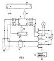
- the conduit 1consists of the inner pipe 2 for transporting a liquid medium and the outer pipe 3.
- the filler 4In the annular space between the two pipes 2, 3 there is the filler 4.
- the probesconsist of a conductor 6 and an insulation 7, one end 8, which is freed from the insulation, being in contact with the filling material 4.
- the ends of the probes 5 facing away from the tube 1are each connected to the measuring device.
- the ends of the filling material 4are each closed with an electrically insulated layer 16 so that there is no unwanted grounding here.
- each conduithas a so-called insulation focus or error focus. This is a point in the line of the pipe at which the focus of the conductivity towards earth has to be considered. In the case of an absolutely fault-free conduit, this center of gravity is 50% of the length, since the leakage resistance Rq is then evenly distributed over the entire length of the pipe.
- R1, R2represent the series resistances of the filling material 4, while R3 represents the error center S.
- Rm1R1 + R3 determined will.
- Rm3R1 + R2 be determined. This results in the three equations shown with three unknowns, from which the values for R1, R2, R3 can be calculated separately.
- the position of the center of gravity Scan be determined from the ratio of R1 to R2 in an appropriate application to the aspect ratio.
- R1 / R2L1 / L2 .
- This measurementapplies regardless of the absolute value of R1, R2, R3.
- An increase in the moisture in the entire annular space between the tubes 2, 3would not falsify the measurement result with regard to the position of the center of gravity S.
- a fault locationwould increase the conductivity at the location of the fault location to earth, thus reducing the resistance R3.
- many methods from cable measurement technologyare possible for the location, in particular the 4-pole measurement via the probes 5.
- a conduit 1is shown in simplified form, to which four probes 5 according to FIG. 1 are connected.
- Each probe 5has a contact resistance U to the filling material 4.
- the measurement results at the left end of the conduit 1are fed to the load cell 20 and from there via the measuring line 11 back to the right start of the conduit 1.
- the switch 12connects the alternating voltage generator 13 with one of the probes at the beginning and at the position shown End of the conduit 1.
- the voltages supplied to the conduit 1 at the beginning and endalso reach the controller R and are compared there. Depending on the comparison, the voltage source 13 is controlled so that the amplitude of the voltages required for the measurement is present in each case.
- F1is a conceivable point of failure that can occur between the conduit 1 and an outer casing, for example concrete pipe 15, or directly to the ground.
- F2denotes a point of failure that can occur between the conduit 1 and a measuring tube 21.
- the changeover switch 12is operated according to a program so that the individual measurements according to FIG. 3 can be carried out one after the other.
- the pipes describedcan be pipes for waste water, pipes for fresh water, for liquid chemicals, water for the transport of district heating or other liquids.
- the described fault location F1can also be between the conduit 1 and an outer casing such as occur in a concrete pipe or directly in the ground.
- the flaws F1 and F2can also be leaky joints in the wall, which encloses the filling material 4 in an electrically insulating manner.
Landscapes
- Physics & Mathematics (AREA)
- General Physics & Mathematics (AREA)
- Examining Or Testing Airtightness (AREA)
Abstract
Description
Translated fromGermanDie Erfindung betrifft eine Einrichtung nach dem Anspruch 10 und ein Verfahren nach dem Anspruch 1.The invention relates to a device according to
Bei aus Sicherheitsgründen doppelwandigen Leitungsrohren mit einem das flüssige Medium führenden Innenrohr und einem das Innenrohr umgebenden Außenrohr besteht in der Praxis die Aufgabe, ein Leck in einer der Wandungen möglichst schnell und einfach festzustellen und außerdem die örtliche Lage des Leckes zu ermitteln. Bei einem derartigen Leck dringt im allgemeinen das flüssige Medium des Innenrohres oder von außen anstehendes Wasser in den Zwischenraum ein. Bisher war es jedoch schwierig, auf einfache Weise einen derartigen Fehler in Form eines Leckes festzustellen und zu orten. Das Problem bestand darin, daß der Luftraum zwischen den Rohren ständig durch Temperaturwechsel (atmen) zur Schwitzwasserbildung neigte und damit an eingebrachten Sensorkabeln üblicher Bauart oft von Anfang an Fehlermeldung verursachte. Bei Sanierung z.B. von Abwasserrohren wird der Raum zwischen den Rohren aus Stabilitätsgründen oft mit Schaumbeton gefüllt, der naturgemäß naß und damit als Lecküberwachung eigentlich ungeeignet ist. Wenn innerhalb eines derartigen Leitungsrohres ein Leck auftritt, wird zwar die Feuchtigkeit des Füllmaterials in dem Zwischenraum an dieser Stelle erhöht. Diese Erhöhung der Feuchtigkeit ist jedoch an den zugänglichen Enden des Leitungsrohren weder optisch noch meßtechnisch kurzfristig feststellbar.For safety reasons, double-walled conduit pipes with an inner pipe carrying the liquid medium and an outer pipe surrounding the inner pipe, in practice the task is to determine a leak in one of the walls as quickly and easily as possible and also to determine the local position of the leak. In the case of such a leak, the liquid medium of the inner tube or water from the outside generally penetrates into the intermediate space. So far, however, it has been difficult to easily identify and locate such a fault in the form of a leak. The problem was that the air space between the tubes constantly tended to form condensation water due to temperature changes (breathing) and thus often caused an error message from the start on sensor cables of conventional design. When renovating sewage pipes, for example, the space between the pipes is often filled with foam concrete for reasons of stability, which is naturally wet and is therefore unsuitable for leak monitoring. If a leak occurs within such a conduit, the moisture of the filling material in the intermediate space is increased at this point. However, this increase in moisture cannot be detected at short notice at the accessible ends of the conduit, neither optically nor by measurement technology.
Bei Neuinstallation wird zur Stabilisierung der Rohre untereinander auch ein Ausdämmen des Zwischenraumes mit Kunststoffschaum praktiziert, wodurch der Zwischenraum zwar trocken bleibt, eine Leckmeldung jedoch stark verzögert wird, wenn der Schaum geschlossene Poren hat, oder aber die Schadensausbreitung begünstigt wird, wenn er offenporig ausgeführt wird.In the case of new installations, insulation of the space between them is also practiced with plastic foam, whereby the space remains dry, but a leakage report is greatly delayed if the foam has closed pores, or the spread of damage is promoted if it is open-pored .
Der Erfindung liegt die Aufgabe zugrunde, ein einfaches universell anwendbares Verfahren zur Fehlerermittlung und Fehlerortung bei einem derartigen Leitungsrohr zu schaffen.The invention has for its object to provide a simple, universally applicable method for fault detection and fault location in such a conduit.
Diese Aufgabe wird durch die im Anspruch 1 angegebene Erfindung gelöst. Im Anspruch 10 ist eine Einrichtung angegeben.This object is achieved by the invention specified in
Die häufig als Sicherheitsmaßnahme vorgesehene Doppelwandigkeit ermöglicht eine schnelle und oft irreversible Ausbreitung einer Flüssigkeit im Schadensfall. Die bisher eine Ortbarkeit behinderte Füllung des Ringraumes wird jetzt mit ihren bisher als nachteilig wirksamen Eigenschaften (Verstopfen des Ringraums, Einschluß der Baufeuchte) genutzt, um zu Schadensbegrenzung, umfassender Überwachung und leichter Ortbarkeit gleichzeitig zu kommen.The double-walled design, which is often provided as a safety measure, enables a liquid to spread quickly and often irreversibly in the event of damage. The filling of the annular space, which was previously difficult to locate, is now used with its previously disadvantageous properties (clogging of the annular space, inclusion of the building moisture) in order to achieve damage limitation, comprehensive monitoring and easy location at the same time.
Bei der erfindungsgemäßen Lösung werden die Isolation des Füllmaterials gegen Erde (innen dargestellt durch das Medium, außen z.B. durch Bodenfeuchte) und der Schwerpunkt in der Leitfähigkeit gegenüber der Erde ohne Vorliegen einer Fehlerquelle als Normalzustand definiert, unabhängig von ihren jeweiligen absoluten Größen. Diese Werte werden dann überwacht. Eine Abweichung von diesem Werten wird als Grundlage für eine Fehlerstelle und für notwendige Reaktionen registriert. Eine Feuchtigkeit in dem Füllmaterial in dem Ringraum, die an sich bisher möglichst vermieden wurde, wird bewußt in Kauf genommen und in vorteilhafter Weise für die Bildung der meßbaren Leitfähigkeit des Füllmaterials ausgenutzt. Die Leitfähigkeit des Füllmaterials kann durch Beimengungen aus elektrisch leitendem Material bewußt erhöht und dadurch kalkulierbar stabilisiert werden. Vorzugsweise wird eine plötzliche Abweichung der gemessenen Werte von den über einen längeren Zeitraum konstanten Werten als Kriterium für das Vorliegen eines Fehlers gewertet. Durch Vergleich der Meßwerte kann darüberhinaus die Lage der Fehlerstelle entlang des Leitungsrohres mit ausreichender Genauigkeit ermittelt werden.In the solution according to the invention, the insulation of the filler material against earth (represented on the inside by the medium, on the outside, for example, by soil moisture) and the center of gravity in the conductivity with respect to the earth are defined as the normal state without a source of error, regardless of their respective absolute sizes. These values are then monitored. A deviation from these values is registered as the basis for an error location and for necessary reactions. A moisture in the filling material in the annular space, which has been avoided as far as possible per se, is becoming known accepted and used in an advantageous manner for the formation of the measurable conductivity of the filling material. The conductivity of the filler material can be deliberately increased by admixtures made of electrically conductive material and thereby stabilized in a calculable manner. A sudden deviation of the measured values from the values that are constant over a longer period of time is preferably evaluated as a criterion for the presence of an error. By comparing the measured values, the position of the fault location along the conduit can also be determined with sufficient accuracy.
Vorzugsweise wird das Meßergebnis jeweils vom Ende des Leitungsrohres über eine Meßleitung zum Anfang des Leitungsrohres übertragen. Am Anfang des Leitungsrohres werden dann die Meßergebnisse vom Anfang und vom Ende des Leitungsrohres der Meß- und Auswertschaltung zugeführt. Diese gibt dann einen Hinweis darauf, ob und an welcher Stelle des Leitungsrohres eine Fehlerstelle vorliegt. Gemäß einer Weiterbildung der Erfindung werden die Meßergebnisse von zwei an sich ähnlichen Leitungsrohr-Strecken verglichen, die ohne Auftreten eines Fehlers bei gleichen Umweltbedingungen etwa gleich sind. Aus einer Abweichung zwischen diesen im Normalfall gleichen oder ähnlichen Meßergebnissen kann auf das Vorliegen einer Fehlerstelle geschlossen werden. Im Regelfall liegt der Fehler in der Leitungsrohr-Strecke, die einen geringeren Isolationswiderstand des Füllmaterials gegen Erde aufweist.The measurement result is preferably transmitted in each case from the end of the conduit via a measuring line to the start of the conduit. At the beginning of the conduit, the measurement results from the beginning and end of the conduit are then fed to the measuring and evaluation circuit. This then gives an indication of whether and at which point in the conduit there is a fault. According to a further development of the invention, the measurement results of two pipe lines which are similar per se are compared and which are approximately the same without an error occurring under the same environmental conditions. From a deviation between these normally identical or similar measurement results, it can be concluded that there is a fault. As a rule, the fault lies in the line pipe section, which has a lower insulation resistance of the filler material to earth.
Die Erfindung wird im folgenden anhand der Zeichnung erläutert. Darin zeigen
- Fig. 1
- im Prinzip ein Leitungsrohr mit einer erfindungsgemäßen Meßeinrichtung,
- Fig. 2, 3
- Ersatzschaltbilder für die elektrischen Eigenschaften des Leitungsrohres und
- Fig. 4
- eine vollständige Meßeinrichtung für ein Leitungsrohr.
- Fig. 1
- in principle a conduit with a measuring device according to the invention,
- 2, 3
- Equivalent circuit diagrams for the electrical properties of the conduit and
- Fig. 4
- a complete measuring device for a conduit.
In Fig. 1 besteht das Leitungsrohr 1 aus dem Innenrohr 2 zum Transport eines flüssigen Mediums sowie dem Außenrohr 3. In dem Ringraum zwischen den beiden Rohren 2, 3 befindet sich das Füllmaterial 4. Jeweils am Anfang und am Ende des Rohres 1 sind vom Stirnende her in das Füllmaterial 4 Sonden 5 eingesteckt, und zwar zwei am Anfang und zwei am Ende an zwei gegeneinander versetzt angeordneten, z.B. diametral gegenüberliegenden Stellen. Die Sonden bestehen aus einem Leiter 6 und einer Isolierung 7, wobei jeweils ein Ende 8, das von der Isolation befreit ist, in Kontakt mit dem Füllmaterial 4 steht. Die von dem Rohr 1 abgewandten Enden der Sonden 5 sind jeweils an die Meßeinrichtung angeschlossen. Die Stirnenden des Füllmaterials 4 sind jeweils mit einer elektrisch isolierten Schicht 16 abgeschlossen damit hier keine unerwünschte Erdung erfolgt.In Fig. 1, the
Fig. 2 zeigt in vereinfachter Darstellung für das Füllmaterial 4 die ohmschen Längswiderstände RL sowie die über die Länge verteilten Querwiderstände Rq, die die Isolation gegen Erde darstellen. Jedes Leitungsrohr hat einen sogenannten Isolationsschwerpunkt oder Fehlerschwerpunkt. Das ist ein Punkt im Verlauf des Leitungsrohres, bei dem der Schwerpunkt der Leitfähigkeit gegenüber Erde zu denken ist. Bei einem absolut fehlerfreien Leitungsrohr liegt dieser Schwerpunkt bei 50 % der Länge, da dann der Ableitwiderstand Rq gleichmäßig über die gesamte Rohrlänge verteilt ist.2 shows a simplified representation of the
Fig. 3 zeigt vereinfacht das elektrische Ersatzschaltbild. R1, R2 stellen die Längswiderstände des Füllmaterials 4 dar, während R3 den Fehlerschwerpunkt S darstellt. Durch Messung des Eingangswiderstandes Rm1 an der Klemme 9 kann bei nicht belasteter Ausgangsklemme 10 der Wert


In Fig. 4 ist vereinfacht ein Leitungsrohr 1 dargestellt, an das vier Sonden 5 gemäß Fig. 1 angeschlossen sind. Jede Sonde 5 hat zum Füllmaterial 4 einen Übergangswiderstand Ü. Die Meßergebnisse am linken Ende des Leitungsrohres 1 werden der Meßdose 20 zugeführt und gelangen von dort über die Meßleitung 11 zurück auf den rechten Anfang des Leitungsrohres 1. Der Umschalter 12 verbindet in der dargestellten Stellung den Wechselspannungsgenerator 13 jeweils mit einer der Sonden am Anfang und am Ende des Leitungsrohres 1. Die dem Leitungsrohr 1 am Anfang und Ende zugeführten Spannungen gelangen außerdem an den Regler R und werden dort verglichen. In Abhängigkeit von dem Vergleich wird die Spannungsquelle 13 so gesteuert, daß jeweils die für die Messung notwendige Amplitude der Spannungen vorliegt. In der gestrichelten Stellung des Umschalters 12 werden die Meßergebnisse vom Anfang und Ende des Leitungsvorganges 1 der Isolationsmeßschaltung 14 zugeführt und dort in der beschriebenen Weise ausgewertet. Mit F1 ist eine denkbare Fehlerstelle bezeichnet, die zwischen dem Leitungsrohr 1 und einer äußeren Umhüllung, z.B. Betonrohr 15, oder direkt dem Erdreich auftreten kann. Mit F2 ist eine Fehlerstelle bezeichnet, die zwischen dem Leitungsrohr 1 und einem Meßrohr 21 auftreten kann. Der Umschalter 12 wird entsprechend einem Programm so betätigt, daß die einzelnen Messungen gemäß Fig. 3 zeitlich nacheinander durchgeführt werden können.4, a
Bei den beschriebenen Rohren kann es sich um Rohre für Abwasser, um Rohre für Frischwasser, für flüssige Chemikalien, Wasser für den Transport von Fernwärme oder sonstige Flüssigkeiten handeln. Die beschriebene Fehlerstelle F1 kann auch zwischen dem Leitungsrohr 1 und einer äußeren Umhüllung wie z.B. einem Betonrohr oder direkt dem Erdreich auftreten. Die Fehlerstellen F1 und F2 können auch undichte Fugen in der Wandung sein, die elektrisch isolierend das Füllmaterial 4 umschließt.The pipes described can be pipes for waste water, pipes for fresh water, for liquid chemicals, water for the transport of district heating or other liquids. The described fault location F1 can also be between the
Claims (11)
- A method of detecting defects in a pipe system which transfers liquid medium, the pipe system including an inner pipe (2) carrying the liquid medium, an outer pipe (3) surrounding the inner pipe (2) and a framework of a filler material (4) in an annular space between both of the said pipes, comprising the steps of:
providing the filler material (4) with a definable electrical conductivity and
detecting the character of a concentration of error (S) by measuring the ohmic resistance of the filler material (4) at the beginning and at the end of a conduit (1) each against an reference voltage level formed by the medium at the inner and by the humidity of ground at the outer, and between the beginning and the end of the conduit (1) and
determining the location of the defect by the methods of measuring cables. - A method as defined in claim 1, wherein said providing step includes:
forming the electrical conductivity by a contemplated wetting of the filler material (4). - A method as defined in claim 1, wherein said providing step includes:
forming or garanting the electrical conductivity by adding electrically conductive material to the filler material (4). - A method as defined in claim 3, wherein said adding step containes:
adding electrically conductive, non-corrosive material to the filler material. - A method as defined in claim 1, further comprising the step of:
transferring the measured result at the end of the conduit (1) by way of a measuring line to the beginning of the conduit (1). - A method as defined in claim 5, wherein said transferring step comprises:
applying an alternating voltage at the beginning and at the end of the conduit (1) and
providing a regulator (R) regulating the amplitude of the alternating voltage to optimized values concerning the measurement. - A method as defined in claim 1, wherein said measuring step includes:
defining the measured values when the conduit having no defects respective normal values and
identifying an abruptly change from the longtime constant values as the appearing of an defect. - A method as defined in claim 1, wherein said measuring step includes:
comparing the measured results of two similar sections of a conduit and
determining the occurence of a defect by detecting a deviation between the measured results. - A method as defined in claim 1, wherein said providing step includes:
terminating the filler material at the beginning and at the end of the conduit with electrically isolating material. - An apparatus for a method of claim 1, comprising: measuring probes (5) formed by a conductor (6) surrounded by insulation (7) being inserted at one end together with the conductor (6) having the insulation (7) removed from the front end of a double-walled conduit to its filler material (4) and being connected to the electrical measuring device (14) at the other end.
- An apparatus as defined in claim 10, further comprising:
measuring probes (5) being inserted in the filler material (4) two for the beginning and two for the end of the conduit each at positions of the transverse section of the conduit being arranged mutually offset from each other.
Priority Applications (4)
| Application Number | Priority Date | Filing Date | Title |
|---|---|---|---|
| EP91112753AEP0533960B1 (en) | 1991-07-29 | 1991-07-29 | Device and procedure for detecting leaks in double walled pipelines for fluids |
| DK91112753.8TDK0533960T3 (en) | 1991-07-29 | 1991-07-29 | Method for Detecting Leakages in Liquid Media Pipes |
| AT91112753TATE112847T1 (en) | 1991-07-29 | 1991-07-29 | EQUIPMENT AND PROCEDURE FOR DETECTING LEAKS IN TUBES FOR LIQUID MEDIA. |
| DE59103240TDE59103240D1 (en) | 1991-07-29 | 1991-07-29 | Device and method for determining leaks on double-walled conduit pipes for liquid media. |
Applications Claiming Priority (1)
| Application Number | Priority Date | Filing Date | Title |
|---|---|---|---|
| EP91112753AEP0533960B1 (en) | 1991-07-29 | 1991-07-29 | Device and procedure for detecting leaks in double walled pipelines for fluids |
Publications (2)
| Publication Number | Publication Date |
|---|---|
| EP0533960A1 EP0533960A1 (en) | 1993-03-31 |
| EP0533960B1true EP0533960B1 (en) | 1994-10-12 |
Family
ID=8206993
Family Applications (1)
| Application Number | Title | Priority Date | Filing Date |
|---|---|---|---|
| EP91112753AExpired - LifetimeEP0533960B1 (en) | 1991-07-29 | 1991-07-29 | Device and procedure for detecting leaks in double walled pipelines for fluids |
Country Status (4)
| Country | Link |
|---|---|
| EP (1) | EP0533960B1 (en) |
| AT (1) | ATE112847T1 (en) |
| DE (1) | DE59103240D1 (en) |
| DK (1) | DK0533960T3 (en) |
Cited By (26)
| Publication number | Priority date | Publication date | Assignee | Title |
|---|---|---|---|---|
| DE102005007988A1 (en)* | 2005-02-22 | 2006-08-24 | Framatome Anp Gmbh | Collection pipe for leakages, e.g. of hydrocarbon compounds, has a perforated carrier pipe with an electrically conductive layer and an outer covering layer |
| US7147655B2 (en) | 2001-03-29 | 2006-12-12 | Xtent, Inc. | Balloon catheter for multiple adjustable stent deployment |
| US7270668B2 (en) | 2001-12-03 | 2007-09-18 | Xtent, Inc. | Apparatus and methods for delivering coiled prostheses |
| US7294146B2 (en) | 2001-12-03 | 2007-11-13 | Xtent, Inc. | Apparatus and methods for delivery of variable length stents |
| US7300456B2 (en) | 2004-06-28 | 2007-11-27 | Xtent, Inc. | Custom-length self-expanding stent delivery systems with stent bumpers |
| US7309350B2 (en) | 2001-12-03 | 2007-12-18 | Xtent, Inc. | Apparatus and methods for deployment of vascular prostheses |
| US7320702B2 (en) | 2005-06-08 | 2008-01-22 | Xtent, Inc. | Apparatus and methods for deployment of multiple custom-length prostheses (III) |
| US7326236B2 (en) | 2003-12-23 | 2008-02-05 | Xtent, Inc. | Devices and methods for controlling and indicating the length of an interventional element |
| US7351255B2 (en) | 2001-12-03 | 2008-04-01 | Xtent, Inc. | Stent delivery apparatus and method |
| US7357812B2 (en) | 2001-12-03 | 2008-04-15 | Xtent, Inc. | Apparatus and methods for delivery of braided prostheses |
| US7402168B2 (en) | 2005-04-11 | 2008-07-22 | Xtent, Inc. | Custom-length stent delivery system with independently operable expansion elements |
| US7553324B2 (en) | 2003-10-14 | 2009-06-30 | Xtent, Inc. | Fixed stent delivery devices and methods |
| US7892273B2 (en) | 2001-12-03 | 2011-02-22 | Xtent, Inc. | Custom length stent apparatus |
| US7905913B2 (en) | 2001-12-03 | 2011-03-15 | Xtent, Inc. | Apparatus and methods for delivery of multiple distributed stents |
| US7918881B2 (en) | 2003-06-09 | 2011-04-05 | Xtent, Inc. | Stent deployment systems and methods |
| US7922755B2 (en) | 2001-12-03 | 2011-04-12 | Xtent, Inc. | Apparatus and methods for delivery of multiple distributed stents |
| US8080048B2 (en) | 2001-12-03 | 2011-12-20 | Xtent, Inc. | Stent delivery for bifurcated vessels |
| US8257427B2 (en) | 2001-09-11 | 2012-09-04 | J.W. Medical Systems, Ltd. | Expandable stent |
| US8282680B2 (en) | 2003-01-17 | 2012-10-09 | J. W. Medical Systems Ltd. | Multiple independent nested stent structures and methods for their preparation and deployment |
| US8317859B2 (en) | 2004-06-28 | 2012-11-27 | J.W. Medical Systems Ltd. | Devices and methods for controlling expandable prostheses during deployment |
| US8460358B2 (en) | 2004-03-30 | 2013-06-11 | J.W. Medical Systems, Ltd. | Rapid exchange interventional devices and methods |
| US8486132B2 (en) | 2007-03-22 | 2013-07-16 | J.W. Medical Systems Ltd. | Devices and methods for controlling expandable prostheses during deployment |
| US8652198B2 (en) | 2006-03-20 | 2014-02-18 | J.W. Medical Systems Ltd. | Apparatus and methods for deployment of linked prosthetic segments |
| US8980297B2 (en) | 2007-02-20 | 2015-03-17 | J.W. Medical Systems Ltd. | Thermo-mechanically controlled implants and methods of use |
| WO2015085696A1 (en)* | 2013-12-10 | 2015-06-18 | 唐山学院 | Control method and apparatus for sulfuric acid leakage monitoring |
| US9101503B2 (en) | 2008-03-06 | 2015-08-11 | J.W. Medical Systems Ltd. | Apparatus having variable strut length and methods of use |
Families Citing this family (15)
| Publication number | Priority date | Publication date | Assignee | Title |
|---|---|---|---|---|
| US5776141A (en)* | 1995-08-28 | 1998-07-07 | Localmed, Inc. | Method and apparatus for intraluminal prosthesis delivery |
| US6077273A (en)* | 1996-08-23 | 2000-06-20 | Scimed Life Systems, Inc. | Catheter support for stent delivery |
| EP1865300A1 (en)* | 2006-06-07 | 2007-12-12 | Basell Poliolefine Italia S.r.l. | Self-diagnostic pipes |
| WO2007141153A1 (en)* | 2006-06-07 | 2007-12-13 | Basell Poliolefine Italia S.R.L. | Self-diagnostic pipes |
| US12076258B2 (en) | 2008-09-25 | 2024-09-03 | Advanced Bifurcation Systems Inc. | Selective stent crimping |
| JP5635515B2 (en) | 2008-09-25 | 2014-12-03 | アドバンスド バイファケーション システムズ, インコーポレイテッド | Partially crimped stent |
| US8821562B2 (en) | 2008-09-25 | 2014-09-02 | Advanced Bifurcation Systems, Inc. | Partially crimped stent |
| US12324756B2 (en) | 2008-09-25 | 2025-06-10 | Advanced Bifurcation Systems Inc. | System and methods for treating a bifurcation |
| US11298252B2 (en) | 2008-09-25 | 2022-04-12 | Advanced Bifurcation Systems Inc. | Stent alignment during treatment of a bifurcation |
| US8828071B2 (en) | 2008-09-25 | 2014-09-09 | Advanced Bifurcation Systems, Inc. | Methods and systems for ostial stenting of a bifurcation |
| CN103037815B (en) | 2010-03-24 | 2015-05-13 | 高级分支系统股份有限公司 | Method and system for treating furcations by temporarily opening side branches |
| AU2011232362B2 (en) | 2010-03-24 | 2015-12-10 | Advanced Bifurcation Systems Inc. | System and methods for treating a bifurcation |
| EP2549951B1 (en) | 2010-03-24 | 2017-05-10 | Advanced Bifurcation Systems, Inc. | Stent alignment during treatment of a bifurcation |
| EP4424283A3 (en) | 2011-02-08 | 2024-12-25 | Advanced Bifurcation Systems Inc. | System and methods for treating a bifurcation with a fully crimped stent |
| WO2012109382A2 (en) | 2011-02-08 | 2012-08-16 | Advanced Bifurcation Systems, Inc. | Multi-stent and multi-balloon apparatus for treating bifurcations and methods of use |
Family Cites Families (1)
| Publication number | Priority date | Publication date | Assignee | Title |
|---|---|---|---|---|
| JPH01148934A (en)* | 1987-12-04 | 1989-06-12 | Junkosha Co Ltd | Leakage detector |
- 1991
- 1991-07-29DEDE59103240Tpatent/DE59103240D1/ennot_activeExpired - Lifetime
- 1991-07-29ATAT91112753Tpatent/ATE112847T1/ennot_activeIP Right Cessation
- 1991-07-29EPEP91112753Apatent/EP0533960B1/ennot_activeExpired - Lifetime
- 1991-07-29DKDK91112753.8Tpatent/DK0533960T3/enactive
Cited By (45)
| Publication number | Priority date | Publication date | Assignee | Title |
|---|---|---|---|---|
| US9980839B2 (en) | 2001-03-29 | 2018-05-29 | J.W. Medical Systems Ltd. | Balloon catheter for multiple adjustable stent deployment |
| US7147655B2 (en) | 2001-03-29 | 2006-12-12 | Xtent, Inc. | Balloon catheter for multiple adjustable stent deployment |
| US9119739B2 (en) | 2001-03-29 | 2015-09-01 | J.W. Medical Systems Ltd. | Balloon catheter for multiple adjustable stent deployment |
| US8257427B2 (en) | 2001-09-11 | 2012-09-04 | J.W. Medical Systems, Ltd. | Expandable stent |
| US8956398B2 (en) | 2001-12-03 | 2015-02-17 | J.W. Medical Systems Ltd. | Custom length stent apparatus |
| US7892274B2 (en) | 2001-12-03 | 2011-02-22 | Xtent, Inc. | Apparatus and methods for deployment of vascular prostheses |
| US9326876B2 (en) | 2001-12-03 | 2016-05-03 | J.W. Medical Systems Ltd. | Apparatus and methods for delivery of multiple distributed stents |
| US7294146B2 (en) | 2001-12-03 | 2007-11-13 | Xtent, Inc. | Apparatus and methods for delivery of variable length stents |
| US7351255B2 (en) | 2001-12-03 | 2008-04-01 | Xtent, Inc. | Stent delivery apparatus and method |
| US7357812B2 (en) | 2001-12-03 | 2008-04-15 | Xtent, Inc. | Apparatus and methods for delivery of braided prostheses |
| US8177831B2 (en) | 2001-12-03 | 2012-05-15 | Xtent, Inc. | Stent delivery apparatus and method |
| US8702781B2 (en) | 2001-12-03 | 2014-04-22 | J.W. Medical Systems Ltd. | Apparatus and methods for delivery of multiple distributed stents |
| US8574282B2 (en) | 2001-12-03 | 2013-11-05 | J.W. Medical Systems Ltd. | Apparatus and methods for delivery of braided prostheses |
| US7309350B2 (en) | 2001-12-03 | 2007-12-18 | Xtent, Inc. | Apparatus and methods for deployment of vascular prostheses |
| US7892273B2 (en) | 2001-12-03 | 2011-02-22 | Xtent, Inc. | Custom length stent apparatus |
| US7905913B2 (en) | 2001-12-03 | 2011-03-15 | Xtent, Inc. | Apparatus and methods for delivery of multiple distributed stents |
| US7270668B2 (en) | 2001-12-03 | 2007-09-18 | Xtent, Inc. | Apparatus and methods for delivering coiled prostheses |
| US7922755B2 (en) | 2001-12-03 | 2011-04-12 | Xtent, Inc. | Apparatus and methods for delivery of multiple distributed stents |
| US7938852B2 (en) | 2001-12-03 | 2011-05-10 | Xtent, Inc. | Apparatus and methods for delivery of braided prostheses |
| US8016870B2 (en) | 2001-12-03 | 2011-09-13 | Xtent, Inc. | Apparatus and methods for delivery of variable length stents |
| US8016871B2 (en) | 2001-12-03 | 2011-09-13 | Xtent, Inc. | Apparatus and methods for delivery of multiple distributed stents |
| US8070789B2 (en) | 2001-12-03 | 2011-12-06 | Xtent, Inc. | Apparatus and methods for deployment of vascular prostheses |
| US8080048B2 (en) | 2001-12-03 | 2011-12-20 | Xtent, Inc. | Stent delivery for bifurcated vessels |
| US8740968B2 (en) | 2003-01-17 | 2014-06-03 | J.W. Medical Systems Ltd. | Multiple independent nested stent structures and methods for their preparation and deployment |
| US8282680B2 (en) | 2003-01-17 | 2012-10-09 | J. W. Medical Systems Ltd. | Multiple independent nested stent structures and methods for their preparation and deployment |
| US7918881B2 (en) | 2003-06-09 | 2011-04-05 | Xtent, Inc. | Stent deployment systems and methods |
| US7553324B2 (en) | 2003-10-14 | 2009-06-30 | Xtent, Inc. | Fixed stent delivery devices and methods |
| US8585747B2 (en) | 2003-12-23 | 2013-11-19 | J.W. Medical Systems Ltd. | Devices and methods for controlling and indicating the length of an interventional element |
| US7326236B2 (en) | 2003-12-23 | 2008-02-05 | Xtent, Inc. | Devices and methods for controlling and indicating the length of an interventional element |
| US8460358B2 (en) | 2004-03-30 | 2013-06-11 | J.W. Medical Systems, Ltd. | Rapid exchange interventional devices and methods |
| US8986362B2 (en) | 2004-06-28 | 2015-03-24 | J.W. Medical Systems Ltd. | Devices and methods for controlling expandable prostheses during deployment |
| US8317859B2 (en) | 2004-06-28 | 2012-11-27 | J.W. Medical Systems Ltd. | Devices and methods for controlling expandable prostheses during deployment |
| US7300456B2 (en) | 2004-06-28 | 2007-11-27 | Xtent, Inc. | Custom-length self-expanding stent delivery systems with stent bumpers |
| US7802465B2 (en) | 2005-02-22 | 2010-09-28 | Areva Np Gmbh | Collecting conduit, apparatus and method for leakage monitoring and leakage location |
| DE102005007988A1 (en)* | 2005-02-22 | 2006-08-24 | Framatome Anp Gmbh | Collection pipe for leakages, e.g. of hydrocarbon compounds, has a perforated carrier pipe with an electrically conductive layer and an outer covering layer |
| US7402168B2 (en) | 2005-04-11 | 2008-07-22 | Xtent, Inc. | Custom-length stent delivery system with independently operable expansion elements |
| US9198784B2 (en) | 2005-06-08 | 2015-12-01 | J.W. Medical Systems Ltd. | Apparatus and methods for deployment of multiple custom-length prostheses |
| US7320702B2 (en) | 2005-06-08 | 2008-01-22 | Xtent, Inc. | Apparatus and methods for deployment of multiple custom-length prostheses (III) |
| US8652198B2 (en) | 2006-03-20 | 2014-02-18 | J.W. Medical Systems Ltd. | Apparatus and methods for deployment of linked prosthetic segments |
| US8980297B2 (en) | 2007-02-20 | 2015-03-17 | J.W. Medical Systems Ltd. | Thermo-mechanically controlled implants and methods of use |
| US9457133B2 (en) | 2007-02-20 | 2016-10-04 | J.W. Medical Systems Ltd. | Thermo-mechanically controlled implants and methods of use |
| US9339404B2 (en) | 2007-03-22 | 2016-05-17 | J.W. Medical Systems Ltd. | Devices and methods for controlling expandable prostheses during deployment |
| US8486132B2 (en) | 2007-03-22 | 2013-07-16 | J.W. Medical Systems Ltd. | Devices and methods for controlling expandable prostheses during deployment |
| US9101503B2 (en) | 2008-03-06 | 2015-08-11 | J.W. Medical Systems Ltd. | Apparatus having variable strut length and methods of use |
| WO2015085696A1 (en)* | 2013-12-10 | 2015-06-18 | 唐山学院 | Control method and apparatus for sulfuric acid leakage monitoring |
Also Published As
| Publication number | Publication date |
|---|---|
| EP0533960A1 (en) | 1993-03-31 |
| DE59103240D1 (en) | 1994-11-17 |
| DK0533960T3 (en) | 1995-01-30 |
| ATE112847T1 (en) | 1994-10-15 |
Similar Documents
| Publication | Publication Date | Title |
|---|---|---|
| EP0533960B1 (en) | Device and procedure for detecting leaks in double walled pipelines for fluids | |
| DE4015075C2 (en) | Procedure for the determination of leaks in line pipes for liquid media | |
| DE2431907C3 (en) | Method and device for determining concentration profiles of liquid or gaseous substances along a route | |
| AT501758B1 (en) | METHOD OF LOCATING LEAKAGE IN TUBE | |
| DE2413345C2 (en) | Insulated pipeline system, especially an underground pipeline system for district heating | |
| EP0990894A2 (en) | Method for determining the electrical conductivity of liquids | |
| DE3930530C2 (en) | ||
| DE69014002T2 (en) | Process for the continuous control of the functionality of underground metallic structures and devices for its implementation. | |
| DE3327762A1 (en) | METHOD AND DEVICE FOR INSPECTING FERROMAGNETIC ELEMENTS | |
| DE102012017415A1 (en) | Method for monitoring efficacy of cathodic corrosion protection of system i.e. pipeline made from steel, involves determining changes of protection current directly or indirectly by measuring changes of pH-values of soil enclosing probe | |
| WO2020001933A1 (en) | Sensor device and method for determining an alternating voltage | |
| DE19519650C2 (en) | Process for locating leaks in pipelines and piping systems, in particular for the transmission of district heating | |
| DE3225742A1 (en) | Circuit arrangement for determining leakage points in insulated pipelines | |
| DE19521018C2 (en) | Pipe system, in particular for the transmission of district heating | |
| DE2322085A1 (en) | FLUID-FILLED ELECTRIC CABLE | |
| DE3424308A1 (en) | DEVICE FOR LOCATING A DEFECTIVE AREA OF A METAL PIPE | |
| DE3503391A1 (en) | Method for the structural inspection and operation inspection of remote-heating lines, and a device | |
| DE1814857A1 (en) | Arrangement for signaling leaks in a pipeline for the transport of liquids | |
| DE3237895A1 (en) | CABLE ERROR LOCATION METHOD FOR INTERRUPTIONS WITH HUMIDITY COMPENSATION | |
| DE3232211C2 (en) | Medium transport line | |
| DE10024478A1 (en) | Process for determining a leak in a pipe comprises applying a first insulating layer, a conducting layer and a second insulating layer on the inner wall of a pipe, and measuring the resistance | |
| DE19610475C1 (en) | Device for locating leaks in pipes and in pipe connections esp. sewage, drain and waste water pipes | |
| EP3449244B1 (en) | Arrangement and method for detecting damage to an inner coating of a container | |
| EP1605247A1 (en) | Measurement probe for determining the depth of corrosion attack, process for measuring the depth of corrosion attack, and use of a measurement probe | |
| DE3125388A1 (en) | "METHOD AND DEVICE FOR CONTINUOUS MONITORING OF SYSTEMS CONTAINING FLUID MEDIA" |
Legal Events
| Date | Code | Title | Description |
|---|---|---|---|
| PUAI | Public reference made under article 153(3) epc to a published international application that has entered the european phase | Free format text:ORIGINAL CODE: 0009012 | |
| 17P | Request for examination filed | Effective date:19920511 | |
| AK | Designated contracting states | Kind code of ref document:A1 Designated state(s):AT BE CH DE DK ES FR GB GR IT LI LU NL SE | |
| 17Q | First examination report despatched | Effective date:19930714 | |
| GRAA | (expected) grant | Free format text:ORIGINAL CODE: 0009210 | |
| AK | Designated contracting states | Kind code of ref document:B1 Designated state(s):AT BE CH DE DK ES FR GB GR IT LI LU NL SE | |
| PG25 | Lapsed in a contracting state [announced via postgrant information from national office to epo] | Ref country code:FR Effective date:19941012 Ref country code:IT Free format text:LAPSE BECAUSE OF FAILURE TO SUBMIT A TRANSLATION OF THE DESCRIPTION OR TO PAY THE FEE WITHIN THE PRESCRIBED TIME-LIMIT;WARNING: LAPSES OF ITALIAN PATENTS WITH EFFECTIVE DATE BEFORE 2007 MAY HAVE OCCURRED AT ANY TIME BEFORE 2007. THE CORRECT EFFECTIVE DATE MAY BE DIFFERENT FROM THE ONE RECORDED. Effective date:19941012 Ref country code:GR Free format text:LAPSE BECAUSE OF FAILURE TO SUBMIT A TRANSLATION OF THE DESCRIPTION OR TO PAY THE FEE WITHIN THE PRESCRIBED TIME-LIMIT Effective date:19941012 Ref country code:GB Effective date:19941012 Ref country code:ES Free format text:THE PATENT HAS BEEN ANNULLED BY A DECISION OF A NATIONAL AUTHORITY Effective date:19941012 Ref country code:BE Effective date:19941012 Ref country code:NL Effective date:19941012 | |
| REF | Corresponds to: | Ref document number:112847 Country of ref document:AT Date of ref document:19941015 Kind code of ref document:T | |
| RBV | Designated contracting states (corrected) | Designated state(s):AT BE CH DK ES FR GB GR IT LI LU NL SE | |
| REF | Corresponds to: | Ref document number:59103240 Country of ref document:DE Date of ref document:19941117 | |
| PG25 | Lapsed in a contracting state [announced via postgrant information from national office to epo] | Ref country code:SE Effective date:19950112 | |
| REG | Reference to a national code | Ref country code:DK Ref legal event code:T3 | |
| EN | Fr: translation not filed | ||
| NLV1 | Nl: lapsed or annulled due to failure to fulfill the requirements of art. 29p and 29m of the patents act | ||
| GBV | Gb: ep patent (uk) treated as always having been void in accordance with gb section 77(7)/1977 [no translation filed] | Effective date:19941012 | |
| PG25 | Lapsed in a contracting state [announced via postgrant information from national office to epo] | Ref country code:AT Effective date:19950729 | |
| PG25 | Lapsed in a contracting state [announced via postgrant information from national office to epo] | Ref country code:LU Free format text:LAPSE BECAUSE OF NON-PAYMENT OF DUE FEES Effective date:19950731 | |
| PLBE | No opposition filed within time limit | Free format text:ORIGINAL CODE: 0009261 | |
| STAA | Information on the status of an ep patent application or granted ep patent | Free format text:STATUS: NO OPPOSITION FILED WITHIN TIME LIMIT | |
| 26N | No opposition filed | ||
| PGFP | Annual fee paid to national office [announced via postgrant information from national office to epo] | Ref country code:DK Payment date:19960716 Year of fee payment:6 | |
| PGFP | Annual fee paid to national office [announced via postgrant information from national office to epo] | Ref country code:CH Payment date:19960729 Year of fee payment:6 | |
| PG25 | Lapsed in a contracting state [announced via postgrant information from national office to epo] | Ref country code:DK Free format text:LAPSE BECAUSE OF NON-PAYMENT OF DUE FEES Effective date:19970729 | |
| REG | Reference to a national code | Ref country code:DK Ref legal event code:EBP | |
| PG25 | Lapsed in a contracting state [announced via postgrant information from national office to epo] | Ref country code:LI Free format text:LAPSE BECAUSE OF NON-PAYMENT OF DUE FEES Effective date:19970731 Ref country code:CH Free format text:LAPSE BECAUSE OF NON-PAYMENT OF DUE FEES Effective date:19970731 | |
| REG | Reference to a national code | Ref country code:CH Ref legal event code:PL |