EP0533360B1 - Electrosurgery apparatus - Google Patents
Electrosurgery apparatusDownload PDFInfo
- Publication number
- EP0533360B1 EP0533360B1EP92307744AEP92307744AEP0533360B1EP 0533360 B1EP0533360 B1EP 0533360B1EP 92307744 AEP92307744 AEP 92307744AEP 92307744 AEP92307744 AEP 92307744AEP 0533360 B1EP0533360 B1EP 0533360B1
- Authority
- EP
- European Patent Office
- Prior art keywords
- earth
- circuit
- electrode
- input
- alarm
- Prior art date
- Legal status (The legal status is an assumption and is not a legal conclusion. Google has not performed a legal analysis and makes no representation as to the accuracy of the status listed.)
- Expired - Lifetime
Links
- 239000003990capacitorSubstances0.000description6
- 230000015271coagulationEffects0.000description1
- 238000005345coagulationMethods0.000description1
- 238000012544monitoring processMethods0.000description1
- 238000001356surgical procedureMethods0.000description1
Images
Classifications
- A—HUMAN NECESSITIES
- A61—MEDICAL OR VETERINARY SCIENCE; HYGIENE
- A61B—DIAGNOSIS; SURGERY; IDENTIFICATION
- A61B18/00—Surgical instruments, devices or methods for transferring non-mechanical forms of energy to or from the body
- A61B18/04—Surgical instruments, devices or methods for transferring non-mechanical forms of energy to or from the body by heating
- A61B18/12—Surgical instruments, devices or methods for transferring non-mechanical forms of energy to or from the body by heating by passing a current through the tissue to be heated, e.g. high-frequency current
- A61B18/14—Probes or electrodes therefor
- A61B18/16—Indifferent or passive electrodes for grounding
- Y—GENERAL TAGGING OF NEW TECHNOLOGICAL DEVELOPMENTS; GENERAL TAGGING OF CROSS-SECTIONAL TECHNOLOGIES SPANNING OVER SEVERAL SECTIONS OF THE IPC; TECHNICAL SUBJECTS COVERED BY FORMER USPC CROSS-REFERENCE ART COLLECTIONS [XRACs] AND DIGESTS
- Y10—TECHNICAL SUBJECTS COVERED BY FORMER USPC
- Y10S—TECHNICAL SUBJECTS COVERED BY FORMER USPC CROSS-REFERENCE ART COLLECTIONS [XRACs] AND DIGESTS
- Y10S128/00—Surgery
- Y10S128/908—Patient protection from electric shock
Definitions
- This inventionrelates to electrosurgery equipment of the kind including an r.f. power supply arranged to supply power to an active electrode and having a return path via a large area plate electrode.
- Electrosurgery equipmentis used to perform cutting or coagulation operations during surgery. Radio frequency current is supplied to an active, hand-held electrode that the surgeon manipulates in order to perform the operation. Current is returned to the electrosurgery generator via a large area plate which is attached to a part of the patient's body. The large area of the return plate ensures that there is a low current density in this region, so that the patient's tissue is not damaged.
- electrosurgery equipmentof the above-specified kind, characterized in that the equipment includes an alarm circuit having two inputs, that one input is connected between the active electrode and ground, that the second input is connected between the plate electrode and ground, that the alarm circuit includes a circuit for measuring the difference between the voltage on the active electrode with respect to earth and the plate electrode with respect to earth, and that the circuit provides an alarm signal when the voltage on the plate electrode rises relative to the active electrode by more than a predetermined amount with respect to earth.
- the alarm signalmay inhibit the output from the power supply.
- the circuitmay include a first capacitive divider connected between the active electrode and earth and a second capacitive divider connected between the plate electrode and earth.
- the circuitmay include a diffential amplifier having one input connected with the first capacitive divider and another input connected with the second capactive divider.
- the circuitmay include a comparator that receives at one input the output of the differential amplifier and at another input a reference signal, the comparator providing the alarm signal when the otuput of the differential amplifier rises above the reference signal.
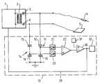
- the electrosurgery equipmentincludes a conventional r.f. power supply 1 which provides an r.f. output via a transformer 2 and a capacitor 3 to an active, hand-held electrode 4. Return current from the patient is supplied via a large area flexible plate electrode 5 which is secured firmly to a part of the patient. The return current is supplied back to the transformer 2 via a second capacitor 6.
- the equipmentalso includes an alarm circuit 10 which monitors correct attachment of the return plate 5 to the patient.
- the alarm circuit 10includes a first capacitive divider 11 comprising a series connection of two capacitors 12 and 13 connected at one end to the supply line to the active electrode 4 and at the other end to earth.
- a second capacitive divider 14comprising a series connection of two capacitors 15 and 16 is connected at one end to the return line from the plate 5 and at the other end to earth.
- the a.c. voltage at a point between the two capacitors 12 and 13 in the first divider 11is rectified by a rectifier circuit 21 to produce a d.c. voltage which is applied to one input of a differential amplifier 22.
- the differential amplifier 22amplifies the difference between the two d.c. voltages.
- the output of the differential amplifier 22is connected to one input of a comparator 30 which receives a reference voltage at its other input from a voltage source 31.
- the output from the comparator 30is connected to an audible alarm 32 and to the power supply 1 via line 33.
- the patient's bodyWhen the plate 5 is properly attached to the patient, the patient's body provides a capacitance between the plate and earth of the order of hundreds of picofarads. This causes the a.c. voltage between the plate 5 and earth to remain low.
- the a.c. voltage on the plate with respect to earthwill rise relative to the voltage on the active electrode.
- the rectifier circuits 21 and 23 and the gain of the differential amplifier 22are arranged such that, when the plate 5 is properly attached to the patient and the active electrode 4 is not earthed, the output from the differential amplifier is below the reference voltage. When, however, the plate 5 becomes detached, or the active electrode 4 becomes earthed, the output from the differential amplifier 22 rises above the reference level and causes the comparator 30 to generate an alarm signal.
- the alarm signalis supplied both to the audible alarm 32, to provide a sound that alerts the surgeon, and to the power supply 1 to disable the output and terminate the supply of current to the patient, thereby reducing the risk of burns to the patient.
- the equipmentneed not employ capacitive dividers but could have alternative means for measuring the difference between the voltages on the active electrode and plate electrode.
- present inventionenables an alarm signal to be produced without the need to use special electrodes.
Landscapes
- Health & Medical Sciences (AREA)
- Surgery (AREA)
- Engineering & Computer Science (AREA)
- Life Sciences & Earth Sciences (AREA)
- Medical Informatics (AREA)
- General Health & Medical Sciences (AREA)
- Nuclear Medicine, Radiotherapy & Molecular Imaging (AREA)
- Plasma & Fusion (AREA)
- Biomedical Technology (AREA)
- Heart & Thoracic Surgery (AREA)
- Physics & Mathematics (AREA)
- Molecular Biology (AREA)
- Animal Behavior & Ethology (AREA)
- Otolaryngology (AREA)
- Public Health (AREA)
- Veterinary Medicine (AREA)
- Surgical Instruments (AREA)
- Measuring And Recording Apparatus For Diagnosis (AREA)
- Infusion, Injection, And Reservoir Apparatuses (AREA)
- Measurement And Recording Of Electrical Phenomena And Electrical Characteristics Of The Living Body (AREA)
- Measurement Of Current Or Voltage (AREA)
- Measurement Of Resistance Or Impedance (AREA)
Description
- This invention relates to electrosurgery equipment of the kind including an r.f. power supply arranged to supply power to an active electrode and having a return path via a large area plate electrode.
- Electrosurgery equipment is used to perform cutting or coagulation operations during surgery. Radio frequency current is supplied to an active, hand-held electrode that the surgeon manipulates in order to perform the operation. Current is returned to the electrosurgery generator via a large area plate which is attached to a part of the patient's body. The large area of the return plate ensures that there is a low current density in this region, so that the patient's tissue is not damaged.
- One of the problems with electrosurgery equipment of this kind is that the return electrode may separate from the patient so that the contact area is reduced. This can lead to burning of the tissue in the regions where the plate and patient tissue contact. One way of overcoming this problem is to use a return plate electrode that is divided into two parts which are isolated electrically from one another. When the plate is in good contact with the patient's tissue, there will be a low resistance between the two parts of the electrode. By monitoring the resistance between the two parts of the electrode it is possible to detect when the electrode becomes separated from the patient and to cause an alarm or disconnection of the power supply. The problem with this arrangement, however, is that it is necessary to use a special plate electrode. US-A-3923063 describes a circuit for detecting when one of the patient electrodes is not in contact with the patient and for reducing output power in response to this.
- It is an object of the present invention to provide improved equipment that does not require a special plate electrode.
- According to one aspect of the present invention there is provided electrosurgery equipment of the above-specified kind, characterized in that the equipment includes an alarm circuit having two inputs, that one input is connected between the active electrode and ground, that the second input is connected between the plate electrode and ground, that the alarm circuit includes a circuit for measuring the difference between the voltage on the active electrode with respect to earth and the plate electrode with respect to earth, and that the circuit provides an alarm signal when the voltage on the plate electrode rises relative to the active electrode by more than a predetermined amount with respect to earth.
- The alarm signal may inhibit the output from the power supply. The circuit may include a first capacitive divider connected between the active electrode and earth and a second capacitive divider connected between the plate electrode and earth. The circuit may include a diffential amplifier having one input connected with the first capacitive divider and another input connected with the second capactive divider. The circuit may include a comparator that receives at one input the output of the differential amplifier and at another input a reference signal, the comparator providing the alarm signal when the otuput of the differential amplifier rises above the reference signal.
- Electrosurgery equipment in accordance with the present invention will now be described, by way of example, with reference to the accompanying drawing which shows the equipment schematically.
- The electrosurgery equipment includes a conventional r.f.
power supply 1 which provides an r.f. output via atransformer 2 and a capacitor 3 to an active, hand-held electrode 4. Return current from the patient is supplied via a large areaflexible plate electrode 5 which is secured firmly to a part of the patient. The return current is supplied back to thetransformer 2 via asecond capacitor 6. - The equipment also includes an
alarm circuit 10 which monitors correct attachment of thereturn plate 5 to the patient. Thealarm circuit 10 includes a firstcapacitive divider 11 comprising a series connection of twocapacitors capacitive divider 14 comprising a series connection of twocapacitors plate 5 and at the other end to earth. The a.c. voltage at a point between the twocapacitors first divider 11 is rectified by arectifier circuit 21 to produce a d.c. voltage which is applied to one input of adifferential amplifier 22. Similarly, the a.c. voltage at a point between thecapacitors second divider 14 is rectified by arectifier circuit 23 to produce a d.c. voltage which is applied to the other input of thedifferential amplifier 22. Thedifferential amplifier 22 amplifies the difference between the two d.c. voltages. The output of thedifferential amplifier 22 is connected to one input of acomparator 30 which receives a reference voltage at its other input from avoltage source 31. The output from thecomparator 30 is connected to anaudible alarm 32 and to thepower supply 1 vialine 33. - When the
plate 5 is properly attached to the patient, the patient's body provides a capacitance between the plate and earth of the order of hundreds of picofarads. This causes the a.c. voltage between theplate 5 and earth to remain low. - If the
plate 5 becomes detached, or the active electrode 4 is earthed, the a.c. voltage on the plate with respect to earth will rise relative to the voltage on the active electrode. - The
rectifier circuits differential amplifier 22 are arranged such that, when theplate 5 is properly attached to the patient and the active electrode 4 is not earthed, the output from the differential amplifier is below the reference voltage. When, however, theplate 5 becomes detached, or the active electrode 4 becomes earthed, the output from thedifferential amplifier 22 rises above the reference level and causes thecomparator 30 to generate an alarm signal. The alarm signal is supplied both to theaudible alarm 32, to provide a sound that alerts the surgeon, and to thepower supply 1 to disable the output and terminate the supply of current to the patient, thereby reducing the risk of burns to the patient. - It will be appreciated that the equipment need not employ capacitive dividers but could have alternative means for measuring the difference between the voltages on the active electrode and plate electrode.
- It can be seen that present invention enables an alarm signal to be produced without the need to use special electrodes.
Claims (5)
- Electrosurgery equipment including an r.f. power supply (1) arranged to supply power to an active electrode (4) and having a return path via a large area plate electrode (5), characterised in that the equipment includes an alarm circuit (10) having two inputs, that one input is connected between the active electrode (4) and earth, that the second input is connected between the plate electrode (5) and earth, that the alarm circuit (10) includes a circuit (21-23) for measuring the difference between the voltage on the active electrode (4) with respect to earth and the plate electrode (5) with respect to earth, and that the circuit provides an alarm signal when the voltage on the plate electrode rises relative to the active electrode by more than a predetermined amount with respect to earth.
- Electrosurgery equipment according to Claim 1, characterised in that the alarm inhibits the output from the power supply (1).
- Electrosurgery equipment according to Claim 1 or 2, characterised in that the circuit (10) includes a first capacitive divider (11) connected between the active electrode (4) and earth and a second capacitive divider (14) connected between the plate electrode (5) and earth.
- Electrosurgery equipment according to Claim 3, characterised in that the circuit (10) includes a differential amplifier (22) having one input connected with the first capacitive divider (11) and another input connected with the second capacitive divider (14).
- Electrosurgery equipment according to Claim 4, characterised in that the circuit includes a comparator (30) that receives at one input the output of the differential amplifier (22) and at another input a reference signal, and that the comparator (30) provides the alarm signal when the output of the differential amplifier (22) rises above the reference signal.
Applications Claiming Priority (2)
| Application Number | Priority Date | Filing Date | Title |
|---|---|---|---|
| GB919119695AGB9119695D0 (en) | 1991-09-14 | 1991-09-14 | Electrosurgery equipment |
| GB9119695 | 1991-09-14 |
Publications (2)
| Publication Number | Publication Date |
|---|---|
| EP0533360A1 EP0533360A1 (en) | 1993-03-24 |
| EP0533360B1true EP0533360B1 (en) | 1996-10-09 |
Family
ID=10701440
Family Applications (1)
| Application Number | Title | Priority Date | Filing Date |
|---|---|---|---|
| EP92307744AExpired - LifetimeEP0533360B1 (en) | 1991-09-14 | 1992-08-25 | Electrosurgery apparatus |
Country Status (7)
| Country | Link |
|---|---|
| US (1) | US5246439A (en) |
| EP (1) | EP0533360B1 (en) |
| JP (1) | JPH05192347A (en) |
| DE (1) | DE69214394T2 (en) |
| ES (1) | ES2092648T3 (en) |
| GB (2) | GB9119695D0 (en) |
| ZA (1) | ZA926715B (en) |
Families Citing this family (25)
| Publication number | Priority date | Publication date | Assignee | Title |
|---|---|---|---|---|
| US5436566A (en)* | 1992-03-17 | 1995-07-25 | Conmed Corporation | Leakage capacitance compensating current sensor for current supplied to medical device loads |
| US5432459A (en)* | 1992-03-17 | 1995-07-11 | Conmed Corporation | Leakage capacitance compensating current sensor for current supplied to medical device loads with unconnected reference conductor |
| EP0631144A1 (en)* | 1993-06-24 | 1994-12-28 | Koninklijke Philips Electronics N.V. | High voltage differential sensor having a capacitive attenuator |
| US5907251A (en)* | 1996-11-22 | 1999-05-25 | International Business Machines Corp. | Low voltage swing capacitive bus driver device |
| US5807253A (en)* | 1997-10-06 | 1998-09-15 | General Electrical Company | Patient electrical isolation system |
| AU2002303942B2 (en) | 2001-06-01 | 2006-06-22 | Covidien Ag | Return pad cable connector |
| US6860881B2 (en) | 2002-09-25 | 2005-03-01 | Sherwood Services Ag | Multiple RF return pad contact detection system |
| CA2542849C (en) | 2003-10-23 | 2013-08-20 | Sherwood Services Ag | Redundant temperature monitoring in electrosurgical systems for safety mitigation |
| CA2541037A1 (en) | 2005-03-31 | 2006-09-30 | Sherwood Services Ag | Temperature regulating patient return electrode and return electrode monitoring system |
| US7736359B2 (en) | 2006-01-12 | 2010-06-15 | Covidien Ag | RF return pad current detection system |
| US7637907B2 (en)* | 2006-09-19 | 2009-12-29 | Covidien Ag | System and method for return electrode monitoring |
| US7722603B2 (en) | 2006-09-28 | 2010-05-25 | Covidien Ag | Smart return electrode pad |
| US7927329B2 (en) | 2006-09-28 | 2011-04-19 | Covidien Ag | Temperature sensing return electrode pad |
| US8777940B2 (en) | 2007-04-03 | 2014-07-15 | Covidien Lp | System and method for providing even heat distribution and cooling return pads |
| US8021360B2 (en) | 2007-04-03 | 2011-09-20 | Tyco Healthcare Group Lp | System and method for providing even heat distribution and cooling return pads |
| US8080007B2 (en) | 2007-05-07 | 2011-12-20 | Tyco Healthcare Group Lp | Capacitive electrosurgical return pad with contact quality monitoring |
| US8388612B2 (en) | 2007-05-11 | 2013-03-05 | Covidien Lp | Temperature monitoring return electrode |
| US8231614B2 (en) | 2007-05-11 | 2012-07-31 | Tyco Healthcare Group Lp | Temperature monitoring return electrode |
| US8100898B2 (en) | 2007-08-01 | 2012-01-24 | Tyco Healthcare Group Lp | System and method for return electrode monitoring |
| US8801703B2 (en) | 2007-08-01 | 2014-08-12 | Covidien Lp | System and method for return electrode monitoring |
| US8523853B2 (en)* | 2008-02-05 | 2013-09-03 | Covidien Lp | Hybrid contact quality monitoring return electrode |
| US9578728B2 (en)* | 2013-06-18 | 2017-02-21 | Dialight Corporation | Long life, fail safe traffic light |
| US20190083162A1 (en) | 2017-09-19 | 2019-03-21 | Biosense Webster (Israel) Ltd. | Electrode disconnect detection |
| US11364076B2 (en) | 2019-12-12 | 2022-06-21 | Covidien Lp | Monopolar return pad |
| DE102021132367A1 (en) | 2021-12-07 | 2023-06-07 | Olympus Winter & Ibe Gmbh | Electrosurgical generator with leakage current detection |
Family Cites Families (11)
| Publication number | Priority date | Publication date | Assignee | Title |
|---|---|---|---|---|
| GB855459A (en)* | 1958-04-11 | 1960-11-30 | Keeler Optical Products Ltd | Improvements in or relating to electro-surgical apparatus |
| JPS5241593B2 (en)* | 1972-12-29 | 1977-10-19 | ||
| GB1480736A (en)* | 1973-08-23 | 1977-07-20 | Matburn Ltd | Electrodiathermy apparatus |
| US3923063A (en)* | 1974-07-15 | 1975-12-02 | Sybron Corp | Pulse control circuit for electrosurgical units |
| US4231372A (en)* | 1974-11-04 | 1980-11-04 | Valleylab, Inc. | Safety monitoring circuit for electrosurgical unit |
| US4094320A (en)* | 1976-09-09 | 1978-06-13 | Valleylab, Inc. | Electrosurgical safety circuit and method of using same |
| FR2391588A1 (en)* | 1977-05-18 | 1978-12-15 | Satelec Soc | HIGH FREQUENCY VOLTAGE GENERATOR |
| GB8324442D0 (en)* | 1983-09-13 | 1983-10-12 | Matburn Holdings Ltd | Electrosurgical system |
| DE3516354A1 (en)* | 1985-05-07 | 1986-11-13 | Werner Prof. Dr.-Ing. 6301 Wettenberg Irnich | MONITORING DEVICE FOR A HIGH-FREQUENCY SURGERY DEVICE |
| US4662369A (en)* | 1986-04-04 | 1987-05-05 | Castle Company | Electrosurgical apparatus having a safety circuit |
| US4848335B1 (en)* | 1988-02-16 | 1994-06-07 | Aspen Lab Inc | Return electrode contact monitor |
- 1991
- 1991-09-14GBGB919119695Apatent/GB9119695D0/enactivePending
- 1992
- 1992-08-25ESES92307744Tpatent/ES2092648T3/ennot_activeExpired - Lifetime
- 1992-08-25DEDE69214394Tpatent/DE69214394T2/ennot_activeExpired - Fee Related
- 1992-08-25EPEP92307744Apatent/EP0533360B1/ennot_activeExpired - Lifetime
- 1992-09-01USUS07/937,717patent/US5246439A/ennot_activeExpired - Fee Related
- 1992-09-01GBGB9218496Apatent/GB2259453B/ennot_activeExpired - Fee Related
- 1992-09-02JPJP4234651Apatent/JPH05192347A/enactivePending
- 1992-09-04ZAZA926715Apatent/ZA926715B/enunknown
Also Published As
| Publication number | Publication date |
|---|---|
| ZA926715B (en) | 1993-03-09 |
| GB2259453A (en) | 1993-03-17 |
| GB9218496D0 (en) | 1992-10-14 |
| GB9119695D0 (en) | 1991-10-30 |
| GB2259453B (en) | 1995-07-12 |
| DE69214394D1 (en) | 1996-11-14 |
| US5246439A (en) | 1993-09-21 |
| ES2092648T3 (en) | 1996-12-01 |
| JPH05192347A (en) | 1993-08-03 |
| EP0533360A1 (en) | 1993-03-24 |
| DE69214394T2 (en) | 1997-02-20 |
Similar Documents
| Publication | Publication Date | Title |
|---|---|---|
| EP0533360B1 (en) | Electrosurgery apparatus | |
| US7938825B2 (en) | Multiple RF return pad contact detection system | |
| US4662369A (en) | Electrosurgical apparatus having a safety circuit | |
| US6063075A (en) | Electrosurgical apparatus and separation detecting method capable of stably monitoring separation state of return electrode | |
| US10182860B2 (en) | Assessment of electrode coupling for tissue ablation | |
| US3913583A (en) | Control circuit for electrosurgical units | |
| US5496313A (en) | System for detecting penetration of medical instruments | |
| EP0544415B1 (en) | Patient support tables and monitors | |
| US8998890B2 (en) | Assessment of electrode coupling for tissue ablation | |
| US8267926B2 (en) | Assessment of electrode coupling for tissue ablation | |
| US4126137A (en) | Electrosurgical unit | |
| US4188927A (en) | Multiple source electrosurgical generator | |
| EP3720372B1 (en) | System for controlling patient leakage current in a surgical system | |
| US20100298823A1 (en) | Assessment of electrode coupling for tissue ablation | |
| EP0171967A2 (en) | Electrosurgical generator | |
| DE59009806D1 (en) | High frequency electrosurgical unit. | |
| GB2276551A (en) | Electrosurgery monitor and apparatus | |
| GB2374532A (en) | Electrosurgery apparatus monitoring impedance of split-plate return electrode | |
| US4796630A (en) | Cardiac pacemaker with combined defibrillation and electrosurgery protection | |
| US20220133391A1 (en) | Electrosurgical generator with inverter for generating hf high voltage | |
| CN116269726A (en) | Electrosurgical generator with leakage current detection |
Legal Events
| Date | Code | Title | Description |
|---|---|---|---|
| PUAI | Public reference made under article 153(3) epc to a published international application that has entered the european phase | Free format text:ORIGINAL CODE: 0009012 | |
| 17P | Request for examination filed | Effective date:19921203 | |
| AK | Designated contracting states | Kind code of ref document:A1 Designated state(s):DE ES IE IT | |
| 17Q | First examination report despatched | Effective date:19950428 | |
| GRAG | Despatch of communication of intention to grant | Free format text:ORIGINAL CODE: EPIDOS AGRA | |
| GRAH | Despatch of communication of intention to grant a patent | Free format text:ORIGINAL CODE: EPIDOS IGRA | |
| GRAH | Despatch of communication of intention to grant a patent | Free format text:ORIGINAL CODE: EPIDOS IGRA | |
| GRAA | (expected) grant | Free format text:ORIGINAL CODE: 0009210 | |
| AK | Designated contracting states | Kind code of ref document:B1 Designated state(s):DE ES IE IT | |
| REF | Corresponds to: | Ref document number:69214394 Country of ref document:DE Date of ref document:19961114 | |
| REG | Reference to a national code | Ref country code:ES Ref legal event code:FG2A Ref document number:2092648 Country of ref document:ES Kind code of ref document:T3 | |
| REG | Reference to a national code | Ref country code:IE Ref legal event code:FG4D Free format text:70213 | |
| ITF | It: translation for a ep patent filed | ||
| PLBE | No opposition filed within time limit | Free format text:ORIGINAL CODE: 0009261 | |
| STAA | Information on the status of an ep patent application or granted ep patent | Free format text:STATUS: NO OPPOSITION FILED WITHIN TIME LIMIT | |
| PG25 | Lapsed in a contracting state [announced via postgrant information from national office to epo] | Ref country code:IE Free format text:LAPSE BECAUSE OF NON-PAYMENT OF DUE FEES Effective date:19970825 | |
| PG25 | Lapsed in a contracting state [announced via postgrant information from national office to epo] | Ref country code:ES Free format text:LAPSE BECAUSE OF THE APPLICANT RENOUNCES Effective date:19970826 | |
| 26N | No opposition filed | ||
| PG25 | Lapsed in a contracting state [announced via postgrant information from national office to epo] | Ref country code:DE Free format text:LAPSE BECAUSE OF NON-PAYMENT OF DUE FEES Effective date:19980501 | |
| REG | Reference to a national code | Ref country code:ES Ref legal event code:FD2A Effective date:20001102 | |
| PG25 | Lapsed in a contracting state [announced via postgrant information from national office to epo] | Ref country code:IT Free format text:LAPSE BECAUSE OF NON-PAYMENT OF DUE FEES Effective date:20050825 |