EP0529569B1 - Apparatus for controlling the rate of dripping of intravenous fluid - Google Patents
Apparatus for controlling the rate of dripping of intravenous fluidDownload PDFInfo
- Publication number
- EP0529569B1 EP0529569B1EP92114416AEP92114416AEP0529569B1EP 0529569 B1EP0529569 B1EP 0529569B1EP 92114416 AEP92114416 AEP 92114416AEP 92114416 AEP92114416 AEP 92114416AEP 0529569 B1EP0529569 B1EP 0529569B1
- Authority
- EP
- European Patent Office
- Prior art keywords
- drip
- intravenous fluid
- supply pipe
- constricting
- dripping
- Prior art date
- Legal status (The legal status is an assumption and is not a legal conclusion. Google has not performed a legal analysis and makes no representation as to the accuracy of the status listed.)
- Expired - Lifetime
Links
Images


Classifications
- A—HUMAN NECESSITIES
- A61—MEDICAL OR VETERINARY SCIENCE; HYGIENE
- A61M—DEVICES FOR INTRODUCING MEDIA INTO, OR ONTO, THE BODY; DEVICES FOR TRANSDUCING BODY MEDIA OR FOR TAKING MEDIA FROM THE BODY; DEVICES FOR PRODUCING OR ENDING SLEEP OR STUPOR
- A61M5/00—Devices for bringing media into the body in a subcutaneous, intra-vascular or intramuscular way; Accessories therefor, e.g. filling or cleaning devices, arm-rests
- G—PHYSICS
- G05—CONTROLLING; REGULATING
- G05D—SYSTEMS FOR CONTROLLING OR REGULATING NON-ELECTRIC VARIABLES
- G05D7/00—Control of flow
- G05D7/06—Control of flow characterised by the use of electric means
- G05D7/0617—Control of flow characterised by the use of electric means specially adapted for fluid materials
- G05D7/0629—Control of flow characterised by the use of electric means specially adapted for fluid materials characterised by the type of regulator means
- G05D7/0635—Control of flow characterised by the use of electric means specially adapted for fluid materials characterised by the type of regulator means by action on throttling means
- A—HUMAN NECESSITIES
- A61—MEDICAL OR VETERINARY SCIENCE; HYGIENE
- A61M—DEVICES FOR INTRODUCING MEDIA INTO, OR ONTO, THE BODY; DEVICES FOR TRANSDUCING BODY MEDIA OR FOR TAKING MEDIA FROM THE BODY; DEVICES FOR PRODUCING OR ENDING SLEEP OR STUPOR
- A61M5/00—Devices for bringing media into the body in a subcutaneous, intra-vascular or intramuscular way; Accessories therefor, e.g. filling or cleaning devices, arm-rests
- A61M5/14—Infusion devices, e.g. infusing by gravity; Blood infusion; Accessories therefor
- A61M5/168—Means for controlling media flow to the body or for metering media to the body, e.g. drip meters, counters ; Monitoring media flow to the body
- A61M5/16804—Flow controllers
- A61M5/16813—Flow controllers by controlling the degree of opening of the flow line
- Y—GENERAL TAGGING OF NEW TECHNOLOGICAL DEVELOPMENTS; GENERAL TAGGING OF CROSS-SECTIONAL TECHNOLOGIES SPANNING OVER SEVERAL SECTIONS OF THE IPC; TECHNICAL SUBJECTS COVERED BY FORMER USPC CROSS-REFERENCE ART COLLECTIONS [XRACs] AND DIGESTS
- Y10—TECHNICAL SUBJECTS COVERED BY FORMER USPC
- Y10S—TECHNICAL SUBJECTS COVERED BY FORMER USPC CROSS-REFERENCE ART COLLECTIONS [XRACs] AND DIGESTS
- Y10S128/00—Surgery
- Y10S128/13—Infusion monitoring
Definitions
- This inventionrelates to an apparatus for controlling the rate at which a fluid such as blood, a nutritive solution, or a Ringer's solution is administered in drips into a vein of a patient.
- the rate at which an intravenous fluid, such as blood, a nutritive solution, or a Ringer's solution, is to be administered to a patientdepends upon such factors as the particular kind of operation to be performed on the patient, the seriousness of the patient's illness or injury, or the patient's pulse rate, blood pressure or heart condition. For example, 500 milliliters of intravenous fluid are usually administered in 1 to 3 hours, but are sometimes administered in 4 or 5 hours.
- a conventional dripping apparatusis shown in Fig. 5.
- a vial 10 filled with an intravenous fluidis hung upside down on a stand (not shown).
- the vial 10is stopped by a cork plug 12.
- a needle projecting upward from a tube 14is inserted into the cork plug 12.
- the fluidflows through the needle into the tube 14.
- a drip-feed bottle 18is connected to the lower end of the tube 14.
- the fluid that has flowed into the tube 14drips into the drip-feed bottle 18, and remains there for a certain period of time.
- air bubblesare separated from the fluid.
- a vinyl pipe 20is connected to the lower end of the bottle 18.
- An intravenous needle 32is connected to the lower end of the vinyl pipe 20.
- a roller clamp 26is connected to the vinyl pipe 20.
- the roller clamp 26is operated manually and, hence, it is not easy to accurately control the rate of dripping of the fluid.
- a drip-detecting meanswhich detects the dripping of an intravenous fluid into a drip-feed bottle and generates an electrical signal for each individual drop of said fluid passing through a detection passage.
- the corresponding electrical signalsin combination with signals generated by an electronic clock are then used to automatically determine the actual dripping rate and to compare its value with a preset value. If a positive or negative difference between said two values occurs the dripping rate is automatically changed in order to adapt it to the preset value.
- the detection meansis implemented by means of a light barrier, i.e. a light source and a photo sensor between each of the drops to be detected has to pass.
- a light barrieri.e. a light source and a photo sensor between each of the drops to be detected has to pass.
- the intensity of light coming from the light source and falling upon the photo sensitive surface of the sensoris reduced whenever a drop passes said detection passage and this darkening causes the photosensor to generate a corresponding electrical signal.
- the inventionproposes to detect an effect which is caused in the system by the falling drops directly and is so specific that its detection is not disturbed by ambient changes.
- This direct effectis that each falling drop causes variations in pressure when it impinges on the surface of fluid accumulated in said drip-feed bottle.
- drip detector according to the inventioncan be connected to the supply pipe directly. As a consequence one and the same detector can be used for a wide variety of sizes and shapes of drip-feed bottles. The connection of the drip detector according to the invention can be easily be obtained by simple clipping means.
- a vial 10is hung upside down on a stand (not shown).
- the vial 10is filled with a fluid, such as blood, a nutritive solution, or a Ringer's solution, to be administered in drips into a vein of a patient.
- the vial 10is stopped by a cork plug 12.
- a needle projecting upward from a tube 14is inserted into the cork plug 12.
- the fluidflows through the needle into the tube 14.
- a drip-feed bottle 18is connected to the lower end of the tube 14.
- the fluid that has flowed into the tube 14drips into the drip-feed bottle 18.
- a flexible fluid-supply pipe 20, such as a vinyl pipe,is connected to the lower end of the drip-feed bottle 18.
- An intravenous needle(not shown) is connected to the lower end of the pipe 20. From the bottle 18, drips of the fluid flow through the pipe 20 into the intravenous needle.
- a microphone 34is located below the bottle 18, and is positioned by the side of the pipe 20.
- the microphone 34detects the sound waves produced by a drip of the fluid falling into the drip-feed bottle 18. For example, a microphone detecting sound waves within the range of 20 cycles to 70 cycles per second may be used.
- the constricting device 36comprises an element (not shown) to constrict the pipe 20 directly and a stepping motor (not shown) to operate the constricting element.
- the microphone 34is electrically connected to a flow controller 38.
- the sound waves detected and converted into an electrical signal by the microphone 34are input to the flow controller 36 via an amplifier (not shown) and a frequency discriminator (not shown).
- a clock 40is also connected to the flow controller 38. From the clock 40 the current time is always input to the flow controller 38.
- the flow controller 38sends an electrical signal to the constricting device 36 through a transmission line 42 in order to rotate the stepping motor of the constricting device.
- the flow controller 38comprises an input port 46, a microcomputer 44, and an output port 48.
- the microcomputer 44includes a CPU 50, a RAM 52, and a ROM 54.
- a program to control the CPU 50is written in the ROM 54.
- the CPU 50receives necessary data from the input port 46 or receives or sends data from or to the RAM 52, and performs necessary arithmetic operations.
- the CPU 50processes data as required, and outputs it to the output port 48.
- the output port 48includes a latching circuit which receives an output port signal sent from the CPU 50 through a transmission line 58, and stores the data temporarily and outputs it to a digital-to-analog converter 60.
- the converter 60converts the data from the output port 48 into an analog signal.
- the analog signalis output into the constricting device 36 to control the stepping motor thereof.
- step 1is performed to cause the CPU 50 to send a port-specifying signal to the input port 46 through a transmission line 56 and check to see if there is a signal of detection of a drip (i.e., an electrical signal output from the microphone 34) in the input port 46. If there is one, it is input to the CPU 50. If not, program execution goes back to START.
- step 2the CPU 50 sends a port signal to the input port 46, and reads the time input to the input port 46 from the clock 40.
- step 3it is determined whether there are a total of two or more time readings, including that taken immediately before this, in the CPU 50.
- step 4the CPU 50 subtracts the preceding time (i.e., the time read in step 2 during the preceding execution of the program) from the current time read in step 2 (i.e., the most recent time reading) to determine the interval of time at which the intravenous fluid has dripped from the tube 14 into the drip-feed bottle 18. Also in step 4, based on data stored in the RAM 52, the CPU 50 calculates the actual rate at which the intravenous fluid drips from the tube 14 into the drip-feed bottle 18. In step 5, from the actual rate obtained in step 4 and a predetermined rate stored in the computer 44 in advance, a correction value is calculated .
- step 6based on the correction vale obtained in step 5, the amount by which to constrict the supply pipe 20 or to release the supply pipe 20 from constriction is calculated. Also in step 6, a signal indicative of that amount is sent to the output port 48, and is output thence to the D/A converter 60 and converted into an analog signal thereby. The analog signal is output to the stepping motor of the constricting device 36.
- the amount of an intravenous fluid to be administered to a patientmay be programmed in advance. If such an amount has been programmed in advance, the program of Fig. 3 has the following additional steps. Between steps 2 and 3 the total amount of the intravenous fluid that has dripped into the bottle 18 is calculated, and after step 6 that total amount is compared with the programmed amount. Then, if the actual total amount is smaller than the programmed amount, execution goes back to step 1. When the programmed amount is reached, a signal is output to the constricting device 36 to cause the constricting device 36 to constrict the supply pipe 20 such that the flow of intravenous fluid is stopped. Thereupon the program is completed.
- the period of time for which an intravenous fluid is to De administered to a patientmay be programmed in advance. If such a period of time has been programmed in advance, the program of Fig. 3 has the following additional steps. Measurement of time that elapses is started when the first signal of detection of a drip is detected by the CPU 50 (in step 2). After step 6, the time that has actually elapsed is compared with the programmed time. Then, if the actual time that has elapsed is shorter than the programmed period of time, execution goes back to step 1. When the programmed period of time is reached, a signal is output to the constricting device 36 to cause the constricting device 36 to constrict the supply pipe 20 such that the flow of intravenous fluid is stopped. Thereupon the program is completed.
- Fig. 4shows a program for causing an intravenous fluid to drip at predetermined regular intervals of time.
- step 1is performed to determine whether there is a "release signal", or a signal to rotate the stepping motor of the constricting device 36 such that the supply pipe 20 is released from constriction. If not, execution goes back to START. If there is one, step 2 is performed to rotate the stepping motor for a predetermined angle such that the supply pipe 20 is released from constriction.
- step 3the CPU 50 checks to see if there is a signal of detection of a drip (of the intravenous fluid) in the input port 46. If not, execution goes back to step 2. If there is one, it is input to the CPU 50.
- step 4the stepping motor is so rotated as to constrict the supply pipe 20 such that the flow of intravenous fluid is stopped (by the constricting device 36).
- step 5the total amount of intravenous fluid that has dripped from the tube 14 into the bottle 18 is calculated.
- step 6it is determined whether a programmed total amount of intravenous fluid has been reached. If not, execution goes back to START. If yes, step 7 is performed to stop the fluid from dripping into the bottle 18 and give an alarm. Thereupon the program is completed.
- a drip-detecting device of Fig. 6may be used for the construction of Fig. 1.
- the drip-detecting device of Fig. 6includes a pair of opposed clipping elements 22a and 22b located with the supply pipe 20 between. The two clipping elements are biased toward each other by means of a spring (not shown).
- An air bag 24is connected to the inside of one clipping element 22a, while a cushioning element 28 is connected to the inside of the other clipping element 22b. Both the air bag 24 and the cushioning element 28 are of elastic material.
- a microphone 34is located in an opening of the clipping element 22a and is connected to the outside of the air bag 24. Since the two clipping elements are biased toward each other, the air bag 24 attaches very closely to the supply pipe 20.
Landscapes
- Health & Medical Sciences (AREA)
- Engineering & Computer Science (AREA)
- Heart & Thoracic Surgery (AREA)
- Hematology (AREA)
- Veterinary Medicine (AREA)
- Vascular Medicine (AREA)
- Anesthesiology (AREA)
- Biomedical Technology (AREA)
- Public Health (AREA)
- General Health & Medical Sciences (AREA)
- Life Sciences & Earth Sciences (AREA)
- Animal Behavior & Ethology (AREA)
- Automation & Control Theory (AREA)
- Physics & Mathematics (AREA)
- General Physics & Mathematics (AREA)
- Infusion, Injection, And Reservoir Apparatuses (AREA)
Description
- This invention relates to an apparatus for controlling the rate at which a fluid such as blood, a nutritive solution, or a Ringer's solution is administered in drips into a vein of a patient.
- The rate at which an intravenous fluid, such as blood, a nutritive solution, or a Ringer's solution, is to be administered to a patient depends upon such factors as the particular kind of operation to be performed on the patient, the seriousness of the patient's illness or injury, or the patient's pulse rate, blood pressure or heart condition. For example, 500 milliliters of intravenous fluid are usually administered in 1 to 3 hours, but are sometimes administered in 4 or 5 hours.
- A conventional dripping apparatus is shown in Fig. 5. A
vial 10 filled with an intravenous fluid is hung upside down on a stand (not shown). Thevial 10 is stopped by acork plug 12. A needle projecting upward from atube 14 is inserted into thecork plug 12. The fluid flows through the needle into thetube 14. A drip-feed bottle 18 is connected to the lower end of thetube 14. The fluid that has flowed into thetube 14 drips into the drip-feed bottle 18, and remains there for a certain period of time. In thebottle 18 air bubbles are separated from the fluid. Avinyl pipe 20 is connected to the lower end of thebottle 18. Anintravenous needle 32 is connected to the lower end of thevinyl pipe 20. From thebottle 18, drips of the fluid flow through thepipe 20 into theintravenous needle 32. Aroller clamp 26 is connected to thevinyl pipe 20. One can constrict thevinyl pipe 20 by operating thevinyl pipe 20. By constricting thepipe 20 or releasing it from constriction, he or she can control the rate of dripping of the fluid into thebottle 18 and, hence, the rate at which drips of the fluid are administered into a vein of the patient. However, theroller clamp 26 is operated manually and, hence, it is not easy to accurately control the rate of dripping of the fluid. - In order to overcome these difficulties there have been several proposals to provide a drip-detecting means which detects the dripping of an intravenous fluid into a drip-feed bottle and generates an electrical signal for each individual drop of said fluid passing through a detection passage. The corresponding electrical signals in combination with signals generated by an electronic clock are then used to automatically determine the actual dripping rate and to compare its value with a preset value. If a positive or negative difference between said two values occurs the dripping rate is automatically changed in order to adapt it to the preset value.
- Systems of said kind are, for example disclosed in GB-A-2 106 670, US-A-4 507 112 and EP-A-0 018 817.
- In the first two citations the detection means is implemented by means of a light barrier, i.e. a light source and a photo sensor between each of the drops to be detected has to pass. The intensity of light coming from the light source and falling upon the photo sensitive surface of the sensor is reduced whenever a drop passes said detection passage and this darkening causes the photosensor to generate a corresponding electrical signal.
- In the system according to EP-A-0 018 817 an ultrasonic generator and a corresponding receiver are used rather than the above mentioned light source and photo sensor. The basic principle, however, is the same: a transmitter (light source or ultrasonic generator) generates a radiation field and a corresponding sensor detects changes of said field which are caused by fluid drops passing therethrough.
- This basic principle causes the problem that the respective radiation (light or ultrasonic) field can also be influenced by changes of an ambient parameter, for example the ambient light or ambient noise and such influences can be mis-interpreted by the sensor which either detects the passing of a non existent drop or does not detect the actual passing of a drop because of a corresponding interference.
- It is an object of the invention to provide an apparatus which enables an accurate control of the rate at which a fluid such as blood, a nutritive solution, or a Ringer's solution is administered in drips into a vein of a patient and which is free from the foregoing drawbacks of the prior art.
- In order to achieve that goal the invention proposes to detect an effect which is caused in the system by the falling drops directly and is so specific that its detection is not disturbed by ambient changes. This direct effect is that each falling drop causes variations in pressure when it impinges on the surface of fluid accumulated in said drip-feed bottle.
- These variations in pressure can either be detected directly or by detecting the sound waves or the vibrations which they cause. In any case no transmitter for generating a field of radiation is required. A further advantage is that the drip detector according to the invention can be connected to the supply pipe directly. As a consequence one and the same detector can be used for a wide variety of sizes and shapes of drip-feed bottles. The connection of the drip detector according to the invention can be easily be obtained by simple clipping means.
- Fig. 1 shows an apparatus of the invention for controlling the rate of dripping of an intravenous fluid;
- Fig. 2 shows a flow controller used for the apparatus of Fig. 1;
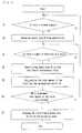
- Fig. 3 is a flow chart of a computer program that may be used for the flow controller of Fig. 2;
- Fig. 4 is a flow chart of another computer program that may be used for the flow controller of Fig. 2;
- Fig. 5 shows prior art; and
- Fig. 6 shows a drip-detecting device that may be used for the apparatus of Fig. 1.
- An apparatus which embodies the invention in one preferred form will now be described with reference to Figs. 1 and 2.
- In Fig. 1 a
vial 10 is hung upside down on a stand (not shown). Thevial 10 is filled with a fluid, such as blood, a nutritive solution, or a Ringer's solution, to be administered in drips into a vein of a patient. Thevial 10 is stopped by acork plug 12. A needle projecting upward from atube 14 is inserted into thecork plug 12. The fluid flows through the needle into thetube 14. A drip-feed bottle 18 is connected to the lower end of thetube 14. The fluid that has flowed into thetube 14 drips into the drip-feed bottle 18. A flexible fluid-supply pipe 20, such as a vinyl pipe, is connected to the lower end of the drip-feed bottle 18. An intravenous needle (not shown) is connected to the lower end of thepipe 20. From thebottle 18, drips of the fluid flow through thepipe 20 into the intravenous needle. - A
microphone 34 is located below thebottle 18, and is positioned by the side of thepipe 20. Themicrophone 34 detects the sound waves produced by a drip of the fluid falling into the drip-feed bottle 18. For example, a microphone detecting sound waves within the range of 20 cycles to 70 cycles per second may be used. - Below the
microphone 34 is located adevice 36 for constricting thepipe 20 to adjust the rate of flow of the fluid. The constrictingdevice 36 comprises an element (not shown) to constrict thepipe 20 directly and a stepping motor (not shown) to operate the constricting element. Themicrophone 34 is electrically connected to aflow controller 38. The sound waves detected and converted into an electrical signal by themicrophone 34 are input to theflow controller 36 via an amplifier (not shown) and a frequency discriminator (not shown). Aclock 40 is also connected to theflow controller 38. From theclock 40 the current time is always input to theflow controller 38. Theflow controller 38 sends an electrical signal to the constrictingdevice 36 through a transmission line 42 in order to rotate the stepping motor of the constricting device. - Referring to Fig. 2, the
flow controller 38 comprises aninput port 46, amicrocomputer 44, and anoutput port 48. The electrical signal from themicrophone 34, as well as a time signal from theclock 40, is input to theinput port 46. Themicrocomputer 44 includes aCPU 50, aRAM 52, and aROM 54. A program to control theCPU 50 is written in theROM 54. In accordance with this program theCPU 50 receives necessary data from theinput port 46 or receives or sends data from or to theRAM 52, and performs necessary arithmetic operations. TheCPU 50 processes data as required, and outputs it to theoutput port 48. Theoutput port 48 includes a latching circuit which receives an output port signal sent from theCPU 50 through atransmission line 58, and stores the data temporarily and outputs it to a digital-to-analog converter 60. Theconverter 60 converts the data from theoutput port 48 into an analog signal. The analog signal is output into the constrictingdevice 36 to control the stepping motor thereof. - The program written in the
ROM 54 is shown in Fig. 3. When the program starts, step 1 is performed to cause theCPU 50 to send a port-specifying signal to theinput port 46 through atransmission line 56 and check to see if there is a signal of detection of a drip (i.e., an electrical signal output from the microphone 34) in theinput port 46. If there is one, it is input to theCPU 50. If not, program execution goes back to START. In step 2 theCPU 50 sends a port signal to theinput port 46, and reads the time input to theinput port 46 from theclock 40. In step 3 it is determined whether there are a total of two or more time readings, including that taken immediately before this, in theCPU 50. If not (it means that the drip detected in step 1 is the first drip), execution goes back to START. If yes,step 4 is performed. Instep 4 theCPU 50 subtracts the preceding time (i.e., the time read in step 2 during the preceding execution of the program) from the current time read in step 2 (i.e., the most recent time reading) to determine the interval of time at which the intravenous fluid has dripped from thetube 14 into the drip-feed bottle 18. Also instep 4, based on data stored in theRAM 52, theCPU 50 calculates the actual rate at which the intravenous fluid drips from thetube 14 into the drip-feed bottle 18. Instep 5, from the actual rate obtained instep 4 and a predetermined rate stored in thecomputer 44 in advance, a correction value is calculated . Instep 6, based on the correction vale obtained instep 5, the amount by which to constrict thesupply pipe 20 or to release thesupply pipe 20 from constriction is calculated. Also instep 6, a signal indicative of that amount is sent to theoutput port 48, and is output thence to the D/A converter 60 and converted into an analog signal thereby. The analog signal is output to the stepping motor of the constrictingdevice 36. Whenstep 6 has been completed, program execution goes back to START. - In accordance with the invention, the amount of an intravenous fluid to be administered to a patient may be programmed in advance. If such an amount has been programmed in advance, the program of Fig. 3 has the following additional steps. Between steps 2 and 3 the total amount of the intravenous fluid that has dripped into the
bottle 18 is calculated, and afterstep 6 that total amount is compared with the programmed amount. Then, if the actual total amount is smaller than the programmed amount, execution goes back to step 1. When the programmed amount is reached, a signal is output to the constrictingdevice 36 to cause the constrictingdevice 36 to constrict thesupply pipe 20 such that the flow of intravenous fluid is stopped. Thereupon the program is completed. - In addition, in accordance with the invention, the period of time for which an intravenous fluid is to De administered to a patient may be programmed in advance. If such a period of time has been programmed in advance, the program of Fig. 3 has the following additional steps. Measurement of time that elapses is started when the first signal of detection of a drip is detected by the CPU 50 (in step 2). After
step 6, the time that has actually elapsed is compared with the programmed time. Then, if the actual time that has elapsed is shorter than the programmed period of time, execution goes back to step 1. When the programmed period of time is reached, a signal is output to the constrictingdevice 36 to cause the constrictingdevice 36 to constrict thesupply pipe 20 such that the flow of intravenous fluid is stopped. Thereupon the program is completed. - Fig. 4 shows a program for causing an intravenous fluid to drip at predetermined regular intervals of time. When this program is started, step 1 is performed to determine whether there is a "release signal", or a signal to rotate the stepping motor of the constricting
device 36 such that thesupply pipe 20 is released from constriction. If not, execution goes back to START. If there is one, step 2 is performed to rotate the stepping motor for a predetermined angle such that thesupply pipe 20 is released from constriction. In step 3 theCPU 50 checks to see if there is a signal of detection of a drip (of the intravenous fluid) in theinput port 46. If not, execution goes back to step 2. If there is one, it is input to theCPU 50. Then, instep 4 the stepping motor is so rotated as to constrict thesupply pipe 20 such that the flow of intravenous fluid is stopped (by the constricting device 36). Instep 5 the total amount of intravenous fluid that has dripped from thetube 14 into thebottle 18 is calculated. Instep 6 it is determined whether a programmed total amount of intravenous fluid has been reached. If not, execution goes back to START. If yes, step 7 is performed to stop the fluid from dripping into thebottle 18 and give an alarm. Thereupon the program is completed. - If desired, a drip-detecting device of Fig. 6 may be used for the construction of Fig. 1. The drip-detecting device of Fig. 6 includes a pair of
opposed clipping elements supply pipe 20 between. The two clipping elements are biased toward each other by means of a spring (not shown). Anair bag 24 is connected to the inside of oneclipping element 22a, while acushioning element 28 is connected to the inside of theother clipping element 22b. Both theair bag 24 and thecushioning element 28 are of elastic material. Amicrophone 34 is located in an opening of theclipping element 22a and is connected to the outside of theair bag 24. Since the two clipping elements are biased toward each other, theair bag 24 attaches very closely to thesupply pipe 20. Thus, if such a drip-detecting device is used, the sound waves, or vibration, produced by the intravenous fluid dripping into thebottle 18 is transmitted, without fail, to themicrophone 34 through theair bag 24. In addition, it will be appreciated that such a drip-detecting device can be very easily connected to or removed from thesupply pipe 20.
Claims (10)
- An apparatus for controlling the rate of dripping of an intravenous fluid comprising- drip-detectinq means for detecting that an intravenous fluid has dripped into a drip-feed bottle (18),- a clock (40) for measuring the time and indicating the current time,- constricting means (36) connected to a fluid-supply pipe (20) extending from the bottle (18) in a downstream direction, for constricting the supply pipe (20), and- a flow controller (38) for controlling the amount of constriction of the supply pipe (20) by the constricting means (36), based on a signal of detection of a drip from the drip-detecting means and a time signal from the clock (40),characterized in that the drip detecting means is adapted to detect a variation in pressure caused by each of the drops of the intravenous fluid dripping into the bottle (18).
- Apparatus in accordance with claim 1, characterized in that the drip-detecting means comprises a microphone (34) that detects sound waves produced by the intravenous fluid dripping into the bottle (18).
- Apparatus in accordance with claim 1, characterized in that the drip-detecting means comprises means for detecting vibrations caused by the intravenous fluid dripping into the bottle (18).
- Apparatus in accordance with any of claims 1 to 3,
characterized in that the drip-detecting means comprises- a pair of clipping elements (22a, 22b) between which the supply pipe (20) is located and which are biased toward each other by means of a spring, and- an air bag (24) connected to the inside of one of the clipping elements and pressed against the supply pipe (20),whereby the means for detecting the variation in pressure caused by the intravenous fluid dripping into the bottle (18) are connected to the air bag (24). - Apparatus in accordance with any of claims 1 to 4,
characterized in that the flow controller (38) includes- means for determining the interval of time at which the intravenous fluid has dripped into the bottle (18), based on signals of detection of drips from the drip-detecting means,- means for calculating the actual rate of dripping of the intravenous fluid into the bottle (18), based on said interval of time, and for comparing said actual rate and a programmed dripping rate and calculating a correction value by which said interval of time is adjusted, and- means for calculating an amount by which the supply pipe (20) is to be constricted, based on said correction value, and for outputting to the constricting means (36) a signal to constrict the supply pipe (20) by said amount. - Apparatus in accordance with claim 5, characterized in that the flow controller (38) further includes- a means for calculating the total amount of the intravenous fluid that has dripped into the bottle (18), based on the signals of detection of drips from the drip-detecting means, and- means for outputting to the constricting means (36) a stop signal to cause the constricting means (36) to constrict the supply pipe (20) such that the intravenous fluid is stopped from dripping, when a programmed total amount of the intravenous fluid to be administered to a patient has been reached.
- Apparatus in accordance with claim 6, characterized in that the flow controller (38) further includes means for giving an alarm after said stop signal has been output.
- Apparatus in accordance with claim 5, characterized in that the flow controller (38) further includes- means for calculating the total period of time for which the intravenous fluid has dripped, based on the signals of detection of drips from the drip-detecting means, and- means for outputting to the constricting means (36) a stop signal to cause the constricting means (36) to constrict the supply pipe (20) such that the intravenous fluid is stopped from dripping, when a programmed total period of time has been reached.
- Apparatus in accordance with claim 8, characterized in that the flow controller further includes means for giving an alarm after said stop signal has been output.
- Apparatus in accordance with any of claims 1 to 9,
characterized in that the flow controller (38) includes- means for outputting to the constricting means (36) a signal to rotate a steppinq motor of the constricting means (36) for a predetermined angle such that the supply pipe (20) is released from constriction by a predetermined amount, and- means for outputting to the constricting means (36) a signal to rotate the stepping motor of the constricting means (36) such that the supply pipe (20) is constricted, based on signals of detection of drips from the drip-detecting means.
Applications Claiming Priority (4)
| Application Number | Priority Date | Filing Date | Title |
|---|---|---|---|
| JP237016/91 | 1991-08-23 | ||
| JP3237016AJPH07144020A (en) | 1991-08-23 | 1991-08-23 | Instilation rate controller for transfusion |
| JP3246916AJPH0749053B2 (en) | 1991-08-30 | 1991-08-30 | Submerged liquid drop detector |
| JP246916/91 | 1991-08-30 |
Publications (3)
| Publication Number | Publication Date |
|---|---|
| EP0529569A2 EP0529569A2 (en) | 1993-03-03 |
| EP0529569A3 EP0529569A3 (en) | 1993-11-24 |
| EP0529569B1true EP0529569B1 (en) | 1996-07-24 |
Family
ID=26533003
Family Applications (1)
| Application Number | Title | Priority Date | Filing Date |
|---|---|---|---|
| EP92114416AExpired - LifetimeEP0529569B1 (en) | 1991-08-23 | 1992-08-24 | Apparatus for controlling the rate of dripping of intravenous fluid |
Country Status (4)
| Country | Link |
|---|---|
| US (1) | US5254102A (en) |
| EP (1) | EP0529569B1 (en) |
| KR (1) | KR930003929A (en) |
| DE (1) | DE69212405T2 (en) |
Families Citing this family (39)
| Publication number | Priority date | Publication date | Assignee | Title |
|---|---|---|---|---|
| KR100403695B1 (en)* | 2000-11-09 | 2003-11-01 | 가부시끼가이샤메디코스히라타 | Portable Automatic Venous Infusion System |
| KR100786667B1 (en)* | 2001-05-04 | 2007-12-21 | 오리온피디피주식회사 | High-voltage output stage circuit of the drive trapping level shifter type plasma display panel driving circuit |
| US20190357827A1 (en) | 2003-08-01 | 2019-11-28 | Dexcom, Inc. | Analyte sensor |
| US8626257B2 (en) | 2003-08-01 | 2014-01-07 | Dexcom, Inc. | Analyte sensor |
| US20080119703A1 (en) | 2006-10-04 | 2008-05-22 | Mark Brister | Analyte sensor |
| US7591801B2 (en) | 2004-02-26 | 2009-09-22 | Dexcom, Inc. | Integrated delivery device for continuous glucose sensor |
| US8886273B2 (en) | 2003-08-01 | 2014-11-11 | Dexcom, Inc. | Analyte sensor |
| US7920906B2 (en) | 2005-03-10 | 2011-04-05 | Dexcom, Inc. | System and methods for processing analyte sensor data for sensor calibration |
| US9247900B2 (en) | 2004-07-13 | 2016-02-02 | Dexcom, Inc. | Analyte sensor |
| US8364230B2 (en) | 2006-10-04 | 2013-01-29 | Dexcom, Inc. | Analyte sensor |
| US8287453B2 (en) | 2003-12-05 | 2012-10-16 | Dexcom, Inc. | Analyte sensor |
| US11633133B2 (en) | 2003-12-05 | 2023-04-25 | Dexcom, Inc. | Dual electrode system for a continuous analyte sensor |
| US8425417B2 (en) | 2003-12-05 | 2013-04-23 | Dexcom, Inc. | Integrated device for continuous in vivo analyte detection and simultaneous control of an infusion device |
| US8423114B2 (en) | 2006-10-04 | 2013-04-16 | Dexcom, Inc. | Dual electrode system for a continuous analyte sensor |
| US8364231B2 (en) | 2006-10-04 | 2013-01-29 | Dexcom, Inc. | Analyte sensor |
| US8425416B2 (en) | 2006-10-04 | 2013-04-23 | Dexcom, Inc. | Analyte sensor |
| US8808228B2 (en) | 2004-02-26 | 2014-08-19 | Dexcom, Inc. | Integrated medicament delivery device for use with continuous analyte sensor |
| WO2009048462A1 (en) | 2007-10-09 | 2009-04-16 | Dexcom, Inc. | Integrated insulin delivery system with continuous glucose sensor |
| US8886272B2 (en) | 2004-07-13 | 2014-11-11 | Dexcom, Inc. | Analyte sensor |
| US7783333B2 (en) | 2004-07-13 | 2010-08-24 | Dexcom, Inc. | Transcutaneous medical device with variable stiffness |
| US7654956B2 (en) | 2004-07-13 | 2010-02-02 | Dexcom, Inc. | Transcutaneous analyte sensor |
| JP5147407B2 (en) | 2004-10-21 | 2013-02-20 | ノボ・ノルデイスク・エー/エス | Infusion device with processor for collecting release information |
| CN101405738B (en)* | 2006-03-20 | 2011-11-23 | 诺沃-诺迪斯克有限公司 | Method and electronic module for wirelessly monitoring the operation of a mechanical drug delivery device |
| US8449464B2 (en) | 2006-10-04 | 2013-05-28 | Dexcom, Inc. | Analyte sensor |
| US8275438B2 (en) | 2006-10-04 | 2012-09-25 | Dexcom, Inc. | Analyte sensor |
| US8478377B2 (en) | 2006-10-04 | 2013-07-02 | Dexcom, Inc. | Analyte sensor |
| US8562528B2 (en) | 2006-10-04 | 2013-10-22 | Dexcom, Inc. | Analyte sensor |
| US8447376B2 (en) | 2006-10-04 | 2013-05-21 | Dexcom, Inc. | Analyte sensor |
| US8298142B2 (en) | 2006-10-04 | 2012-10-30 | Dexcom, Inc. | Analyte sensor |
| WO2008154312A1 (en) | 2007-06-08 | 2008-12-18 | Dexcom, Inc. | Integrated medicament delivery device for use with continuous analyte sensor |
| US8396528B2 (en) | 2008-03-25 | 2013-03-12 | Dexcom, Inc. | Analyte sensor |
| US8531517B2 (en)* | 2010-07-15 | 2013-09-10 | Kai Tao | IV monitoring by video and image processing |
| KR101058539B1 (en)* | 2011-02-23 | 2011-08-23 | 이두용 | Sap flow rate controller, Sap flow rate control set and Sap flow rate control method |
| EP2697650B1 (en) | 2011-04-15 | 2020-09-30 | Dexcom, Inc. | Advanced analyte sensor calibration and error detection |
| US11464905B2 (en) | 2013-02-25 | 2022-10-11 | Shift Labs, Inc. | Monitoring device including an emitter emitting electromagnetic radiation and a detector positioned to receive the radiation to determine one or more rolling average flow rates |
| CA2940284C (en) | 2013-02-25 | 2021-02-09 | Shift Labs, Inc. | Device, method, and system for monitoring the delivery of fluids through a drip chamber |
| CN108472446A (en)* | 2016-02-04 | 2018-08-31 | 金宙科技有限公司 | liquid flow measuring device |
| US20190120785A1 (en) | 2017-10-24 | 2019-04-25 | Dexcom, Inc. | Pre-connected analyte sensors |
| US11331022B2 (en) | 2017-10-24 | 2022-05-17 | Dexcom, Inc. | Pre-connected analyte sensors |
Family Cites Families (18)
| Publication number | Priority date | Publication date | Assignee | Title |
|---|---|---|---|---|
| US2807012A (en)* | 1953-06-08 | 1957-09-17 | Schwarz Herbert | Transfusion monitoring device |
| GB2021290B (en)* | 1978-05-19 | 1982-10-27 | Frenshore Ltd | Automatic flow control |
| US4261388A (en)* | 1978-05-19 | 1981-04-14 | Frenshore Ltd. | Drop rate controller |
| EP0018817A1 (en)* | 1979-04-30 | 1980-11-12 | Peter Gilbert Lale | Method and apparatus for measuring drip rate |
| US4460353A (en)* | 1980-09-08 | 1984-07-17 | Imed Corporation | Drop controller |
| JPS57211361A (en)* | 1981-06-23 | 1982-12-25 | Terumo Corp | Liquid injecting apparatus |
| JPS5836562A (en)* | 1981-08-28 | 1983-03-03 | テルモ株式会社 | Control apparatus for drip amount |
| US4507112A (en)* | 1982-04-05 | 1985-03-26 | Ipco Corporation | Infusion monitor |
| US4496351A (en)* | 1982-04-05 | 1985-01-29 | Ipco Corporation | Infusion monitor |
| US4645489A (en)* | 1982-11-30 | 1987-02-24 | Beta Phase, Inc. | Fluid delivery apparatus with shape-memory flow control element |
| US4493710A (en)* | 1983-11-14 | 1985-01-15 | Ivy Medical, Inc. | Intravenous drip rate control device |
| DE3404144A1 (en)* | 1984-02-07 | 1985-08-08 | "gutta" Gesellschaft für Infusionstechnik mbH, 2000 Hamburg | MONOLITHIC MINIATURIZED GRAVITY INFUSION CONTROL UNIT |
| US4634426A (en)* | 1984-12-11 | 1987-01-06 | Baxter Travenol Laboratories | Medical infusion controller and user interface |
| US4718896A (en)* | 1986-01-10 | 1988-01-12 | Abbott Laboratories | Apparatus and method for controlling the flow of fluid through an administration set |
| NL8802307A (en)* | 1987-12-17 | 1989-07-17 | Mr W M H Kerbosch B V Handelen | DEVICE FOR CONTROLLING THE FLOW RATE OF AN INFUSION FLUID IN AN INFUSION SYSTEM. |
| US4946439A (en)* | 1988-08-15 | 1990-08-07 | Critikon, Inc. | Dual source parenteral infusion system with secondary infusion module |
| JPH02120628A (en)* | 1988-10-31 | 1990-05-08 | Mitsubishi Electric Corp | Drip monitoring device |
| JPH03231680A (en)* | 1990-02-06 | 1991-10-15 | Terumo Corp | Drip detector and drip infusion alarming apparatus with this detector and apparatus for controlling amount of drip |
- 1992
- 1992-08-22KRKR1019920015093Apatent/KR930003929A/ennot_activeCeased
- 1992-08-24EPEP92114416Apatent/EP0529569B1/ennot_activeExpired - Lifetime
- 1992-08-24USUS07/933,811patent/US5254102A/ennot_activeExpired - Fee Related
- 1992-08-24DEDE69212405Tpatent/DE69212405T2/ennot_activeExpired - Fee Related
Also Published As
| Publication number | Publication date |
|---|---|
| EP0529569A3 (en) | 1993-11-24 |
| DE69212405T2 (en) | 1997-01-02 |
| KR930003929A (en) | 1993-03-22 |
| DE69212405D1 (en) | 1996-08-29 |
| EP0529569A2 (en) | 1993-03-03 |
| US5254102A (en) | 1993-10-19 |
Similar Documents
| Publication | Publication Date | Title |
|---|---|---|
| EP0529569B1 (en) | Apparatus for controlling the rate of dripping of intravenous fluid | |
| US6952963B2 (en) | Method for detecting a liquid level in a container in a circuit and a dialysis machine for actuating the method | |
| JP3321620B2 (en) | Apparatus and method for detection of air in a liquid delivery system | |
| US4221004A (en) | Adjustable ultrasonic level measurement device | |
| US5256155A (en) | Drop detection method and apparatus | |
| US4174637A (en) | Pressure monitoring system | |
| EP1182452B1 (en) | Method for ultrasonic detection of air bubbles | |
| US4703314A (en) | Empty container detector with drop sensor | |
| US4509943A (en) | Infusion control apparatus | |
| US5135485A (en) | Capacitance-type fluid level sensor for i.v. and catheter bags | |
| EP0554716A1 (en) | Fluid line condition detection | |
| EP0346548A1 (en) | Empty container detector | |
| US5060654A (en) | Identification method for the cuff type of a sphygmomanometer | |
| CN101189509A (en) | Method and apparatus for monitoring the presence of air in a liquid stream by means of ultrasound | |
| JPH0649068B2 (en) | Device for detecting abnormalities in intravascular infusion | |
| JPH11287817A (en) | Apparatus and method for measuring velocity | |
| EP2876418A1 (en) | Optical flow measuring device and method of operation | |
| EP0981201B1 (en) | Zero crossing detector and method of determining a zero crossing point | |
| DE69223662D1 (en) | Electronic blood pressure monitor | |
| US6786633B2 (en) | Method and arrangement for acoustically determining a fluid temperature | |
| JP2007530933A (en) | Zero-crossing detection of ultrasonic signals with variable threshold | |
| JPH07144020A (en) | Instilation rate controller for transfusion | |
| US4929825A (en) | Means for detecting damage to the card connecting the photosensor and main body pulsimeter | |
| GB2031158A (en) | Flow measurement | |
| JPH0898885A (en) | Electronic drip management drip bottle |
Legal Events
| Date | Code | Title | Description |
|---|---|---|---|
| PUAI | Public reference made under article 153(3) epc to a published international application that has entered the european phase | Free format text:ORIGINAL CODE: 0009012 | |
| AK | Designated contracting states | Kind code of ref document:A2 Designated state(s):DE FR GB IT SE | |
| 17P | Request for examination filed | Effective date:19930605 | |
| PUAL | Search report despatched | Free format text:ORIGINAL CODE: 0009013 | |
| AK | Designated contracting states | Kind code of ref document:A3 Designated state(s):DE FR GB IT SE | |
| 17Q | First examination report despatched | Effective date:19941202 | |
| GRAH | Despatch of communication of intention to grant a patent | Free format text:ORIGINAL CODE: EPIDOS IGRA | |
| GRAH | Despatch of communication of intention to grant a patent | Free format text:ORIGINAL CODE: EPIDOS IGRA | |
| GRAA | (expected) grant | Free format text:ORIGINAL CODE: 0009210 | |
| AK | Designated contracting states | Kind code of ref document:B1 Designated state(s):DE FR GB IT SE | |
| PG25 | Lapsed in a contracting state [announced via postgrant information from national office to epo] | Ref country code:IT Free format text:LAPSE BECAUSE OF FAILURE TO SUBMIT A TRANSLATION OF THE DESCRIPTION OR TO PAY THE FEE WITHIN THE PRE;WARNING: LAPSES OF ITALIAN PATENTS WITH EFFECTIVE DATE BEFORE 2007 MAY HAVE OCCURRED AT ANY TIME BEFORE 2007. THE CORRECT EFFECTIVE DATE MAY BE DIFFERENT FROM THE ONE RECORDED.SCRIBED TIME-LIMIT Effective date:19960724 | |
| REF | Corresponds to: | Ref document number:69212405 Country of ref document:DE Date of ref document:19960829 | |
| PG25 | Lapsed in a contracting state [announced via postgrant information from national office to epo] | Ref country code:SE Effective date:19961024 | |
| ET | Fr: translation filed | ||
| PLBE | No opposition filed within time limit | Free format text:ORIGINAL CODE: 0009261 | |
| 26N | No opposition filed | ||
| PGFP | Annual fee paid to national office [announced via postgrant information from national office to epo] | Ref country code:GB Payment date:19970813 Year of fee payment:6 | |
| PGFP | Annual fee paid to national office [announced via postgrant information from national office to epo] | Ref country code:FR Payment date:19970827 Year of fee payment:6 | |
| PGFP | Annual fee paid to national office [announced via postgrant information from national office to epo] | Ref country code:DE Payment date:19971031 Year of fee payment:6 | |
| PG25 | Lapsed in a contracting state [announced via postgrant information from national office to epo] | Ref country code:GB Free format text:LAPSE BECAUSE OF NON-PAYMENT OF DUE FEES Effective date:19980824 | |
| GBPC | Gb: european patent ceased through non-payment of renewal fee | Effective date:19980824 | |
| PG25 | Lapsed in a contracting state [announced via postgrant information from national office to epo] | Ref country code:FR Free format text:LAPSE BECAUSE OF NON-PAYMENT OF DUE FEES Effective date:19990430 | |
| PG25 | Lapsed in a contracting state [announced via postgrant information from national office to epo] | Ref country code:DE Free format text:LAPSE BECAUSE OF NON-PAYMENT OF DUE FEES Effective date:19990601 | |
| REG | Reference to a national code | Ref country code:FR Ref legal event code:ST |