EP0529297B1 - Needle park - Google Patents
Needle parkDownload PDFInfo
- Publication number
- EP0529297B1 EP0529297B1EP92112380AEP92112380AEP0529297B1EP 0529297 B1EP0529297 B1EP 0529297B1EP 92112380 AEP92112380 AEP 92112380AEP 92112380 AEP92112380 AEP 92112380AEP 0529297 B1EP0529297 B1EP 0529297B1
- Authority
- EP
- European Patent Office
- Prior art keywords
- needle
- wall
- end section
- park
- needle park
- Prior art date
- Legal status (The legal status is an assumption and is not a legal conclusion. Google has not performed a legal analysis and makes no representation as to the accuracy of the status listed.)
- Expired - Lifetime
Links
- 239000000463materialSubstances0.000claimsdescription6
- 230000000295complement effectEffects0.000claimsdescription4
- 238000000926separation methodMethods0.000claimsdescription4
- 239000004743PolypropyleneSubstances0.000claimsdescription2
- -1polypropylenePolymers0.000claimsdescription2
- 229920001155polypropylenePolymers0.000claimsdescription2
- 229920001169thermoplasticPolymers0.000claimsdescription2
- 239000004416thermosoftening plasticSubstances0.000claimsdescription2
- 239000006260foamSubstances0.000description4
- 238000004519manufacturing processMethods0.000description4
- 238000000465mouldingMethods0.000description2
- 239000004033plasticSubstances0.000description2
- 238000010276constructionMethods0.000description1
- 230000001419dependent effectEffects0.000description1
- 238000003780insertionMethods0.000description1
- 230000037431insertionEffects0.000description1
- 238000012986modificationMethods0.000description1
- 230000004048modificationEffects0.000description1
- 238000005192partitionMethods0.000description1
- 238000003856thermoformingMethods0.000description1
- 239000012815thermoplastic materialSubstances0.000description1
Images
Classifications
- A—HUMAN NECESSITIES
- A61—MEDICAL OR VETERINARY SCIENCE; HYGIENE
- A61B—DIAGNOSIS; SURGERY; IDENTIFICATION
- A61B17/00—Surgical instruments, devices or methods
- A61B17/04—Surgical instruments, devices or methods for suturing wounds; Holders or packages for needles or suture materials
- A61B17/06—Needles ; Sutures; Needle-suture combinations; Holders or packages for needles or suture materials
- A61B17/06114—Packages or dispensers for needles or sutures
- A61B17/06133—Packages or dispensers for needles or sutures of parallelepipedal shape, e.g. made of rectangular or slightly oval panels
Definitions
- This inventionrelates to a needle park for securing needles, and, more particularly, to a needle park for a package that holds one or more surgical needles and sutures.
- a simple holder devicei.e., needle park
- the needleeither pierces the foam or is inserted into a slit cut into the foam.
- a disadvantage of the foam stripis that it is a separate element from the rest of the package and must be adhered to the base of the package, requiring an additional operation during package manufacture.
- U.S. Patent 4,961,498, issued October 9, 1990, to Kalinski et al.discloses an alternate needle park comprising a molded post and adjacent molded rail, which may both be formed on the floor of a suture package.
- the post and railare separated by a distance that is slightly smaller than the diameter of a needle to be held.
- the railflexes slightly, and the needle is held in place by contact on either side of the needle with the post and the rail.
- This designis limited to holding needles of a single diameter.
- a somewhat similar needle park, which can hold a narrow range of needle diameters,is disclosed in U.S. Patent 4,424,898.
- a needle park adapted to hold needles having a broad range of diametersconsists of a raised platform that has two string-like lengths arrayed parallel to each other, with their ends affixed to the platform.
- the stringshave notched undersides and the platform is open below the strings. Needles are parked by insertion on top of the platform and under the strings. The notches on the strings prevent the needles from sliding along the length of the strings.
- This type of parkcan retain needles having a range of diameters; however, it depends on the flexibility of the strings and is not as simple or inexpensive to manufacture as are other needle parks.
- U.S. Patent 4,967,902issued November 6, 1990 to Sobel et al. discloses another type of needle park, comprising a wall that extends upward from the base of a needle package and that is interrupted by a gap into which the needle may be inserted. That type of park can only hold a needle whose diameter is substantially the same as the width of the gap between the wall ends.
- the wall endscan be undercut near the base and the base beneath the gap can be removed, which permits the wall ends to flex and bend, thereby accommodating a somewhat wider range of needle diameters.
- the range of needle diameters that can be held securelyis limited, however.
- U.S. Patent 4,573,575shows a plastic needle package including needle accommodating compartments to accomodate and retain needle heads with different diameters. This is achieved by adjusting locally impressions in partition and side walls to the relevant needle head diameters so that nose-shaped protrusions of material that form projecting stops can be adjusted to the type of needle to be packaged. This adjustment is accomplished in using a soft plastic.
- the needle parkcomprises the features as defined in claim 1.
- the needle park of the present inventionis adapted for being molded as part of a needle and suture package which permits the packages to be made simply and inexpensively. At the same time, a single park can hold securely a needle whose diameter may vary over a broad range.
- Fig. 1depicts a surgical needle and suture package of the present invention.
- Fig. 2is an isometric view of a needle park of the present invention.
- Fig. 3shows a needle secured in the needle park of Fig. 2.
- Fig. 4shows a needle secured in a needle park of another embodiment of this invention.
- the needle park of the present inventionis adapted to securely anchor a surgical needle whose diameter is anywhere within a broad range of diameters.
- the needle parkis typically part of a needle and suture package, and it does not unduly interfere with removal of the needle from the package.
- the needle parkis economical to manufacture.
- a suture package using this needle parkcan be manufactured by molding, stamping, or thermoforming of thermoplastic materials.
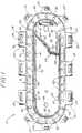
- Fig. 1is a plan view of a one-piece needle and suture package of the present invention.
- the package 10includes a central floor area 18 which is surrounded by an outer oval channel 12 having two opposing straight sections connected by two semicircular end sections.
- the channelis defined by an inner wall 14 which extends upwardly from the floor area.
- the bottom and outer periphery of the channel 12is defined by a curved section 16 of the package, which extends outwardly from the inner wall 14 at the level of the floor 18 and curves upwardly to approximately the elevation of the inner wall 14.
- Attached at the outer periphery of the curved section 16are a plurality of hinged doors 20.
- the doorsare hinged at an elevation which is slightly below the uppermost elevation of the outer periphery of the curved section and the inner wall so that, when the doors are folded over the channel and latched in place, the upper surfaces of the doors will align with the upper elevation of the outer periphery and inner wall.
- Formed in each dooris a portion of the door locking means 24, including a latch opening 26 bounded by a door latch projection 28 and two fins 36.
- a needle parkLocated inside the oval channel is a needle park, an enlarged view of which appears in Fig. 2 and is described below. Adjacent the needle park is a relief flap 50 defined by a cutout 52. A portion of the inner wall 14 is eliminated in the vicinity of the needle park to form a vent 40 in the channel wall through which the suture of the needle accesses the channel between doors 20' and 20''.
- the bottom of the channel 12 formed by the curved section 16is periodically perforated by holes 80 and 82 around the circumference of the channel. These holes are used for assembling the package with a suture and, optionally, a needle, as follows:
- Package 10is placed on an assembly platform that has a number of upwardly extending pins. Two of the pins are aligned to extend upward through holes 66 and 68 in the center of the package to retain the package in its assembly position on the platform. Eight other pins extend upward and are aligned to pass through the holes 82 of the channel.
- the platformis open beneath the remaining channel holes 80 and a vacuum source below the platform draws air through the holes 80.
- the needleWith the package so emplaced, the needle is located in the needle holder, and the suture is looped above the pin extending through hole 66 then downward through the vent 40 and into the channel. The suture is then wound in a clockwise direction around the pins which extend through the channel holes 82.
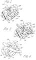
- Fig. 2shows an enlarged isometric view of needle park 54.
- the needle parkincludes a first wall 55 and a second wall 56, both generally perpendicular to the floor 18 and separated by a gap 57.
- Cutout 58separates end section 59 from base 18 and separates all but a top segment of end section 59 from the rest of wall 55.
- the upper surface of the top segment and the top of wall 56, on the opposite side of gap 57are tapered to guide a needle.
- the separation of end section 59 from base 18is a result of extending cutout 58 downward to include the region of base 18 that lies between walls 55 and 56.
- base 18remains intact, but the bottom of end section 59 is cut off.
- the embodiment shown, with the cutout including a portion of the base,is preferred, because it is easier to form by molding, a preferred method of fabricating package 10.
- the facing surfaces of walls 55 and 56preferably have complementary shapes that maintain substantially constant separation over their surfaces.
- the facing surface of wall 55has a "V"-shaped groove 60 that runs vertically from the top to the bottom of the wall, and the facing surface of wall 56 has a complementary top-to-bottom extension 61.
- An advantage of providing non-planar complementary faces on the adjoining surfaces of the wallsis that a very small effective separation (essentially zero) can be achieved, which, in turn, permits very thin needles to be held.
- the "3-point contact" (to the needle) that is provided by the facing surfaces of Fig. 2helps to prevent a needle from sliding in the needle park. Needle sliding can be a particular problem when there are closely adjoining needle parks - as shown in Fig. 1. In that case, sliding can cause the needles in adjoining parks to come into contact with each other, which is undesirable.
- Fig. 3shows part of a needle 62 being held in a needle park of the type shown in Fig. 2.
- the top segment of end section 59has become a pivot point and the bottom of end section 59 has been bent into cutout 58 to accommodate needle 62.
- the substantially fixed top segment and flexible bottom of end section 59combine to provide an "undercut" that minimizes the risk of the needle inadvertently backing out of the needle park.
- the floor area 63 that supports the needle on opposite sides of gap 57may be slightly raised, as shown in Figs. 2 and 3, to prevent the needle from sliding between floor 18 and the bottom of end section 59.
- Fig. 4shows another embodiment of a needle park of this invention, particularly adapted for holding large-diameter needles.
- the second wall 56also has a cutout 58A.
- both wallshave end sections with a top segment that provides a pivot point and a bottom that bends into a cutout.
- the two-cutout structureis more symmetrical, and thus permits the hinge formed by the top of the end section to be stiffer.
- the material of package 10 and of needle park 54is preferably a moldable thermoplastic.
- Polypropyleneis preferred, because of its flexibility, moldability, and ability to form a "living hinge" at end section 59.
- the dimensions of the elements of the needle park -e.g., gap width, size of cutout, dimensions of the groove and extension on the adjoining surfaces of the walls, etc. - are determined by the range of dimensions of the needles to be held and the mechanical characteristics of the needle park material - e.g., strength, flex modulus, memory, etc.
Landscapes
- Health & Medical Sciences (AREA)
- Surgery (AREA)
- Life Sciences & Earth Sciences (AREA)
- Medical Informatics (AREA)
- Animal Behavior & Ethology (AREA)
- Engineering & Computer Science (AREA)
- Biomedical Technology (AREA)
- Heart & Thoracic Surgery (AREA)
- Dentistry (AREA)
- Molecular Biology (AREA)
- Nuclear Medicine, Radiotherapy & Molecular Imaging (AREA)
- General Health & Medical Sciences (AREA)
- Public Health (AREA)
- Veterinary Medicine (AREA)
- Surgical Instruments (AREA)
- Materials For Medical Uses (AREA)
- Packaging Of Annular Or Rod-Shaped Articles, Wearing Apparel, Cassettes, Or The Like (AREA)
Description
- This invention relates to a needle park for securing needles, and, more particularly, to a needle park for a package that holds one or more surgical needles and sutures.
- Packages for surgical needles and sutures must, among other things, securely anchor the needles, yet permit them to be easily removed when they are to be used. A simple holder device (i.e., needle park) for accomplishing that consists of a foam strip adhered to the base of the package. The needle either pierces the foam or is inserted into a slit cut into the foam. A disadvantage of the foam strip is that it is a separate element from the rest of the package and must be adhered to the base of the package, requiring an additional operation during package manufacture.
- U.S. Patent 4,961,498, issued October 9, 1990, to Kalinski et al. discloses an alternate needle park comprising a molded post and adjacent molded rail, which may both be formed on the floor of a suture package. The post and rail are separated by a distance that is slightly smaller than the diameter of a needle to be held. When the needle is placed between the post and rail, the rail flexes slightly, and the needle is held in place by contact on either side of the needle with the post and the rail. This design is limited to holding needles of a single diameter. A somewhat similar needle park, which can hold a narrow range of needle diameters, is disclosed in U.S. Patent 4,424,898.
- A needle park adapted to hold needles having a broad range of diameters consists of a raised platform that has two string-like lengths arrayed parallel to each other, with their ends affixed to the platform. The strings have notched undersides and the platform is open below the strings. Needles are parked by insertion on top of the platform and under the strings. The notches on the strings prevent the needles from sliding along the length of the strings. This type of park can retain needles having a range of diameters; however, it depends on the flexibility of the strings and is not as simple or inexpensive to manufacture as are other needle parks.
- U.S. Patent 4,967,902, issued November 6, 1990 to Sobel et al. discloses another type of needle park, comprising a wall that extends upward from the base of a needle package and that is interrupted by a gap into which the needle may be inserted. That type of park can only hold a needle whose diameter is substantially the same as the width of the gap between the wall ends. To increase the range of needle diameters that can be held, the wall ends can be undercut near the base and the base beneath the gap can be removed, which permits the wall ends to flex and bend, thereby accommodating a somewhat wider range of needle diameters. The range of needle diameters that can be held securely is limited, however.
- This document discloses a needle park according the preamble of claim 1.
- U.S. Patent 4,573,575 shows a plastic needle package including needle accommodating compartments to accomodate and retain needle heads with different diameters. This is achieved by adjusting locally impressions in partition and side walls to the relevant needle head diameters so that nose-shaped protrusions of material that form projecting stops can be adjusted to the type of needle to be packaged. This adjustment is accomplished in using a soft plastic.
- In accordance with the present invention the needle park comprises the features as defined in claim 1.
- Further advantageous embodiments of the inventive needle park are defined in the following dependent claims.
- The needle park of the present invention is adapted for being molded as part of a needle and suture package which permits the packages to be made simply and inexpensively. At the same time, a single park can hold securely a needle whose diameter may vary over a broad range.
- Fig. 1 depicts a surgical needle and suture package of the present invention.
- Fig. 2 is an isometric view of a needle park of the present invention.
- Fig. 3 shows a needle secured in the needle park of Fig. 2.
- Fig. 4 shows a needle secured in a needle park of another embodiment of this invention.
- The needle park of the present invention is adapted to securely anchor a surgical needle whose diameter is anywhere within a broad range of diameters. The needle park is typically part of a needle and suture package, and it does not unduly interfere with removal of the needle from the package. At the same time, the needle park is economical to manufacture. Thus, a suture package using this needle park can be manufactured by molding, stamping, or thermoforming of thermoplastic materials.
- Fig. 1 is a plan view of a one-piece needle and suture package of the present invention. The
package 10 includes acentral floor area 18 which is surrounded by an outeroval channel 12 having two opposing straight sections connected by two semicircular end sections. The channel is defined by aninner wall 14 which extends upwardly from the floor area. The bottom and outer periphery of thechannel 12 is defined by acurved section 16 of the package, which extends outwardly from theinner wall 14 at the level of thefloor 18 and curves upwardly to approximately the elevation of theinner wall 14. Attached at the outer periphery of thecurved section 16 are a plurality of hingeddoors 20. The doors are hinged at an elevation which is slightly below the uppermost elevation of the outer periphery of the curved section and the inner wall so that, when the doors are folded over the channel and latched in place, the upper surfaces of the doors will align with the upper elevation of the outer periphery and inner wall. Formed in each door is a portion of the door locking means 24, including a latch opening 26 bounded by adoor latch projection 28 and twofins 36. When the door is closed overchannel 12, the top of thelatch post 30 engages the door latch opening 26 and the doorlatch projection 28 hooks around thelatch post projection 32 to lock the door in the closed position. - Located inside the oval channel is a needle park, an enlarged view of which appears in Fig. 2 and is described below. Adjacent the needle park is a
relief flap 50 defined by acutout 52. A portion of theinner wall 14 is eliminated in the vicinity of the needle park to form avent 40 in the channel wall through which the suture of the needle accesses the channel between doors 20' and 20''. - The bottom of the
channel 12 formed by thecurved section 16 is periodically perforated byholes Package 10 is placed on an assembly platform that has a number of upwardly extending pins. Two of the pins are aligned to extend upward throughholes holes 82 of the channel. The platform is open beneath theremaining channel holes 80 and a vacuum source below the platform draws air through theholes 80. With the package so emplaced, the needle is located in the needle holder, and the suture is looped above the pin extending throughhole 66 then downward through thevent 40 and into the channel. The suture is then wound in a clockwise direction around the pins which extend through thechannel holes 82. - Additional details regarding the construction of the suture package of Fig. 1 appear in U.S. Patent 4,967,902, incorporated herein by reference.
- Fig. 2 shows an enlarged isometric view of
needle park 54. The needle park includes afirst wall 55 and asecond wall 56, both generally perpendicular to thefloor 18 and separated by agap 57.Cutout 58 separatesend section 59 frombase 18 and separates all but a top segment ofend section 59 from the rest ofwall 55. Preferably the upper surface of the top segment and the top ofwall 56, on the opposite side ofgap 57, are tapered to guide a needle. - In the embodiment shown, the separation of
end section 59 frombase 18 is a result of extendingcutout 58 downward to include the region ofbase 18 that lies betweenwalls base 18 remains intact, but the bottom ofend section 59 is cut off. The embodiment shown, with the cutout including a portion of the base, is preferred, because it is easier to form by molding, a preferred method of fabricatingpackage 10. - The facing surfaces of
walls wall 55 has a "V"-shapedgroove 60 that runs vertically from the top to the bottom of the wall, and the facing surface ofwall 56 has a complementary top-to-bottom extension 61. An advantage of providing non-planar complementary faces on the adjoining surfaces of the walls is that a very small effective separation (essentially zero) can be achieved, which, in turn, permits very thin needles to be held. Furthermore, the "3-point contact" (to the needle) that is provided by the facing surfaces of Fig. 2 helps to prevent a needle from sliding in the needle park. Needle sliding can be a particular problem when there are closely adjoining needle parks - as shown in Fig. 1. In that case, sliding can cause the needles in adjoining parks to come into contact with each other, which is undesirable. - Fig. 3 shows part of a
needle 62 being held in a needle park of the type shown in Fig. 2. The top segment ofend section 59 has become a pivot point and the bottom ofend section 59 has been bent intocutout 58 to accommodateneedle 62. The substantially fixed top segment and flexible bottom ofend section 59 combine to provide an "undercut" that minimizes the risk of the needle inadvertently backing out of the needle park. For holding very-small-diameter needles, thefloor area 63 that supports the needle on opposite sides ofgap 57 may be slightly raised, as shown in Figs. 2 and 3, to prevent the needle from sliding betweenfloor 18 and the bottom ofend section 59. - Fig. 4 shows another embodiment of a needle park of this invention, particularly adapted for holding large-diameter needles. In this embodiment, the
second wall 56 also has acutout 58A. As a result, both walls have end sections with a top segment that provides a pivot point and a bottom that bends into a cutout. Compared to the embodiment shown in Fig. 3, the two-cutout structure is more symmetrical, and thus permits the hinge formed by the top of the end section to be stiffer. - The material of
package 10 and ofneedle park 54 is preferably a moldable thermoplastic. Polypropylene is preferred, because of its flexibility, moldability, and ability to form a "living hinge" atend section 59. The dimensions of the elements of the needle park - e.g., gap width, size of cutout, dimensions of the groove and extension on the adjoining surfaces of the walls, etc. - are determined by the range of dimensions of the needles to be held and the mechanical characteristics of the needle park material - e.g., strength, flex modulus, memory, etc. - The invention having been described in specific detail and the manner in which it may be carried out having been exemplified, it will be readily apparent to those skilled in the art that innumerable variations, applications, modifications, and extensions of the basic principles involved may be made without departing from the scope of the invention.
Claims (8)
- A needle park (54) for securing a needle (62), comprising a generally planar base (18) on which is a first wall (55) and a second wall (56), generally perpendicular to the base (18) and collinear aligned, said first wall (55) and said second wall (56) having a first end section (59) and a second end section, respectively which are adjacent to each other and said first wall (55) having near said first end section (59) thereof a cutout (58) that separates said first end section (59) of said first wall (55) from the base (18),
characterized in that
said cutout (58) separates all but a top segment of said first end section (59) from the rest of said first wall (55), the top segment forming a pivot point around which a bottom part of said first end section (59) due to the flexible needle park-material ist able to flex into the cutout (58), whereby the needle (62) may be secured between said first end section (59) of said first wall (55) and said second end section of said second wall (56). - The needle park of claim 1 in which said end section (59) of said first wall (55) and said second end section of said second wall (56) have adjoining facing surfaces that have complementary shapes, with substantially constant separation over said surfaces.
- The needle park of claim 2 in which said facing surface of said first end section (59) of said first wall (55) has a generally vertical groove (60) that generally extends from the top of the surface to the bottom and that adjoins a generally top-to-bottom extending projection (61) on said facing surface of said first end section of the second wall (56).
- The needle park of any of the preceding claims in which said base (18) is cut away in the region below and between said first and second walls (59, 60).
- The needle park of any of the preceding claims in which said material of the park comprises a moldable thermoplastic.
- The needle park of claim 5 in which said material of the park is polypropylene.
- A package for a surgical needle and suture, comprising the needle park of any of the preceding claims.
- The needle park of any of the preceding claims in which said second wall (56) has a cutout (58A) as well that separates said second end section of said second wall (56) from said base (18) and separates all but a top segment of said second end section from the rest of said second wall (56), whereby said needle (62) may be secured in the gap (57) between said end sections (59).
Applications Claiming Priority (2)
| Application Number | Priority Date | Filing Date | Title |
|---|---|---|---|
| US07/751,039US5131533A (en) | 1991-08-28 | 1991-08-28 | Needle park |
| US751039 | 2000-12-29 |
Publications (3)
| Publication Number | Publication Date |
|---|---|
| EP0529297A2 EP0529297A2 (en) | 1993-03-03 |
| EP0529297A3 EP0529297A3 (en) | 1993-04-21 |
| EP0529297B1true EP0529297B1 (en) | 1995-09-20 |
Family
ID=25020220
Family Applications (1)
| Application Number | Title | Priority Date | Filing Date |
|---|---|---|---|
| EP92112380AExpired - LifetimeEP0529297B1 (en) | 1991-08-28 | 1992-07-20 | Needle park |
Country Status (13)
| Country | Link |
|---|---|
| US (1) | US5131533A (en) |
| EP (1) | EP0529297B1 (en) |
| JP (1) | JPH05228206A (en) |
| AU (1) | AU651707B2 (en) |
| BR (1) | BR9202762A (en) |
| CA (1) | CA2073161C (en) |
| DE (1) | DE69204943T2 (en) |
| EG (1) | EG19805A (en) |
| ES (1) | ES2079109T3 (en) |
| GR (1) | GR1002203B (en) |
| IE (1) | IE69183B1 (en) |
| IL (1) | IL102472A (en) |
| IS (1) | IS3883A (en) |
Cited By (1)
| Publication number | Priority date | Publication date | Assignee | Title |
|---|---|---|---|---|
| US6814742B2 (en) | 2000-10-16 | 2004-11-09 | Olympus Corporation | Physiological tissue clipping apparatus, clipping method and clip unit mounting method |
Families Citing this family (46)
| Publication number | Priority date | Publication date | Assignee | Title |
|---|---|---|---|---|
| US5354298A (en)* | 1991-03-22 | 1994-10-11 | United States Surgical Corporation | Suture anchor installation system |
| WO1993010713A1 (en)* | 1991-12-02 | 1993-06-10 | W.L. Gore & Associates, Inc. | A needle holder for a suture package |
| US5213210A (en)* | 1992-02-28 | 1993-05-25 | Ethicon, Inc. | Easy-loading suture package |
| US5180053A (en)* | 1992-02-28 | 1993-01-19 | Ethicon, Inc. | Cantilevered needle park |
| US5230424A (en)* | 1992-06-19 | 1993-07-27 | Ethicon, Inc. | Multi-strand suture package and cover-latching element |
| US5350060A (en)* | 1993-01-15 | 1994-09-27 | Ethicon, Inc. | Procedure kit and package |
| US5284240A (en)* | 1993-01-22 | 1994-02-08 | Ethicon, Inc. | No touch suture package |
| US5341922A (en)* | 1993-02-24 | 1994-08-30 | Ethicon, Inc. | Peelable foil suture packaging |
| US5503266A (en)* | 1993-10-15 | 1996-04-02 | United States Surgical Corporation | Molded suture retainer with needle park |
| US6073750A (en)* | 1994-01-13 | 2000-06-13 | Ethicon, Inc. | Needle transfer device |
| US5669490A (en)* | 1995-06-07 | 1997-09-23 | United States Surgical Corporation | Suture retainer |
| US5695138A (en) | 1996-09-03 | 1997-12-09 | Ethicon, Inc. | Winding fixture for surgical suture package |
| US5948000A (en) | 1996-10-03 | 1999-09-07 | United States Surgical Corporation | System for suture anchor placement |
| US5948001A (en)* | 1996-10-03 | 1999-09-07 | United States Surgical Corporation | System for suture anchor placement |
| CA2217406C (en) | 1996-10-04 | 2006-05-30 | United States Surgical Corporation | Suture anchor installation system with disposable loading unit |
| CA2217435C (en) | 1996-10-04 | 2006-08-29 | United States Surgical Corporation | Tissue fastener implantation apparatus and method |
| US6032343A (en)* | 1997-02-24 | 2000-03-07 | Ethicon, Inc. | Automated swage wind and packaging machine |
| US6012216A (en)* | 1997-04-30 | 2000-01-11 | Ethicon, Inc. | Stand alone swage apparatus |
| US6115650A (en)* | 1997-04-30 | 2000-09-05 | Ethicon, Inc. | Robotic control system for needle sorting and feeder apparatus |
| US5911449A (en)* | 1997-04-30 | 1999-06-15 | Ethicon, Inc. | Semi-automated needle feed method and apparatus |
| US5844142A (en)* | 1997-04-30 | 1998-12-01 | Ethicon, Inc. | Pull test apparatus for permanently attached sutures |
| US5944739A (en)* | 1998-03-12 | 1999-08-31 | Surgical Dynamics, Inc. | Suture anchor installation system |
| US6047815A (en)* | 1998-08-31 | 2000-04-11 | Ethicon, Inc. | Package for sutures |
| DK1164943T3 (en)* | 1999-03-11 | 2007-02-05 | Ethicon Inc | Improved needle holder and method for its use |
| US7037324B2 (en)* | 2000-09-15 | 2006-05-02 | United States Surgical Corporation | Knotless tissue anchor |
| US6644469B2 (en) | 2001-07-11 | 2003-11-11 | Ethicon, Inc. | Large needle oval wound plastic suture package |
| JP2003290232A (en)* | 2002-04-08 | 2003-10-14 | Koseki Ika Kk | Curved needle storage case |
| DE10320463A1 (en)* | 2003-05-08 | 2004-12-02 | B. Braun Surgical, S.A., Rubi | Nahtmaterialdispenser |
| US7637369B2 (en)* | 2003-07-18 | 2009-12-29 | Tyco Healthcare Group Lp | Suture packaging |
| US8746445B2 (en) | 2003-07-18 | 2014-06-10 | Covidien Lp | Suture packaging |
| US7520382B2 (en) | 2003-07-18 | 2009-04-21 | Tyco Healthcare Group Lp | Suture packaging |
| US20090209031A1 (en)* | 2006-01-26 | 2009-08-20 | Tyco Healthcare Group Lp | Medical device package |
| US9364215B2 (en)* | 2006-01-26 | 2016-06-14 | Covidien Lp | Medical device package |
| US20070170080A1 (en)* | 2006-01-26 | 2007-07-26 | Joshua Stopek | Medical device package |
| US7837455B2 (en)* | 2006-07-28 | 2010-11-23 | Ethicon, Inc. | Apparatus and method for making suture packages |
| CA2604433A1 (en) | 2006-10-06 | 2008-04-06 | Tyco Healthcare Group Lp | Medical device package including self-puncturable port |
| US20080171972A1 (en) | 2006-10-06 | 2008-07-17 | Stopek Joshua B | Medical device package |
| US8256613B2 (en) | 2008-04-07 | 2012-09-04 | Tyco Healthcare Group Lp | Suture packaging for barbed sutures |
| US7891485B2 (en) | 2008-04-11 | 2011-02-22 | Tyco Healthcare Group Lp | Suture retainer with rib members |
| PT2153780E (en) | 2008-08-14 | 2014-08-25 | Braun Surgical S A B | Carrier for surgical suture material connected to at least one needle |
| US8011499B2 (en)* | 2008-12-16 | 2011-09-06 | Ethicon, Inc. | Suture tray package |
| DE102010055049B4 (en) | 2010-12-17 | 2016-02-25 | Serag-Wiessner Gmbh & Co. Kg | Suture package with a needle fixation for a surgical suture needle |
| US10342650B2 (en) | 2013-09-27 | 2019-07-09 | Covidien Lp | Skirted hernia repair device |
| US10039897B2 (en)* | 2014-01-13 | 2018-08-07 | Nuvectra Corporation | Retention apparatus |
| EP3095392B1 (en) | 2015-05-18 | 2017-11-01 | DS-Technology GmbH | Package for sutures |
| ES2874258T3 (en) | 2017-04-24 | 2021-11-04 | Ds Tech Gmbh | Suture container |
Family Cites Families (7)
| Publication number | Priority date | Publication date | Assignee | Title |
|---|---|---|---|---|
| DE2623040C3 (en)* | 1976-05-22 | 1979-12-13 | Schoenenbach Ohg, 5630 Remscheid | Retaining clip |
| US4424898A (en)* | 1982-04-08 | 1984-01-10 | Ethicon, Inc. | Needle and suture holder and package |
| DE8336978U1 (en)* | 1983-12-23 | 1984-02-02 | Singer Spezialnadelfabrik GmbH, 5102 Würselen | Packaging for needles |
| US4961498A (en)* | 1988-08-24 | 1990-10-09 | Ethicon, Inc. | Oval wrap suture package |
| US5056658A (en)* | 1989-09-12 | 1991-10-15 | Ethicon, Inc. | One piece channel suture packages |
| US4967902A (en)* | 1989-09-12 | 1990-11-06 | Ethicon, Inc. | One piece channel suture packages |
| US5052551A (en)* | 1991-01-31 | 1991-10-01 | Ethicon, Inc. | Oval wrap suture package with unequal end radii |
- 1991
- 1991-08-28USUS07/751,039patent/US5131533A/ennot_activeExpired - Lifetime
- 1992
- 1992-07-06CACA002073161Apatent/CA2073161C/ennot_activeExpired - Lifetime
- 1992-07-07IEIE922216Apatent/IE69183B1/ennot_activeIP Right Cessation
- 1992-07-07ISIS3883Apatent/IS3883A/enunknown
- 1992-07-08GRGR920100298Apatent/GR1002203B/ennot_activeIP Right Cessation
- 1992-07-09AUAU19567/92Apatent/AU651707B2/ennot_activeExpired
- 1992-07-12ILIL10247292Apatent/IL102472A/ennot_activeIP Right Cessation
- 1992-07-17JPJP4212428Apatent/JPH05228206A/enactivePending
- 1992-07-19EGEG40192Apatent/EG19805A/enactive
- 1992-07-20ESES92112380Tpatent/ES2079109T3/ennot_activeExpired - Lifetime
- 1992-07-20EPEP92112380Apatent/EP0529297B1/ennot_activeExpired - Lifetime
- 1992-07-20BRBR929202762Apatent/BR9202762A/ennot_activeIP Right Cessation
- 1992-07-20DEDE69204943Tpatent/DE69204943T2/ennot_activeExpired - Lifetime
Cited By (1)
| Publication number | Priority date | Publication date | Assignee | Title |
|---|---|---|---|---|
| US6814742B2 (en) | 2000-10-16 | 2004-11-09 | Olympus Corporation | Physiological tissue clipping apparatus, clipping method and clip unit mounting method |
Also Published As
| Publication number | Publication date |
|---|---|
| AU1956792A (en) | 1993-03-04 |
| IE69183B1 (en) | 1996-08-21 |
| EP0529297A3 (en) | 1993-04-21 |
| EP0529297A2 (en) | 1993-03-03 |
| AU651707B2 (en) | 1994-07-28 |
| IL102472A0 (en) | 1993-01-14 |
| GR1002203B (en) | 1996-03-22 |
| IS3883A (en) | 1993-03-01 |
| CA2073161A1 (en) | 1993-03-01 |
| DE69204943T2 (en) | 1996-03-21 |
| US5131533A (en) | 1992-07-21 |
| ES2079109T3 (en) | 1996-01-01 |
| JPH05228206A (en) | 1993-09-07 |
| BR9202762A (en) | 1993-04-06 |
| EG19805A (en) | 1996-02-29 |
| CA2073161C (en) | 2004-06-15 |
| DE69204943D1 (en) | 1995-10-26 |
| IE922216A1 (en) | 1993-03-10 |
| IL102472A (en) | 1996-08-04 |
| GR920100298A (en) | 1993-06-07 |
Similar Documents
| Publication | Publication Date | Title |
|---|---|---|
| EP0529297B1 (en) | Needle park | |
| US5180053A (en) | Cantilevered needle park | |
| US5236083A (en) | One piece channel suture packages | |
| AU630734B2 (en) | One piece channel suture package | |
| US5165217A (en) | One piece channel suture packages | |
| CA2090506C (en) | Easy-loading suture package | |
| US5052551A (en) | Oval wrap suture package with unequal end radii | |
| US4961498A (en) | Oval wrap suture package | |
| US6047815A (en) | Package for sutures | |
| US5099994A (en) | Oval wrap suture package | |
| US10561414B2 (en) | Package for sutures and needles | |
| CN110636801B (en) | Suture package |
Legal Events
| Date | Code | Title | Description |
|---|---|---|---|
| PUAI | Public reference made under article 153(3) epc to a published international application that has entered the european phase | Free format text:ORIGINAL CODE: 0009012 | |
| AK | Designated contracting states | Kind code of ref document:A2 Designated state(s):BE DE ES GB IT LU NL PT | |
| PUAL | Search report despatched | Free format text:ORIGINAL CODE: 0009013 | |
| AK | Designated contracting states | Kind code of ref document:A3 Designated state(s):BE DE ES GB IT LU NL PT | |
| 17P | Request for examination filed | Effective date:19930930 | |
| 17Q | First examination report despatched | Effective date:19931112 | |
| GRAA | (expected) grant | Free format text:ORIGINAL CODE: 0009210 | |
| AK | Designated contracting states | Kind code of ref document:B1 Designated state(s):BE DE ES GB IT LU NL PT | |
| REF | Corresponds to: | Ref document number:69204943 Country of ref document:DE Date of ref document:19951026 | |
| ITF | It: translation for a ep patent filed | ||
| SC4A | Pt: translation is available | Free format text:950920 AVAILABILITY OF NATIONAL TRANSLATION | |
| REG | Reference to a national code | Ref country code:ES Ref legal event code:FG2A Ref document number:2079109 Country of ref document:ES Kind code of ref document:T3 | |
| PLBE | No opposition filed within time limit | Free format text:ORIGINAL CODE: 0009261 | |
| STAA | Information on the status of an ep patent application or granted ep patent | Free format text:STATUS: NO OPPOSITION FILED WITHIN TIME LIMIT | |
| 26N | No opposition filed | ||
| REG | Reference to a national code | Ref country code:GB Ref legal event code:IF02 | |
| PGFP | Annual fee paid to national office [announced via postgrant information from national office to epo] | Ref country code:PT Payment date:20080627 Year of fee payment:17 | |
| PGFP | Annual fee paid to national office [announced via postgrant information from national office to epo] | Ref country code:LU Payment date:20080805 Year of fee payment:17 | |
| PGFP | Annual fee paid to national office [announced via postgrant information from national office to epo] | Ref country code:BE Payment date:20090126 Year of fee payment:17 | |
| REG | Reference to a national code | Ref country code:PT Ref legal event code:MM4A Free format text:LAPSE DUE TO NON-PAYMENT OF FEES Effective date:20100120 | |
| BERE | Be: lapsed | Owner name:*ETHICON INC. Effective date:20090731 | |
| PG25 | Lapsed in a contracting state [announced via postgrant information from national office to epo] | Ref country code:PT Free format text:LAPSE BECAUSE OF NON-PAYMENT OF DUE FEES Effective date:20100120 | |
| PG25 | Lapsed in a contracting state [announced via postgrant information from national office to epo] | Ref country code:BE Free format text:LAPSE BECAUSE OF NON-PAYMENT OF DUE FEES Effective date:20090731 | |
| PG25 | Lapsed in a contracting state [announced via postgrant information from national office to epo] | Ref country code:LU Free format text:LAPSE BECAUSE OF NON-PAYMENT OF DUE FEES Effective date:20090720 | |
| PGFP | Annual fee paid to national office [announced via postgrant information from national office to epo] | Ref country code:ES Payment date:20110817 Year of fee payment:20 Ref country code:GB Payment date:20110720 Year of fee payment:20 Ref country code:DE Payment date:20110713 Year of fee payment:20 | |
| PGFP | Annual fee paid to national office [announced via postgrant information from national office to epo] | Ref country code:IT Payment date:20110719 Year of fee payment:20 Ref country code:NL Payment date:20110715 Year of fee payment:20 | |
| REG | Reference to a national code | Ref country code:DE Ref legal event code:R071 Ref document number:69204943 Country of ref document:DE | |
| REG | Reference to a national code | Ref country code:DE Ref legal event code:R071 Ref document number:69204943 Country of ref document:DE | |
| REG | Reference to a national code | Ref country code:NL Ref legal event code:V4 Effective date:20120720 | |
| REG | Reference to a national code | Ref country code:GB Ref legal event code:PE20 Expiry date:20120719 | |
| PG25 | Lapsed in a contracting state [announced via postgrant information from national office to epo] | Ref country code:GB Free format text:LAPSE BECAUSE OF EXPIRATION OF PROTECTION Effective date:20120719 Ref country code:DE Free format text:LAPSE BECAUSE OF EXPIRATION OF PROTECTION Effective date:20120721 | |
| REG | Reference to a national code | Ref country code:ES Ref legal event code:FD2A Effective date:20140827 | |
| PG25 | Lapsed in a contracting state [announced via postgrant information from national office to epo] | Ref country code:ES Free format text:LAPSE BECAUSE OF EXPIRATION OF PROTECTION Effective date:20120721 |