EP0526359B1 - Process and circuit arrangement for synchronising a signal - Google Patents
Process and circuit arrangement for synchronising a signalDownload PDFInfo
- Publication number
- EP0526359B1 EP0526359B1EP92420253AEP92420253AEP0526359B1EP 0526359 B1EP0526359 B1EP 0526359B1EP 92420253 AEP92420253 AEP 92420253AEP 92420253 AEP92420253 AEP 92420253AEP 0526359 B1EP0526359 B1EP 0526359B1
- Authority
- EP
- European Patent Office
- Prior art keywords
- signal
- period
- fint
- phase
- sgn
- Prior art date
- Legal status (The legal status is an assumption and is not a legal conclusion. Google has not performed a legal analysis and makes no representation as to the accuracy of the status listed.)
- Expired - Lifetime
Links
Images

Classifications
- H—ELECTRICITY
- H03—ELECTRONIC CIRCUITRY
- H03L—AUTOMATIC CONTROL, STARTING, SYNCHRONISATION OR STABILISATION OF GENERATORS OF ELECTRONIC OSCILLATIONS OR PULSES
- H03L7/00—Automatic control of frequency or phase; Synchronisation
- H03L7/06—Automatic control of frequency or phase; Synchronisation using a reference signal applied to a frequency- or phase-locked loop
- H03L7/08—Details of the phase-locked loop
- H03L7/099—Details of the phase-locked loop concerning mainly the controlled oscillator of the loop
- H03L7/0991—Details of the phase-locked loop concerning mainly the controlled oscillator of the loop the oscillator being a digital oscillator, e.g. composed of a fixed oscillator followed by a variable frequency divider
- H03L7/0992—Details of the phase-locked loop concerning mainly the controlled oscillator of the loop the oscillator being a digital oscillator, e.g. composed of a fixed oscillator followed by a variable frequency divider comprising a counter or a frequency divider
- H—ELECTRICITY
- H03—ELECTRONIC CIRCUITRY
- H03L—AUTOMATIC CONTROL, STARTING, SYNCHRONISATION OR STABILISATION OF GENERATORS OF ELECTRONIC OSCILLATIONS OR PULSES
- H03L7/00—Automatic control of frequency or phase; Synchronisation
- H03L7/06—Automatic control of frequency or phase; Synchronisation using a reference signal applied to a frequency- or phase-locked loop
- H03L7/08—Details of the phase-locked loop
- H03L7/10—Details of the phase-locked loop for assuring initial synchronisation or for broadening the capture range
Definitions
- the present inventionrelates to phase locked loops and in particular a digital phase locked loop.
- a phase locked loopcommonly called PLL (from the English term “Phase Locked Loop”) is a device delivering a signal synchronized to a reference signal, that is to say having the same phase and frequency as the signal reference.
- PLLdelivers a signal of frequency approximately equal to the nominal frequency of the reference signal, the aim of the PLL being to follow the reference signal and to provide a signal similar to the reference signal in the event accidental absence of the latter.
- FIG. 1Aillustrates a conventional diagram of a simple digital PLL, intended to synchronize the pulses of an internal signal Fint with the pulses of a reference signal SYNC.
- This PLLcomprises a digital phase comparator (PHASE-COMP) 10 receiving the signals Fint and SYNC and delivering at its output a signal SGN.
- the signal SGNtakes a first logic state (1) if the signal Fint is in phase advance with respect to the signal SYNC, i.e. if a pulse of the signal Fint occurs before a pulse of the signal SYNC, and takes a second state (0) if the signal Fint is delayed in phase.
- the signal Fintis obtained by dividing a clock signal CK through a divider (DIV N H -N L ) 12 controlled by the signal SGN of the phase comparator.
- the divider 12divides the signal CK by a fixed high number N H when the signal SGN is at "1" and by a fixed low number N L when the signal SGN is at "0".
- the number N His such that the signal Fint obtained by dividing the clock signal CK by this number N H has a period greater than the nominal period of the reference signal SYNC.
- the number N Lis such that the signal Fint has a period less than the nominal period of the reference signal SYNC.
- Figure 1Billustrates the SYNC, Fint and SGN signals in an example of applying the PLL of Figure 1A to television signals where the Fint signal is used to generate horizontal screen scanning.
- the SYNC signalthen comes from a reception circuit or a video recorder and its nominal period is 64 microseconds.
- the period T of the SYNC signalin particular in the case of a video recorder where it is determined by the tape speed, can fluctuate within a fairly large range.
- the number N His chosen so that the corresponding signal Fint has a long period T H greater than the maximum period of the signal SYNC, for example 65 microseconds.
- the number N Lis chosen so that the corresponding signal Fint has a short period T L less than the minimum period, for example 63 microseconds.
- FIG. 1Billustrates the signals obtained in steady state assuming that the SYNC signal is at its nominal period of 64 microseconds.
- a pulse of the signal Fintis detected before a synchronization pulse of the signal SYNC, which indicates that the signal Fint is in phase advance compared to the signal SYNC.
- the SGN signal of the phase comparatorgoes to state "1" and selects the division of the clock signal CK by the high number N H.
- the next period of the signal Fintis therefore fixed at 65 microseconds.
- the next synchronization pulse of the SYNC signalis detected before a pulse of the signal Fint. This indicates that the Fint signal is lagging behind the SYNC signal.
- the signal SGNgoes to state "0" and selects the division by the low number N L and therefore a period of the signal Fint of 63 microseconds.
- a pulse of the signal Fintis detected before the next synchronization pulse of the signal SYNC, indicating a phase delay.
- the signal SGNswitches to state "1" and the process is repeated as at time t0.
- the period T of the reference signal SYNCis constant and equal to the average of the long and short periods of the signal Fint
- the period of the signal Fintoscillates in each period between 63 and 65 microseconds.
- the period of the signal Fintoscillates in the same way with, however, from time to time, a few successive periods of 65 microseconds. If the period T is slightly less than 65 microseconds, the signal Fint will have a period of 65 microseconds with from time to time a period of 63 microseconds. In fact, the long or short periods of the Fint signal succeed each other so that the average frequency taken over a large number of periods of the Fint signal is equal to that of the SYNC signal. It can be shown that the duty cycle of the signal SGN is expressed by (TT L ) / (T H -T L ).
- the period of the signal Fintis blocked at 65 microseconds and is therefore erroneous.
- this PLLis able to follow a SYNC reference signal only if its period T is between determined limits (here 63 and 65 microseconds). It is therefore advantageous to remove as far as possible the extreme periods of the signal Fint in order to enlarge the tracking range.
- the SYNC signalis the horizontal scan synchronization signal of a television
- the period jumps between the extreme periods of the Fint signal, from which the scan is generated,are reflected by lines on the screen starting alternately in advance or behind each other. If the extreme periods of the signal Fint are too large, these line offsets become troublesome because they are visible to the naked eye (a vertical begins to resemble slots).
- An object of the present inventionis to provide a simple digital PLL having a large tracking range and good resolution.
- the long periodis incremented; and, if the number of successive phase delays is greater than the predetermined number, the short period is decremented.
- the stepsare provided consisting in comparing the long and short periods and in inhibiting the decrementation of the long period and the incrementation of the short period when the difference between these periods is less than one predetermined threshold.
- the stepsconsisting in comparing the long period with a maximum period and inhibiting the incrementation of the long period if these periods are equal; and compare the short period to a minimum period and inhibit the decrementing of the short period if these periods are equal.
- the present inventionalso provides a device for synchronizing an internal signal to a reference signal, these signals each comprising pulses normally occurring at a nominal frequency, comprising a comparator phase delivering a phase comparison signal to a predetermined logic state if the phase of the internal signal is ahead of that of the synchronization signal, and to a complementary logic state otherwise; a programmable frequency divider powered by a clock and delivering the internal signal; a multiplexer providing the divider for programming a high binary number if said comparison signal is at a predetermined state, and a low binary number otherwise; means for sequentially storing the last states of the comparison signal; first up / down counting means clocked by the internal signal and supplying said high binary number to the multiplexer; first detection means placing the first up / down counting means in the down counting position when the last stored states of the comparison signal have a single state in the predetermined state; second up / down counting means clocked by the internal signal and supplying said low binary number to the multiplexer; and second detection means placing the second
- this devicefurther comprises third detection means putting the first counting / down counting means counting position when the stored states of the comparison signal are all in the predetermined state; and fourth detection means placing the second up / down counting means in the down counting position when the stored states of the comparison signal are all in the complementary state.
- this devicefurther comprises a first comparator of the high and low binary numbers and putting the first and second up / down counting means in the rest position if the high number is less than or equal to the low number .
- this devicefurther comprises a second comparator from the high binary number to a maximum binary number and putting the first up / down counting means in the rest position in the event of being exceeded; and a third comparator of the low binary number to a minimum number and putting the second up / down counting means in the rest position in the event of being exceeded.
- the programmable dividercomprises a divider by two distinct numbers, one or the other of which is selected by the output signal of a pulse generator programmed by the number supplied by the multiplexer .
- the method according to the present inventionconsists in modifying the long periods T H and short T L of the signal Fint so as to bring them as close as possible to d a stable period T of the SYNC signal while ensuring that the latter is framed by the long and short periods. This is done as follows.
- the period T of the latteris no longer between the long and short periods of the signal Fint. If it is, for example, greater than the long period, this long period is incremented until it becomes again greater than the period T. If the period T is less than the short period, this short period is decremented until to become less than period T. Next, the period farthest from the signal Fint is brought closer to period T until the other period of the signal Fint is found to be the farthest, and so continued until the long and short periods are distant from each other by a determined minimum value while framing the period T.
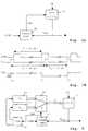
- FIG. 2illustrates a simplified diagram of a PLL according to an embodiment of the present invention allowing this modification of the long and short periods of the signal Fint by adequate modifications of the division numbers N H and N L of FIG. 1A.
- This PLLcomprises a digital phase comparator 10, identical to that used in the conventional PLL of FIG. 1A, receiving the SYNC and Fint signals and delivering the signal SGN.
- the signal Fintis obtained by dividing a clock signal CK through a programmable N divider (DIV N) 13.
- the divider 13includes a programming input on which the number N is presented. This number N is supplied by a multiplexer 14 with two inputs.
- the state “1" of the signal SGNselects the first input of the multiplexer 14 on which is presented the high number N H stored in a memory 16.
- the state “0" of the signal SGNselects the second input of the multiplexer on which is presented the low number N L stored in a memory 17.
- the elements of the PLL according to the invention described abovehave the same functions as those of the conventional PLL of FIG. 1A and have the same aim of generating a signal Fint with short periods T L and long periods T H succeeding each other in such a way that the average period of the signal Fint taken over a large number of periods is equal to the period T of the signal SYNC.
- the divider by N H or by conventional N L 12has been replaced by the programmable divider 13 to which one of the numbers N H and N L is supplied from the outside by means of the multiplexer 14 switched by the SGN signal.
- the periods T H and T Lare modified in the manner previously described.
- a method of modifying the numbers N H and N L according to a particular embodiment of the present inventionwill be described in more detail below.
- the low number N Lwould be incremented very slowly.
- the high number N Hwill be incremented for each period subsequent to the period in which 4 "1" successive have been detected in the analysis window. This causes rapid centering of the period T between the long periods T H and short T L. Indeed, one then obtains a modification of one or the other of the numbers N H and N L at all the periods except the 4 periods at "1" succeeding a "0" of the signal SGN.
- the period Tis centered, we find our in case a) above where convergence is rapid.
- FIG. 3illustrates a detailed embodiment of the PLL of Figure 2.
- the memories 16 and 17 containing the numbers high N H and low N Lare up / down counters clocked by the signal Fint coming from the programmable program divider 13.
- the other elements described belowconstitute the control circuit 18 of FIG. 2.
- the last three states SGN -1 , SGN -2 and SGN -3 of the output signal SGN of the phase comparator 10are stored in three flip-flops 34 of a shift register 35, SGN 0 the state of the current SGN signal.
- the shift register 35is clocked by the signal Fint and constitutes the previously mentioned analysis window.
- the states SGN 0 to SGN -3are respectively applied to the inputs of an AND gate 37 with four inputs, the output of which is connected via an AND gate 38 with two inputs to the count validation input ( UP) of the up / down counter 16.
- Complements of states SGN 0 to SGN -3are applied respectively to the inputs of an AND gate 40 with four inputs, the output of which is connected via an AND gate 41 with two inputs to the validation input of DOWN / DOWN COUNTER UPDATE 17.
- the complement of the state SGN 0 , the state SGN -1 , and the complement of the state SGN -2are respectively applied to the inputs of an AND gate 43 with three inputs, the output of which is connected via an AND 44 gate with two inputs to the down countdown validation input (DOWN) of up / down counter 16.
- the state SGN 0 , the complement of the state SGN -1 , and the state SGN -2are respectively applied to the inputs of an AND gate 46 with three inputs, the output of which is connected via a AND gate 47 with two inputs to the input for validation of counting by increments (UP) of up / down counter 17.
- the circuit according to the present inventioncomprises additional elements among which the AND gates 38, 41, 44 and 47 have been cited, making it possible to prevent the numbers N H > Nmax and N L from taking erroneous values, namely N H > Nmax, N L ⁇ Nmin, and N H ⁇ N L.
- the numbers Nmax and Nminrespectively designate the numbers corresponding to the extreme periods of the signal Fint, between which is supposed to fluctuate the period of the signal SYNC.
- N Hits output
- UPvalidation of counting
- the counter output (N L )is connected to a comparator 52 which compares the number N L to Nmin and inhibits the countdown validation (DOWN) of the counter 17 by presenting a state "0" on the second input of the AND gate 41 when N L ⁇ Nmin.
- N H and N Lare also compared in a comparator 54 which inhibits the input for validation of counting by decrements (DOWN) of counter 16 and the validation of counting by increments (UP) of counter 17 by presenting a "0" on the second inputs of AND gates 44 and 47 when N H ⁇ N L.
- N H and N Lare numbers remaining close to a large number, of the order of 7000 in a practical example which will be described below. Storing large numbers that are not very variable in counters 16 and 17 is not advantageous since it would require counters with a large number of bits. We prefer to store in the counters 16 and 17 intermediate numbers top n H and bottom n L between 0 and a number codable on an acceptable number of bits, these numbers then being supplied to a particular programmable divider which calculates from these numbers the appropriate division factor N.
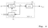
- FIG. 4illustrates a different, equivalent embodiment of the programable divider and is intended to show that the present invention is capable of numerous variant embodiments.
- the programmable divider of FIG. 4comprises a divider by 9 or by 10 (DIV 9/10) 60 receiving as input the clock signal CK and delivering an intermediate signal Fi. Dividing by 9 (i.e. providing one pulse every nine pulses of the clock signal CK) or by 10 (i.e. providing one pulse every ten pulses signal CK) is selected by a 10/9 * signal. The state “1" of this signal causes the division by 10 and the state "0" causes the division by 9.
- the signal Fintis obtained from the intermediate signal Fi by dividing the latter by a divider 62.
- the 10/9 * signalis provided by a programmable pulse generator (n-PLS) 64 receiving as input the intermediate signal Fi and programmed by a number n which is one of the intermediate numbers n H and n L previously mentioned provided by the multiplexer 14 ( Figures 2 and 3). Each time a predetermined number (greater than n) of pulses of the input signal Fi has occurred, the pulse generator 64 will have transmitted only n at its output.
- n-PLSprogrammable pulse generator
- the clock signal CKhas a frequency of 111 MHz
- the divider 62is a divider by 768
- the pulse generator 64is a generator of n pulses among 1024 pulses of the signal Fi, the number n supplied by counters 16 or 17 being a binary number between 0 and 511 (coded on 9 bits).
- the signal Fihas successions of 1024 pulses of which n are separated from each other by 10 periods of the clock signal CK and of which 1024-n are separated from each other by 9 periods of the CK signal.
- the Fint signalhas one pulse every 768 pulses of the Fi signal.
- this circuitis a digital PLL which can be used in place of any PLL by adapting the frequency of the clock CK, the division rates of the divisors and the differences between the numbers N H and N L.
- counters, logic gates and dividerscan be made by properly programming a microprocessor and the shift register 35 can be replaced by memory cells.
Landscapes
- Stabilization Of Oscillater, Synchronisation, Frequency Synthesizers (AREA)
Description
Translated fromFrenchLa présente invention concerne les boucles à verrouillage de phase et en particulier une boucle à verrouillage de phase numérique.The present invention relates to phase locked loops and in particular a digital phase locked loop.
Une boucle à verrouillage de phase, couramment appelée PLL (du terme anglo-saxon " Phase Locked Loop") est un dispositif délivrant un signal synchronisé sur un signal de référence, c'est-à-dire ayant même phase et fréquence que le signal de référence. En l'absence du signal de référence, le PLL délivre un signal de fréquence approximativement égale à la fréquence nominale du signal de référence, le but du PLL étant de suivre le signal de référence et de fournir un signal semblable au signal de référence en cas d'absence accidentelle de ce dernier.A phase locked loop, commonly called PLL (from the English term "Phase Locked Loop") is a device delivering a signal synchronized to a reference signal, that is to say having the same phase and frequency as the signal reference. In the absence of the reference signal, the PLL delivers a signal of frequency approximately equal to the nominal frequency of the reference signal, the aim of the PLL being to follow the reference signal and to provide a signal similar to the reference signal in the event accidental absence of the latter.
La figure 1A illustre un schéma classique de PLL numérique simple, destiné à synchroniser les impulsions d'un signal interne Fint sur les impulsions d'un signal de référence SYNC. Ce PLL comprend un comparateur de phase numérique (PHASE-COMP) 10 recevant les signaux Fint et SYNC et délivrant à sa sortie un signal SGN. Le signal SGN prend un premier état logique (1) si le signal Fint est en avance de phase par rapport au signal SYNC, c'est-à-dire si une impulsion du signal Fint survient avant une impulsion du signal SYNC, et prend un deuxième état (0) si le signal Fint est en retard de phase. Le signal Fint est obtenu par division d'un signal d'horloge CK à travers un diviseur (DIV NH-NL) 12 piloté par le signal SGN du comparateur de phase. Le diviseur 12 divise le signal CK par un nombre haut fixe NH lorsque le signal SGN est à "1" et par un nombre bas fixe NL lorsque le signal SGN est à "0".FIG. 1A illustrates a conventional diagram of a simple digital PLL, intended to synchronize the pulses of an internal signal Fint with the pulses of a reference signal SYNC. This PLL comprises a digital phase comparator (PHASE-COMP) 10 receiving the signals Fint and SYNC and delivering at its output a signal SGN. The signal SGN takes a first logic state (1) if the signal Fint is in phase advance with respect to the signal SYNC, i.e. if a pulse of the signal Fint occurs before a pulse of the signal SYNC, and takes a second state (0) if the signal Fint is delayed in phase. The signal Fint is obtained by dividing a clock signal CK through a divider (DIV NH -NL ) 12 controlled by the signal SGN of the phase comparator. The
Le nombre NH est tel que le signal Fint obtenu par division du signal d'horloge CK par ce nombre NH ait une période supérieure à la période nominale du signal de référence SYNC. Le nombre NL est tel que le signal Fint ait une période inférieure à la période nominale du signal de référence SYNC.The number NH is such that the signal Fint obtained by dividing the clock signal CK by this number NH has a period greater than the nominal period of the reference signal SYNC. The number NL is such that the signal Fint has a period less than the nominal period of the reference signal SYNC.
La figure 1B illustre les signaux SYNC, Fint et SGN dans un exemple d'application du PLL de la figure 1A à des signaux de télévision où le signal Fint est utilisé pour générer le balayage horizontal d'écran. Le signal SYNC provient alors d'un circuit de réception ou d'un magnétoscope et sa période nominale est de 64 microsecondes.Figure 1B illustrates the SYNC, Fint and SGN signals in an example of applying the PLL of Figure 1A to television signals where the Fint signal is used to generate horizontal screen scanning. The SYNC signal then comes from a reception circuit or a video recorder and its nominal period is 64 microseconds.
La période T du signal SYNC, notamment dans le cas d'un magnétoscope où elle est déterminée par la vitesse de défilement de la bande, peut fluctuer dans une plage assez importante. Le nombre NH est choisi pour que le signal Fint correspondant ait une période longue TH supérieure à la période maximale du signal SYNC, par exemple 65 microsecondes. Le nombre NL est choisi pour que le signal Fint correspondant ait une période courte TL inférieure à la période minimale, par exemple 63 microsecondes.The period T of the SYNC signal, in particular in the case of a video recorder where it is determined by the tape speed, can fluctuate within a fairly large range. The number NH is chosen so that the corresponding signal Fint has a long period TH greater than the maximum period of the signal SYNC, for example 65 microseconds. The number NL is chosen so that the corresponding signal Fint has a short period TL less than the minimum period, for example 63 microseconds.
La figure 1B illustre les signaux obtenus en régime établi en supposant que le signal SYNC est à sa période nominale de 64 microsecondes.FIG. 1B illustrates the signals obtained in steady state assuming that the SYNC signal is at its nominal period of 64 microseconds.
A un instant t0, une impulsion du signal Fint est détectée avant une impulsion de synchronisation du signal SYNC, ce qui indique que le signal Fint est en avance de phase par rapport au signal SYNC. Le signal SGN du comparateur de phase passe à l'état "1" et sélectionne la division du signal d'horloge CK par le nombre haut NH. La période suivante du signal Fint est donc fixée à 65 microsecondes.At a time t0, a pulse of the signal Fint is detected before a synchronization pulse of the signal SYNC, which indicates that the signal Fint is in phase advance compared to the signal SYNC. The SGN signal of the phase comparator goes to state "1" and selects the division of the clock signal CK by the high number NH. The next period of the signal Fint is therefore fixed at 65 microseconds.
A un instant t1, on détecte l'impulsion de synchronisation suivante du signal SYNC avant une impulsion du signal Fint. Ceci indique que le signal Fint est en retard de phase par rapport au signal SYNC. Le signal SGN passe à l'état "0" et sélectionne la division par le nombre bas NL et donc une période du signal Fint de 63 microsecondes.At an instant t1, the next synchronization pulse of the SYNC signal is detected before a pulse of the signal Fint. This indicates that the Fint signal is lagging behind the SYNC signal. The signal SGN goes to state "0" and selects the division by the low number NL and therefore a period of the signal Fint of 63 microseconds.
A un instant t2, une impulsion du signal Fint est détectée avant l'impulsion de synchronisation suivante du signal SYNC, indiquant un retard de phase. Le signal SGN bascule à l'état "1" et le processus se répète comme à l'instant t0.At an instant t2, a pulse of the signal Fint is detected before the next synchronization pulse of the signal SYNC, indicating a phase delay. The signal SGN switches to state "1" and the process is repeated as at time t0.
Dans le cas ci-dessus où la période T du signal de référence SYNC est constante et égale à la moyenne des périodes longue et courte du signal Fint, la période du signal Fint oscille à chaque période entre 63 et 65 microsecondes.In the above case where the period T of the reference signal SYNC is constant and equal to the average of the long and short periods of the signal Fint, the period of the signal Fint oscillates in each period between 63 and 65 microseconds.
Si la période T est légèrement supérieure à 64 microsecondes, la période du signal Fint oscille de la même façon avec toutefois, de temps en temps, quelques périodes successives de 65 microsecondes. Si la période T est légèrement inférieure à 65 microsecondes, le signal Fint aura une période de 65 microsecondes avec de temps en temps une période de 63 microsecondes. En fait, les périodes longues ou courtes du signal Fint se succèdent de manière que la fréquence moyenne prise sur un grand nombre de périodes du signal Fint soit égale à celle du signal SYNC. On peut montrer que le rapport cyclique du signal SGN s'exprime par (T-TL)/(TH-TL).If the period T is slightly greater than 64 microseconds, the period of the signal Fint oscillates in the same way with, however, from time to time, a few successive periods of 65 microseconds. If the period T is slightly less than 65 microseconds, the signal Fint will have a period of 65 microseconds with from time to time a period of 63 microseconds. In fact, the long or short periods of the Fint signal succeed each other so that the average frequency taken over a large number of periods of the Fint signal is equal to that of the SYNC signal. It can be shown that the duty cycle of the signal SGN is expressed by (TTL ) / (TH -TL ).
Si la période T est supérieure à 65 microsecondes, la période du signal Fint se bloque à 65 microsecondes et est donc erronée.If the period T is greater than 65 microseconds, the period of the signal Fint is blocked at 65 microseconds and is therefore erroneous.
Les cas complémentaires se produisent lorsque la période T est comprise entre 63 et 64 microsecondes.Complementary cases occur when the period T is between 63 and 64 microseconds.
Ainsi, ce PLL est capable de suivre un signal de référence SYNC seulement si sa période T est comprise entre des limites déterminées (ici 63 et 65 microsecondes). On a donc intérêt à écarter le plus possible les périodes extrêmes du signal Fint pour agrandir la plage de poursuite.Thus, this PLL is able to follow a SYNC reference signal only if its period T is between determined limits (here 63 and 65 microseconds). It is therefore advantageous to remove as far as possible the extreme periods of the signal Fint in order to enlarge the tracking range.
Toutefois, en augmentant cet écart, on diminue la résolution du PLL. En effet, en supposant que le signal SYNC est le signal de synchronisation de balayage horizontal d'un téléviseur, les sauts de période entre les périodes extrêmes du signal Fint, à partir duquel le balayage est généré, se traduisent par des lignes sur l'écran débutant alternativement en avance ou en retard l'une par rapport à l'autre. Si les périodes extrêmes du signal Fint sont trop grandes, ces décalages de ligne deviennent gênants car visibles à l'oeil nu (une verticale se met à ressembler à des créneaux).However, increasing this deviation decreases the resolution of the PLL. Indeed, assuming that the SYNC signal is the horizontal scan synchronization signal of a television, the period jumps between the extreme periods of the Fint signal, from which the scan is generated, are reflected by lines on the screen starting alternately in advance or behind each other. If the extreme periods of the signal Fint are too large, these line offsets become troublesome because they are visible to the naked eye (a vertical begins to resemble slots).
Un objet de la présente invention est de prévoir un PLL numérique simple ayant une grande plage de poursuite et une bonne résolution.An object of the present invention is to provide a simple digital PLL having a large tracking range and good resolution.
Cet objet est atteint grâce à un procédé de synchronisation d'un signal prédéterminé sur un signal de référence ayant une période de référence, le signal prédéterminé ayant une période longue ou une période courte entre lesquelles est normalement comprise la période de référence, comprenant les étapes suivantes :
- a) analyser la durée de la période de référence par rapport aux durées des périodes longue et courte ;
- b) si la période de référence est plus proche de la période longue que de la période courte, incrémenter la période courte ;
- c) si la période de référence est plus proche de la période courte que de la période longue, décrémenter la période longue ;
- d) si la période de référence est supérieure à la période longue, incrémenter la période longue ; et
- e) si la période de référence est inférieure à la période courte, décrémenter la période courte.
- a) analyze the length of the reference period in relation to the lengths of the long and short periods;
- b) if the reference period is closer to the long period than to the short period, increment the short period;
- c) if the reference period is closer to the short period than to the long period, decrement the long period;
- d) if the reference period is greater than the long period, increment the long period; and
- e) if the reference period is less than the short period, decrement the short period.
Selon un mode de réalisation de la présente invention, l'étape a) consiste à analyser un nombre prédéterminé des dernières différences de phase successives entre le signal prédéterminé et le signal de référence et les conditions des étapes b) à e) sont réalisées respectivement si, parmi les dernières différences de phase :
- le nombre d'avances de phase est plus élevé que le nombre de retards de phase ;
- le nombre de retards de phase est plus élevé que le nombre d'avances de phase ;
- il n'y a pas de retards de phase ; et
- il n'y a pas d'avances de phase.
- the number of phase advances is higher than the number of phase delays;
- the number of phase delays is higher than the number of phase advances;
- there are no phase delays; and
- there are no phase advances.
Selon un mode de réalisation de la présente invention, il est prévu que, si le nombre d'avances de phase successives est supérieur à un nombre prédéterminé, on incrémente la période longue ; et, si le nombre de retards de phase successifs est supérieur au nombre prédéterminé, on décrémente la période courte.According to an embodiment of the present invention, it is provided that, if the number of successive phase advances is greater than a predetermined number, the long period is incremented; and, if the number of successive phase delays is greater than the predetermined number, the short period is decremented.
Selon un mode de réalisation de la présente invention, il est prévu les étapes consistant à comparer les périodes longue et courte et à inhiber la décrémentation de la période longue et l'incrémentation de la période courte quand la différence entre ces périodes est inférieure à un seuil prédéterminé.According to an embodiment of the present invention, the steps are provided consisting in comparing the long and short periods and in inhibiting the decrementation of the long period and the incrementation of the short period when the difference between these periods is less than one predetermined threshold.
Selon un mode de réalisation de la présente invention, il est prévu les étapes consistant à comparer la période longue à une période maximale et inhiber l'incrémentation de la période longue si ces périodes sont égales ; et comparer la période courte à une période minimale et inhiber la décrémentation de la période courte si ces périodes sont égales.According to an embodiment of the present invention, there are provided the steps consisting in comparing the long period with a maximum period and inhibiting the incrementation of the long period if these periods are equal; and compare the short period to a minimum period and inhibit the decrementing of the short period if these periods are equal.
La présente invention prévoit aussi un dispositif de synchronisation d'un signal interne sur un signal de référence, ces signaux comprenant chacun des impulsions se produisant normalement à une fréquence nominale, comprenant un comparateur de phase délivrant un signal de comparaison de phase à un état logique prédéterminé si la phase du signal interne est en avance par rapport à celle du signal de synchronisation, et à un état logique complémentaire dans le cas contraire ; un diviseur de fréquence programmable alimenté par une horloge et délivrant le signal interne ; un multiplexeur fournissant au diviseur pour le programmer un nombre binaire haut si ledit signal de comparaison est à un état prédéterminé, et un nombre binaire bas dans le cas contraire ; des moyens pour mémoriser séquentiellement les derniers états du signal de comparaison ; des premiers moyens de comptage/décomptage cadencés par le signal interne et fournissant ledit nombre binaire haut au multiplexeur ; des premiers moyens de détection mettant les premiers moyens de comptage/décomptage en position de décomptage lorsque les derniers états mémorisés du signal de comparaison présentent un seul état à l'état prédéterminé ; des deuxièmes moyens de comptage/décomptage cadencés par le signal interne et fournissant ledit nombre binaire bas au multiplexeur ; et des deuxièmes moyens de détection mettant les deuxièmes moyens de comptage/décomptage en position de comptage lorsque les derniers états mémorisés du signal de comparaison présentent un seul état à l'état complémentaire.The present invention also provides a device for synchronizing an internal signal to a reference signal, these signals each comprising pulses normally occurring at a nominal frequency, comprising a comparator phase delivering a phase comparison signal to a predetermined logic state if the phase of the internal signal is ahead of that of the synchronization signal, and to a complementary logic state otherwise; a programmable frequency divider powered by a clock and delivering the internal signal; a multiplexer providing the divider for programming a high binary number if said comparison signal is at a predetermined state, and a low binary number otherwise; means for sequentially storing the last states of the comparison signal; first up / down counting means clocked by the internal signal and supplying said high binary number to the multiplexer; first detection means placing the first up / down counting means in the down counting position when the last stored states of the comparison signal have a single state in the predetermined state; second up / down counting means clocked by the internal signal and supplying said low binary number to the multiplexer; and second detection means placing the second up / down counting means in the counting position when the last stored states of the comparison signal have a single state in the complementary state.
Selon un mode de réalisation de la présente invention, ce dispositif comprend en outre des troisièmes moyens de détection mettant les premiers moyens de comptage/décomptage position de comptage lorsque les états mémorisés du signal de comparaison sont tous à l'état prédéterminé ; et des quatrièmes moyens de détection mettant les deuxièmes moyens de comptage/décomptage en position de décomptage lorsque les états mémorisés du signal de comparaison sont tous à l'état complémentaire.According to an embodiment of the present invention, this device further comprises third detection means putting the first counting / down counting means counting position when the stored states of the comparison signal are all in the predetermined state; and fourth detection means placing the second up / down counting means in the down counting position when the stored states of the comparison signal are all in the complementary state.
Selon un mode de réalisation de la présente invention, ce dispositif comprend en outre un premier comparateur des nombres binaires haut et bas et mettant les premiers et deuxièmes moyens de comptage/décomptage en position de repos si le nombre haut est inférieur ou égal au nombre bas.According to an embodiment of the present invention, this device further comprises a first comparator of the high and low binary numbers and putting the first and second up / down counting means in the rest position if the high number is less than or equal to the low number .
Selon un mode de réalisation de la présente invention, ce dispositif comprend en outre un deuxième comparateur du nombre binaire haut à un nombre binaire maximum et mettant les premiers moyens de comptage/décomptage à la position de repos en cas de dépassement ; et un troisième comparateur du nombre binaire bas à un nombre minimum et mettant les deuxièmes moyens de comptage/décomptage à la position de repos en cas de dépassement.According to an embodiment of the present invention, this device further comprises a second comparator from the high binary number to a maximum binary number and putting the first up / down counting means in the rest position in the event of being exceeded; and a third comparator of the low binary number to a minimum number and putting the second up / down counting means in the rest position in the event of being exceeded.
Selon un mode de réalisation de la présente invention, le diviseur programmable comprend un diviseur par deux nombres distincts dont l'un ou l'autre est sélectionné par le signal de sortie d'un générateur d'impulsions programmé par le nombre fourni par le multiplexeur.According to an embodiment of the present invention, the programmable divider comprises a divider by two distinct numbers, one or the other of which is selected by the output signal of a pulse generator programmed by the number supplied by the multiplexer .
Ces objets, caractéristiques et avantages de la présente invention ainsi que d'autres seront exposés plus en détail dans la description suivante de modes de réalisation particuliers faite en relation avec les dessins joints parmi lesquels :
- les figures 1A et 1B, précédemment décrites, représentent respectivement un PLL numérique classique et des signaux relatifs à ce PLL ;
- La figure 2 représente un schéma simplifié d'un PLL numérique selon la présente invention ;
- la figure 3 illustre un exemple de réalisation détaillé du PLL de la figure 2 ; et
- la figure 4 illustre un mode de réalisation d'un diviseur programmable utilisable dans le PLL des figures 2
et 3.
- FIGS. 1A and 1B, previously described, respectively represent a conventional digital PLL and signals relating to this PLL;
- FIG. 2 represents a simplified diagram of a digital PLL according to the present invention;
- Figure 3 illustrates a detailed embodiment of the PLL of Figure 2; and
- FIG. 4 illustrates an embodiment of a programmable divider usable in the PLL of FIGS. 2 and 3.
Dans un système de synchronisation à boucle à verrouillage de phase du type de celui de la figure 1A, le procédé selon la présente invention consiste à modifier les périodes longue TH et courte TL du signal Fint de manière à les rapprocher le plus possible d'une période en cours T stable du signal SYNC en veillant à ce que cette dernière soit encadrée par les périodes longue et courte. Cela est effectué de la manière suivante.In a phase-locked loop synchronization system of the type of that of FIG. 1A, the method according to the present invention consists in modifying the long periods TH and short TL of the signal Fint so as to bring them as close as possible to d a stable period T of the SYNC signal while ensuring that the latter is framed by the long and short periods. This is done as follows.
A la suite d'un glissement de la fréquence du signal SYNC, la période T de ce dernier ne se trouve plus entre les périodes longue et courte du signal Fint. Si elle est, par exemple, supérieure à la période longue, cette période longue est incrémentée jusqu'à ce qu'elle redevienne supérieure à la période T. Si la période T est inférieure à la période courte, cette période courte est décrémentée jusqu'à ce qu'elle redevienne inférieure à la période T. Ensuite, on rapproche la période du signal Fint la plus éloignée de la période T jusqu'à ce que l'autre période du signal Fint se trouve être la plus éloignée, et ainsi de suite jusqu'à ce que les périodes longue et courte soient distantes l'une de l'autre d'une valeur minimum déterminée tout en encadrant la période T.Following a shift in the frequency of the SYNC signal, the period T of the latter is no longer between the long and short periods of the signal Fint. If it is, for example, greater than the long period, this long period is incremented until it becomes again greater than the period T. If the period T is less than the short period, this short period is decremented until to become less than period T. Next, the period farthest from the signal Fint is brought closer to period T until the other period of the signal Fint is found to be the farthest, and so continued until the long and short periods are distant from each other by a determined minimum value while framing the period T.
La figure 2 illustre un schéma simplifié d'un PLL selon un mode de réalisation de la présente invention permettant cette modification des périodes longues et courtes du signal Fint par des modifications adéquates des nombres de division NH et NL de la figure 1A. Ce PLL comprend un comparateur de phase numérique 10, identique à celui utilisé dans le PLL classique de la figure 1A, recevant les signaux SYNC et Fint et délivrant le signal SGN. Le signal Fint est obtenu par division d'un signal d'horloge CK à travers un diviseur par N programmable (DIV N) 13. Le diviseur 13 comprend une entrée de programmation sur laquelle est présenté le nombre N. Ce nombre N est fourni par un multiplexeur 14 à deux entrées. L'état "1" du signal SGN sélectionne la première entrée du multiplexeur 14 sur laquelle est présenté le nombre haut NH mémorisé dans une mémoire 16. L'état "0" du signal SGN sélectionne la deuxième entrée du multiplexeur sur laquelle est présenté le nombre bas NL mémorisé dans une mémoire 17.FIG. 2 illustrates a simplified diagram of a PLL according to an embodiment of the present invention allowing this modification of the long and short periods of the signal Fint by adequate modifications of the division numbers NH and NL of FIG. 1A. This PLL comprises a
Les éléments du PLL selon l'invention décrits ci-dessus ont les mêmes fonctions que ceux du PLL classique de la figure 1A et ont le même but de générer un signal Fint avec des périodes courtes TL et longues TH se succédant de telle manière que la période moyenne du signal Fint prise sur un grand nombre de périodes soit égale à la période T du signal SYNC.The elements of the PLL according to the invention described above have the same functions as those of the conventional PLL of FIG. 1A and have the same aim of generating a signal Fint with short periods TL and long periods TH succeeding each other in such a way that the average period of the signal Fint taken over a large number of periods is equal to the period T of the signal SYNC.
Le diviseur par NH ou par NL 12 classique a été remplacé par le diviseur programmable 13 auquel on fournit de l'extérieur l'un ou l'autre des nombres NH et NL par l'intermédiaire du multiplexeur 14 commuté par le signal SGN. Ainsi, en modifiant les nombres NH et NL on modifie les périodes TH et TL de la manière précédemment décrite. On va décrire plus en détail ci-après un procédé de modification des nombres NH et NL selon un mode de réalisation particulier de la présente invention.The divider by NH or by
Un circuit de commande (CTRL) 18 fait incrémenter ou décrémenter les nombres NH et NL dans les mémoires 16 et 17 en fonction de la succession des états du signal SGN. Le circuit 18 analyse les derniers états successifs du signal SGN dans une fenêtre d'un nombre prédéterminé de périodes, par exemple 4. L'interprétation des états du signal SGN permet de détecter les cas suivants et de provoquer des opérations correspondantes.
- a) Le signal SGN présente des états alternant entre "1" et "0" (son rapport cyclique est de 0,5). Comme cela a été mentionné en relation avec la figure 1B, la période T du signal SYNC est alors centrée entre les périodes courte TL et longue TH du signal Fint. Ces alternances du signal SGN sont détectées dans la fenêtre d'analyse et on décrémente le nombre haut NH une période sur deux en incrémentant le nombre bas NL lors de chacune des autres périodes. Ainsi, on obtient une convergence rapide des périodes longue TH et courte TL du signal Fint vers la période T du signal SYNC.
- b) Le signal SGN est continuellement à "1" (le signal Fint résultant est bloqué sur la période longue). Ceci indique que la période longue TH du signal Fint est inférieure à la période courante T du signal SYNC ou tout au moins insuffisante pour récupérer rapidement le retard de phase. Lorsque le signal SGN aura été pendant, par exemple, 4 périodes à "1" le nombre haut NH est incrémenté d'une unité à chacune des périodes ultérieures jusqu'à ce que le signal SGN soit détecté à "0".
- c) Le signal SGN présente des successions de "1" entrecoupées d'un " 0" de temps en temps (son rapport cyclique est proche de 1). Ceci indique que la période longue TH est supérieure à la période T mais plus proche de celle-ci que la période courte TL. A chaque fois que le "0" est détecté le nombre bas NL est incrémenté d'une unité pour rapprocher la période courte TL des périodes T et TH. Ainsi, le nombre de "1" successifs diminue de sorte que la période moyenne du signal résultant Fint reste égale à la période T, jusqu'au moment où l'on aura des "1" et des "0" alternés.
- a) The SGN signal has states alternating between "1" and "0" (its duty cycle is 0.5). As mentioned in connection with FIG. 1B, the period T of the signal SYNC is then centered between the short periods TL and long TH of the signal Fint. These alternations of the signal SGN are detected in the analysis window and the high number NH is decremented every other period by incrementing the low number NL during each of the other periods. Thus, one obtains a rapid convergence of the long periods TH and short TL of the signal Fint towards the period T of the signal SYNC.
- b) The SGN signal is continuously at "1" (the resulting Fint signal is blocked over the long period). This indicates that the long period TH of the signal Fint is less than the current period T of the signal SYNC or at least insufficient to quickly recover the phase delay. When the signal SGN has been for, for example, 4 periods at "1" the high number NH is incremented by one in each of the subsequent periods until the signal SGN is detected at "0".
- c) The SGN signal presents successions of "1" interspersed with a "0" from time to time (its duty cycle is close to 1). This indicates that the long period TH is greater than the period T but closer to it than the short period TL. Each time the "0" is detected, the low number NL is incremented by one to bring the short period TL closer to the periods T and TH. Thus, the number of successive "1" decreases so that the average period of the resulting signal Fint remains equal to the period T, until the moment when there will be alternating "1" and "0".
Toutefois, dans le cas où le nombre de "1" serait très important, le nombre bas NL serait incrémenté très lentement. Pour accélérer la convergence, on procède de préférence comme suit. Comme dans le cas b), le nombre haut NH sera incrémenté pour chaque période ultérieure à la période où l'on aura détecté 4 "1" successifs dans la fenêtre d'analyse. Ceci provoque un centrage rapide de la période T entre les périodes longue TH et courte TL. En effet, on obtient alors une modification de l'un ou l'autre des nombres NH et NL à toutes les périodes excepté les 4 périodes à "1" succédant un "0" du signal SGN. Lorsque la période T est centrée, on se trouve dans le cas a ) ci-dessus où la convergence est rapide.However, in the case where the number of "1" is very large, the low number NL would be incremented very slowly. To accelerate the convergence, one proceeds preferably as follows. As in case b), the high number NH will be incremented for each period subsequent to the period in which 4 "1" successive have been detected in the analysis window. This causes rapid centering of the period T between the long periods TH and short TL. Indeed, one then obtains a modification of one or the other of the numbers NH and NL at all the periods except the 4 periods at "1" succeeding a "0" of the signal SGN. When the period T is centered, we find ourselves in case a) above where convergence is rapid.
Les cas d) et e) ci-dessous correspondent aux cas complémentaires des cas b) et c) et les mêmes raisonnements sont valables.
- d) Le signal SGN est continuellement à "0". Ceci indique que la période courte TL est supérieure à la période T. Lorsque le signal SGN aura été pendant 4 périodes à "0" le nombre bas NL est décrémenté d'une unité à chacune des périodes ultérieures, jusqu'à ce que le signal SGN soit détecté à "1".
- e) Le signal SGN présente des successions de "0" entrecoupées d'un "1" de temps en temps (son rapport cyclique est proche de 0). Ceci indique que la période courte TL est inférieure à la période T mais plus proche de celle-ci que la période longue TH. A chaque fois que le "1" est détecté le nombre haut NH est décrémenté d'une unité. Le nombre bas NL est incrémenté pour chaque période ultérieure à la période où l'on aura détecté 4 "0" successifs dans la fenêtre d'analyse, jusqu'au moment où l'on aura des "1" et des "0" alternés.
- d) The SGN signal is continuously "0". This indicates that the short period TL is greater than the period T. When the signal SGN has been for 4 periods at "0" the low number NL is decremented by one unit in each of the subsequent periods, until the SGN signal is detected at "1".
- e) The signal SGN presents successions of "0" interspersed with a "1" from time to time (its duty cycle is close to 0). This indicates that the short period TL is less than the period T but closer to it than the long period TH. Each time the "1" is detected, the high number NH is decremented by one. The low number NL is incremented for each period subsequent to the period in which 4 "0" successive are detected in the analysis window, until the moment when there are "1" and "0" alternated.
Bien entendu, le PLL selon l'invention fonctionne pourvu que certaines conditions soient respectées. Notamment, on doit avoir NH>NL et il faut par conséquent éviter de décrémenter le nombre NH ou d'incrémenter le nombre NL lorsqu'ils ne diffèrent que d'une unité à l'étape a). On verra en relation avec la figure 3 comment ces conditions sont respectées.Of course, the PLL according to the invention works provided that certain conditions are met. In particular, we must have NH > NL and we must therefore avoid decreasing the number NH or incrementing the number NL when they differ only by one in step a). We will see in relation to Figure 3 how these conditions are met.
La figure 3 illustre un mode de réalisation détaillé du PLL de la figure 2. On retrouve le comparateur de phase 10, le multiplexeur 14 et le diviseur programmable 13 de la figure 2. Les mémoires 16 et 17 contenant les nombres haut NH et bas NL sont des compteurs/décompteurs cadencés par le signal Fint provenant du diviseur programmer ble 13. Les autres éléments décrits ci-après constituent le circuit de commande 18 de la figure 2.Figure 3 illustrates a detailed embodiment of the PLL of Figure 2. We find the
Les trois derniers états SGN-1, SGN-2 et SGN-3 du signal de sortie SGN du comparateur de phase 10 sont stockés dans trois bascules 34 d'un registre à décalage 35, SGN0 l'état du signal SGN courant. Le registre à décalage 35 est cadencé par le signal Fint et constitue la fenêtre d'analyse précédemment mentionnée.The last three states SGN-1 , SGN-2 and SGN-3 of the output signal SGN of the
Les états SGN0 à SGN-3 sont respectivement appliqués aux entrées d'une porte ET 37 à quatre entrées, dont la sortie est reliée par l'intermédiaire d'une porte ET 38 à deux entrées à l'entrée de validation de comptage (UP) du compteur/décompteur 16.The states SGN0 to SGN-3 are respectively applied to the inputs of an AND
Les complémentaires des états SGN0 à SGN-3 sont appliqués respectivement aux entrées d'une porte ET 40 à quatre entrées, dont la sortie est reliée par l'intermédiaire d'une porte ET 41 à deux entrées à l'entrée de validation de décomptage (DOWN) du compteur/décompteur 17.Complements of states SGN0 to SGN-3 are applied respectively to the inputs of an AND
Le complémentaire de l'état SGN0, l'état SGN-1, et le complémentaire de l'état SGN-2 sont respectivement appliqués aux entrées d'une porte ET 43 à trois entrées, dont la sortie est reliée par l'intermédiaire d'une porte ET 44 à deux entrées à l'entrée de validation de décomptage (DOWN) du compteur/décompteur 16.The complement of the state SGN0 , the state SGN-1 , and the complement of the state SGN-2 are respectively applied to the inputs of an AND
L'état SGN0, le complémentaire de l'état SGN-1, et l'état SGN-2 sont respectivement appliqués aux entrées d'une porte ET 46 à trois entrées, dont la sortie est reliée par l'intermédiaire d'une porte ET 47 à deux entrées à l'entrée de validation de comptage par incréments (UP) du compteur/décompteur 17.The state SGN0 , the complement of the state SGN-1 , and the state SGN-2 are respectively applied to the inputs of an AND
Dans un premier temps, on ne tiendra pas compte des portes ET 38, 41, 44 et 47 et d'autres éléments non encore décrits du circuit car ils n'influent pas sur le fonctionnement principal du PLL. On suppose que les sorties des portes ET 37, 40, 43 et 46 sont directement reliées aux entrées de validation de comptage par incréments et décréments des compteurs/décompteurs 16 et 17 et que le nombre NH est supérieur au nombre NL. Le fonctionnement du PLL selon la présente invention est décrit ci-après en relation avec la figure 3.Initially, the AND
Quatre "1" consécutifs du signal SGN, ce qui correspond aux cas b) et c) précédemment mentionnés, sont détectés par la porte ET 37 qui valide le comptage du compteur 16 et donc l'incrémentation d'une unité du nombre NH à l'impulsion suivante du signal Fint.Four consecutive "1" of the signal SGN, which corresponds to the cases b) and c) previously mentioned, are detected by the AND
Quatre "0" consécutifs du signal SGN, ce qui correspond aux cas d) et e) précédemment mentionnés, sont détectés par la porte ET 40 qui valide le décomptage du compteur 17 et donc la décrémentation d'une unité du nombre NL à l'impulsion suivante du signal Fint.Four consecutive "0" of the signal SGN, which corresponds to the cases d) and e) previously mentioned, are detected by the AND
Une succession d'états 1, 0, 1 du signal SGN, ce qui correspond aux cas a) et c) précédemment mentionnés, est détectée par la porte 46 qui valide le comptage du compteur 17 et donc l'incrémentation du nombre NL à l'impulsion suivante du signal Fint.A succession of
Une succession d'états 0, 1, 0 du signal SGN, ce qui correspond aux cas a) et e) précédemment mentionnés, est détectée par la porte 43 qui valide le décomptage du compteur 16 et donc la décrémentation du nombre NH à l'impulsion suivante du signal Fint.A succession of
Le circuit selon la présente invention comprend des éléments additionnels parmi lesquels on a cité les portes ET 38, 41, 44 et 47, permettant d'éviter que les nombres NH>Nmax et NL prennent des valeurs erronées, à savoir NH>Nmax, NL<Nmin, et NH<NL. Les nombres Nmax et Nmin désignent respectivement les nombres correspondant aux périodes extrêmes du signal Fint, entre lesquelles est supposée fluctuer la période du signal SYNC.The circuit according to the present invention comprises additional elements among which the AND
Pour éviter que le compteur 16 compte au-delà de Nmax, sa sortie (NH) est reliée à un comparateur 50 qui compare le nombre NH à Nmax et inhibe la validation de comptage (UP) du compteur 16 en présentant un état "0" sur la deuxième entrée de la porte ET 38 lorsque NH>Nmax.To prevent the
Pour éviter que le compteur 17 décompte en-deçà de Nmin, la sortie (NL) du compteur est reliée à un comparateur 52 qui compare le nombre NL à Nmin et inhibe la validation de décomptage (DOWN) du compteur 17 en présentant un état "0" sur la deuxième entrée de la porte ET 41 lorsque NL<Nmin.To prevent the
Les nombres NH et NL sont également comparés dans un comparateur 54 qui inhibe l'entrée de validation de comptage par décréments (DOWN) du compteur 16 et la validation de comptage par incréments (UP) du compteur 17 en présentant un "0" sur les deuxièmes entrées des portes ET 44 et 47 lorsque NH<NL.The numbers NH and NL are also compared in a
Les nombres NH et NL sont des nombres restant voisins d'un nombre grand, de l'ordre de 7000 dans un exemple pratique que l'on décrira ci après. Stocker des nombres grands peu variables dans les compteurs 16 et 17 n'est pas avantageux car il faudrait des compteurs à grand nombre de bits. On préfère stocker dans les compteurs 16 et 17 des nombres intermédiaires haut nH et bas nL compris entre 0 et un nombre codable sur un nombre de bits acceptable, ces nombres étant ensuite fournis à un diviseur programmable particulier qui calcule à partir de ces nombres le facteur de division N adéquat.The numbers NH and NL are numbers remaining close to a large number, of the order of 7000 in a practical example which will be described below. Storing large numbers that are not very variable in
On pourrait simplement obtenir NH et NL en ajoutant à nH et nL un nombre constant.We could simply obtain NH and NL by adding a constant number to nH and nL.
La figure 4 illustre une réalisation différente, équivalente, du diviseur programmer ble et est destinée à montrer que la présente invention est susceptible de nombreuses variantes de réalisation. Le diviseur programmable de la figure 4 comprend un diviseur par 9 ou par 10 (DIV 9/10) 60 recevant en entrée le signal d'horloge CK et délivrant un signal intermediaire Fi. La division par 9 ( c'est-à-dire la fourniture d'une impulsion toutes les neuf impulsions du signal d'horloge CK) ou par 10 (c'est-à-dire la fourniture d'une impulsion toutes les dix impulsions du signal CK) est sélectionnée par un signal 10/9*. L'état "1" de ce signal provoque la division par 10 et l'état "0" provoque la division par 9. Le signal Fint est obtenu à partir du signal intermédiaire Fi en divisant ce dernier par un diviseur 62.FIG. 4 illustrates a different, equivalent embodiment of the programable divider and is intended to show that the present invention is capable of numerous variant embodiments. The programmable divider of FIG. 4 comprises a divider by 9 or by 10 (
Le signal 10/9* est fourni par un générateur d'impulsions programmable (n-PLS) 64 recevant en entrée le signal intermédiaire Fi et programmé par un nombre n qui est l'un des nombres intermédiaires nH et nL précédemment mentionnés fournis par le multiplexeur 14 (figures 2 et 3). Chaque fois qu'il se sera produit un nombre prédéterminé (supérieur à n) d'impulsions du signal d'entrée Fi, le générateur d'impulsions 64 n'en aura transmis sur sa sortie que n.The 10/9* signal is provided by a programmable pulse generator (n-PLS) 64 receiving as input the intermediate signal Fi and programmed by a number n which is one of the intermediate numbers nH and nL previously mentioned provided by the multiplexer 14 (Figures 2 and 3). Each time a predetermined number (greater than n) of pulses of the input signal Fi has occurred, the
Dans un exemple adapté à la télévision, le signal d'horloge CK a une fréquence de 111 MHz, le diviseur 62 est un diviseur par 768, et le générateur d'impulsions 64 est un générateur de n impulsions parmi 1024 impulsions du signal Fi, le nombre n fourni par les compteurs 16 ou 17 étant un nombre binaire compris entre 0 et 511 (codé sur 9 bits).In an example suitable for television, the clock signal CK has a frequency of 111 MHz, the
Avec cette configuration de diviseur, le signal Fi présente des successions de 1024 impulsions dont n sont écartées l'une de l'autre de 10 périodes du signal d'horloge CK et dont 1024-n sont écartées l'une de l'autre de 9 périodes du signal CK. Le signal Fint présente une impulsion toutes les 768 impulsions du signal Fi.With this divider configuration, the signal Fi has successions of 1024 pulses of which n are separated from each other by 10 periods of the clock signal CK and of which 1024-n are separated from each other by 9 periods of the CK signal. The Fint signal has one pulse every 768 pulses of the Fi signal.
Ainsi, la fréquence du signal Fint est égale à celle du signal d'horloge CK divisée par N = 768[(n/1024) + 9]. Si n=256, on a N=7104 et la fréquence du signal Fint est égale à la fréquence horizontale nominale de 15625 Hz.Thus, the frequency of the signal Fint is equal to that of the clock signal CK divided by N = 768 [(n / 1024) + 9]. If n = 256, we have N = 7104 and the frequency of the signal Fint is equal to the nominal horizontal frequency of 15625 Hz.
Lorsque ce diviseur est utilisé dans le PLL selon la présente invention, dès que les nombres intermédiaires haut nH et bas nL sont différents d'une unité, la différence entre la période longue et la période courte du signal Fint est de 6, 7 nanosecondes, ce qui correspond à un décalage imperceptible sur un écran de téléviseur.When this divider is used in the PLL according to the present invention, as soon as the intermediate numbers high nH and low nL are different from one unit, the difference between the long period and the short period of the signal Fint is 6, 7 nanoseconds, which is an imperceptible lag on a TV screen.
En outre, le PLL selon la présente invention peut suivre un signal SYNC ayant une période variable entre 62,3 et 65,7 microsecondes (correspondant respectivement à nL = 0 et nH = 511). Ces périodes extrêmes peuvent être écartées en prenant des compteurs/décompteurs et un diviseur programmable avec un plus grand nombre de bits, et en diminuant le facteur de division du diviseur 62. La différence minimum entre périodes courte et longue peut être réduite en prenant un signal d'horloge CK de fréquence supérieure et en augmentant le facteur de division du diviseur 62.In addition, the PLL according to the present invention can follow a SYNC signal having a variable period between 62.3 and 65.7 microseconds (corresponding respectively to nL = 0 and nH = 511). These extreme periods can be eliminated by taking up / down counters and a programmable divider with a larger number of bits, and by reducing the dividing factor of the
Dans le mode de réalisation décrit en relation avec la figure 3, on a choisi de détecter au bout de quatre périodes (portes ET 37, 40) une avance ou un retard de phase durable du signal Fint. L'apparition d'une phase différente occasionnelle est détectée sur trois périodes (portes ET 43, 46). On pourrait également choisir des détections sur trois périodes dans les deux cas.In the embodiment described in relation to FIG. 3, it has been chosen to detect at the end of four periods (AND
La présente invention a été décrite en relation avec des signaux de télévision, mais l'homme de l'art notera que ce circuit est un PLL numérique qui peut être utilisé à la place de tout PLL en adaptant la fréquence de l'horloge CK, les taux de division des diviseurs et les écarts entre les nombres NH et NL. De nombreuses variantes et modifications de la présente invention apparaîtront à l'homme de l'art, par exemple, les compteurs, les portes logiques et les diviseurs peuvent être réalisés en programmant convenablement un microprocesseur et le registre à décalage 35 peut être remplacé par des cases d'une mémoire. On peut envisager d'autres circuits logiques réalisant les mêmes fonctions que celles des circuits logiques décrits.The present invention has been described in relation to television signals, but those skilled in the art will note that this circuit is a digital PLL which can be used in place of any PLL by adapting the frequency of the clock CK, the division rates of the divisors and the differences between the numbers NH and NL. Many variants and modifications of the present invention will be apparent to those skilled in the art, for example, counters, logic gates and dividers can be made by properly programming a microprocessor and the
Claims (10)
- A method for synchronizing a predetermined signal (Fint) with respect to a reference signal (SYNC) having a reference period (T), said predetermined signal having a long period (TH) or a short period (TL) between which said reference period (T) is normally included, comprising the steps of:
a) analyzing the duration of said reference period (T) with respect to the duration of the long (TH) and short (TL) periods;
characterized in that it comprises the following steps:b) if the reference period (T) is closer to the long period (TH) than the short period (TL), incrementing the short period (TL);c) if the reference period (T) is closer to the short period (TL) than the long period (TH), decrementing the long period (TH);d) if the reference period (T) is higher than the long period (TH), incrementing the long period (TH); ande) if the reference period (T) is lower than the short period (TL), decrementing the short period (TL). - A method according to claim 1, characterized in that step a) consists in analyzing a predetermined number of the latest successive differences of phase between said predetermined signal (Fint) and said reference signal (SYNC) and wherein the requirements of steps b) to e) are met if, respectively, among the last phase differences:- the number of phases in advance is higher than the number of lagged phases;- the number of lagged phases is higher than the number of phases in advance;- there is no phase lag; and- there is no phase advance.
- A method according to claim 2, characterized in that it comprises the following steps:- if the number of successive phases in advance is higher than a predetermined number, incrementing the long period (TH); and- if the number of successive phase lags is higher than the predetermined number, decrementing the short period (TL).
- A method according to any of claims 1 to 3, characterized in that it comprises the following steps:- comparing the long and short (TH, TL) periods; and- inhibiting the decrementation of the long period and the incrementation of the short period when the difference between these periods is lower than a predetermined threshold.
- A method of any of claims 1 to 4, characterized in that it comprises the following steps:- comparing the long period (TH) with a maximum period and inhibiting the incrementation of the long period if said periods are equal; and- comparing the short period (TL) with a minimum period and inhibiting the decrementation of the short period if said periods are equal.
- A device for synchronizing an internal signal (Fint) with respect to a reference signal (SYNC), said signals each comprising pulses normally occurring at a rated frequency, comprising:- a phase comparator (10) providing a phase comparison signal (SGN) at a predetermined logic state if the phase of said internal signal (Fint) is in advance with respect to the phase of the synchronization signal (SYNC), and at a complementary logic state otherwise;- a programmable frequency divider (13) fed by a clock (CK) and providing said internal signal (Fint);characterized in that it comprises:- a multiplexer (14) providing to said divider (13), in order to program it, a high binary number (NH) if said comparison signal is at the predetermined state, and a low binary number (NL), otherwise;- means (34) for sequentially storing the latest states of the comparison signal (SGN);- first up-down counting means (16) clocked by said internal signal (Fint) and providing said high binary number (NH) to the multiplexer;- first detection means (43) setting the first up-down counting means (16) in down-counting position when the latest stored states of the comparison signal (SGN) have a single state at the predetermined state;- second up-down counting means (17), clocked by said internal signal (Fint) and providing said low binary number (NL) to said multiplexer (14); and- second detection means (46) setting said second up-down counting means (17) in up-counting position when the latest stored states of said comparison signal (SGN) have a single state at the complementary state.
- A device according to claim 6, characterized in that it comprises:- third detection means (37) setting the first up-down counting means (16) in up-counting position when all the stored states of said comparison signal are at the predetermined state; and- fourth detection means (40) setting the second up-down counting means (17) to down-counting position when all the stored states of said comparison signal are at the complementary state.
- A device according to claim 6 or 7, characterized in that it comprises a first comparator (54) for comparing the high and low binary numbers (NH, NL) and setting said first and second up-down counting means (16, 17) in standby state if the high number is lower than or equal to the low number.
- A device according to any of claims 6 to 8, characterized in that it comprises:- a second comparator (50) comparing said high binary number (NH) with a maximum binary number and setting said counting up-down means (16) in standby state if said number is exceeded; and- a third comparator (52) comparing said low binary number (NL) with a minimum number and setting said second up-down counting means (17) in standby state if said number is exceeded.
- A device according to any of claims 6 to 9, characterized in that said programmable divider (13) comprises a divider (60) by two distinct numbers, either one is selected by the output signal of a pulse generator (64) programmed by the number provided by the multiplexer (14).
Applications Claiming Priority (2)
| Application Number | Priority Date | Filing Date | Title |
|---|---|---|---|
| FR9109925 | 1991-07-30 | ||
| FR9109925AFR2680058B1 (en) | 1991-07-30 | 1991-07-30 | METHOD AND DEVICE FOR SYNCHRONIZING A SIGNAL. |
Publications (2)
| Publication Number | Publication Date |
|---|---|
| EP0526359A1 EP0526359A1 (en) | 1993-02-03 |
| EP0526359B1true EP0526359B1 (en) | 1996-09-25 |
Family
ID=9415924
Family Applications (1)
| Application Number | Title | Priority Date | Filing Date |
|---|---|---|---|
| EP92420253AExpired - LifetimeEP0526359B1 (en) | 1991-07-30 | 1992-07-27 | Process and circuit arrangement for synchronising a signal |
Country Status (5)
| Country | Link |
|---|---|
| US (2) | US5319681A (en) |
| EP (1) | EP0526359B1 (en) |
| JP (1) | JPH05243982A (en) |
| DE (1) | DE69214055T2 (en) |
| FR (1) | FR2680058B1 (en) |
Families Citing this family (7)
| Publication number | Priority date | Publication date | Assignee | Title |
|---|---|---|---|---|
| US5832048A (en)* | 1993-12-30 | 1998-11-03 | International Business Machines Corporation | Digital phase-lock loop control system |
| US5570066A (en)* | 1994-08-30 | 1996-10-29 | Motorola, Inc. | Method of programming a frequency synthesizer |
| US6310922B1 (en)* | 1995-12-12 | 2001-10-30 | Thomson Consumer Electronics, Inc. | Method and apparatus for generating variable rate synchronization signals |
| US5784332A (en)* | 1996-12-12 | 1998-07-21 | Micron Technology Corporation | Clock frequency detector for a synchronous memory device |
| US6172935B1 (en) | 1997-04-25 | 2001-01-09 | Micron Technology, Inc. | Synchronous dynamic random access memory device |
| US6628276B1 (en) | 2000-03-24 | 2003-09-30 | Stmicroelectronics, Inc. | System for high precision signal phase difference measurement |
| US6826247B1 (en) | 2000-03-24 | 2004-11-30 | Stmicroelectronics, Inc. | Digital phase lock loop |
Family Cites Families (12)
| Publication number | Priority date | Publication date | Assignee | Title |
|---|---|---|---|---|
| US3646452A (en)* | 1971-02-16 | 1972-02-29 | Ibm | Second order digital phaselock loop |
| DE2413604A1 (en)* | 1974-03-21 | 1975-09-25 | Blaupunkt Werke Gmbh | PHASE-LOCKED REGULAR LOOP |
| US4280099A (en)* | 1979-11-09 | 1981-07-21 | Sperry Corporation | Digital timing recovery system |
| US4400817A (en)* | 1980-12-30 | 1983-08-23 | Motorola, Inc. | Method and means of clock recovery in a received stream of digital data |
| EP0134374B1 (en)* | 1983-09-07 | 1987-12-02 | International Business Machines Corporation | Phase-locked clock |
| US4748644A (en)* | 1986-01-29 | 1988-05-31 | Digital Equipment Corporation | Method and apparatus for a constant frequency clock source in phase with a variable frequency system clock |
| JPH0744448B2 (en)* | 1986-03-31 | 1995-05-15 | 株式会社東芝 | Digital phase synchronization loop circuit |
| JPH0770991B2 (en)* | 1986-08-27 | 1995-07-31 | 日本電気株式会社 | Clock reproduction circuit |
| US4820993A (en)* | 1987-08-17 | 1989-04-11 | Cyclotomics, Inc. | Digital phase lock loop |
| US4870684A (en)* | 1987-11-16 | 1989-09-26 | Sanyo Electric Co., Ltd. | PLL circuit for generating output signal synchronized with input signal by switching frequency dividing ratio |
| US4890305A (en)* | 1988-02-12 | 1989-12-26 | Northern Telecom Limited | Dual-tracking phase-locked loop |
| US5077529A (en)* | 1989-07-19 | 1991-12-31 | Level One Communications, Inc. | Wide bandwidth digital phase locked loop with reduced low frequency intrinsic jitter |
- 1991
- 1991-07-30FRFR9109925Apatent/FR2680058B1/ennot_activeExpired - Fee Related
- 1992
- 1992-07-27DEDE69214055Tpatent/DE69214055T2/ennot_activeExpired - Fee Related
- 1992-07-27EPEP92420253Apatent/EP0526359B1/ennot_activeExpired - Lifetime
- 1992-07-29USUS07/922,331patent/US5319681A/ennot_activeCeased
- 1992-07-29JPJP4220987Apatent/JPH05243982A/ennot_activeWithdrawn
- 1996
- 1996-06-07USUS08/664,229patent/USRE36090E/ennot_activeExpired - Lifetime
Also Published As
| Publication number | Publication date |
|---|---|
| USRE36090E (en) | 1999-02-09 |
| EP0526359A1 (en) | 1993-02-03 |
| DE69214055T2 (en) | 1997-04-03 |
| DE69214055D1 (en) | 1996-10-31 |
| JPH05243982A (en) | 1993-09-21 |
| US5319681A (en) | 1994-06-07 |
| FR2680058B1 (en) | 1994-01-28 |
| FR2680058A1 (en) | 1993-02-05 |
Similar Documents
| Publication | Publication Date | Title |
|---|---|---|
| EP0645888B1 (en) | Digital delay line | |
| EP0466591B1 (en) | Method and system for serial digital data communication | |
| FR2668669A1 (en) | CIRCUIT AND METHOD FOR GENERATING TIME SIGNALS. | |
| EP0702862B1 (en) | Process for enhancing the noise immunity of a phase-locked loop and device for applying same. | |
| FR2590425A1 (en) | APPARATUS FOR ADJUSTING THE PHASES OF DATA SIGNALS APPLIED TO A DATA USE CIRCUIT | |
| EP0015014B1 (en) | Device for the rapid synchronisation of a clock | |
| FR2664765A1 (en) | DEVICE FOR SERIALIZATION AND DESERIALIZATION OF DATA AND SYSTEM FOR DIGITAL TRANSMISSION OF SERIAL DATA THEREOF. | |
| EP0564377B1 (en) | Frequency locked loop | |
| EP0716501B1 (en) | Phase comparator of a digital signal and a clock signal, and corresponding phase locked loop | |
| EP0746109A1 (en) | Fast programmable divider | |
| EP0526359B1 (en) | Process and circuit arrangement for synchronising a signal | |
| EP0329576B1 (en) | Line synchronisation recognition circuit | |
| EP0302562B1 (en) | Frequency synthesizer having a tuning indicator device | |
| CA2046242C (en) | Data sampling device and digital data transmission system using said device | |
| FR2773925A1 (en) | Phase lock loop locking condition detection | |
| EP0536042B1 (en) | Phase lock detection device for a digital PLL | |
| FR2536232A1 (en) | VERTICAL SYNCHRONIZATION CONTROL SYSTEM FOR A TELEVISION RECEIVER | |
| EP0056208B1 (en) | Process and device for synchronizing messages | |
| EP0020205B1 (en) | Device for synchronizing a clock signal and synchronous data transmission system comprising such a device | |
| EP0647018A1 (en) | Digital phase comparator | |
| FR2517145A1 (en) | REGULATORY REPORT DIVIDER AND FREQUENCY SYNTHESIZER CIRCUIT | |
| EP0821488B1 (en) | Device for frequency selection comprising a lock detector | |
| EP0541408B1 (en) | Method and device for controlling the mode of functioning of a digital phase lock loop | |
| FR2770704A1 (en) | Phase lock loop method | |
| FR2502436A1 (en) | CIRCUIT FOR FRAME SYNCHRONIZATION OF A TELEVISION DEVICE |
Legal Events
| Date | Code | Title | Description |
|---|---|---|---|
| PUAI | Public reference made under article 153(3) epc to a published international application that has entered the european phase | Free format text:ORIGINAL CODE: 0009012 | |
| AK | Designated contracting states | Kind code of ref document:A1 Designated state(s):DE FR GB IT | |
| 17P | Request for examination filed | Effective date:19930707 | |
| 17Q | First examination report despatched | Effective date:19950222 | |
| GRAH | Despatch of communication of intention to grant a patent | Free format text:ORIGINAL CODE: EPIDOS IGRA | |
| GRAH | Despatch of communication of intention to grant a patent | Free format text:ORIGINAL CODE: EPIDOS IGRA | |
| GRAA | (expected) grant | Free format text:ORIGINAL CODE: 0009210 | |
| AK | Designated contracting states | Kind code of ref document:B1 Designated state(s):DE FR GB IT | |
| GBT | Gb: translation of ep patent filed (gb section 77(6)(a)/1977) | Effective date:19961001 | |
| REF | Corresponds to: | Ref document number:69214055 Country of ref document:DE Date of ref document:19961031 | |
| ITF | It: translation for a ep patent filed | ||
| PLBE | No opposition filed within time limit | Free format text:ORIGINAL CODE: 0009261 | |
| 26N | No opposition filed | ||
| PGFP | Annual fee paid to national office [announced via postgrant information from national office to epo] | Ref country code:FR Payment date:20000711 Year of fee payment:9 | |
| PGFP | Annual fee paid to national office [announced via postgrant information from national office to epo] | Ref country code:DE Payment date:20000724 Year of fee payment:9 | |
| PGFP | Annual fee paid to national office [announced via postgrant information from national office to epo] | Ref country code:GB Payment date:20000726 Year of fee payment:9 | |
| PG25 | Lapsed in a contracting state [announced via postgrant information from national office to epo] | Ref country code:GB Free format text:LAPSE BECAUSE OF NON-PAYMENT OF DUE FEES Effective date:20010727 | |
| GBPC | Gb: european patent ceased through non-payment of renewal fee | Effective date:20010727 | |
| PG25 | Lapsed in a contracting state [announced via postgrant information from national office to epo] | Ref country code:FR Free format text:LAPSE BECAUSE OF NON-PAYMENT OF DUE FEES Effective date:20020329 | |
| PG25 | Lapsed in a contracting state [announced via postgrant information from national office to epo] | Ref country code:DE Free format text:LAPSE BECAUSE OF NON-PAYMENT OF DUE FEES Effective date:20020501 | |
| REG | Reference to a national code | Ref country code:FR Ref legal event code:ST | |
| PG25 | Lapsed in a contracting state [announced via postgrant information from national office to epo] | Ref country code:IT Free format text:LAPSE BECAUSE OF NON-PAYMENT OF DUE FEES;WARNING: LAPSES OF ITALIAN PATENTS WITH EFFECTIVE DATE BEFORE 2007 MAY HAVE OCCURRED AT ANY TIME BEFORE 2007. THE CORRECT EFFECTIVE DATE MAY BE DIFFERENT FROM THE ONE RECORDED. Effective date:20050727 |