EP0525954B1 - Imaging methods and apparatus - Google Patents
Imaging methods and apparatusDownload PDFInfo
- Publication number
- EP0525954B1 EP0525954B1EP92305163AEP92305163AEP0525954B1EP 0525954 B1EP0525954 B1EP 0525954B1EP 92305163 AEP92305163 AEP 92305163AEP 92305163 AEP92305163 AEP 92305163AEP 0525954 B1EP0525954 B1EP 0525954B1
- Authority
- EP
- European Patent Office
- Prior art keywords
- line
- data
- orbit
- orbit data
- circular
- Prior art date
- Legal status (The legal status is an assumption and is not a legal conclusion. Google has not performed a legal analysis and makes no representation as to the accuracy of the status listed.)
- Expired - Lifetime
Links
Images


Classifications
- G—PHYSICS
- G06—COMPUTING OR CALCULATING; COUNTING
- G06T—IMAGE DATA PROCESSING OR GENERATION, IN GENERAL
- G06T11/00—2D [Two Dimensional] image generation
- G06T11/003—Reconstruction from projections, e.g. tomography
- G06T11/006—Inverse problem, transformation from projection-space into object-space, e.g. transform methods, back-projection, algebraic methods
- A—HUMAN NECESSITIES
- A61—MEDICAL OR VETERINARY SCIENCE; HYGIENE
- A61B—DIAGNOSIS; SURGERY; IDENTIFICATION
- A61B6/00—Apparatus or devices for radiation diagnosis; Apparatus or devices for radiation diagnosis combined with radiation therapy equipment
- A61B6/02—Arrangements for diagnosis sequentially in different planes; Stereoscopic radiation diagnosis
- A61B6/027—Arrangements for diagnosis sequentially in different planes; Stereoscopic radiation diagnosis characterised by the use of a particular data acquisition trajectory, e.g. helical or spiral
- A—HUMAN NECESSITIES
- A61—MEDICAL OR VETERINARY SCIENCE; HYGIENE
- A61B—DIAGNOSIS; SURGERY; IDENTIFICATION
- A61B6/00—Apparatus or devices for radiation diagnosis; Apparatus or devices for radiation diagnosis combined with radiation therapy equipment
- A61B6/02—Arrangements for diagnosis sequentially in different planes; Stereoscopic radiation diagnosis
- A61B6/03—Computed tomography [CT]
- A61B6/037—Emission tomography
- G—PHYSICS
- G06—COMPUTING OR CALCULATING; COUNTING
- G06T—IMAGE DATA PROCESSING OR GENERATION, IN GENERAL
- G06T2211/00—Image generation
- G06T2211/40—Computed tomography
- G06T2211/421—Filtered back projection [FBP]
- Y—GENERAL TAGGING OF NEW TECHNOLOGICAL DEVELOPMENTS; GENERAL TAGGING OF CROSS-SECTIONAL TECHNOLOGIES SPANNING OVER SEVERAL SECTIONS OF THE IPC; TECHNICAL SUBJECTS COVERED BY FORMER USPC CROSS-REFERENCE ART COLLECTIONS [XRACs] AND DIGESTS
- Y10—TECHNICAL SUBJECTS COVERED BY FORMER USPC
- Y10S—TECHNICAL SUBJECTS COVERED BY FORMER USPC CROSS-REFERENCE ART COLLECTIONS [XRACs] AND DIGESTS
- Y10S378/00—X-ray or gamma ray systems or devices
- Y10S378/901—Computer tomography program or processor
Definitions
- the present inventionrelates to imaging methods and apparatus. It finds particular application in conjunction with single photon emission computed tomography (SPECT) scanners with cone-beam collimation for medical diagnostic imaging and will be described with particular reference thereto. It is to be appreciated, however, that the invention will have other applications in which cone-beam type data is reconstructed into an image representation for medical, quality assurance, and other examinations. Although described in conjunction with the emission radiation sources which emit radiation from the subject, it will be appreciated that the present invention is also applicable to reconstructing image representation from transmission radiation sources which transmit radiation through a subject.
- SPECTsingle photon emission computed tomography
- Cone-beam collimatorsare commonly used with single photon emission computed tomography and other gamma camera devices.
- the cone-beam collimatordiverges outward from a subject face toward the scintillation crystal or detector head. This enables a large fraction of the detector head crystal face to be utilized when imaging relatively small regions of the patient, e.g. the heart. This effective magnification produces a combination of resolution and sensitivity gains over images formed using parallel or fan beam collimators.
- cone-beam projection datais converted into image representations using a technique developed by Feldkamp, Davis, and Kress which is described in "Practical Cone-Beam Algorithm", J.Opt. Soc. Am. Vol. I, pp. 612-619 (1984).
- the Feldkamp techniqueuses an algorithm which was derived using approximations of a fan beam formula.
- a fan beamcommonly lies in a single plane, but diverges in that plane. When multiple fan beams are used concurrently, the planes are substantially parallel. In this manner, the radiation paths diverge along one axis and are parallel in the other axis of the plane of reception.
- Feldkamp, et al.use a convolution and backprojection method which assumes that the focal point orbit is a circle. However, if the focal point of the collimator follows a single, planar orbit, the obtained data is not sufficient for an exact three-dimensional reconstruction. The insufficiency in the amount of collected data causes distortions and artifacts in the resultant image.
- every plane which passes through the imaging field of viewmust also cut through the orbit of the focal point at least once. See Tuy "An Inversion Formula for Cone-Beam Reconstruction", SIAM J. Appl.Math. Vol. 43, pp. 546-552 (1983). The single planar orbit of Feldkamp does not satisfy this condition.
- the cone-beam data setscan be inverted if one assumes that for any line that contains a vertex point and a reconstruction point, there is an integer M (which remains constant for the line) such that almost every plane that contains this line intersects the geometry exactly M times.
- Mwhich remains constant for the line
- this integer requirement conditionis too restrictive for practical applications.
- the only known source point geometry which meets this conditionis a straight line.
- an apparatus for generating an image representation of an interior portion of a subject disposed in an examination regioncomprising: radiation detection means for receiving radiation from the examination region travelling along a cone of rays which converge at a focal point and generating electrical data indicative thereof; and image memory means for storing a three-dimensional image representation characterised in that it comprises means for moving the radiation detection means in a circular orbit rotationally around the examination region such that the radiation detection means generates circular orbit data and in a line orbit linearly along the examination region such that the radiation detection means generates line orbit data; Fourier transform means for transforming the circular orbit and line orbit data into a frequency domain; circular orbit filtering means for filtering the frequency domain circular orbit data to discard a portion which is redundant with the line orbit data; line orbit filtering means for repeatedly filtering the line orbit data with a series of spatially variant line orbit data filter functions to discard a portion which is redundant with the circle orbit data, each line orbit data filter function corresponding to one of a plurality of rows of line orbit
- a method of reconstructing an image representation of an interior portion of a subject disposed in an examination regioncomprising: moving a radiation detection system which receives radiation from the examination region travelling along a cone of rays which converge at a focal point, said detection system being moved in (1) a circular orbit rotationally around the examination region and (2) a line orbit linearly along the examination region and collecting circular orbit and line orbit data; characterised in that it comprises: transforming the circular orbit data into a frequency domain and filtering the circular orbit data in the frequency domain to remove data which is redundant with the line orbit data; transforming the line orbit data into the frequency domain and filtering the line orbit data with a series of different filter functions to provide a plurality of rows of line orbit data each with redundant circular orbit data removed; and reconstructing the filtered circular and line orbit data into a three-dimensional image representation, wherein the step of removing data which is redundant with the line orbit data includes operating on the frequency domain circular orbit data with a filter function which assumes a value of 1 when
- One advantage of the present inventionis that it generates accurate three-dimensional images from cone-beam data.
- Another advantage of the present inventionis relative freedom from artifacts and distortion in the resultant image.
- Yet another advantage of the present inventionresides in its computational efficiency.
- a cone-beam radiation detection meanssuch as one or more gamma camera heads 10 , each with a cone-beam collimator 12 , is mounted to move rotationally around and linearly along an examination region 14 .
- the cone-beam collimator 12has a plurality of paths defined by bores in a solid lead sheet or by lead vanes which focus at a focal point 16 .
- the cone-beam collimatoris oriented such that the focal point 16 is disposed across the examination region from a subject 18. Radiation emanating from the subject or passing through the subject follows diverging paths through the collimator to the gamma camera head or other detector. In this manner, a relatively small region of the subject is projected onto a relatively large region of a crystal face of the detector head 10 , i.e. an effective magnification.
- the detector headsare mounted on a gantry means or portion 20 .
- the gantry meansincludes a plurality of motor drives 22 which can be operated individually or in combination in order to move the detector heads along selectable orbits.
- the headsare rotated along a circular orbit and the gantry is translated to move the heads along a line orbit.
- An orbit controller 24generates motor control signals for each of the motors to cause the heads to move along the selected orbit. More specific to the illustrated embodiment, the orbit controller includes a look-up table 26 which is preprogrammed to the position and orientation in which the detector heads and gantry should be at each incremental stage of the orbit.
- the look-up tableis preprogrammed with the appropriate positions which the gantry should take in order to move in the line orbit and the appropriate positions that the head should take when it moves in a circular orbit.
- a current position sensing means 28monitors the current position of the detector head(s), such as by monitoring the angular position around the subject, the radial position toward and away from the subject, and the longitudinal position along the subject.
- a comparing means 30compares the look-up table values with the actual rotational and longitudinal positions of the detector heads and gantry.
- a series of motor drivers 32supply motive power to the motors or linear drive means 22 until the monitored current position matches the desired position from the look-up table.
- descriptions of other orbitsmay be loaded into the look-up table 24 .
- the gantry or an associated control consoleincludes a data processing means for processing the output data from the detector head(s). More specifically, each detector head conventionally includes a scintillation crystal that is viewed by an array of photomultiplier tubes. Each time a radiation event occurs, the radiation passing through the collimator and striking the crystal causes a light flash or scintillation. The photomultiplier tubes nearest the scintillation respond with proportional output signals. Position and energy resolving circuitry connected to the photomultiplier tubes determine the energy and position, hence the ray or direction along which the radiation travelled from the radiation event within the subject through the collimator to the detector head. Due to the cone-beam collimator, there is a direct relationship between the x, y position on the scintillation crystal at which the radiation was received and the directional vector ⁇ of the ray. See FIGURE 3.
- Output data g circle ( ⁇ , ⁇ ) from the head during the circular orbit ⁇is stored in a circular orbit memory 42c.
- output data generated during the linear or line orbit g line ( ⁇ , ⁇ )is stored in a line orbit memory 42l.
- Zero padding means 44c and 44ladd zeros around the collected two-dimensional data g( ⁇ , ⁇ ) to enlarge the data to the next largest array which is an even power of 2 (e.g. 128 X 128; 256 X 256; 512 X 512; etc.).
- the circular and line orbit memorieshave this larger capacity and the zero padding means merely fills the unused memory cells with zeros. By surrounding the data with zeros in this manner, aliasing in the constructed image is reduced.
- F circle ( ⁇ x , ⁇ y )0 for D
- where D is a radius of the circular orbit ⁇ of the circular cone-beam focal point and a, one half the length of the line orbit, is defined as: a2 DR ( D 2 -R 2 ) -1/2 where R is the radius of the subject or examination region. See FIGURE 2.
- a Fourier transform means 50ctransforms the data g circle into the frequency domain.
- the transform means 50cperforms a two-dimensional fast Fourier transform.
- a filter means 52cmonitors the circular orbit memory data g circle to determine whether D
- a multiplying means 54cmultiplies each Fourier transformed value by one or zero, i.e.
- a frequency domain to spatial domain transform means 56ctransforms the filtered circular orbit data back to the spatial domain.
- the resultant filtered spatial domain data g s ( ⁇ , ⁇ )is stored in a filtered spatial domain data memory 58c .
- the circular orbit datais transformed into the frequency domain, filtered or edited to remove redundant data with the line orbit data, and returned to the spatial domain.
- the line orbit data g lineis also transformed into the frequency domain and filtered.
- the filter for the line orbit datais spatially varying. That is, a different filter kernel is needed for each row of data, where a row is parallel to the circular orbit plane.
- a spatial to frequency domain transform means 50lsuch as a fast Fourier transform means, transforms the zero padded line data g line into the frequency domain.
- datais operated upon with a series of line orbit filters F line ( ⁇ ,1), F line ( ⁇ ,2), ..., F line ( ⁇ ,n) to remove the redundant data with the circular orbit.
- and row ⁇ 0.5 a F line ( ⁇ x , ⁇ y , row)0 for b ( row )
- or row >0.5 a where the distance between each row is equal to the distance between the centers of the sampled bins in the projections and b(row) is defined as: b(row)((0.5a) 2 - ( row ) 2 ) 1/2
- the Fourier transform of the datais compared with different boundary conditions to determine whether it is kept or rejected.
- a series of line data filter means 52l 1 , 52l 2 , ..., 52l ndetermine whether the boundary conditions of Equation (3) are met for each row. More specifically, the line orbit filter means determines whether the boundary conditions are met for a first row and causes a multiplying means 54l 1 to multiply each Fourier transformed data value by the zero or one of line filter function, F line ( ⁇ ,1) i.e. accepts or rejects it. Similarly, the Fourier transform of the line data is multiplied by means 54l 2 by the second line filter function F line ( ⁇ ,2). This process is repeated for each of n line filter functions.
- a frequency domain to spatial domain transform means 56ltransforms the two-dimensional data from the frequency domain back to the spatial domain to generate filtered data values g s ( ⁇ , ⁇ ).
- a switching means 60switches filtered line orbit data into rows of a filtered line orbit data means 58l. More specifically, row 1 of the data filtered by filter F line ( ⁇ ,1) is loaded into row 1 of the memory 58l and row -1 of the data filtered by filter F line ( ⁇ ,1) is loaded into row -1 of the memory 58l. Similarly, the ⁇ mth row of the data filtered by filter F line ( ⁇ ,m) is loaded into the ⁇ mth row of the memory 58l . Rows of memory 58l beyond the ⁇ nth rows are loaded with zeros.
- Preweighting means 70c and 70lpreweight the data values in memories 58c and 58l.
- Convolution means 72c and 72lconvolve each row of weighted data with a convolution function H g ( ⁇ ⁇ ).
- ⁇ H g ( ⁇ , ⁇ )-1 ( ⁇ ) 2 for
- Backprojectors 74c and 74lbackproject the circular orbit convolved data and the line orbit convolved data, respectively.
- a summing means 76adds the backprojected circle and line orbit data into an image memory 78.
- a resultant image f(x,y,z) for the circular volume of radius Ris created in the image memory 78. Selected portions, planes, and projections of the image data in the image memory 78 are selectively displayed on a video monitor 80 or other conventional display medium.
- the cone-beam geometryis shown in FIGURE 3.
- the focal point trajectoryis referred to as "orbit”.
- the focal length Dis the distance between the focal point and the axis of rotation.
- the detection plane Pis assumed to be at the axis of rotation. This assumption is always valid if one scales up the object by moving the axis of rotation on the detection plane when reconstructing the image.
- the object density functionis f(x), where x is a vector in R 3 .
- the cone-beam datamay be expressed as: where ⁇ is the orbit vector for the location of the focal point, and ⁇ is a unit-vector of the ray direction. The goal is to reconstruct the object f(x) from the cone-beam projections g ( ⁇ , ⁇ ).
- H g (t)1 ⁇ 2 (
- ⁇ H g (t)-1 t 2 (
- An intermediate function G( ⁇ , ⁇ )is obtained from the two-dimensional cone-beam projection data g : where S denotes (any) half of the unit sphere, and d ⁇ is the surface element on the unit sphere.
- Modified projection data g sis obtained from G by: where ⁇ and ⁇ are the azimuth and longitude of vector ⁇ L , respectively in the local coordinate system as shown in FIGURE 5, and ⁇ ⁇ is the real parameter of orbit ⁇ .
- the function M( ⁇ L , ⁇ )denotes the number of times the orbit intersects the plane which is represented by the normal vector ⁇ L and passes through point ⁇ ( ⁇ ).
- the inversion formulais: It is observed that Equation (10) is the same as Feldkamp's algorithm if the orbit is a circle (
- D) and g s is cone-beam projection data.
- Equation (10)If g s is easily obtained, the image f(x) can be reconstructed by Equation (10).
- the difficultylies in evaluating Equation (9), where the function M( ⁇ L , ⁇ ) is very complicated. For the one-circle and a perpendicular-line orbit geometry, M( ⁇ L , ⁇ ) can take values of 1, 2, 3, and infinity. There hardly exists an analytical expression for M( ⁇ L , ⁇ ).
- FIGURE 4illustrates an intuition of Equation (8).
- ⁇is in the orbit plane which is spanned by ⁇ ( ⁇ ) and ⁇ '( ⁇ ).
- the inner product ⁇ ⁇constant corresponds to a straight line on the detection plane P ⁇ .
- ⁇ 00.
- the intermediate function G( ⁇ , ⁇ )can be formed in three steps.
- FIGURE 5depicts the procedure in Equation (9). If one again treats the detection plane P ⁇ as a two-dimensional image plane, this is a "weighted backprojection".
- a local coordinate systemis used, where the longitude ⁇ of vector ⁇ L is fixed, and the azimuth ⁇ is varying. The vector ⁇ is orthogonal to all these varying ⁇ L 's.
- M( ⁇ L , ⁇ )is not constant, the backprojection is weighted by 1/M( ⁇ L , ⁇ ) , and thus g s ( ⁇ , ⁇ ) ⁇ g( ⁇ , ⁇ ).
- the orbitsconsist of a circle (in the x-y plane) and a perpendicular line (parallel to the z-axis).
- the objectis defined in the sphere ⁇ X ⁇ R as shown in FIGURE 2, then the required half-length a of the line-orbit is 2DR(D 2 -R 2 ) -1/2 . Any plane cutting through the object will intersect the orbit, and may intersect the orbit 1, 2, 3, or infinity times.
- the plane that cuts through the objectis referred to as to a "cutting plane", and the "plane angle” is defined as the angle made of the plane normal to the z-axis.
- a cutting plane with a plane angle less than sin - 1 (R/D)intersects the linear orbit; and a cutting plane with a plane angle greater than sin -1 (R/D) intersects the circular orbit.
- Some cutting planesmay intersect both orbits.
- the cutting planescan be divided into two groups: (1) with plane angle > sin -1 (R/D), and (2) with plane angle ⁇ sin -1 (R/D) as shown in FIGURE 6.
- the circular orbitis used to reconstruct the data from group one, and use the linear orbit to reconstruct the data from group two.
- the circular orbitoffers all the data in group one, and some data not in group one.
- the data not in group oneare discarded by reducing the integral interval in Equation (9).
- M( ⁇ L , ⁇ ) ⁇ 2 in Equation (9)with modified integral limits.
- ) F circle ( ⁇ )0 ( D
- ) with ⁇( ⁇ x , ⁇ y ). Filter F circle ( ⁇ ) is applied to the cone-beam projections from the circular orbit.
- the linear orbitoffers all the data in group two, and some data not in group two.
- the data not in group twoare discarded by reducing the integral interval in Equation (9).
- M( ⁇ L , ⁇ )1 in Equation (9) with modified integral limits.
- F circle ( ⁇ )A spatially varying two-dimensional filter is required, one filter kernel for each row.
- ) and ( row ⁇ 0.5 a ) F line ( ⁇ , row )0 ( b ( row )
- ) or ( row >0.5 a ) where row is the distance between the cone-beam projection data point and the x-y plane, and b(row) is defined as: b ( row )0.25 a 2 - row 2 and is illustrated in FIGURE 7.
Landscapes
- Health & Medical Sciences (AREA)
- Life Sciences & Earth Sciences (AREA)
- Engineering & Computer Science (AREA)
- Medical Informatics (AREA)
- Physics & Mathematics (AREA)
- Surgery (AREA)
- Veterinary Medicine (AREA)
- Nuclear Medicine, Radiotherapy & Molecular Imaging (AREA)
- Optics & Photonics (AREA)
- Pathology (AREA)
- Radiology & Medical Imaging (AREA)
- Biomedical Technology (AREA)
- Heart & Thoracic Surgery (AREA)
- Molecular Biology (AREA)
- Biophysics (AREA)
- Animal Behavior & Ethology (AREA)
- General Health & Medical Sciences (AREA)
- Public Health (AREA)
- High Energy & Nuclear Physics (AREA)
- Theoretical Computer Science (AREA)
- General Physics & Mathematics (AREA)
- Mathematical Analysis (AREA)
- Mathematical Optimization (AREA)
- Mathematical Physics (AREA)
- Pure & Applied Mathematics (AREA)
- Algebra (AREA)
- Image Processing (AREA)
- Apparatus For Radiation Diagnosis (AREA)
- Nuclear Medicine (AREA)
- Image Analysis (AREA)
Description
- The present invention relates to imaging methods andapparatus. It finds particular application in conjunctionwith single photon emission computed tomography (SPECT)scanners with cone-beam collimation for medical diagnosticimaging and will be described with particular referencethereto. It is to be appreciated, however, that theinvention will have other applications in which cone-beamtype data is reconstructed into an image representation formedical, quality assurance, and other examinations.Although described in conjunction with the emissionradiation sources which emit radiation from the subject, itwill be appreciated that the present invention is alsoapplicable to reconstructing image representation fromtransmission radiation sources which transmit radiationthrough a subject.
- Cone-beam collimators are commonly used with singlephoton emission computed tomography and other gamma cameradevices. The cone-beam collimator diverges outward from asubject face toward the scintillation crystal or detectorhead. This enables a large fraction of the detector headcrystal face to be utilized when imaging relatively smallregions of the patient, e.g. the heart. This effectivemagnification produces a combination of resolution andsensitivity gains over images formed using parallel or fanbeam collimators.
- Most commonly, cone-beam projection data is convertedinto image representations using a technique developed byFeldkamp, Davis, and Kress which is described in "PracticalCone-Beam Algorithm", J.Opt. Soc. Am. Vol. I, pp. 612-619(1984). The Feldkamp technique uses an algorithm which wasderived using approximations of a fan beam formula. A fanbeam commonly lies in a single plane, but diverges in thatplane. When multiple fan beams are used concurrently, theplanes are substantially parallel. In this manner, theradiation paths diverge along one axis and are parallel inthe other axis of the plane of reception.
- Feldkamp, et al. use a convolution and backprojectionmethod which assumes that the focal point orbit is a circle.However, if the focal point of the collimator follows asingle, planar orbit, the obtained data is not sufficientfor an exact three-dimensional reconstruction. Theinsufficiency in the amount of collected data causesdistortions and artifacts in the resultant image.
- In order to generate a complete or sufficient set ofdata, every plane which passes through the imaging field ofview must also cut through the orbit of the focal point atleast once. See Tuy "An Inversion Formula for Cone-BeamReconstruction", SIAM J. Appl.Math. Vol. 43, pp. 546-552(1983). The single planar orbit of Feldkamp does notsatisfy this condition.
- Another approach is to convert the cone-beamprojections to Radon transforms and use the Radon inversionformula to reconstruct the image. This technique involvesrebinning or sorting of the cone-beam data into anotherformat. See Grangeat "Analysis d'un Système D'Imagerie 3Dpar Reconstruction a Partir De X en Géometrie Conique" Ph.D.Thesis l'Ecole Nationale Supérieure Des Télécommunications(1987).
- Others have proposed mathematical improvements to the reconstruction algorithms. Forexample, the cone-beam data sets can be inverted if one assumes that for any line that containsa vertex point and a reconstruction point, there is an integer M (which remains constant for theline) such that almost every plane that contains this line intersects the geometry exactly M times.See Smith "Cone-Beam Tomography: Recent Advances and a Tutorial Review", OpticalEngineering, Vol. 29 (5), pp. 524-534 (1990). However, this integer requirement condition istoo restrictive for practical applications. The only known source point geometry which meetsthis condition is a straight line.
- It is an object of the present invention to provide an imaging method in which some ofthe drawbacks of known imaging methods are overcome.
- According to one aspect of the invention, there is provided an apparatus for generatingan image representation of an interior portion of a subject disposed in an examination region, theapparatus comprising: radiation detection means for receiving radiation from the examinationregion travelling along a cone of rays which converge at a focal point and generating electricaldata indicative thereof; and image memory means for storing a three-dimensional imagerepresentation characterised in that it comprises means for moving the radiation detection meansin a circular orbit rotationally around the examination region such that the radiation detectionmeans generates circular orbit data and in a line orbit linearly along the examination region suchthat the radiation detection means generates line orbit data; Fourier transform means fortransforming the circular orbit and line orbit data into a frequency domain; circular orbit filteringmeans for filtering the frequency domain circular orbit data to discard a portion which isredundant with the line orbit data; line orbit filtering means for repeatedly filtering the line orbitdata with a series of spatially variant line orbit data filter functions to discard a portion which isredundant with the circle orbit data, each line orbit data filter function corresponding to one ofa plurality of rows of line orbit data; inverse Fourier transforming means for transforming afiltered circular orbit data and the filtered line orbit data from the frequency domain to a spatialdomain; and backprojection means for reconstructing the spatial domain filtered circular orbitdata and line orbit data into the three-dimensional image representation, wherein the circularorbit filtering means is arranged to operate on the frequency domain circular orbit data with afilter function which assumes a value of 1 when a ratio of a frequency component in a directionparallel to a plane of the circular orbit over a frequency component in a direction parallel to anaxis of rotation is greater than or equal to a ratio of twice a focal length over one half a length ofthe line orbit and assumes a zero value otherwise, wherein the reconstructed image representationrepresents a spherical examination region, and wherein the frequency domain line orbit data filterfunction utilized by the line orbit filtering means has a value of 1 when both (1) a ratio of afrequency component in a direction parallel to an axis of rotation over a frequency componentparallel to a plane of the circular orbit is greater than or equal to a ratio of a focal length over onehalf a length of a cord, along the corresponding row, with radius equal to one fourth a length ofthe line orbit and centered at a center of a radiation detector and (2) a distance between thecorresponding row and a centermost row is smaller than one fourth the length of line orbit andhas a value of zero otherwise.
- According to a further aspect of the invention, there is provided a method ofreconstructing an image representation of an interior portion of a subject disposed in anexamination region comprising: moving a radiation detection system which receives radiationfrom the examination region travelling along a cone of rays which converge at a focal point, saiddetection system being moved in (1) a circular orbit rotationally around the examination regionand (2) a line orbit linearly along the examination region and collecting circular orbit and line orbit data; characterised in that it comprises: transforming the circular orbit data into a frequencydomain and filtering the circular orbit data in the frequency domain to remove data which isredundant with the line orbit data; transforming the line orbit data into the frequency domain andfiltering the line orbit data with a series of different filter functions to provide a plurality of rowsof line orbit data each with redundant circular orbit data removed; and reconstructing the filteredcircular and line orbit data into a three-dimensional image representation, wherein the step ofremoving data which is redundant with the line orbit data includes operating on the frequencydomain circular orbit data with a filter function which assumes a value of 1 when a ratio of afrequency component in a direction parallel to a plane of the circular orbit over a frequencycomponent in a direction parallel to an axis of rotation is greater than or equal to a ratio of twicea focal length over one half a length of the line orbit and assumes a zero value otherwise, whereinthe reconstructed image representation represents a spherical examination region, and whereinthe frequency domain line orbit data filter function has a value of 1 when both (1) a ratio of afrequency component in a direction parallel to an axis of rotation over a frequency componentparallel to a plane of the circular orbit is greater than or equal to a ratio of a focal length over onehalf a length of a cord, along the corresponding row, with radius equal to one fourth a length ofthe line orbit and centered at a center of a radiation detector and (2) a distance between thecorresponding row and a centermost row is smaller than one fourth the length of line orbit andhas a value of zero otherwise.
- One advantage of the present invention is that it generates accurate three-dimensionalimages from cone-beam data.
- Another advantage of the present invention is relative freedom from artifacts anddistortion in the resultant image.
- Yet another advantage of the present invention resides in its computational efficiency.
- One embodiment of an imaging method and apparatus will now be described, by way ofexample, with reference to the accompanying figures in which:-
- Figure 1 is a diagrammatic illustration of a SPECT camera system in accordance with thepresent invention;
- Figure 2 illustrates the circular and linear orbits between the subject and detector in accordance with thepresent invention;
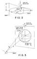
- Figure 3 is illustrative of cone-beam geometry;
- Figure 4 is illustrative of the generation of theintermediate function G(β,Φ) ;
- FIGURE 5 illustrates the local coordinate systemfor the projection data;
- FIGURES 6A and 6B illustrate regions of the planenormal to group I and group II;
- FIGURE 7 illustrates the linear orbitrelationships in which the filter is spatially varying withdifferent filters for different rows.
- With reference to FIGURE 1, a cone-beam radiationdetection means, such as one or more
gamma camera heads 10,each with a cone-beam collimator 12, is mounted to moverotationally around and linearly along anexaminationregion 14. The cone-beam collimator 12 has a plurality ofpaths defined by bores in a solid lead sheet or by leadvanes which focus at afocal point 16. The cone-beamcollimator is oriented such that thefocal point 16 isdisposed across the examination region from a subject18.Radiation emanating from the subject or passing through thesubject follows diverging paths through the collimator tothe gamma camera head or other detector. In this manner,a relatively small region of the subject is projected ontoa relatively large region of a crystal face of thedetectorhead 10, i.e. an effective magnification. - The detector heads are mounted on a gantry meansor
portion 20. The gantry means includes a plurality ofmotor drives 22 which can be operated individually or incombination in order to move the detector heads alongselectable orbits. The heads are rotated along a circularorbit and the gantry is translated to move the heads alonga line orbit. Anorbit controller 24 generates motorcontrol signals for each of the motors to cause the headsto move along the selected orbit. More specific to theillustrated embodiment, the orbit controller includes alook-up table26 which is preprogrammed to the position andorientation in which the detector heads and gantry should be at each incremental stage of the orbit. The look-uptable is preprogrammed with the appropriate positions whichthe gantry should take in order to move in the line orbitand the appropriate positions that the head should takewhen it moves in a circular orbit. A current positionsensing means28 monitors the current position of thedetector head(s), such as by monitoring the angularposition around the subject, the radial position toward andaway from the subject, and the longitudinal position alongthe subject. A comparing means30 compares the look-uptable values with the actual rotational and longitudinalpositions of the detector heads and gantry. A series ofmotor drivers 32 supply motive power to the motors orlinear drive means22 until the monitored current positionmatches the desired position from the look-up table.Optionally, descriptions of other orbits may be loaded intothe look-up table24. - The gantry or an associated control consoleincludes a data processing means for processing the outputdata from the detector head(s). More specifically, eachdetector head conventionally includes a scintillationcrystal that is viewed by an array of photomultipliertubes. Each time a radiation event occurs, the radiationpassing through the collimator and striking the crystalcauses a light flash or scintillation. The photomultipliertubes nearest the scintillation respond with proportionaloutput signals. Position and energy resolving circuitryconnected to the photomultiplier tubes determine the energyand position, hence the ray or direction along which theradiation travelled from the radiation event within thesubject through the collimator to the detector head. Dueto the cone-beam collimator, there is a direct relationshipbetween the x, y position on the scintillation crystal atwhich the radiation was received and the directional vectorβ of the ray. See FIGURE 3.
- Output datagcircle(β ,Φ) from the head during thecircular orbitΦ is stored in a
circular orbit memory 42c.Analogously, output data generated during the linear orline orbitgline(β,Φ) is stored in a line orbit memory42ℓ.Zero padding means44c and44ℓ add zeros around thecollected two-dimensional datag(β,Φ)to enlarge the datato the next largest array which is an even power of 2 (e.g.128 X 128; 256 X 256; 512 X 512; etc.). In the preferredembodiment, the circular and line orbit memories have thislarger capacity and the zero padding means merely fills theunused memory cells with zeros. By surrounding the datawith zeros in this manner, aliasing in the constructedimage is reduced. - With continuing reference to FIGURE 1 and furtherreference to FIGURE 2, the full ray transform of the circledata is multiplied by a two-dimensional filter kernelFcircle(ω) in the frequency domain which is defined as:
- More specifically, a Fourier transform means50ctransforms the datagcircle into the frequency domain.Preferably, the transform means50c performs a two-dimensionalfast Fourier transform. A filter means52cmonitors the circular orbit memory datagcircle to determinewhetherD|ωy| is greater than halfa|ωx|. Frequencycomponents are kept if the ratio of the frequency component in x (x is parallel to the plane of the circular orbit)over the frequency component in y(y is parallel to the axisof rotation) is greater than or equal to the ratio of twotimes the focal length over one half the length of thelinear translation. Frequency components that do notsatisfy this condition are discarded. A multiplying
means 54c multiplies each Fourier transformed value by one orzero, i.e. keeps or discards it, in accordance with thefilter functionFcircle and Equation (1). A frequency domainto spatial domain transform means56c transforms thefiltered circular orbit data back to the spatial domain.The resultant filtered spatial domain datags(,λ) isstored in a filtered spatial domain data memory58c. Inthis manner, the circular orbit data is transformed intothe frequency domain, filtered or edited to removeredundant data with the line orbit data, and returned tothe spatial domain. - The line orbit datagline is also transformed intothe frequency domain and filtered. However, the filter forthe line orbit data is spatially varying. That is, adifferent filter kernel is needed for each row of data,where a row is parallel to the circular orbit plane.
- More specifically to the preferred embodiment, aspatial to frequency domain transform means50ℓ, such as afast Fourier transform means, transforms the zero paddedline datagline into the frequency domain. In the frequencydomain, data is operated upon with a series of line orbitfiltersFline(ω,1), Fline(ω,2), ...,Fline(ω,n) to remove theredundant data with the circular orbit. The line filterfunction is defined as:
- A frequency domain to spatial domain transformmeans56ℓ transforms the two-dimensional data from thefrequency domain back to the spatial domain to generatefiltered data valuesgs(,λ). A switching means60switches filtered line orbit data into rows of a filteredline orbit data means58ℓ. More specifically,
row 1 of thedata filtered by filterFline(ω,1) is loaded intorow 1 ofthe memory58ℓ and row -1 of the data filtered by filterFline(ω,1) is loaded into row -1 of the memory58ℓ.Similarly, the ± mth row of the data filtered by filterFline(ω,m) is loaded into the ± mth row of the memory58ℓ. Rows of memory58ℓ beyond the ± nth rows are loaded withzeros. - The line orbit and circular orbit data arereconstructed into the image representation by weightingand convolution backprojection. Preweighting means70c and70ℓ preweight the data values in memories58c and58ℓ.Convolution means72c and72ℓ convolve each row of weighteddata with a convolution functionHg(β·γ). The filterkernelHg(β·γ) illustrated in FIGURE 4 is preferably aconvolution function defined as:
Backprojectors 74c and74ℓ backproject the circular orbitconvolved data and the line orbit convolved data,respectively. A summingmeans 76 adds the backprojectedcircle and line orbit data into animage memory 78. Aresultant imagef(x,y,z) for the circular volume of radiusR is created in theimage memory 78. Selected portions,planes, and projections of the image data in theimagememory 78 are selectively displayed on avideo monitor 80or other conventional display medium. - The cone-beam geometry is shown in FIGURE 3. Thefocal point trajectory is referred to as "orbit". Thefocal lengthD is the distance between the focal point andthe axis of rotation. The detection planeP is assumed tobe at the axis of rotation. This assumption is alwaysvalid if one scales up the object by moving the axis ofrotation on the detection plane when reconstructing the image. The object density function isf(x), wherex is avector inR3. The cone-beam data may be expressed as:where Φ is the orbit vector for the location of the focalpoint, andβ is a unit-vector of the ray direction. Thegoal is to reconstruct the objectf(x) from the cone-beamprojectionsg (β,Φ).

- Smith,supra, defined a one-dimensional filterkernel as:whereS denotes (any) half of the unit sphere, anddγ isthe surface element on the unit sphere.

- Modified projection datags is obtained fromGby:where and are the azimuth and longitude of vectorβL,respectively in the local coordinate system as shown inFIGURE 5, andλ∈Λ is the real parameter of orbitΦ. InEquation (9), the functionM(βL,Φ) denotes the number oftimes the orbit intersects the plane which is representedby the normal vectorβL and passes through pointΦ(λ).Finally, the inversion formula is:
 It is observed that Equation (10) is the same as Feldkamp'salgorithm if the orbit is a circle(|Φ'(λ)|=D) andgs iscone-beam projection data.
- Ifgs is easily obtained, the image f(x) can bereconstructed by Equation (10). The difficulty lies inevaluating Equation (9), where the functionM(βL,Φ) is verycomplicated. For the one-circle and a perpendicular-lineorbit geometry,M(βL,Φ) can take values of 1, 2, 3, andinfinity. There hardly exists an analytical expression forM(βL,Φ).
- In order to simplify the evaluation ofgs, oneshould study Equations (8) and (9) first. FIGURE 4illustrates an intuition of Equation (8). At a fixed focalpoint locationΦ which is associated with a detection planePΦ consider a directionβ. The unit vectorβ has anazimuth and a longitude, where is in the orbit planewhich is spanned by Φ(λ) andΦ'(λ). The inner productβ·γ=constant corresponds to a straight line on the detection planePΦ. In FIGURE 4,β·γ0 = 0. The intermediate functionG(β,Φ) can be formed in three steps. (1) Treat thedetection planePΦ as a two-dimensional image plane, andperform parallel projection along the direction of β·γ =constant. (2) Weight the one-dimensional projected data byHg(β·γ). (3) Integrate these weighted one-dimensional datato obtain the value ofG(β,Φ). Thus, one may refer toEquation (8) as "projection" and "filtering".
- FIGURE 5 depicts the procedure in Equation (9).If one again treats the detection planePΦ as a two-dimensionalimage plane, this is a "weightedbackprojection". In FIGURE 5, a local coordinate system isused, where the longitude of vectorβL is fixed, and theazimuth is varying. The vector γ is orthogonal to allthese varyingβL's. IfM(βL,Φ) = 1, gs is thebackprojection ofG(βL,Φ), andgs(,λ) = g(γ,Φ) because thiswhole procedure is the standard filter backprojectionalgorithm. Usually,M(βL,Φ) is not constant, thebackprojection is weighted by1/M(βL,Φ), and thusgs(,λ)≠g(γ,Φ).
- Referring to FIGURE 2, the orbits consist of acircle (in the x-y plane) and a perpendicular line(parallel to the z-axis). Suppose that the object isdefined in the sphere∥X∥<R as shown in FIGURE 2, then therequired half-lengtha of the line-orbit is2DR(D2-R2)-1/2.Any plane cutting through the object will intersect theorbit, and may intersect the
orbit - The plane that cuts through the object isreferred to as to a "cutting plane", and the "plane angle"is defined as the angle made of the plane normal to the z-axis.A cutting plane with a plane angle less thansin-1(R/D) intersects the linear orbit; and a cutting planewith a plane angle greater thansin-1(R/D) intersects thecircular orbit. Some cutting planes may intersect bothorbits. The cutting planes can be divided into two groups: (1) with plane angle >sin-1(R/D), and (2) with plane angle<sin-1(R/D) as shown in FIGURE 6. The circular orbit isused to reconstruct the data from group one, and use thelinear orbit to reconstruct the data from group two. Thecircular orbit offers all the data in group one, and somedata not in group one. The data not in group one arediscarded by reducing the integral interval in Equation(9). For the circular orbit, therefore, one can useM(βL,Φ) ≡2 in Equation (9) with modified integral limits.
- Employing the two-dimensional central-slicetheorem, the modification procedure of Equations (8) and(9) is equivalent to filteringg(β,Φ) byFcircle(ω), which isa two-dimensional filter kernel in the frequency domain andis defined by:
- The linear orbit offers all the data in grouptwo, and some data not in group two. The data not in grouptwo are discarded by reducing the integral interval inEquation (9). For the linear orbit therefore, one can useM(βL,Φ) = 1 in Equation (9) with modified integral limits.However, due to the cone-shape in FIGURE 6, there exists no filter in the frequency domain, similar toFcircle (ω), thatcan be used to discard the unwanted data. A spatiallyvarying two-dimensional filter is required, one filterkernel for each row. If each spatial domain filter kernelis transformed into the frequency domain one has:
row


Claims (11)
- An apparatus for generating an image representation of an interior portion of a subject(18) disposed in an examination region (14), the apparatus comprising: radiation detection means(10, 12) for receiving radiation from the examination region (14) travelling along a cone of rayswhich converge at a focal point (16) and generating electrical data indicative thereof; and imagememory means (78) for storing a three-dimensional image representationcharacterised in thatit comprises means (10, 22, 24) for moving the radiation detection means (10, 12) in a circularorbit rotationally around the examination region (14) such that the radiation detection meansgenerates circular orbit data and in a line orbit linearly along the examination region (14) suchthat the radiation detection means (10, 12) generates line orbit data; Fourier transform means(50c) for transforming the circular orbit and line orbit data into a frequency domain; circular orbitfiltering means (52c) for filtering the frequency domain circular orbit data to discard a portionwhich is redundant with the line orbit data; line orbit filtering means (5211, 5212 .... 521n) forrepeatedly filtering the line orbit data with a series of spatially variant line orbit data filterfunctions (Fline) to discard a portion which is redundant with the circle orbit data, each line orbitdata filter function corresponding to one of a plurality of rows of line orbit data; inverse Fouriertransforming means (56c, 561) for transforming a filtered circular orbit data and the filtered lineorbit data from the frequency domain to a spatial domain; and backprojection means (74c, 741)for reconstructing the spatial domain filtered circular orbit data and line orbit data into the three-dimensionalimage representation, wherein the circular orbit filtering means (52c) is arranged tooperate on the frequency domain circular orbit data with a filter function (Fcircle) which assumesa value of 1 when a ratio of a frequency component in a direction parallel to a plane of thecircular orbit over a frequency component in a direction parallel to an axis of rotation is greaterthan or equal to a ratio of twice a focal length over one half a length of the line orbit (a|ωx|) andassumes a zero value otherwise, wherein the reconstructed image representation represents aspherical examination region, and wherein the frequency domain line orbit data filter function(Fline) utilized by the line orbit filtering means (5211, 5212 ..... 521n) has a value of 1 when both (1)a ratio of a frequency component in a direction parallel to an axis of rotation over a frequencycomponent parallel to a plane of the circular orbit is greater than or equal to a ratio of a focallength over one half a length of a cord, along the corresponding row, with radius equal to onefourth a length of the line orbit and centered at a center of a radiation detector and (2) a distancebetween the corresponding row and a centermost row is smaller than one fourth the length of lineorbit and has a value of zero otherwise.
- An apparatus according to Claim 1 further including monitor means (80) for convertinga portion of the image representation into a man-readable display.
- An apparatus according to Claim 1 or 2 further including zero padding means (44c, 441)for adding zeros peripherally around the circular and line orbit data generated by the radiationdetection means (10, 12).
- An apparatus according to Claim 1, 2 or 3 further including: filtered line orbit datamemory means (581); switching means (60) for loading ± mth rows of the inverse Fouriertransformed data that was filtered with an mth of the line orbit data filter functions into ± mthrows of the filtered line orbit data memory means, the backprojecting means (74c, 741)reconstructing spatial domain filtered line orbit data from the filtered line orbit data memorymeans.
- An apparatus according to any preceding claim wherein the subject (18) is a patient whichis injected with a radiopharmaceutical and wherein the radiation detection means includes a cone-beamcollimator (12) mounted to a radiation receiving face of a gamma camera head (10).
- A method of reconstructing an image representation of an interior portion of a subject(18) disposed in an examination region (14) comprising: moving a radiation detection systemwhich receives radiation from the examination region (14) travelling along a cone of rays whichconverge at a focal point, said detection system being moved in (1) a circular orbit rotationallyaround the examination region (14) and (2) a line orbit linearly along the examination region (14)and collecting circular orbit and line orbit data;characterised in that it comprises: transformingthe circular orbit data into a frequency domain and filtering the circular orbit data in thefrequency domain to remove data which is redundant with the line orbit data; transforming theline orbit data into the frequency domain and filtering the line orbit data with a series of differentfilter functions (5211, 5212 ... 521n) to provide a plurality of rows of line orbit data each withredundant circular orbit data removed; and reconstructing the filtered circular and line orbit datainto a three-dimensional image representation, wherein the step of removing data which isredundant with the line orbit data includes operating on the frequency domain circular orbit datawith a filter function (Fcircle) which assumes a value of 1 when a ratio of a frequency componentin a direction parallel to a plane of the circular orbit over a frequency component in a directionparallel to an axis of rotation is greater than or equal to a ratio of twice a focal length over onehalf a length of the line orbit (a|ωx|) and assumes a zero value otherwise, wherein thereconstructed image representation represents a spherical examination region, and wherein thefrequency domain line orbit data filter function (Fline) has a value of 1 when both (1) a ratio of afrequency component in a direction parallel to an axis of rotation over a frequency componentparallel to a plane of the circular orbit is greater than or equal to a ratio of a focal length over onehalf a length of a cord, along the corresponding row, with radius equal to one fourth a length ofthe line orbit and centered at a center of a radiation detector and (2) a distance between thecorresponding row and a centermost row is smaller than one fourth the length of line orbit andhas a value of zero otherwise.
- A method according to Claim 6 wherein the line orbit has a length (a) equal to 2DR(D2- R2)-1/2, where R is a radius of the interior subject portion that is reconstructed into the imagerepresentation and D is a radius of the circular orbit.
- A method according to Claim 6 or 7 wherein the step of filtering the frequency domainline orbit data comprises in the frequency domain: (a) operating on the frequency domain datawith a first filter function to eliminate duplicative data relative to a first row, (b) repeating step(a) for a plurality of rows with corresponding filter functions, and further comprising the step oftransforming the circular orbit data and the rows of line orbit data from the frequency domain tothe spatial domain, prior to reconstruction.
- A method according to Claim 6, 7 or 8 further including converting a portion of the imagerepresentation into a man-readable display.
- A method according to any of Claims 6 to 9 further including expanding the size of thecircular and line orbit data by adding zeros peripherally therearound for reducing reconstructionartifacts.
- A method according to any of Claims 6 to 10 wherein the step of generating circular andline orbit data includes: injecting a subject (18) with a radiopharmaceutical; collimating radiationfrom the radiopharmaceutical through a cone-beam collimator; detecting radiation that hastraversed the cone-beam collimator with a gamma camera head (10); moving the gamma camerahead (10) in a circular orbit to collect the circular orbit data; and moving the gamma camera head(10) in a straight line transverse to the circular orbit to collect the line orbit data.
Applications Claiming Priority (2)
| Application Number | Priority Date | Filing Date | Title |
|---|---|---|---|
| US07/713,719US5170439A (en) | 1991-06-11 | 1991-06-11 | Cone beam reconstruction using combined circle and line orbits |
| US713719 | 1991-06-11 |
Publications (3)
| Publication Number | Publication Date |
|---|---|
| EP0525954A2 EP0525954A2 (en) | 1993-02-03 |
| EP0525954A3 EP0525954A3 (en) | 1993-11-18 |
| EP0525954B1true EP0525954B1 (en) | 2001-08-29 |
Family
ID=24867248
Family Applications (1)
| Application Number | Title | Priority Date | Filing Date |
|---|---|---|---|
| EP92305163AExpired - LifetimeEP0525954B1 (en) | 1991-06-11 | 1992-06-05 | Imaging methods and apparatus |
Country Status (3)
| Country | Link |
|---|---|
| US (1) | US5170439A (en) |
| EP (1) | EP0525954B1 (en) |
| JP (1) | JPH05324801A (en) |
Cited By (20)
| Publication number | Priority date | Publication date | Assignee | Title |
|---|---|---|---|---|
| US8423125B2 (en) | 2004-11-09 | 2013-04-16 | Spectrum Dynamics Llc | Radioimaging |
| US8489176B1 (en) | 2000-08-21 | 2013-07-16 | Spectrum Dynamics Llc | Radioactive emission detector equipped with a position tracking system and utilization thereof with medical systems and in medical procedures |
| US8492725B2 (en) | 2009-07-29 | 2013-07-23 | Biosensors International Group Ltd. | Method and system of optimized volumetric imaging |
| US8521253B2 (en) | 2007-10-29 | 2013-08-27 | Spectrum Dynamics Llc | Prostate imaging |
| US8565860B2 (en) | 2000-08-21 | 2013-10-22 | Biosensors International Group, Ltd. | Radioactive emission detector equipped with a position tracking system |
| US8571881B2 (en) | 2004-11-09 | 2013-10-29 | Spectrum Dynamics, Llc | Radiopharmaceutical dispensing, administration, and imaging |
| US8586932B2 (en) | 2004-11-09 | 2013-11-19 | Spectrum Dynamics Llc | System and method for radioactive emission measurement |
| US8606349B2 (en) | 2004-11-09 | 2013-12-10 | Biosensors International Group, Ltd. | Radioimaging using low dose isotope |
| US8610075B2 (en) | 2006-11-13 | 2013-12-17 | Biosensors International Group Ltd. | Radioimaging applications of and novel formulations of teboroxime |
| US8615405B2 (en) | 2004-11-09 | 2013-12-24 | Biosensors International Group, Ltd. | Imaging system customization using data from radiopharmaceutical-associated data carrier |
| US8620046B2 (en) | 2000-08-21 | 2013-12-31 | Biosensors International Group, Ltd. | Radioactive-emission-measurement optimization to specific body structures |
| US8644910B2 (en) | 2005-07-19 | 2014-02-04 | Biosensors International Group, Ltd. | Imaging protocols |
| US8676292B2 (en) | 2004-01-13 | 2014-03-18 | Biosensors International Group, Ltd. | Multi-dimensional image reconstruction |
| US8837793B2 (en) | 2005-07-19 | 2014-09-16 | Biosensors International Group, Ltd. | Reconstruction stabilizer and active vision |
| US8894974B2 (en) | 2006-05-11 | 2014-11-25 | Spectrum Dynamics Llc | Radiopharmaceuticals for diagnosis and therapy |
| US8909325B2 (en) | 2000-08-21 | 2014-12-09 | Biosensors International Group, Ltd. | Radioactive emission detector equipped with a position tracking system and utilization thereof with medical systems and in medical procedures |
| US9040016B2 (en) | 2004-01-13 | 2015-05-26 | Biosensors International Group, Ltd. | Diagnostic kit and methods for radioimaging myocardial perfusion |
| US9275451B2 (en) | 2006-12-20 | 2016-03-01 | Biosensors International Group, Ltd. | Method, a system, and an apparatus for using and processing multidimensional data |
| US9316743B2 (en) | 2004-11-09 | 2016-04-19 | Biosensors International Group, Ltd. | System and method for radioactive emission measurement |
| US9470801B2 (en) | 2004-01-13 | 2016-10-18 | Spectrum Dynamics Llc | Gating with anatomically varying durations |
Families Citing this family (77)
| Publication number | Priority date | Publication date | Assignee | Title |
|---|---|---|---|---|
| FR2675927B1 (en)* | 1991-04-25 | 1993-07-30 | Inst Nat Rech Inf Automat | METHOD AND DEVICE FOR ASSISTING INSPECTION OF A BODY, PARTICULARLY FOR TOMOGRAPHY. |
| US5404293A (en)* | 1991-06-11 | 1995-04-04 | The University Of Utah | Cone beam reconstruction using helical data collection paths |
| US5365560A (en)* | 1991-07-29 | 1994-11-15 | General Electric Company | Method and apparatus for acquiring a uniform distribution of radon data sufficiently dense to constitute a complete set for exact image reconstruction of an object irradiated by a cone beam source |
| US5333164A (en)* | 1991-12-11 | 1994-07-26 | General Electric Company | Method and apparatus for acquiring and processing only a necessary volume of radon data consistent with the overall shape of the object for efficient three dimensional image reconstruction |
| US5323007A (en)* | 1992-02-07 | 1994-06-21 | Univ. Of Chicago Development Corp. Argonne National Laboratories | Method of recovering tomographic signal elements in a projection profile or image by solving linear equations |
| US5375156A (en)* | 1992-03-31 | 1994-12-20 | Siemens Medical Systems, Inc. | Method and apparatus for 3-D computer tomography |
| FR2692061B1 (en)* | 1992-06-05 | 1994-07-22 | Commissariat Energie Atomique | METHOD FOR RECONSTRUCTING THREE-DIMENSIONAL IMAGES OF AN OBJECT BY MEASUREMENTS USING CONICAL RADIATION AND A TWO-DIMENSIONAL ARRAY OF DETECTORS. |
| US5377250A (en)* | 1992-08-07 | 1994-12-27 | General Electric Company | Reconstruction method for helical scanning computed tomography apparatus with multi-row detector array |
| US5278884A (en)* | 1992-12-18 | 1994-01-11 | General Electric Company | Complete 3D CT data acquisition using practical scanning paths on the surface of a sphere |
| FR2706043B1 (en)* | 1993-06-02 | 1995-07-07 | Commissariat Energie Atomique | Installation and method for reconstructing three-dimensional images. |
| US6219441B1 (en)* | 1993-06-22 | 2001-04-17 | General Electric Company | Reconstruction of images from three-dimensional cone beam data |
| US5400377A (en)* | 1993-07-16 | 1995-03-21 | General Electric Company | Artifact reduction method for tomographic image reconstruction using cross-plane rays |
| US5406479A (en)* | 1993-12-20 | 1995-04-11 | Imatron, Inc. | Method for rebinning and for correcting cone beam error in a fan beam computed tomographic scanner system |
| US5400255A (en)* | 1994-02-14 | 1995-03-21 | General Electric Company | Reconstruction of images from cone beam data |
| US5489782A (en)* | 1994-03-24 | 1996-02-06 | Imaging Laboratory, Inc. | Method and apparatus for quantum-limited data acquisition |
| CA2156141A1 (en)* | 1994-09-28 | 1996-03-29 | Kaveh Azar | Interactive scanning device or system |
| US5592523A (en)* | 1994-12-06 | 1997-01-07 | Picker International, Inc. | Two dimensional detector array for CT scanners |
| US5532490A (en)* | 1994-12-27 | 1996-07-02 | The University Of Utah | Displaced center-of-rotation fan-beam tomography for cardiac imaging |
| US6044170A (en)* | 1996-03-21 | 2000-03-28 | Real-Time Geometry Corporation | System and method for rapid shape digitizing and adaptive mesh generation |
| US5784481A (en)* | 1996-06-25 | 1998-07-21 | General Electric Company | CT cone beam image reconstruction with circle and line scan path |
| US5937102A (en)* | 1996-10-09 | 1999-08-10 | California Institute Of Technology | Image reconstruction |
| US5706325A (en)* | 1996-12-05 | 1998-01-06 | General Electric Company | Exact regional reconstruction of longitudinally-unbounded objects using a circle-and-line cone beam tomographic system |
| US5999587A (en)* | 1997-07-03 | 1999-12-07 | University Of Rochester | Method of and system for cone-beam tomography reconstruction |
| US6075836A (en) | 1997-07-03 | 2000-06-13 | University Of Rochester | Method of and system for intravenous volume tomographic digital angiography imaging |
| US6041132A (en)* | 1997-07-29 | 2000-03-21 | General Electric Company | Computed tomography inspection of composite ply structure |
| US6014419A (en)* | 1997-11-07 | 2000-01-11 | Hu; Hui | CT cone beam scanner with fast and complete data acquistion and accurate and efficient regional reconstruction |
| US6041097A (en) | 1998-04-06 | 2000-03-21 | Picker International, Inc. | Method and apparatus for acquiring volumetric image data using flat panel matrix image receptor |
| US6160924A (en)* | 1998-08-12 | 2000-12-12 | Northrop Grumman Corporation | Method for forming a map of a three-dimensional object |
| JP4698780B2 (en)* | 1998-09-15 | 2011-06-08 | シーメンス アクチエンゲゼルシヤフト | Image reconstruction method and measurement data acquisition method |
| DE19845133A1 (en)* | 1998-10-01 | 2000-04-06 | Philips Corp Intellectual Pty | Computed tomography procedure with a conical beam |
| US6104775A (en)* | 1998-10-29 | 2000-08-15 | Picker International, Inc. | 3D image reconstruction for helical partial cone beam scanners using wedge beam transform |
| US6461040B1 (en) | 1998-11-12 | 2002-10-08 | Koninklijke Philips Electronics N.V. | Apparatus and method to correct for position errors in diagnostic imaging |
| US6092928A (en)* | 1998-11-12 | 2000-07-25 | Picker International, Inc. | Apparatus and method to determine the relative position of a detector array and an x-ray tube focal spot |
| EP1138159B1 (en) | 1998-12-07 | 2015-06-17 | Universal City Studios LLC | Image correction method to compensate for point of view image distortion |
| US6343108B1 (en) | 1999-06-18 | 2002-01-29 | Philips Medical Systems (Cleveland), Inc. | Cone beam scanner using oblique surface reconstructions |
| US6263040B1 (en)* | 1999-08-10 | 2001-07-17 | General Electric Company | Methods and apparatus for cone-tilted parallel sampling and reconstruction |
| US6480565B1 (en)† | 1999-11-18 | 2002-11-12 | University Of Rochester | Apparatus and method for cone beam volume computed tomography breast imaging |
| US6987831B2 (en)* | 1999-11-18 | 2006-01-17 | University Of Rochester | Apparatus and method for cone beam volume computed tomography breast imaging |
| WO2001060258A1 (en) | 2000-02-15 | 2001-08-23 | Philips Medical Systems Technologies Ltd. | Clinical screening ct systems |
| US7065242B2 (en)* | 2000-03-28 | 2006-06-20 | Viewpoint Corporation | System and method of three-dimensional image capture and modeling |
| US6504892B1 (en) | 2000-10-13 | 2003-01-07 | University Of Rochester | System and method for cone beam volume computed tomography using circle-plus-multiple-arc orbit |
| US6628983B1 (en)* | 2000-10-25 | 2003-09-30 | Koninklijke Philips Electronics N.V. | Nuclear imaging systems and methods with feature-enhanced transmission imaging |
| US6546067B2 (en)* | 2001-01-30 | 2003-04-08 | Kabushiki Kaisha Toshiba | Reconstruction and scan of 4D-CT |
| US6477221B1 (en) | 2001-02-16 | 2002-11-05 | University Of Rochester | System and method for fast parallel cone-beam reconstruction using one or more microprocessors |
| WO2005107598A1 (en)* | 2003-12-04 | 2005-11-17 | Research Foundation Of The University Of Central Florida, Incorporated | Efficient circle and line cone beam computed tomography |
| US7197105B2 (en)* | 2001-08-16 | 2007-03-27 | Research Foundation Of The University Of Central Florida, Inc. | Efficient image reconstruction algorithm for the circle and line cone beam computed tomography |
| US7280632B2 (en)* | 2001-08-16 | 2007-10-09 | University Of Central Florida Research Foundation, Inc. | Exact filtered back projection (FBP) algorithm for spiral computer tomography with variable pitch |
| US7305061B2 (en)* | 2001-08-16 | 2007-12-04 | Research Foundation Of The University Of Central Florida | Efficient image reconstruction algorithm for the circle and arc cone beam computer tomography |
| US7127096B2 (en)* | 2001-11-20 | 2006-10-24 | Accuimage Diagnostics Corp. | Method and software for improving coronary calcium scoring consistency |
| US7149331B1 (en) | 2002-09-03 | 2006-12-12 | Cedara Software Corp. | Methods and software for improving thresholding of coronary calcium scoring |
| DE10245116A1 (en)* | 2002-09-27 | 2004-04-08 | Siemens Ag | Computer tomography method in which both circle and live scanning are used, whereby absorption image values obtained during live or linear sampling are obtained in a single continuous linear sampling movement |
| DE10252662A1 (en)* | 2002-11-11 | 2004-05-27 | Philips Intellectual Property & Standards Gmbh | Medical computer tomography procedure has source rotated around object and back projection image reconstruction using square law distance and cosine beam angle weighting |
| US6647084B1 (en)* | 2002-11-11 | 2003-11-11 | Ge Medical Systems Global Technology Company, Llc | Method and apparatus for filtering projection data of a helical scan |
| US6983034B2 (en)* | 2003-02-14 | 2006-01-03 | University Of Iowa Research Foundation | Methods and devices for CT reconstruction using a grangeat approach |
| US7180975B2 (en)* | 2003-02-14 | 2007-02-20 | Koninklijke Philips Electronics N.V. | System and method for exact image reconstruction for helical cone beam computed tomography including redundant data |
| US9039618B2 (en)* | 2003-07-24 | 2015-05-26 | Hewlett-Packard Development Company, L.P. | Medical imaging device and method |
| US7968851B2 (en) | 2004-01-13 | 2011-06-28 | Spectrum Dynamics Llc | Dynamic spect camera |
| US9943274B2 (en) | 2004-11-09 | 2018-04-17 | Spectrum Dynamics Medical Limited | Radioimaging using low dose isotope |
| WO2006051468A1 (en)* | 2004-11-15 | 2006-05-18 | Philips Intellectual Property & Standards Gmbh | Reconstruction method for computer tomograph and computer tomograph |
| WO2006120609A1 (en)* | 2005-05-12 | 2006-11-16 | Philips Intellectual Property & Standards Gmbh | Continuous computer tomography performing super-short-scans and stronger weighting of most recent data |
| CN100495439C (en)* | 2005-11-21 | 2009-06-03 | 清华大学 | Image reconstruction system and method using linear trajectory scanning |
| WO2007098284A2 (en)* | 2006-02-27 | 2007-08-30 | University Of Rochester | Method and apparatus for cone beam ct dynamic imaging |
| US7983385B2 (en)* | 2006-09-29 | 2011-07-19 | Koninklijke Philips Electronics N.V. | Fly-by scanning |
| US8270559B2 (en)* | 2006-11-24 | 2012-09-18 | Kabushiki Kaisha Toshiba | Method and system for tomographic reconstruction in medical imaging using the circle and line trajectory |
| JP2008237886A (en)* | 2007-02-28 | 2008-10-09 | Toshiba Corp | X-ray CT apparatus and control method thereof |
| JP2009006133A (en)* | 2007-05-31 | 2009-01-15 | Toshiba Corp | X-ray CT apparatus and control method thereof |
| US7848479B1 (en) | 2007-06-29 | 2010-12-07 | University Of Central Florida Research Foundation, Inc. | Image reconstruction for a general circle-plus trajectory |
| CN101126723B (en)* | 2007-09-30 | 2011-06-22 | 西北工业大学 | Beam Hardening Correction Method for Cone Beam CT Based on Slice Contour Reprojection |
| US8023767B1 (en) | 2008-03-10 | 2011-09-20 | University Of Rochester | Method and apparatus for 3D metal and high-density artifact correction for cone-beam and fan-beam CT imaging |
| JP4665019B2 (en)* | 2008-08-18 | 2011-04-06 | 株式会社東芝 | X-ray computed tomography system |
| US8346007B2 (en) | 2009-12-22 | 2013-01-01 | Carestream Health, Inc. | Noise suppression in cone beam CT projection data |
| US8824753B2 (en) | 2011-10-06 | 2014-09-02 | Carestream Health, Inc. | Task oriented noise suppression in medical images |
| JP2013176468A (en)* | 2012-02-28 | 2013-09-09 | Canon Inc | Information processor and information processing method |
| US9091628B2 (en) | 2012-12-21 | 2015-07-28 | L-3 Communications Security And Detection Systems, Inc. | 3D mapping with two orthogonal imaging views |
| US9364191B2 (en) | 2013-02-11 | 2016-06-14 | University Of Rochester | Method and apparatus of spectral differential phase-contrast cone-beam CT and hybrid cone-beam CT |
| US9420976B2 (en) | 2014-03-19 | 2016-08-23 | General Electric Company | Systems and methods for optimized source collimation |
| CN111956306B (en)* | 2020-08-06 | 2022-05-27 | 扬州大学附属医院 | Puncture guide system based on multi-modal medical image information |
Family Cites Families (9)
| Publication number | Priority date | Publication date | Assignee | Title |
|---|---|---|---|---|
| JPS5394787A (en)* | 1977-01-31 | 1978-08-19 | Toshiba Corp | Tomographic diagnostic equipment by radiation |
| JPS56136529A (en)* | 1980-03-28 | 1981-10-24 | Tokyo Shibaura Electric Co | Apparatus for reconstituting image |
| US4616318A (en)* | 1983-06-07 | 1986-10-07 | Elscint, Inc. | System for reprojecting images using transform techniques |
| US4606004A (en)* | 1984-03-21 | 1986-08-12 | General Electric Company | Apparatus for reduction of filtration truncation errors |
| JPS61185256A (en)* | 1985-02-13 | 1986-08-18 | 株式会社日立メデイコ | X-ray ct image processor |
| IL83233A (en)* | 1987-07-17 | 1991-01-31 | Elscint Ltd | Reconstruction in ct scanners using divergent beams |
| US4851984A (en)* | 1987-08-03 | 1989-07-25 | University Of Chicago | Method and system for localization of inter-rib spaces and automated lung texture analysis in digital chest radiographs |
| US4969110A (en)* | 1988-08-01 | 1990-11-06 | General Electric Company | Method of using a priori information in computerized tomography |
| US5276614A (en)* | 1989-11-17 | 1994-01-04 | Picker International, Inc. | Dynamic bandwidth reconstruction |
- 1991
- 1991-06-11USUS07/713,719patent/US5170439A/ennot_activeExpired - Lifetime
- 1992
- 1992-06-05EPEP92305163Apatent/EP0525954B1/ennot_activeExpired - Lifetime
- 1992-06-09JPJP4174825Apatent/JPH05324801A/enactivePending
Cited By (24)
| Publication number | Priority date | Publication date | Assignee | Title |
|---|---|---|---|---|
| US8620046B2 (en) | 2000-08-21 | 2013-12-31 | Biosensors International Group, Ltd. | Radioactive-emission-measurement optimization to specific body structures |
| US8489176B1 (en) | 2000-08-21 | 2013-07-16 | Spectrum Dynamics Llc | Radioactive emission detector equipped with a position tracking system and utilization thereof with medical systems and in medical procedures |
| US9370333B2 (en) | 2000-08-21 | 2016-06-21 | Biosensors International Group, Ltd. | Radioactive-emission-measurement optimization to specific body structures |
| US8565860B2 (en) | 2000-08-21 | 2013-10-22 | Biosensors International Group, Ltd. | Radioactive emission detector equipped with a position tracking system |
| US8909325B2 (en) | 2000-08-21 | 2014-12-09 | Biosensors International Group, Ltd. | Radioactive emission detector equipped with a position tracking system and utilization thereof with medical systems and in medical procedures |
| US9470801B2 (en) | 2004-01-13 | 2016-10-18 | Spectrum Dynamics Llc | Gating with anatomically varying durations |
| US9040016B2 (en) | 2004-01-13 | 2015-05-26 | Biosensors International Group, Ltd. | Diagnostic kit and methods for radioimaging myocardial perfusion |
| US8676292B2 (en) | 2004-01-13 | 2014-03-18 | Biosensors International Group, Ltd. | Multi-dimensional image reconstruction |
| US8586932B2 (en) | 2004-11-09 | 2013-11-19 | Spectrum Dynamics Llc | System and method for radioactive emission measurement |
| US8615405B2 (en) | 2004-11-09 | 2013-12-24 | Biosensors International Group, Ltd. | Imaging system customization using data from radiopharmaceutical-associated data carrier |
| US8620679B2 (en) | 2004-11-09 | 2013-12-31 | Biosensors International Group, Ltd. | Radiopharmaceutical dispensing, administration, and imaging |
| US9316743B2 (en) | 2004-11-09 | 2016-04-19 | Biosensors International Group, Ltd. | System and method for radioactive emission measurement |
| US8571881B2 (en) | 2004-11-09 | 2013-10-29 | Spectrum Dynamics, Llc | Radiopharmaceutical dispensing, administration, and imaging |
| US8606349B2 (en) | 2004-11-09 | 2013-12-10 | Biosensors International Group, Ltd. | Radioimaging using low dose isotope |
| US8423125B2 (en) | 2004-11-09 | 2013-04-16 | Spectrum Dynamics Llc | Radioimaging |
| US8748826B2 (en) | 2004-11-17 | 2014-06-10 | Biosensor International Group, Ltd. | Radioimaging methods using teboroxime and thallium |
| US8837793B2 (en) | 2005-07-19 | 2014-09-16 | Biosensors International Group, Ltd. | Reconstruction stabilizer and active vision |
| US8644910B2 (en) | 2005-07-19 | 2014-02-04 | Biosensors International Group, Ltd. | Imaging protocols |
| US8894974B2 (en) | 2006-05-11 | 2014-11-25 | Spectrum Dynamics Llc | Radiopharmaceuticals for diagnosis and therapy |
| US8610075B2 (en) | 2006-11-13 | 2013-12-17 | Biosensors International Group Ltd. | Radioimaging applications of and novel formulations of teboroxime |
| US9275451B2 (en) | 2006-12-20 | 2016-03-01 | Biosensors International Group, Ltd. | Method, a system, and an apparatus for using and processing multidimensional data |
| US8521253B2 (en) | 2007-10-29 | 2013-08-27 | Spectrum Dynamics Llc | Prostate imaging |
| US8748827B2 (en) | 2009-07-29 | 2014-06-10 | Biosensors International Group, Ltd. | Method and system of optimized volumetric imaging |
| US8492725B2 (en) | 2009-07-29 | 2013-07-23 | Biosensors International Group Ltd. | Method and system of optimized volumetric imaging |
Also Published As
| Publication number | Publication date |
|---|---|
| US5170439A (en) | 1992-12-08 |
| JPH05324801A (en) | 1993-12-10 |
| EP0525954A2 (en) | 1993-02-03 |
| EP0525954A3 (en) | 1993-11-18 |
Similar Documents
| Publication | Publication Date | Title |
|---|---|---|
| EP0525954B1 (en) | Imaging methods and apparatus | |
| EP0592093B1 (en) | Imaging methods and apparatus | |
| US6282256B1 (en) | Computed tomography method utilizing a conical radiation beam | |
| EP0492895B1 (en) | Reconstructing 3-D images | |
| EP0997849B1 (en) | Image reconstruction | |
| US6865246B2 (en) | True 3D cone-beam imaging method and apparatus | |
| US7418073B2 (en) | Computed tomography device and method with three-dimensional backprojection | |
| US6990167B2 (en) | Image reconstruction method for divergent beam scanner | |
| US6285733B1 (en) | Computed tomography method utilizing a conical radiation beam | |
| US6678346B2 (en) | Cone-beam CT scanner with image reconstruction using multiple sub-images | |
| EP0520778B1 (en) | Tomographic image reconstruction using cross-plane rays | |
| US20040179643A1 (en) | Apparatus and method for reconstruction of volumetric images in a divergent scanning computed tomography system | |
| US6574298B2 (en) | Cone beam scanner using oblique surface reconstructions | |
| US20030072406A1 (en) | Versatile cone-beam imaging apparatus and method | |
| US5341460A (en) | Method and apparatus for producing a three-dimensional computerized tomography image of an object with improved conversion of cone beam data to radon data | |
| US7251307B2 (en) | Fan-beam and cone-beam image reconstruction using filtered backprojection of differentiated projection data | |
| CN1969760A (en) | X-ray ct method and x-ray ct apparatus | |
| JP2006503619A (en) | Cone beam computed tomography | |
| EP1644897B1 (en) | A fourier tomographic image reconstruction method for fan-beam data | |
| WO1995022115A1 (en) | Reconstruction of images from cone beam data | |
| US5708691A (en) | X-ray computed tomographic imaging device and x-ray computed tomographic method | |
| US5400377A (en) | Artifact reduction method for tomographic image reconstruction using cross-plane rays | |
| US6560308B1 (en) | Method and system for approximating missing data in cone beam x-ray CT reconstruction | |
| US7529335B2 (en) | Voxel-driven spiral reconstruction for cone-beam computer tomography | |
| US5532490A (en) | Displaced center-of-rotation fan-beam tomography for cardiac imaging |
Legal Events
| Date | Code | Title | Description |
|---|---|---|---|
| PUAI | Public reference made under article 153(3) epc to a published international application that has entered the european phase | Free format text:ORIGINAL CODE: 0009012 | |
| AK | Designated contracting states | Kind code of ref document:A2 Designated state(s):FR GB NL | |
| PUAL | Search report despatched | Free format text:ORIGINAL CODE: 0009013 | |
| AK | Designated contracting states | Kind code of ref document:A3 Designated state(s):FR GB NL | |
| 17P | Request for examination filed | Effective date:19940511 | |
| 17Q | First examination report despatched | Effective date:19960702 | |
| GRAG | Despatch of communication of intention to grant | Free format text:ORIGINAL CODE: EPIDOS AGRA | |
| RIC1 | Information provided on ipc code assigned before grant | Free format text:7G 06T 11/00 A | |
| GRAG | Despatch of communication of intention to grant | Free format text:ORIGINAL CODE: EPIDOS AGRA | |
| GRAH | Despatch of communication of intention to grant a patent | Free format text:ORIGINAL CODE: EPIDOS IGRA | |
| RAP1 | Party data changed (applicant data changed or rights of an application transferred) | Owner name:THE UNIVERSITY OF UTAH Owner name:MARCONI MEDICAL SYSTEMS, INC. | |
| GRAH | Despatch of communication of intention to grant a patent | Free format text:ORIGINAL CODE: EPIDOS IGRA | |
| GRAA | (expected) grant | Free format text:ORIGINAL CODE: 0009210 | |
| AK | Designated contracting states | Kind code of ref document:B1 Designated state(s):FR GB NL | |
| ET | Fr: translation filed | ||
| REG | Reference to a national code | Ref country code:GB Ref legal event code:IF02 | |
| PLBE | No opposition filed within time limit | Free format text:ORIGINAL CODE: 0009261 | |
| STAA | Information on the status of an ep patent application or granted ep patent | Free format text:STATUS: NO OPPOSITION FILED WITHIN TIME LIMIT | |
| 26N | No opposition filed | ||
| PGFP | Annual fee paid to national office [announced via postgrant information from national office to epo] | Ref country code:NL Payment date:20030513 Year of fee payment:12 | |
| REG | Reference to a national code | Ref country code:GB Ref legal event code:732E | |
| REG | Reference to a national code | Ref country code:FR Ref legal event code:CD | |
| REG | Reference to a national code | Ref country code:GB Ref legal event code:746 Effective date:20040504 | |
| REG | Reference to a national code | Ref country code:FR Ref legal event code:TQ | |
| PG25 | Lapsed in a contracting state [announced via postgrant information from national office to epo] | Ref country code:NL Free format text:LAPSE BECAUSE OF NON-PAYMENT OF DUE FEES Effective date:20050101 | |
| NLV4 | Nl: lapsed or anulled due to non-payment of the annual fee | Effective date:20050101 | |
| PGFP | Annual fee paid to national office [announced via postgrant information from national office to epo] | Ref country code:GB Payment date:20050628 Year of fee payment:14 Ref country code:FR Payment date:20050628 Year of fee payment:14 | |
| PG25 | Lapsed in a contracting state [announced via postgrant information from national office to epo] | Ref country code:GB Free format text:LAPSE BECAUSE OF NON-PAYMENT OF DUE FEES Effective date:20060605 | |
| GBPC | Gb: european patent ceased through non-payment of renewal fee | Effective date:20060605 | |
| REG | Reference to a national code | Ref country code:FR Ref legal event code:ST Effective date:20070228 | |
| PG25 | Lapsed in a contracting state [announced via postgrant information from national office to epo] | Ref country code:FR Free format text:LAPSE BECAUSE OF NON-PAYMENT OF DUE FEES Effective date:20060630 |