EP0525098B1 - Keratome for making arc-shaped incisions - Google Patents
Keratome for making arc-shaped incisionsDownload PDFInfo
- Publication number
- EP0525098B1 EP0525098B1EP91908771AEP91908771AEP0525098B1EP 0525098 B1EP0525098 B1EP 0525098B1EP 91908771 AEP91908771 AEP 91908771AEP 91908771 AEP91908771 AEP 91908771AEP 0525098 B1EP0525098 B1EP 0525098B1
- Authority
- EP
- European Patent Office
- Prior art keywords
- support
- relative
- axis
- blade
- longitudinal direction
- Prior art date
- Legal status (The legal status is an assumption and is not a legal conclusion. Google has not performed a legal analysis and makes no representation as to the accuracy of the status listed.)
- Expired - Lifetime
Links
- 210000004087corneaAnatomy0.000claimsabstractdescription30
- 201000009310astigmatismDiseases0.000claimsabstractdescription12
- 238000013519translationMethods0.000claimsdescription22
- 230000000295complement effectEffects0.000claimsdescription4
- 208000031968CadaverDiseases0.000description25
- 210000003128headAnatomy0.000description14
- 230000002093peripheral effectEffects0.000description9
- 238000011161developmentMethods0.000description7
- 230000018109developmental processEffects0.000description7
- 210000000887faceAnatomy0.000description7
- 230000000007visual effectEffects0.000description7
- 241001080024TellesSpecies0.000description5
- 230000006835compressionEffects0.000description2
- 238000007906compressionMethods0.000description2
- 238000012937correctionMethods0.000description2
- 239000003550markerSubstances0.000description2
- 238000000034methodMethods0.000description2
- 206010010356Congenital anomalyDiseases0.000description1
- 241000272186Falco columbariusSpecies0.000description1
- 208000001126KeratosisDiseases0.000description1
- 229910000639Spring steelInorganic materials0.000description1
- 238000004873anchoringMethods0.000description1
- 238000013459approachMethods0.000description1
- 239000000470constituentSubstances0.000description1
- 238000013461designMethods0.000description1
- 238000006073displacement reactionMethods0.000description1
- 230000000694effectsEffects0.000description1
- 230000007717exclusionEffects0.000description1
- 230000003100immobilizing effectEffects0.000description1
- 238000012423maintenanceMethods0.000description1
- 239000000463materialSubstances0.000description1
- 230000003287optical effectEffects0.000description1
- 230000035515penetrationEffects0.000description1
- 230000001105regulatory effectEffects0.000description1
- 230000000717retained effectEffects0.000description1
- 238000001356surgical procedureMethods0.000description1
- 230000002747voluntary effectEffects0.000description1
Images


Classifications
- A—HUMAN NECESSITIES
- A61—MEDICAL OR VETERINARY SCIENCE; HYGIENE
- A61F—FILTERS IMPLANTABLE INTO BLOOD VESSELS; PROSTHESES; DEVICES PROVIDING PATENCY TO, OR PREVENTING COLLAPSING OF, TUBULAR STRUCTURES OF THE BODY, e.g. STENTS; ORTHOPAEDIC, NURSING OR CONTRACEPTIVE DEVICES; FOMENTATION; TREATMENT OR PROTECTION OF EYES OR EARS; BANDAGES, DRESSINGS OR ABSORBENT PADS; FIRST-AID KITS
- A61F9/00—Methods or devices for treatment of the eyes; Devices for putting in contact-lenses; Devices to correct squinting; Apparatus to guide the blind; Protective devices for the eyes, carried on the body or in the hand
- A61F9/007—Methods or devices for eye surgery
- A61F9/013—Instruments for compensation of ocular refraction ; Instruments for use in cornea removal, for reshaping or performing incisions in the cornea
Definitions
- the present inventionrelates to a keratotome intended for making arcuate incisions in a cornea, for the correction of astigmatism.
- the purpose of the present inventionis to allow the making of arcuate incisions sufficiently precise to achieve results, regardless of the skill of the surgeon.
- such a keratotomeauthorizes the making of incisions in the form of a rigorous arc of circle, thereby concerning an area in which the cornea has a substantially constant thickness, and allows two important parameters to be controlled without difficulty, namely the depth of incision, adjusted by adjusting the projection that the point of the knife forms on the outside of the body in the cutting position, and the angular length of the incision.
- the keratotome illustratedis a type comprising two knives, but it is understood that it would not go beyond the scope of the present invention to produce, in accordance with the teachings thereof, a keratotome comprising a single knife, or possibly more than two knives .
- the illustrated keratotome 3comprises an external support 4 having the general shape of a frustoconical tubular wall of revolution around a axis 5 and enveloping an inner body or carriage 6 also having the shape of a tubular wall of revolution around the axis 5, mounted for rotation in the support around this axis 5 to the exclusion of any other possibility of relative movement.
- the external support 4diverges from a foot portion 7 intended to be applied to the anterior face 1 of the cornea 2 to be incised, around the location of the incisions to be made, up to a head portion 8 intended for its gripping by the non-dominant hand of the surgeon.
- the wall constituting the external support 4 in its foot part 7comprises an annular cavity 9, of revolution about the axis 5 and opening in the foot part 7 by an annular slot 10, delimited by two bearing surfaces 11, 12 annulars of revolution around the axis 5 and lying on the same reference surface 13.
- the reference surface 13is chosen so as to correspond to the majority of the anterior surfaces 1 of the cornea 2.
- the bearing surface 11 closest to the axis 5is constituted by an annular part 17 attached in rotation to the support 4, in an annular groove 18 of the latter, facing the axis 5.
- This grooveis delimited by two removable parts to allow changing the part 17 illustrated in Figures 1, 4, 5
- the part 17or any other part which may be substituted for them, comprises a peripheral skirt 20, 21, annular of revolution around the axis 5 with a shape closely complementary to that of the groove 18. Inside the skirt 20 or 21, the part 17 has a wall delimited by a flat, upper face 22, 23, perpendicular to the axis 5 and having, on the other face, determined shapes flush with the reference surface 13.
- the part 17has a transverse wall in the form of a crown 24, bounded by two plane faces 22, 25, and an annular edge 26.
- Four zones 27arranged in the same geometric cylinder not referenced, of radius R1, of angular length ⁇ 1 close to 90 °, alternate with four zones 28 of angular length ⁇ 2 of the order of a few degrees.
- Each of these zones 28carries on its face 25 an edge 29 in an arc of a circle 30 of radius R2 less than R1 and in practice greater than that of the clear zone of the cornea.
- the four edges 29allow precise positioning of the keratome 3 on the cornea 2, previously provided with a circular marking centered on the visual axis.
- the four edges 29are flush with the reference surface 13 for together constitute the contact surface 11 with the anterior face 1 of the cornea 2, on the circular marking of the same radius as the circle 30.
- the part 17may further comprise, projecting from its face 25 in the immediate vicinity of each edge 29, a group of teeth 31 preventing sliding of the keratoma on the anterior face 1 of the cornea; the part 17 is also entirely set back with respect to the reference surface 13.
- the external support 4comprises another internal annular groove 39 in its head zone 8 with a bottom 40 of diameter as large as possible taking into account the dimensions of the head part 8.
- the groove 39has two flat sides 41, 42, perpendicular to the axis 5.
- the sides 41 and 42open on respective faces 43, 44 of the external support 4, which are cylindrical of revolution around the axis 5 towards which they are turned, by means of a flange 45, for the sidewall 41 and directly for the sidewall 42.
- the support 4Under the face 43, the support 4 comprises a frustoconical face 46 converging towards its part of the foot 7.
- the external support 4is limited at the top by a flat face 47.
- the support 4which has just been described advantageously consists of several parts assembled together by means making it possible to dissociate them at will, so that it can be easily cleaned.
- the head 8 and foot 7 partsalthough mutually integral, can be separated at will at the level of the shoulder 45 so as to allow access to adjustment means which will be described later.
- the external support 4cooperates through the groove 39 and the face 44 with the internal body 6 to guide the latter in rotation about the axis 5 without any possibility of relative movement.
- the body 6carries a cylindrical face 48 of diameter slightly smaller than that of the face 44, opposite which it is placed without mutual contact.
- This face 48carries two shoulders 49 and 50 which form a radial projection and which are placed respectively facing the face 44 and facing the groove 39, in which the shoulder 50 engages.
- the shoulder 50is delimited by planar annular faces 51, 52 and by a cylindrical outer peripheral face 53 sliding on the bottom 40 throat 39.
- the faces 52 and 51 of the shoulder 50bear respectively against the sides 41 and 42 by means of a ball bearing 55, 56.
- the shoulder 49is delimited by planar annular faces 57, 58 and a face 59 of generally cylindrical shape of revolution around the axis 5, with a diameter substantially identical to that of the face 44 so as to establish by sliding contact another guide of the body 6 and of the support 4 in rotation about the axis 5.
- the face 59is hollowed out of gear teeth 60 regularly distributed angularly around the axis 5 so as to cooperate with manual drive means 61 of known design, for example described in document EP 0 047 190, which cooperate with the gear teeth 60 of the body 6 by means of a pinion 62 rotatably mounted on the support 4 around an axis 63 parallel to the axis 5, which pinion 62 locally crosses the face 44 of the support 4, towards axis 5, by a light 64 of c face 44.
- the body 6carries integrally but preferably removable for maintenance operations, two identical yokes 68, diametrically opposite. Each of these yokes 68 ensures the swiveling mounting of a respective knife holder 70 around an axis of articulation 69 relative to the body 6.
- the two axes 69are located perpendicularly to the same plane 205 including the axis 5 and merging with the plane identified in II in Figure 2 and symmetrically to each other with respect to a plane 204, also including axis 5 but perpendicular to plane 205, and are located both as far as possible of axis 5 and also as close as possible to the face 58 of the shoulder 49 of the body 6, that is to say of the face 47 of the head part 48 of the support 4 so as to be as distant as possible from the foot part 7 of it.
- the knife holder 70has a proper mean direction 71 perpendicular to the axis 69. It can thus be oriented relative to the axis 5 by rotating the knife holder 70 around the axis 69, relative to the yoke 68 and to the body 6.
- the proper mean direction 71 of each knife holder 70intersects the reference surface 13 within an area annular 76 thereof, of revolution about the axis 5 with a minimum radius R3 less than the above-mentioned radius R2 but nevertheless greater than that of the clear zone of a cornea 2.
- Meansare provided for immobilizing in a controlled manner each knife holder 70 in rotation about the axis 69.
- each yoke 68has a zone 72 forming a projection approximately parallel to the axis 5, relative to the face 52 of the shoulder 50 towards the foot part 7 of the support 4, this zone 72 being set back towards inside the support 4 with respect to the reference surface 13 and not coming into contact with any part of the support 4 although this zone 72 is located farther from the axis 5 than the knife holder 70.
- the yoke 68carries a crown 73, rotating around an axis 74 but without the possibility of translation along this axis 74; the axis 74 is located in the plane 205, offset with respect to the axis 69, towards the base part 7 of the support 4, and perpendicular to the proper direction 71 of the knife holder 70, with respect to which this axis 74 is fixed.
- the crown 73is thus disposed on the side of the zone 72 opposite the side of the latter facing the axis 5, in a position released by the foot part 7 of the support 4 when the latter is separated from the head part. 8 so as to then allow its manual rotation.
- this ring 73has graduations 80 visible when the foot part 7 is thus separated from the head part 8, these graduations being expressed for example in mm, and corresponding to incision diameters.
- the zone 72 of the yoke 68 or the knife holder 70itself carries a mark 75, for example in the form of a single line.
- the ring 73has a micrometric thread 77, engaged with a coaxial screw 78 mounted on the knife holder 70 in an integral manner.
- This spacing or offset R4determines an incision radius.
- the mounting of the crown 73 on the zone 72 of the yoke 68is carried out, as shown in FIG. 11, by engagement of a groove 254, annular of revolution around the axis 74, that presents the crown 73, in a slide 81 of the zone 72 of the yoke 68.
- This slide 81has the shape of a fork opening towards the foot part 7 and comprising two arms 250 symmetrical with respect to the plane 205 and s 'engaging in the groove 254 on either side of the axis 74.
- Each of the arms 250splits itself, towards the foot part 7, into two branches 251, 252 which are situated on either side of a plane 253 approximately perpendicular to the axis 74 and bear antagonistically, parallel to this axis 74, in the groove 254.
- the branches 252 closest to the axis 5are rigid but the branches 251 the most distant of axis 5 are sized, easily determinable by a skilled person and depending of the constituent material of the yoke 68, suitably chosen for this purpose by this skilled person, so as to have an elasticity such that the two branches 251 and 252 are permanently retained in prestressing, in the direction of a mutual approach in the groove 254; such an assembly, while preventing any displacement of the crown 73 parallel to the axis 74 with respect to the zone 72 of the yoke 68, and more precisely with respect to the most rigid branches 252 of the arms 250, allows the movement of the crown 73 with respect to axis 69 as well as a tilting of crown 73 with respect to zone 72 of clevis 68.
- Each knife holder 70has a generally tubular shape, of revolution around its own direction 71, and internally delimits a channel 208 receiving, in sliding in this proper direction 71, a knife 82 extending in a rectilinear manner with an extreme point 83 in the form of a lancet, as shown in FIG. 9, facing the foot part 7, at an operating end 84 projecting from the body 6 and from the support 4 at the head part 8 of the latter.
- Respective flats 85, 86 of the knife 82 and of the knife holder 70prevent rotation about the proper direction 71, which also constitutes for the knife 82 a proper mean direction passing through its extreme tip 83.
- each knife 82carries an adjustment button 88, projecting out of the knife holder 70 opposite the tip 83.
- This button 88is mounted rotating around the proper direction 71 by relative to the knife 82 and secured in translation relative to the knife holder 70 in the proper direction 71.
- the button 88carries graduations 89 expressed for example in tenths of millimeters, these graduations corresponding to the projection that the point 83 of the knife 82 forms relative to the reference surface 13 in the cutting position.
- the button 88carries a thread 90 by which it engages with a thread 91 of a sheath 92 mounted in translation in the proper direction 71 both with respect to the adjustment button 88 and with respect to the knife holder 70.
- the sheath 92thus locally envelops the button 88, at its thread 90 as well as, locally, a section 93 of the knife 82 situated between the head part 8 of the support 4 and the end 84.
- the sheath 92can move in translation in the proper direction 71 relative to the knife holder 70, as well as relative to the button 88 and the knife 92, but it is locked in rotation on the knife holder 70, by keying 94, in an end zone 95 of the knife holder 70 enveloping the sheath 92, projecting from the support 4 by the head part 8 thereof, in the direction 202, between the end 84 of the knife 82 and the axis 69.
- the sheath 92carries, on a crown 96 surrounding the operating button 88, a mark 97 for example in the form of a radial line with reference to the proper direction 71, as FIG. 10 shows this, which makes it possible to identify the relative angular position of the adjustment knob 88 and of the sheath 92, that is to say also of the knife holder 70, around the proper direction 71, that is to say, to display a set value of the projection that the tip 83 of the knife 82 forms with respect to the reference surface 13 when the knife 82 is in the cutting position.
- the knife holder 70externally envelops the sheath 92 and a compression spring 98 interposed therebetween at this level, prestressed in the proper direction 71, tends to resiliently move the sheath 92 in translation in the direction clean 71, relative to the knife holder 70, towards the axis 69 and towards the inside of the support 4, that is to say in the direction 203.
- the sheath 92has externally, between the end zone 95 of the knife holder 70 and the adjustment knob 88, an annular shoulder 99.
- This shoulder 99is turned in the direction 203 towards the axis 69 and is supported towards the latter on an opposite shoulder 100 inside a trigger button 101 enveloping the sheath 92 outside the end zone 95 of the knife holder 70, with the possibility of rotation of the trigger button 101 around the proper direction 71 relative to the sheath 92 thus that of relative translation along this proper direction 71, however within the limits authorized by the mutual contact of the shoulders 99 and 100, on the one hand, and the maximum compression of the spring 98, on the other hand.
- the trigger button 101 and the knife holder 70themselves present mutual abutment means in the proper direction 71, allowing two stable relative positions, following this proper direction 71, according to the relative angular position around this proper direction.
- the trigger button 101has an alternation of ribs 102 and radial grooves 103, the ribs 102 having in its 203 extreme flats 104 perpendicular to the proper direction 71.
- the end zone 95 of the knife holder 70presents, towards the trigger button 101, in the direction 202, an alternation of ribs 105 and radial grooves 106 complementary to the grooves 103 and the ribs 102, the ribs 105 having, in the direction 202, end flats 107 planes, perpendicular to the proper direction 71.
- the surgeoncan, prior to placement of the keratotome 3 on the anterior face 1 of the cornea 2, using the crown 73, adjust the offset R4 of the intersection of the proper direction 71 with the reference surface 13, relative to the axis 5, independently for both of the knives 82 and while the head part 7 is removed from the body part 8 then, after having reassembled these two parts one on the other, display by means of the adjustment button 88 an incision depth for each knife 82, independently, while these knives 82 remain in a rest position, set back with respect to the reference surface 13.
- the surgeoncan by turning the button trigger 101 cause a sudden passage of each knife 82 in a pre-adjusted projection position relative to the reference surface 13, that is to say directly causing penetration of each knife 82 over a pre-adjusted depth in the cornea 2.
- the surgeoncauses a rotation of the body 6 relative to the support 4, which results in an identical rotation of the two knives 82 around the visual axis relative to the cornea 2 , that is to say by making arcuate incisions of the same angular length.
- the keratotome 3has means for determining the angular position relative of the support and the body, around the axis 5, which means 108 will now be described with reference to FIGS. 1, 2, 3 in a preferred embodiment.
- these means 108comprise in particular, in the head part 8 of the support 4, a coaxial ring 109 which is integral therewith, with the possibility of adjusting its angular position.
- the ring 109made of spring steel or the like has a cylindrical outer peripheral face 110 with a diameter which, when this ring is assembled to the support 4, is identical to that of the face 44, than the ring 109 marries by its face 110 of the immediate proximity of the face 58 of the shoulder 49 of the body 6 to the face 47.
- the ring 109also forms a projection above the face 47.
- face 110is hollowed out with a continuous annular groove 111 by which it fits onto an annular rib, continuous 112 which the support 4 has, projecting towards the axis 5, relative to its face 44 , at the connection of the latter with the face 47.
- the ring 109is axially limited by a planar annular face 113, and by a circular edge 114 connecting to the face 113, by an inner peripheral face 116 essentially frustoconical of revolution around the axis 5, except in a localized manner as will appear later.
- the ring 109has a discontinuity in the form of a slot 117, which makes it elastically compressible radially, and it is mounted relative to the support 4 in abutment, by its face 110, against the face 44 of the support 4 which thus offers it a friction surface.
- the ring 109has on either side of the slot 17, in its part projecting relative to the face 47 of the support 4, manual gripping means in the form of two notches 118 leaving remain between them and the slot 17 a lug 119 offering the surgeon's fingers a support towards the slot 117.
- the frustoconical inner peripheral face 116does not connect directly to the face 113 of the ring 109, and this connection is made via a face internal peripheral 121 cylindrical of revolution around the axis 5, towards which this face 121 is turned. At its two ends, if a circumferential direction centered on the axis 5 is considered, the face 121 is connected by a stop shoulder 122 to the frustoconical inner peripheral face 116.
- the body 6has an adjustable door, projecting parallel to the axis 5 on the face 58 of the shoulder 49, in an area of this face 58 which remains exposed by the ring 109, two stop studs 124 placed opposite the inner peripheral zone 120 of the ring 109 and capable of abutting circumferentially against one or the other of the shoulders 122, in one or the other direction 206, 207 of rotation of the body 6 relative to the support 4.
- These abutment pads 124are symmetrical with respect to the plane 204 of which they are respectively offset by less than 90 °, respectively in the direction 206 and in the direction 207.
- the body 6has in the face 58 a plurality of blind blind holes 125 identical, cylindrical of revolution around respective axes 126 angularly distributed around the axis 5 and equidistant therefrom, and each of these blind holes 125 can receive one of the stop pads 124;
- the blind holes 125are thus provided for in number 13, distributed at an angular pitch ⁇ 4 of 10 ° over a total angular development of 120 °, symmetrically with respect to the plane 204; for example, each hole 125 is tapped and each stud 124 is provided with a threaded rod 127 capable of being screwed into a hole 125.
- the limits of rotation of the body 6can be fixed around the axis 5 relative to the support 4 with, on the one hand, predetermination of the relative amplitude of rotation between the limit orientations by adjusting the angular position of the studs 124 on the body 6 and on the other hand, adjustment of the angular positioning of these limit orientations with reference to the support 4 by adjustment of the angular position of the abutment shoulders 122 of the ring 109 relative to the latter.
- blind holes 125play on the body 6 the role of graduation making it possible to visually identify the angular position of the latter relative to the ring 109, that is to say relative to the support 4, in cooperation with the abutment shoulders 122 of the ring 109.
- each of these blind holes 125is also associated with a graduation 123 which, in the example illustrated, is expressed as the value of the angular offset of the axis 126 of the hole blind 125 considered, with respect to the plane 205, around the axis 5, expressed in degrees of angle.
- a blind hole 125whose axis 126 is located in the plane 204 carries as a graduation 123 the number 90 and the blind holes 125 which follow one another from this blind hole 125, respectively on either side of the plan 204, carry the numbers 80, 70, 60, 50, 40, 30 respectively.
- the body 6also preferably carries means 128 for locating an axis of astigmatism, for example in the form able to be secured to the body 6, in a removable manner, at the same time as that of the abutment pads 124 which is offset in the direction 206 relative to the plane 204 in the example illustrated, for example by pinching between this pad and the face 58 of the shoulder 49 of the body 1, so that these locating means are located in the same plane including the axis 5 and the common axis 126 of this stud 124 and the hole 125 receiving it; this plane coincides with the plane identified in IX-IX in Figure 2.
- FIGS. 2, 6, 7have precisely illustrated means 128 for locating an axis of astigmatism thus designed; these means are in the form of a needle 129 which, as shown in FIG. 7, converges towards the axis 5 in a direction going from the head part 8 towards the foot part 7, while remaining completely set back relative to the reference surface 13.
- the needle 129Towards axis 5 and towards this reference surface 13, the needle 129 has a bend ending in a free pointed end 130 which terminates in axis 5 in the vicinity of surface 13 of the reference so that this point constitutes the mark to be superimposed on the mark of the patient's visual axis while, on the other hand, it is trapped in an integral manner, by another end 131, in an intermediate mounting piece 132 having a shape suitable for locally fitting the faces 65, 67, 66 of the body 6 as well as the face 58 of the shoulder 49 thereof, and this by a forked area 133 suitable for being inserted between the respective stud 124 and the face 58, around the rod 127 of this stud 124.
- two arcuate incisionsare thus made simultaneously with a respective angular development of 120 ° C., equi-distributed on either side of the axis of astigmatism, by placing the two studs 124 in the blind holes 125 identified by the numbers 60 as graduations 123 and, in its described embodiment, the keratotome according to the invention, thus makes it possible to make a range of incisions whose respective angular development varies by step 20 ° between 60 °, in which case the studs 124 must be placed in the blind holes 125 marked with the number 30, and 180 °, in which case a single stud 124 must be placed in the blind hole 125 marked with the number 90, but other modes of variation of the angular developments of the incisions achievable by means of a keratotome according to the invention as well as other limit values of these angular developments could be chosen without departing from the scope of the present invention.
Landscapes
- Health & Medical Sciences (AREA)
- Ophthalmology & Optometry (AREA)
- Heart & Thoracic Surgery (AREA)
- Surgery (AREA)
- Engineering & Computer Science (AREA)
- Biomedical Technology (AREA)
- Nuclear Medicine, Radiotherapy & Molecular Imaging (AREA)
- Vascular Medicine (AREA)
- Life Sciences & Earth Sciences (AREA)
- Animal Behavior & Ethology (AREA)
- General Health & Medical Sciences (AREA)
- Public Health (AREA)
- Veterinary Medicine (AREA)
- Surgical Instruments (AREA)
Abstract
Description
Translated fromFrenchLa présente invention concerne un kératotome destiné à la réalisation d'incisions arciformes dans une cornée, en vue de la correction de l'astigmatisme.The present invention relates to a keratotome intended for making arcuate incisions in a cornea, for the correction of astigmatism.
On sait que l'astigmatisme d'un oeil résulte de ce que deux méridiens mutuellement perpendiculaires de la face antérieure de la cornée n'ont pas la même courbure et une méthode connue de correction de l'astigmatisme consiste à pratiquer dans la cornée, pependiculairement au méridien le plus courbe, c'est-à-dire qui a le rayon de courbure le plus petit, deux incisions disposées respectivement de part et d'autre de la zone optique.We know that the astigmatism of one eye results from the fact that two mutually perpendicular meridians of the anterior surface of the cornea do not have the same curvature and a known method of correcting astigmatism consists in practicing in the cornea, pependicularly at the most curved meridian, that is to say which has the smallest radius of curvature, two incisions arranged respectively on either side of the optical zone.
Merlin ("Curved keratotomy procedure for congenital astigmatism". Journal of Refractive Surgery 1987 ; 3:92-97) a pratiqué des incisions arciformes en vue de la correction de l'astigmatisme, en utilisant un couteau micrométrique tenu manuellement, et en se guidant visuellement sur une marque réalisée au prélable au moyen d'un marqueur circulaire.Merlin ("Curved keratotomy procedure for congenital astigmatism". Journal of Refractive Surgery 1987; 3: 92-97) made arcuate incisions for the correction of astigmatism, using a micrometric knife held manually, and guided visually on a mark made beforehand using a circular marker.
Il est toutefois difficile de réaliser des incisions de profondeur uniforme au moyen d'un couteau simplement tenu à la main, et ce d'autant plus que le diamètre où ces incisions sont situées est petit.However, it is difficult to make incisions of uniform depth by means of a knife simply held in the hand, all the more so since the diameter where these incisions are located is small.
De ce fait, de telles incisions arciformes sont peu utilisées.As a result, such arcuate incisions are rarely used.
Le but de la présente invention est de permettre la réalisation d'incisions arciformes suffisamment précises pour aboutir à des résultats, indépendamment de l'habileté du chirurgien.The purpose of the present invention is to allow the making of arcuate incisions sufficiently precise to achieve results, regardless of the skill of the surgeon.
La présente invention vise à résoudre le but fixé par des moyens mécaniques et, à cet effet, elle propose un kératotome destiné à la réalisation d'une incision dans une cornée et comportant à cet effet, comme il est connu dans le domaine des trépans de kératoplastie, notamment par le document US 4 423 728:
- un support extérieur tubulaire formant enveloppe, présentant un axe déterminé et comportant, pour son application une cornée, une partie de pied annulaire de révolution autour de l'axe du support et délimitant une surface géométrique de référence définie comme la forme que présente la cornée lorsque le support est appliqué sur celle-ci par sa partie de pied,
- un corps intérieur tubulaire disposé coaxialement à l'intérieur du support, en retrait vers l'intérieur du support par rapport à la surface de référence,
- des moyens de guidage du corps en rotation autour de l'axe du support par rapport au support,
- des moyens d'entraînement du corps en rotation autour de l'axe du support par rapport au support,
- un couteau disposé à l'intérieur du corps, suivant une direction propre, et présentant dans un sens déterminé de sa direction propre une pointe coupante,
- des moyens de liaison entre le couteau et le corps, comportant eux-mêmes des moyens pour déplacer de façon réglée le couteau en translation suivant sa direction propre, par rapport au corps, entre une position de repos, dans laquelle il est placé en retrait vers l'intérieur du support par rapport à la surface de référence et dans laquelle la pointe est tournée vers ladite surface de référence, et une position de coupe, dans laquelle la pointe forme une saillie à l'extérieur du support par rapport à la surface de référence, de façon décalée par rapport à l'axe du support,
- des moyens de détermination de la position angulaire relative du support et du corps comprenant des butées définissant deux positions angulaires relatives limites du support et du corps et portées respectivement par le support et par le corps.
- a tubular external support forming an envelope, having a determined axis and comprising, for its application a cornea, an annular foot portion of revolution around the axis of the support and delimiting a geometric reference surface defined as the shape of the cornea when the support is applied to it by its part of the foot,
- a tubular inner body arranged coaxially inside the support, recessed towards the inside of the support relative to the reference surface,
- means for guiding the body in rotation about the axis of the support relative to the support,
- means for driving the body in rotation about the axis of the support with respect to the support,
- a knife placed inside the body, in a proper direction, and having in a determined direction of its own direction a cutting point,
- connecting means between the knife and the body, themselves comprising means for moving the knife in a controlled manner in translation in its own direction, relative to the body, between a rest position, in which it is placed back towards the interior of the support relative to the reference surface and in which the point is turned towards said reference surface, and a cutting position, in which the point protrudes outside the support relative to the surface of reference, offset from the axis of the support,
- means for determining the relative angular position of the support and of the body comprising stops defining two relative angular positions, limits of the support and of the body and carried respectively by the support and by the body.
On conçoit aisément qu'un tel kératotome autorise la réalisation d'incisions en forme d'un arc de cercle rigoureux, concernant de ce fait une zone dans laquelle la cornée présente une épaisseur sensiblement constante, et permette de maîtriser sans difficulté deux paramètres importants, à savoir la profondeur d'incision, réglée par réglage de la saillie que la pointe du couteau forme à l'extérieur du corps en position de coupe, et la longueur angulaire de l'incision.It is easily understood that such a keratotome authorizes the making of incisions in the form of a rigorous arc of circle, thereby concerning an area in which the cornea has a substantially constant thickness, and allows two important parameters to be controlled without difficulty, namely the depth of incision, adjusted by adjusting the projection that the point of the knife forms on the outside of the body in the cutting position, and the angular length of the incision.
D'autres caractéristiques et avantages d'un kératotome selon l'invention ressortiront de la description ci-dessous, relative à un exemple non limitatif de réalisation, ainsi que des dessins annexés qui font partie intégrante de cette description.
- la figure 1 montre un kératotome selon l'invention, pour moitié en élévation latérale et pour moitié en coupe par un plan repéré en I-I à la figure et incluant l'axe de rotation relative du corps intérieur et du support extérieur, lequel axe coïncide avec l'axe visuel lors de l'utilisation du kératotome.
- la figure 2 montre une vue partielle du kératotome, en plan, c'est-à-dire tel qu'il apparaît à l'opposé de sa partie de pied, parallèlement à l'axe de rotation relative du corps intérieur et du support extérieur, dans un sens repéré par une flèche II à la figure 1 ; pour des raisons de clarté, on a omis sur cette figure les couteaux, les porte-couteaux ainsi que le détail des moyens d'entraînement en rotation du corps par rapport au support.
- la figure 3 montre une vue, en coupe par deux demi-plans incluant l'axe de rotation relative du corps intérieur et du corps extérieur et repérés en III-III à la figure 2, la bague portée par le support, de façon réglable en position angulaire autour de l'axe de rotation relative du corps et du support, et portant elle-même les butées prévues sur le support pour limiter la rotation du corps.
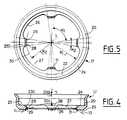
- la figure 4 montre, vu en coupe par un plan incluant l'axe de rotation du corps par rapport au support, tel que le plan I-I de la figure 2, un premier mode de réalisation des moyens de repérage du positionnement du kératotome par rapport à la cornée.
- la figure 5 montre une vue de ces moyens en plan, par exemple dans le sens repéré par la flèche II à la figure 1.
- les figures 6 et 7 montrent, respectivement, en une vue en plan dans le sens repéré par la flèche II à la figure 1 et en coupe par un plan repéré en IX-IX à la figure 2 et incluant l'axe de rotation du corps, des moyens de repérage d'un axe d'astigmatisme.
- la figure 8 montre, en une vue dans un sens repéré par une flèche X à la figure 1, un détail des moyens micrométriques d'écartement entre des zones respectives du porte-couteau et du corps, pour permettre le réglage de la valeur du décalage de la pointe d'un couteau par rapport à l'axe de rotation relative du corps et du support.
- la figure 9 montre une vue de détail d'un couteau, dans un sens repéré par une flèche XI à la figure 1.
- la figure 10 montre, en une vue dans un sens repéré par une flèche XII à la figure 1, un détail des moyens pour déplacer de façon réglée un couteau en translation suivant sa direction propre, c'est-à-dire pour régler la valeur de la saillie que la pointe du couteau forme à l'extérieur du support, par rapport à la surface de référence, en position de coupe.
- la figure 11 montre un extrait de la figure 1, à plus grande échelle.
- Figure 1 shows a keratotome according to the invention, half in side elevation and half in section through a plane marked in II in the figure and including the relative axis of rotation of the inner body and the outer support, which axis coincides with the visual axis when using the keratotome.
- Figure 2 shows a partial view of the keratotome, in plan, that is to say as it appears opposite its part of the foot, parallel to the relative axis of rotation of the inner body and the outer support , in a direction marked by an arrow II in FIG. 1; for reasons of clarity, we have omitted in this figure the knives, the knife holders as well as the detail of the means for driving the body in rotation relative to the support.
- Figure 3 shows a view, in section through two half-planes including the relative axis of rotation of the inner body and the outer body and identified in III-III in Figure 2, the ring carried by the support, adjustable in angular position around the relative axis of rotation of the body and the support, and itself carrying the stops provided on the support to limit the rotation of the body.
- FIG. 4 shows, seen in section through a plane including the axis of rotation of the body relative to the support, such as plane II of FIG. 2, a first embodiment of the means for locating the positioning of the keratotome relative to the cornea.
- FIG. 5 shows a plan view of these means, for example in the direction indicated by the arrow II in FIG. 1.
- Figures 6 and 7 show, respectively, in a plan view in the direction marked by arrow II in Figure 1 and in section through a plane marked in IX-IX in Figure 2 and including the axis of rotation of the body , means for locating an axis of astigmatism.
- Figure 8 shows, in a view in a direction marked by an arrow X in Figure 1, a detail of micrometric means of spacing between respective zones of the knife holder and of the body, to allow the adjustment of the value of the offset of the point of a knife relative to the relative axis of rotation of the body and the support.
- FIG. 9 shows a detailed view of a knife, in a direction marked by an arrow XI in FIG. 1.
- FIG. 10 shows, in a view in a direction marked by an arrow XII in FIG. 1, a detail of the means for moving a knife in a controlled manner in translation in its own direction, that is to say for adjusting the value of the projection that the point of the knife forms on the outside of the support, relative to the reference surface, in the cutting position.
- Figure 11 shows an extract from Figure 1, on a larger scale.
Le kératotome illustré est un type comportant deux couteaux, mais il est bien entendu que l'on ne sortirait pas du cadre de la présente invention en réalisant conformément aux enseignements de celle-ci un kératotome comportant un seul couteau, ou éventuellement plus de deux couteaux.The keratotome illustrated is a type comprising two knives, but it is understood that it would not go beyond the scope of the present invention to produce, in accordance with the teachings thereof, a keratotome comprising a single knife, or possibly more than two knives .
En vue de sa préhension manuelle par le chirurgien et de son positionnement sur la face antérieure 1 de la cornée 2 à inciser, le kératotome illustré 3 comporte un support extérieur 4 présentant la forme générale d'une paroi tubulaire tronconique de révolution autour d'un axe 5 et enveloppant un corps intérieur ou chariot 6 présentant également la forme d'une paroi tubulaire de révolution autour de l'axe 5, montée tournante dans le support autour de cet axe 5 à l'exclusion de toute autre possibilité de déplacement relatif.In view of its manual gripping by the surgeon and of its positioning on the
Le support extérieur 4 diverge d'une partie de pied 7 destinée à s'appliquer sur la face antérieure 1 de la cornée 2 à inciser, autour de l'emplacement des incisions à réaliser, jusqu'à une partie de tête 8 destinée à sa préhension par la main non dominante du chirurgien.The
La paroi constituant le support extérieur 4 dans sa partie de pied 7 comporte une cavité 9 annulaire, de révolution autour de l'axe 5 et s'ouvrant dans la partie de pied 7 par une fente annulaire 10, délimitée par deux portées 11, 12 annulaires de révolution autour de l'axe 5 et se situant sur une même surface de référence 13. La surface de référence 13 est choisie de façon à correspondre à la majorité des faces antérieures 1 de cornée 2. Un effet d'aspiration vers l'intérieur de la cavité 9, par la fente 10, résulte du raccordement de cette cavité 9 à des moyens 14 permettant d'y établir une dépression, raccordés à la cavité 9 par un embout 15 de raccordement de celle-ci, extérieur au support 4, et par un conduit souple 16.The wall constituting the
De préférence, la portée 11 la plus proche de l'axe 5 est constituée par une pièce annulaire 17 rapportée à rotation sur le support 4, dans une gorge 18 annulaire de ce dernier, tournée vers l'axe 5. Cette gorge est délimitée par deux pièces démontables afin de permettre de changer la pièce 17 illustrée aux figures 1, 4, 5Preferably, the
La pièce 17 ou toute autre pièce susceptible de leur être substituée, comporte une jupe périphérique 20, 21, annulaire de révolution autour de l'axe 5 avec une forme étroitement complémentaire de celle de la gorge 18. A l'intérieur de la jupe 20 ou 21, la pièce 17 présente une paroi délimitée par une face 22, 23 plane, supérieure, perpendiculaire à l'axe 5 et présentant, sur l'autre face, des formes déterminées affleurant la surface de référence 13.The
Ainsi, comme le montrent plus particulièrement les figures 4 et 5, la pièce 17 présente une paroi transversale en forme de couronne 24, limitée par deux faces planes 22, 25, et un chant annulaire 26. Quatre zones 27 disposées suivant un même cylindre géométrique non référencé, de rayon R₁, de longueur angulaire α₁ proche de 90°, alternent avec quatre zones 28 de longueur angulaire α₂ de l'ordre de quelques degrés. Chacune de ces zones 28 porte sur sa face 25 une arête 29 en arc de cercle 30 de rayon R₂ inférieur à R₁ et en pratique supérieur à celui de la zone claire de la cornée.Thus, as shown more particularly in Figures 4 and 5, the
Les quatre arêtes 29 permettent un positionnement précis du kératome 3 sur la cornée 2, préalablement pourvue d'un marquage circulaire centré sur l'axe visuel. Les quatre arêtes 29 affleurent la surface de référence 13 pour constituer ensemble la portée 11 de contact avec la face antérieure 1 de la cornée 2, sur le marquage circulaire de même rayon que le cercle 30.The four
La pièce 17 peut comporter en outre, en saillie sur sa face 25 à proximité immédiate de chaque arête 29, un groupe de dents 31 empêchant un glissement du kératome sur la face antérieure 1 de la cornée ; la pièce 17 est par ailleurs entièrement située en retrait par rapport à la surface de référence 13.The
Le support extérieur 4 comporte une autre gorge 39 annulaire intérieure dans sa zone de tête 8 avec un fond 40 de diamètre aussi grand que possible compte-tenu des dimensions de la partie de tête 8. La gorge 39 comporte deux flancs plans 41, 42, perpendiculaires à l'axe 5. Les flancs 41 et 42 débouchent sur des faces respectives 43, 44 du support extérieur 4, lesquelles sont cylindriques de révolution autour de l'axe 5 vers lequel elles sont tournées, par l'intermédiaire d'un rebord 45, pour le flanc 41 et directement pour le flanc 42. Sous la face 43, le support 4 comporte une face 46 tronconique convergeant vers sa partie de pied 7. Le support extérieur 4 est limité en partie supérieure par une face 47 plane.The
Le support 4 qui vient d'être décrit est avantageusement constitué de plusieurs pièces assemblées mutuellement par des moyens permettant de les dissocier à volonté, de telle sorte qu'on puisse le nettoyer aisément. En particulier, les parties de tête 8 et de pied 7, bien que mutuellement solidaires, sont dissociables à volonté au niveau de l'épaulement 45 de façon à permettre l'accès à des moyens de réglage qui seront décrits plus loin.The
Le support extérieur 4 coopère par la gorge 39 et la face 44 avec le corps intérieur 6 pour assurer le guidage de ce dernier en rotation autour de l'axe 5 sans aucune possiblité de mouvement relatif.The
A cet effet, le corps 6 porte une face 48 cylindrique de diamètre légèrement inférieur à celui de la face 44, en regard de laquelle elle est placée sans contact mutuel. Cette face 48 porte deux épaulements 49 et 50 qui forment une saillie radiale et qui sont placés respectivement en regard de la face 44 et en regard de la gorge 39, dans laquelle s'engage l'épaulement 50. L'épaulement 50 est délimité par des faces annulaires planes 51, 52 et par une face périphérique extérieure 53 cylindrique glissant sur le fond 40 de la gorge 39.To this end, the
Les faces 52 et 51 de l'épaulement 50 sont en appui respectivement contre les flancs 41 et 42 par l'intermédiaire d'un roulement à billes 55, 56. L'épaulement 49 est délimité par des faces annulaires planes 57, 58 et une face 59 de forme générale cylindrique de révolution autour de l'axe 5, avec un diamètre sensiblement identique à celui de la face 44 de façon à établir par contact glissant un autre guidage du corps 6 et du support 4 en rotation autour de l'axe 5. La face 59 est creusée de dents d'engrenage 60 régulièrement réparties angulairement autour de l'axe 5 de façon à coopérer avec des moyens manuels d'entraînement 61 de conception connue, par exemple décrite dans le document EP 0 047 190, qui coopèrent avec les dents d'engrenage 60 du corps 6 par l'intermédiaire d'un pignon 62 monté à rotation sur le support 4 autour d'un axe 63 parallèle à l'axe 5, lequel pignon 62 traverse localement la face 44 du support 4, vers l'axe 5, par une lumière 64 de cette face 44.The faces 52 and 51 of the
On remarquera que du fait des dispositions qui viennent d'être décrites et lorsque l'on sépare la partie de pied 7 de la partie de tête 8 au niveau de l'épaulement 45, le corps 6 du kératotome 3 reste assemblé à la partie de tête 8, qui porte également les moyens d'entraînement manuel 61.It will be noted that because of the arrangements which have just been described and when the
Par des faces 65, 66, 67 délimitant un épaulement intérieur, le corps 6 porte de façon solidaire mais de préférence amovible en vue des opérations de maintenance, deux chapes identiques 68, diamétralement opposées. Chacune de ces chapes 68 assure le montage tourillonnant d'un porte-couteau respectif 70 autour d'un axe d'articulation 69 par rapport au corps 6. Les deux axes 69 sont situés perpendiculairement à un même plan 205 incluant l'axe 5 et se confondant avec le plan repéré en I-I à la figure 2 et symétriquement l'un de l'autre par rapport à un plan 204, incluant également l'axe 5 mais perpendiculaire au plan 205, et sont situés à la fois aussi loin que possible de l'axe 5 et aussi près que possible de la face 58 de l'épaulement 49 du corps 6, c'est-à-dire de la face 47 de la partie de tête 48 du support 4 afin d'être aussi éloignés que possible de la partie de pied 7 de celui-ci.By faces 65, 66, 67 delimiting an internal shoulder, the
Dans le plan 205 incluant l'axe 5 et perpendiculaire aux axes 69, le porte-couteau 70 présente une direction moyenne propre 71 perpendiculaire à l'axe 69. On peut ainsi l'orienter par rapport à l'axe 5 en faisant pivoter le porte-couteau 70 autour de l'axe 69, par rapport à la chape 68 et au corps 6. En pratique, la direction moyenne propre 71 de chaque porte-couteau 70 coupe la surface de référence 13 à l'intérieur d'une zone annulaire 76 de celle-ci, de révolution autour de l'axe 5 avec un rayon minimal R₃ inférieur au rayon R₂ précité mais néanmoins supérieur à celui de la zone claire d'une cornée 2.In the
Des moyens sont prévus pour immobiliser de façon réglée chaque porte-couteau 70 en rotation autour de l'axe 69.Means are provided for immobilizing in a controlled manner each
A cet effet, chaque chape 68 présente une zone 72 formant une saillie approximativement parallèle à l'axe 5, par rapport à la face 52 de l'épaulement 50 vers la partie de pied 7 du support 4, cette zone 72 étant en retrait vers l'intérieur du support 4 par rapport à la surface de référence 13 et n'entrant en contact avec aucune partie du support 4 bien que cette zone 72 soit située plus loin de l'axe 5 que le porte-couteau 70.For this purpose, each
Par cette zone 72, la chape 68 porte une couronne 73, tournante autour d'un axe 74 mais sans possibilité de translation suivant cet axe 74 ; l'axe 74 est situé dans le plan 205, décalé par rapport à l'axe 69, vers la partie de pied 7 du support 4, et perpendiculaire à la direction propre 71 du porte-couteau 70, par rapport auquel cet axe 74 est fixe.Through this
La couronne 73 est ainsi disposée du côté de la zone 72 opposé au côté de celle-ci tournée vers l'axe 5, dans une position dégagée par la partie de pied 7 du support 4 lorsque celle-ci est séparée de la partie de tête 8 de façon à permettre alors sa rotation manuelle. Comme le montre la figure 8, cette couronne 73 porte des graduations 80 visibles lorsque la partie de pied 7 est ainsi séparée de la partie de tête 8, ces graduations étant exprimées par exemple en mm, et correspondant à des diamètres d'incision. De façon complémentaire, la zone 72 de la chape 68 ou le porte-couteau 70 lui-même porte un repère 75, par exemple sous la forme d'un simple trait.The
Vers l'axe 74, comme le montre la figure 11, la couronne 73 présente un taraudage micrométrique 77, en prise avec une vis coaxiale 78 montée sur le porte-couteau 70 de façon solidaire. En tournant la couronne 73, on peut régler l'écartement entre le porte-couteau 70 et la zone 72 de la chape 68 au niveau de l'axe 74, c'est-à-dire régler l'orientation de la direction propre 71 par rapport à l'axe 5 et, en particulier, l'écartement ou décalage R₄, intermédiaire entre R₂ et R₃, séparant de l'axe 5 le point 79 d'intersection de cette direction propre 71 avec la surface de référence 13, dans les limites de la zone 76 de la surface de référence 13. Cet écartement ou décalage R₄ détermine un rayon d'incision.Towards the
Pour autoriser un tel mouvement, le montage de la couronne 73 sur la zone 72 de la chape 68 s'effectue, comme le montre la figure 11, par engagement d'une gorge 254, annulaire de révolution autour de l'axe 74, que présente la couronne 73, dans une glissière 81 de la zone 72 de la chape 68. Cette glissière 81 présente la forme d'une fourche s'ouvrant vers la partie de pied 7 et comportant deux bras 250 symétriques par rapport au plan 205 et s'engageant dans la gorge 254 de part et d'autre de l'axe 74. Chacun des bras 250 se dédouble lui-même, vers la partie de pied 7, en deux branches 251, 252 qui sont situées de part et d'autre d'un plan 253 approximativement perpendiculaire à l'axe 74 et prennent appui de façon antagoniste, parallèlement à cet axe 74, dans la gorge 254. Les branches 252 les plus proches de l'axe 5 sont rigides mais les branches 251 les plus éloignées de l'axe 5 sont dimensionnées, de façon aisément déterminable par un Homme du métier et en fonction du matériau constitutif de la chape 68, convenablement choisi à cet effet par cet Homme du métier, de façon à présenter une élasticité telle que les deux branches 251 et 252 soient en permanence retenues en précontrainte, dans le sens d'un rapprochement mutuel dans la gorge 254 ; un tel montage, tout en empêchant tout déplacement de la couronne 73 parallèlement à l'axe 74 par rapport à la zone 72 de la chape 68, et plus précisément par rapport aux branches 252 les plus rigides des bras 250, autorise un débattement de la couronne 73 par rapport à l'axe 69 ainsi qu'un basculement de la couronne 73 par rapport à la zone 72 de la chape 68.To authorize such a movement, the mounting of the
Chaque porte-couteau 70 présente une forme générale tubulaire, de révolution autour de sa direction propre 71, et délimite intérieurement un canal 208 recevant, en coulissement suivant cette direction propre 71, un couteau 82 s'étendant de façon rectiligne d'une pointe extrême 83 en forme de lancette, comme le montre la figure 9, tournée vers la partie de pied 7, à une extrémité de manoeuvre 84 placée en saillie hors du corps 6 et du support 4 au niveau de la partie de tête 8 de ce dernier. Des méplats respectifs 85, 86 du couteau 82 et du porte-couteau 70 empêchent une rotation autour de la direction propre 71, qui constitue également pour le couteau 82 une direction moyenne propre passant par sa pointe extrême 83.Each
Au niveau de son extrémité 84, chaque couteau 82 coopère avec le porte-couteau 70 correspondant par l'intermédiaire de moyens 87 permettant de déplacer de façon réglée le couteau 82, en translation suivant la direction propre 71, par rapport au porte-couteau 70, entre deux positions limites :
- une position de repos dans laquelle le couteau est illustré à la figure 1 et dans laquelle il est placé en retrait vers l'intérieur du corps 6 et du
support 4, dans un sens 202 de la direction propre 71, par rapport à la surface de référence 13 que lapointe 83 affleure toutefois, - une position de coupe que l'on a schématisée en trait mixte à la figure 1 et dans laquelle la
pointe 83 forme une saillie à l'extérieur du corps 6 et dusupport 4, dansun sens 203 opposé au sens 202, par rapport à la surface de référence 13 que le couteau 82 coupe alors en respectant le décalage réglé R₄ par rapport à l'axe 5, l'amplitude de cette saillie pouvant être réglée par action sur les moyens 87, indépendamment pour l'un et l'autre des couteaux 82.
- a rest position in which the knife is illustrated in FIG. 1 and in which it is set back towards the interior of the
body 6 and of thesupport 4, in adirection 202 in theproper direction 71, with respect to the surface ofreference 13 which thepoint 83 is however flush with, - a cutting position which is shown diagrammatically in phantom in Figure 1 and in which the
tip 83 forms a projection outside thebody 6 and thesupport 4, in adirection 203 opposite to thedirection 202, with respect to thereference surface 13 which theknife 82 then cuts while respecting the set offset R₄ with respect to theaxis 5, the amplitude of this projection being adjustable by action on themeans 87, independently for one and the other of theknives 82.
A cet effet, par son extrémité 84, chaque couteau 82 porte un bouton de réglage 88, placé en saillie hors du porte-couteau 70 à l'opposé de la pointe 83. Ce bouton 88 est monté tournant autour de la direction propre 71 par rapport au couteau 82 et solidaire en translation par rapport au porte-couteau 70 suivant la direction propre 71. Le bouton 88 porte des graduations 89 exprimées par exemple en dixièmes de millimètres, ces graduations correspondant à la saillie que la pointe 83 du couteau 82 forme par rapport à la surface de référence 13 en position de coupe.To this end, by its
Le bouton 88 porte un filetage 90 par lequel il est en prise avec un taraudage 91 d'un fourreau 92 monté en translation suivant la direction propre 71 aussi bien par rapport au bouton de réglage 88 que par rapport au porte-couteau 70. Le fourreau 92 enveloppe ainsi localement le bouton 88, au niveau de son filetage 90 ainsi que, localement, un tronçon 93 du couteau 82 situé entre la partie de tête 8 du support 4 et l'extrémité 84.The
Le fourreau 92 peut se déplacer en translation suivant la direction propre 71 par rapport au porte-couteau 70, de même que par rapport au bouton 88 et au couteau 92, mais il est calé en rotation sur le porte-couteau 70, par un clavetage 94, dans une zone extrême 95 du porte-couteau 70 enveloppant le fourreau 92, en saillie hors du support 4 par la partie de tête 8 de celui-ci, dans le sens 202, entre l'extrémité 84 du couteau 82 et l'axe 69.The
Pour coopérer avec les graduations 89 du bouton de réglage 88, le fourreau 92 porte, sur une couronne 96 entourant le bouton de manoeuvre 88, un repère 97 par exemple sous la forme d'un trait radial en référence à la direction propre 71, comme le montre la figure 10, ce qui permet d'assurer un repérage de la position angulaire relative du bouton de réglage 88 et du fourreau 92, c'est-à-dire également du porte-couteau 70, autour de la direction propre 71, c'est-à-dire de permettre d'afficher une valeur réglée de la saillie que la pointe 83 du couteau 82 forme par rapport à la surface de référence 13 lorsque le couteau 82 est en position de coupe.To cooperate with the
Par sa zone extrême 95, le porte-couteau 70 enveloppe extérieurement le fourreau 92 et un ressort de compression 98 interposé entre-eux à ce niveau, précontraint suivant la direction propre 71, tend à déplacer élastiquement le fourreau 92 à la translation suivant la direction propre 71, par rapport au porte-couteau 70, vers l'axe 69 et vers l'intérieur du support 4, c'est-à-dire dans le sens 203.By its
Le fourreau 92 présente extérieurement, entre la zone extrême 95 du porte-couteau 70 et le bouton de réglage 88, un épaulement annulaire 99. Cet épaulement 99 est tourné dans le sens 203 vers l'axe 69 et s'appuie vers ce dernier sur un épaulement opposé 100 intérieur d'un bouton de déclenchement 101 enveloppant le fourreau 92 en dehors de la zone extrême 95 du porte-couteau 70, avec possibilité de rotation du bouton de déclenchement 101 autour de la direction propre 71 par rapport au fourreau 92 ainsi que de translation relative suivant cette direction propre 71, toutefois dans les limites autorisées par le contact mutuel des épaulements 99 et 100, d'une part, et la compression maximale du ressort 98, d'autre part.The
L'un vers l'autre, le bouton de déclenchement 101 et le porte-couteau 70, dans sa zone 95, présentent eux-mêmes des moyens de butée mutuelle suivant la direction propre 71, autorisant deux positions relatives stables, suivnt cette direction propre 71, selon la position angulaire relative autour de cette direction propre.One towards the other, the
Plus précisément, vers la zone extrême 95 du porte-couteau 70, dans le sens 203, le bouton de déclenchement 101 présente une alternance de nervures 102 et de rainures 103 radiales, les nervures 102 présentant dans le ses 203 des méplats extrêmes 104 perpendiculaires à la direction propre 71. La zone extrême 95 du porte-couteau 70 présente quant à elle vers le bouton de déclenchement 101, dans le sens 202, une alternance de nervures 105 et de rainures 106 radiales complémentaires des rainures 103 et des nervures 102, les nervures 105 présentant, dans le sens 202, des méplats extrêmes 107 plans, perpendiculaires à la direction propre 71.More specifically, towards the
Le couteau 82, le porte-couteau 70, le bouton de réglage 88, le fourreau 92, le bouton de déclenchement 101 sont dimensionnés, d'une façon aisément déterminable par un Homme du métier, de telle sorte que :
- en plaçant les méplats respectifs 104
et 107 des nervures 102et 105 en appui mutuel suivant la direction propre 71 et en orientant le bouton de réglage 88 de telle sorte que le chiffre 0 s'affiche sur lesgraduations 89 en regard du repère 97 du fourreau 92, onplace le couteau 82 dans une position telle quesa pointe 83 soit placée en retrait par rapport à la surface de référence 13, d'une valeur telle que si, ensuite, on place par rotation du bouton de déclenchement 101 les nervures 102 en coïncidence avec les rainures 106 et les nervures 105 en coïncidence avec les nervures 103, il s'ensuive par action du ressort 98 une translation d'ensemble du bouton de déclenchement 101, du fourreau 92, du bouton de réglage 88 et du couteau 82, dans le sens 203, par rapport au porte-couteau 70 avec une amplitude telle que lapointe 83 vienne affleurer la surface de référence 13, comme on l'a illustré à la figure 1 ; - et que, en plaçant à nouveau le bouton de déclenchement 101 en appui sur la
zone extrême 95 du porte-couteau 70 par l'intermédiaire des méplats 104et 107, et si l'on affiche alors au moyen du bouton de réglage 88, au moyen desgraduations 89 et du repère 97, la saillie maximale envisagée pourla pointe 83 du couteau 82 par rapport à la surface de référence 93, lapointe 83 reste placée en retrait par rapport à la surface de référence 13 jusqu'à ce que l'on applique au bouton de déclenchement 101 une rotation telle que ses nervures et rainures correspondent respectivement avec les rainures et nervures de lazone extrême 95 du porte-couteau 70,le ressort 98 provoquant alors une translation brusque du bouton de déclenchement 101, du fourreau 92, du bouton de réglage 88 et du couteau 82, dans le sens 203, par rapport au porte-couteau 90, jusqu'à provoquer une saillie de lapointe 83 du couteau 82, par rapport à la surface de référence 13, d'une valeur correspondant à la valeur affichée au moyen du bouton de réglage 88.
- by placing the
respective flats ribs proper direction 71 and by orienting theadjustment button 88 so that the number 0 is displayed on thegraduations 89 opposite themarker 97 of thesheath 92, theknife 82 is placed in a position such that itstip 83 is set back relative to thereference surface 13, by a value such that if, then, theribs 102 are placed by rotation of thetrigger button 101 in coincidence with thegrooves 106 and theribs 105 in coincidence with theribs 103, it follows by the action of thespring 98 an overall translation of thetrigger button 101, thesheath 92, theadjustment button 88 and theknife 82 , indirection 203, relative to theknife holder 70 with an amplitude such that thetip 83 comes flush with thereference surface 13, as illustrated in FIG. 1; - and that, once again placing the
trigger button 101 in abutment on theend zone 95 of theknife holder 70 by means of theflats adjustment button 88, at by means of thegraduations 89 and of themark 97, the maximum projection envisaged for thepoint 83 of theknife 82 with respect to thereference surface 93, thepoint 83 remains placed in withdrawal with respect to thereference surface 13 until the 'is applied to the trigger button 101 a rotation such that its ribs and grooves correspond respectively with the grooves and ribs of theend zone 95 of theknife holder 70, thespring 98 then causing a sudden translation of thetrigger button 101, thesheath 92, of theadjustment knob 88 and of theknife 82, in thedirection 203, relative to theknife holder 90, until causing thepoint 83 of theknife 82, relative to thereference surface 13, to protrude a value corresponded nt to the value displayed using theadjustment button 88.
Ainsi, le chirurgien peut, préalablement à la pose du kératotome 3 sur la face antérieure 1 de la cornée 2, pratiquer au moyen de la couronne 73 un réglage du décalage R₄ de l'intersection de la direction propre 71 avec la surface de référence 13, par rapport à l'axe 5, indépendamment pour l'un et l'autre des couteaux 82 et alors que la partie de tête 7 est démontée de la partie de corps 8 puis, après avoir remonté ces deux parties l'une sur l'autre, afficher au moyen du bouton de réglage 88 une profondeur d'incision pour chaque couteau 82, indépendamment, alors que ces couteaux 82 restent dans une position de repos, en retrait par rapport à la surface de référence 13. Après la mise en place sur la face antérieure de la cornée 2, en coïncidence de l'axe 5 avec l'axe visuel et après immobilisation du kératotome 3 par application d'une dépression dans la cavité 9, ou grâce à l'ancrage des dents 31 sur la cornée, le chirurgien peut en tournant le bouton de déclenchement 101 provoquer un passage brusque de chaque couteau 82 dans une position de saillie pré-réglée par rapport à la surface de référence 13, c'est-à-dire provoquer directement une pénétration de chaque couteau 82 sur une profondeur pré-réglée dans la cornée 2.Thus, the surgeon can, prior to placement of the
Ensuite, en agissant sur les moyens d'entraînement 61, le chirurgien provoque une rotation du corps 6 par rapport au support 4, ce qui se traduit par une rotation identique des deux couteaux 82 autour de l'axe visuel par rapport à la cornée 2, c'est-à-dire par la réalisation d'incisions arciformes de même longueur angulaire.Then, by acting on the drive means 61, the surgeon causes a rotation of the
Pour permettre au chirurgien de contrôler, et de préférence de pré-régler, d'une part la position angulaire des incisions arciformes et d'autre part leur amplitude angulaire, le kératotome 3 selon l'invention présente des moyens de détermination de la position angulaire relative du support et du corps, autour de l'axe 5, lesquels moyens 108 vont être décrits à présent en référence aux figures 1, 2, 3 dans un mode de réalisation préféré.To allow the surgeon to control, and preferably to pre-adjust, on the one hand the angular position of the arcuate incisions and on the other hand their angular amplitude, the
Dans ce mode de réalisation, ces moyens 108 comportent notamment, dans la partie de tête 8 du support 4, une bague coaxiale 109 qui en est solidaire, avec possibilité de réglage de sa position angulaire.In this embodiment, these
A cet effet, la bague 109, réalisée en acier à ressort ou analogue présente une face périphérique extérieure 110 cylindrique d'un diamètre qui, lorsque cette bague est assemblée au support 4, est identique à celui de la face 44, que la bague 109 épouse par sa face 110 de la proximité immédiate de la face 58 de l'épaulement 49 du corps 6 jusqu'à la face 47. La bague 109 forme en outre une saillie au dessus de la face 47. A un niveau correspondant sensiblement à celui de la face 47, la face 110 est creusée d'une gorge annulaire continue 111 par laquelle elle s'emboîte sur une nervure annulaire, continue 112 que le support 4 présente, en saillie vers l'axe 5, par rapport à sa face 44, au raccordement de cette dernière avec la face 47.For this purpose, the
La bague 109 est axialement limitée par une face annulaire plane 113, et par une arête circulaire 114 se raccordant à la face 113, par une face périphérique intérieure 116 pour l'essentiel tronconique de révolution autour de l'axe 5, sauf de façon localisée comme il apparaîtra plus loin.The
La bague 109 présente une discontinuité sous forme d'une fente 117, ce qui la rend élastiquement compressible radialement, et elle est montée par rapport au support 4 en butée, par sa face 110, contre la face 44 du support 4 qui lui offre ainsi une portée de friction.The
Toutefois, une sollicitation manuelle volontaire de la bague 109, en direction circonférentielle, dans le sens d'une fermeture de la fente 117, permet de réduire le diamètre de la face 110 de la bague 109, et par conséquent de provoquer à volonté la rotation de celle-ci autour de l'axe 5 par rapport au support 4 avant de la solidariser à nouveau avec celui-ci en relâchant ladite sollicitation manuelle.However, a voluntary manual stress on the
En vue de permettre cette sollicitation, la bague 109 présente de part et d'autre de la fente 17, dans sa partie en saillie par rapport à la face 47 du support 4, des moyens de préhension manuelle sous la forme de deux encoches 118 laissant subsister entre elles et la fente 17 un ergot 119 offrant aux doigts du chirurgien un appui vers la fente 117.In order to allow this stress, the
Dans une zone périphérique intérieure 120 ne comprenant pas la fente 117 et présentant en une longueur angulaire α₃ de 180°, la face périphérique intérieure tronconique 116 ne se raccorde pas directement à la face 113 de la bague 109, et ce raccordement s'effectue par l'intermédiaire d'une face périphérique intérieure 121 cylindrique de révolution autour de l'axe 5, vers lequel cette face 121 est tournée. A ses deux extrémités, si l'on considère une direction circonférentielle centrée sur l'axe 5, la face 121 se raccorde par un épaulement de butée 122 à la face périphérique intérieure tronconique 116.In an interior
Complémentairement, le corps 6 porte réglable, en saillie parallèlement à l'axe 5 sur la face 58 de l'épaulement 49, dans une zone de cette face 58 qui reste dégagée par la bague 109, deux plots de butée 124 placés en regard de la zone périphérique intérieure 120 de la bague 109 et aptes à venir buter circonférentiellement contre l'un ou l'autre des épaulements 122, dans l'un ou l'autre sens 206, 207 de rotation du corps 6 par rapport au support 4. Ces plots de butée 124 sont symétriques par rapport au plan 204 dont ils sont respectivement décalés de moins de 90°, respectivement dans le sens 206 et dans le sens 207.In addition, the
A cet effet, le corps 6 présente dans la face 58 une pluralité de trous borgnes 125 identiques, cylindriques de révolution autour d'axes respectifs 126 équirépartis angulairement autour de l'axe 5 et équidistants de celui-ci, et chacun de ces trous borgnes 125 peut recevoir l'un des plots de butée 124 ; dasn l'exemple préféré illustré, les trous borgnes 125 sont ainsi prévus au nombre de 13, répartis selon un pas angulaire α₄ de 10° sur un développement angulaire total de 120°, symétriquement par rapport au plan 204 ; par exemple, chaque trou 125 est taraudé et chaque plot 124 est pourvu d'une tige filetée 127 apte à se visser dans un trou 125.To this end, the
En solidarisant les deux plots 124 avec le corps 6 dans des positions angulaires convenablement choisies en référence à l'axe 5, symétriques par rapport au plan 204, et dans la mesure où chaque plot 124 est propre à venir buter circonférentiellement contre l'un des épaulements 122 dans un sens 206, 207 de rotation du corps 6 par rapport au support 4, on peut fixer des limites de rotation du corps 6 autour de l'axe 5 par rapport au support 4 avec d'une part prédétermination de l'amplitude de rotation relative entre les orientations limites par réglage de la position angulaire des plots 124 sur le corps 6 et d'autre part, réglage du positionnement angulaire de ces orientations limites en référence au support 4 par réglage de la position angulaire des épaulements de butée 122 de la bague 109 par rapport à celui-ci.By joining the two
A cet égard, les trous borgnes 125 jouent sur le corps 6 le rôle de graduation permettant de repérer visuellement la position angulaire de celui-ci par rapport à la bague 109, c'est-à-dire par rapport au support 4, en coopération avec les épaulements de butée 122 de la bague 109. De préférence, à chacun de ces trous borgnes 125 est en outre associée une graduation 123 qui, dans l'exemple illustré, est exprimée en valeur de décalage angulaire de l'axe 126 du trou borgne 125 considéré, par rapport au plan 205, autour de l'axe 5, exprimée en degrés d'angle. Ainsi, un trou borgne 125 dont l'axe 126 est situé dans le plan 204 porte à titre de graduation 123 le nombre 90 et les trous borgnes 125 qui se succèdent à partir de ce trou borgne 125, respectivement de part et d'autre du plan 204, portent les nombres 80, 70, 60, 50, 40, 30 respectivement.In this regard, the
Avant de provoquer la sortie brusque des couteaux 82 de leur position de repos à leur position de coupe et après avoir fixé le kératotome 3 en position convenable sur la face antérieure 1 de la cornée 2, il suffit au chirurgien d'amener, par action sur les moyens 61, le corps 6 dans une orientation dans laquelle il est en butée par l'un des plots 124 contre l'épaulement 122 correspondant puis, après avoir provoqué la sortie brusque des couteaux, de provoquer la rotation du corps 6 par rapport au support 4 jusqu'à ce que l'autre plot 124 vienne en butée contre l'autre épaulement 122, pour être assuré de réaliser des incisions d'une amplitude angulaire prédéterminée, et dans des positions également prédéterminées.Before causing the
Pour faciliter les réglages préalables, le corps 6 porte également, de préférence, des moyens 128 de repérage d'un axe d'astigmatisme, par exemple sous une forme apte à être solidarisée avec le corps 6, de façon amovible, en même temps que celui des plots de butée 124 qui est décalé dans le sens 206 par rapport au plan 204 dans l'exemple illustré, par exemple par pincement entre ce plot et la face 58 de l'épaulement 49 du corps 1, de sorte que ces moyens de repérage se situent suivant un même plan incluant l'axe 5 et l'axe commun 126 de ce plot 124 et du trou 125 le recevant ; ce plan coïncide avec le plan repéré en IX-IX à la figure 2.To facilitate the prior adjustments, the
On a précisément illustré aux figures 2, 6, 7 des moyens 128 de repérage d'un axe d'astigmatisme ainsi conçus ; ces moyens se présentent sous la forme d'une aiguille 129 qui, comme le montre la figure 7, converge vers l'axe 5 dans un sens allant de la partie de tête 8 vers la partie de pied 7, tout en restant intégralement en retrait par rapport à la surface de référence 13.FIGS. 2, 6, 7 have precisely illustrated means 128 for locating an axis of astigmatism thus designed; these means are in the form of a
Vers l'axe 5 et vers cette surface de référence 13, l'aiguille 129 présente un coude terminé par une extrémité pointue libre 130 qui aboutit à l'axe 5 au voisinage de la surface 13 de la référence de sorte que cette pointe constitue le repère à superposer à la marque de l'axe visuel du patient alors qu'à l'opposé, elle est emprisonnée de façon solidaire, par une autre extrémité 131, dans une pièce intermédiaire de montage 132 présentant une forme propre à épouser localement les faces 65, 67, 66 du corps 6 ainsi que la face 58 de l'épaulement 49 de celui-ci, et ceci par une zone fourchue 133 propre à s'intercaler entre le plot 124 respectif et la face 58, autour de la tige 127 de ce plot 124.Towards
Dans ces conditions, le réglage de la longueur angulaire de chaque incision et sa position angulaire peuvent s'effectuer de la façon suivante, la profondeur et le diamètre d'incision étant supposés réglés et chaque couteau étant supposé occuper la position de repos :
- on détermine le développement angulaire de chacune des incisions à réaliser, en référence à l'axe visuel,
- on visse, dans les deux trous 125 dont les
graduations 123 correspondent à la moitié du développement angulaire d'incision choisi,un plot 124 respectif en fixant les moyens 128 au moyen duplot 124 décalé dans le sens 206 parrapport au plan 104, - on fait tourner la bague 109 par
rapport au support 4 jusqu'à amener encontact le plot 124 muni des moyens 128 et l'épaulement de butée 122 associé, sans faire tourner le corps 6 parrapport au support 4, - après avoir placé convenablement et immobilisé le kératotome sur la cornée, notamment en ayant placé en coincidence la pointe 13O et la marque de l'axe visuel du patient, en orientant les moyens 61 de manoeuvre manuelle d'une façon commode pour le chirurgien on fait éventuellement tourner conjointement la bague 109 et le corps 6 par
rapport au support 4 en maintenant le contact précité duplot 124 muni des moyens 128 et de l'épaulement de butée 122 associé, pour amener l'aiguille 129 en coïncidence avec l'axe d'astigmatisme, repéré au préalable sur laface antérieure 1 de la cornée 2, - on provoque le passage des couteaux à leur position de coupe et, sans faire tourner la bague 109 par
rapport au support 4, on fait tourner le corps 6 par rapport à celui-ci dans le sens 207 jusqu'à ce que l'autre desplots 124 vienne au contact de l'autre des épaulements 122, ce qui réalise les incisions désirées, - on rétracte les couteaux vers leur position de repos et on sépare le kératotome de la cornée.
- the angular development of each of the incisions to be made is determined, with reference to the visual axis,
- a
respective stud 124 is screwed into the twoholes 125, thegraduations 123 of which correspond to half of the angular development of the chosen incision. fixing themeans 128 by means of thestud 124 offset in thedirection 206 relative to theplane 104, - the
ring 109 is rotated relative to thesupport 4 until contacting thestud 124 provided with themeans 128 and the associatedabutment shoulder 122, without rotating thebody 6 relative to thesupport 4, - after having appropriately placed and immobilized the keratotome on the cornea, in particular by having placed in coincidence the tip 13O and the mark of the visual axis of the patient, by orienting the
means 61 of manual operation in a manner convenient for the surgeon, optionally jointly turning thering 109 and thebody 6 relative to thesupport 4 while maintaining the aforementioned contact of thestud 124 provided with themeans 128 and the associatedabutment shoulder 122, to bring theneedle 129 into coincidence with the axis d astigmatism, previously identified on theanterior surface 1 of thecornea 2, - the knives are brought into their cutting position and, without rotating the
ring 109 relative to thesupport 4, thebody 6 is rotated relative to the latter in thedirection 207 until the other of thepads 124 come into contact with the other of theshoulders 122, which makes the desired incisions, - the knives are retracted to their rest position and the keratotome is separated from the cornea.
Dans l'exemple illustré notamment à la figure 2, on réalise ainsi simultanément deux incisions arciformes d'un développement angulaire respectif de 120°C, équi-réparti de part et d'autre de l'axe d'astigmatisme, en plaçant les deux plots 124 dans les trous borgnes 125 repérés par les nombres 60 en tant que graduations 123 et, dans son mode de réalisation décrit, le kératotome selon l'invention, permet de réaliser ainsi une gamme d'incisions dont le développement angulaire respectif varie par pas de 20° entre 60°, auquel cas les plots 124 doivent être placés dans les trous borgnes 125 repérés par le nombre 30, et 180°, auquel cas un plot unique 124 doit être placé dans le trou borgne 125 repéré par le nombre 90, mais d'autre modes de variation des développements angulaires des incisions réalisables au moyen d'un kératotome selon l'invention de même que d'autres valeurs limites de ces développements angulaires pourraient être choisis sans que l'on sorte pour autant du cadre de la présente invention.In the example illustrated in particular in FIG. 2, two arcuate incisions are thus made simultaneously with a respective angular development of 120 ° C., equi-distributed on either side of the axis of astigmatism, by placing the two
Claims (9)
- A keratotome for making an incision in a cornea, and comprising, for this purpose:
an envelope-forming tubular outer support (4) having a determined axis (5) and including, for application against a cornea (2), an annular base portion (7) that is circularly symmetrical about the axis (5) of the support (4) and that defines a reference geometrical surface (13) determined by the shape presented by the cornea (2) when the support (4) has its base portion (7) pressed thereagainst;
a tubular inner body (6) disposed coaxially inside the support and set back towards the inside of the support (4) relative to the reference surface (13);
guide means (39, 50, 55, 56) for guiding the body in rotation about the axis (5) relative to the support (4);
drive means (61) for driving the body (6) in rotation about the axis (5) relative to the support (4);
a blade (82) disposed inside the body (6) and extending along a longitudinal direction (71), the blade having a sharp tip (83) in a determined direction (203) relative to its longitudinal direction (71); and
means (68, 70, 86) for providing a connection between the blade (82) and the body (6), said means including means (87) for displacing the blade (82) in controlled manner in translation along its longitudinal axis (71) relative to the body (6) between a rest position, in which it is set back towards the inside of the support (4) relative to the reference surface (13), and in which the tip (83) is directed towards said reference surface (13), and in a cutting position where the tip (83) projects outside from the support (4) relative to the reference surface (13), in a manner that is offset relative to the axis (5) of the support (4);
characterized in that in order to perform arcuate incisions of determined angular position and of determined angular length, the support (4) and the body (6) have determining means (108) for determining their relative angular position which include abutments (122, 124) defining two limiting relative angular positions between the support (4) and the body (6) and carried respectively by the support (4) and by the body (6). - A keratotome according to claim 1, characterized in that the determining means (108) include graduation forming means (122, 123) forming graduations for marking angular position relative to the support and the body (6) and carried respectively by the support (4) and by the body (6).
- A keratotome according to claim 1 or claim 2, characterized in that the support (4) carries a coaxial ring (109) that is angularly adjustable in position and that carries abutments (122) that are integral therewith, the abutments being offset by 180° from each other, and in that the body (6) carries abutments (124) that are angularly adjustable independently.
- A keratotome according to claim 3, characterized in that the body (6) is integral with one of the abutments (122) of the means (128) for marking the axis of astigmatism.
- A keratotome according to claim 3 or 4, characterized in that said ring (109) is opened by a radial gap (117), which is elastically compressible radially and in centrifugal radial abutment against a coaxial annular bearing surface (44) of the support (4) under prestress such that it is temporarily secured to the support (4) by friction, but with the gap (117) nevertheless remaining open, and in that it has grasping means (119) on respective sides of said radial gap (117) for the purpose of enabling manual force to be applied circumferentially in such a direction as to close the gap (117).
- A keratotome according to any one of claims 1 to 7, characterized in that it further includes:
another blade (82) angularly offset by 180° relative to the first blade and disposed inside the body (6) along its own axial direction (71) and having its own sharp tip (83) in a determined direction (203) along its longitudinal direction (71); and
link means (68, 70) between the other blade (82) and the body (6) themselves including means (87) for displacing the other blade (82) in adjustable manner in translation along its own longitudinal direction (71) relative to the body (6) between a rest position in which it is set back towards the inside of the support (4) relative to the reference surface (13), and in which its tip (83) points towards said reference surface (13), and a cutting position in which the tip (83) projects out from the support (4) relative to the reference surface (13) so as to be offset relative to the axis (5) of the support (4). - A keratotome according to claim 6, characterized in that the means (87) for displacing each of the blades (82) in adjustable manner in translation along its own longitudinal direction (71) comprise:
means (88, 89, 92, 97) for displaying the adjusted value of said projection while the blade (82) remains in its rest position; and
means (92, 98, 101) for causing the blade (82) to move voluntarily and suddenly from its rest position to its cutting position. - A keratotome according to claim 7, characterized in that the means (87) for displacing each blade (82) in adjustable manner in translation along its own longitudinal direction (71) comprise:
an adjustment knob (88) placed to project beyond the blade carrier (70) away from the tip (83) and mounted to rotate about said longitudinal direction (71) relative to the blade carrier (70), and constrained to move in translation with the blade (82) along said longitudinal direction (71);
a sleeve (92) mounted to move in translation relative to the adjustment knob (88) and relative to the blade carrier (70), along said longitudinal direction (71), and constrained to rotate with the blade carrier (70) about said longitudinal direction (71), and having a transverse shoulder (99) extending transversely relative to said longitudinal direction (71) and facing in a direction (203) going from the rest position towards the cutting position;
threaded connection means (90, 91) between the adjustment knob (88) and the sleeve (92);
micrometer graduations (89, 97) for identifying the relative angular position of the adjustment knob (88) and of the sleeve (92) about said longitudinal direction (71), and constituting said means (88, 89, 92, 97) for displaying the adjusted value of said projection;
means (98) for resiliently urging the sleeve (92) in translation relative to the blade carrier (70) along said longitudinal direction (71) in a direction (203) going from the rest position towards the cutting position;
a trip knob (101) mounted to rotate relative to the adjustment knob (88), to the sleeve (92), and to the blade carrier (70), and having a shoulder (100) extending transversely relative to said longitudinal direction (71) and facing in a direction (202) going from the cutting position towards the rest position, and bearing against said transverse shoulder (99) of the sleeve (92); and
mutual abutment means (102, 103, 105, 106) between the trip knob (101) and the blade carrier (70) in said longitudinal direction (71), comprising on the trip knob (101) alternating radial ribs (102) and grooves (103) about said longitudinal direction (71) and facing in a direction (203) going from the rest position towards the cutting position, and on the blade carrier (70) alternating radial grooves (106) and ribs (105) about said longitudinal direction (71), and facing in a direction (202) going from the cutting position towards the rest position, and respectively complementary to the ribs (102) and the grooves (103) of the trip knob (101), said ribs and grooves (102, 103, 105, 106) being shaped so that mutual thrust between the trip knob (101) and the blade carrier (70) by means of said ribs (102, 105) as by engagement of said ribs (102, 105) in said grooves (103, 106) is stable. - A keratotome according to any one of claims 6 to 8, characterized in that it includes means (73, 78) for adjusting the offset value (R₄) of the tip (83) of each blade (82) relative to the axis (5) of the support (4) in the cutting position, which means comprise:
hinge means (68) for hinging the blade carrier (70) to the body (6) about a determined hinge axis (69) offset relative to the axis (5) of the support (4) and set back towards the inside of the support (4) relative to the reference surface (13), and perpendicular to the longitudinal direction (71) of the blade (82) and to a plane (205) including the axis (5) of the support (4); and
means (73, 78) for locking the blade carrier (70) relative to the body (6) in adjustable manner in rotation about the hinge axis.
Applications Claiming Priority (3)
| Application Number | Priority Date | Filing Date | Title |
|---|---|---|---|
| FR9004722 | 1990-04-12 | ||
| FR9004722AFR2660859B1 (en) | 1990-04-12 | 1990-04-12 | KERATOTOME FOR THE MAKING OF ARCIFORM INCISIONS. |
| PCT/FR1991/000300WO1991016023A1 (en) | 1990-04-12 | 1991-04-11 | Keratome for making arc-shaped incisions |
Publications (2)
| Publication Number | Publication Date |
|---|---|
| EP0525098A1 EP0525098A1 (en) | 1993-02-03 |
| EP0525098B1true EP0525098B1 (en) | 1994-09-21 |
Family
ID=9395713
Family Applications (1)
| Application Number | Title | Priority Date | Filing Date |
|---|---|---|---|
| EP91908771AExpired - LifetimeEP0525098B1 (en) | 1990-04-12 | 1991-04-11 | Keratome for making arc-shaped incisions |
Country Status (5)
| Country | Link |
|---|---|
| US (1) | US5441511A (en) |
| EP (1) | EP0525098B1 (en) |
| DE (1) | DE69104196T2 (en) |
| FR (1) | FR2660859B1 (en) |
| WO (1) | WO1991016023A1 (en) |
Families Citing this family (57)
| Publication number | Priority date | Publication date | Assignee | Title |
|---|---|---|---|---|
| US6450641B2 (en) | 1992-06-02 | 2002-09-17 | Lasersight Technologies, Inc. | Method of corneal analysis using a checkered placido apparatus |
| US6467906B1 (en) | 1992-08-10 | 2002-10-22 | Noel Ami Alpins | System for evaluating and correcting irregular astigmatism in the eye of a patient |
| US5749867A (en)* | 1992-08-10 | 1998-05-12 | Alpins; Noel Ami | Method of analysing astigmatism and apparatus for performing corneal surgery |
| US6086579A (en)* | 1992-08-10 | 2000-07-11 | Alpins; Noel Ami | Method of analyzing astigmatism and apparatus for performing corneal surgery |
| AU663930B2 (en)* | 1992-08-10 | 1995-10-26 | Noel Ami Alpins | Method of analysing astigmatism and apparatus for performing corneal surgery |
| USRE37504E1 (en) | 1992-12-03 | 2002-01-08 | Lasersight Technologies, Inc. | Ophthalmic surgery method using non-contact scanning laser |
| US6716210B2 (en) | 1992-12-03 | 2004-04-06 | Lasersight Technologies, Inc. | Refractive surgical laser apparatus and method |
| US5486188A (en)* | 1993-11-15 | 1996-01-23 | Smith; Alan D. | Keratoscopic surgical instrument for making radial and arcuate corneal incisions |
| EP0776966B1 (en)* | 1995-12-02 | 2002-09-11 | The Procter & Gamble Company | Liquid bleaching compositions packaged in spray-type dispenser and a process for pretreating fabrics therewith |
| US7166117B2 (en) | 1996-02-07 | 2007-01-23 | Hellenkamp Johann F | Automatic surgical device and control assembly for cutting a cornea |
| US5997529A (en) | 1996-10-28 | 1999-12-07 | Lasersight Technologies, Inc. | Compound astigmatic myopia or hyperopia correction by laser ablation |
| US6210169B1 (en) | 1997-01-31 | 2001-04-03 | Lasersight Technologies, Inc. | Device and method for simulating ophthalmic surgery |
| US6126668A (en)* | 1997-04-25 | 2000-10-03 | Innovative Optics, Inc. | Microkeratome |
| JP3097600B2 (en)* | 1997-05-30 | 2000-10-10 | 日本電気株式会社 | Stratum corneum puncture device |
| US6007202A (en) | 1997-10-23 | 1999-12-28 | Lasersight Technologies, Inc. | Eye illumination system and method |
| US6132424A (en) | 1998-03-13 | 2000-10-17 | Lasersight Technologies Inc. | Smooth and uniform laser ablation apparatus and method |
| US6409718B1 (en) | 1998-02-03 | 2002-06-25 | Lasersight Technologies, Inc. | Device and method for correcting astigmatism by laser ablation |
| US6582445B1 (en)* | 1998-03-11 | 2003-06-24 | Visx, Incorporated | Trephine for lamellar keratectomy |
| US5938674A (en)* | 1998-03-23 | 1999-08-17 | Terry; Clifford M. | Astigmatism reducing cutter |
| EP1173790A2 (en) | 1999-03-01 | 2002-01-23 | Boston Innovative Optics, Inc. | System and method for increasing the depth of focus of the human eye |
| US6497701B2 (en) | 1999-04-30 | 2002-12-24 | Visx, Incorporated | Method and system for ablating surfaces with partially overlapping craters having consistent curvature |
| US6254619B1 (en) | 1999-12-28 | 2001-07-03 | Antoine Garabet | Microkeratome |
| US6436113B1 (en)* | 2000-09-18 | 2002-08-20 | Thomas A. Burba | Eye positioner |
| FR2818119B1 (en)* | 2000-12-14 | 2003-09-05 | Khalil Hanna | BIT FOR TAKING A CORNEOSCLERAL CAP FROM A DONOR'S EYE |
| KR101080473B1 (en) | 2003-04-07 | 2011-11-04 | 테크노라스 게엠베하 옵탈몰로지쉐 시스템 | Microkeratome, Microkeratome Fixation Ring and Microkeratome Cutting Head |
| US7628810B2 (en) | 2003-05-28 | 2009-12-08 | Acufocus, Inc. | Mask configured to maintain nutrient transport without producing visible diffraction patterns |
| US20050046794A1 (en) | 2003-06-17 | 2005-03-03 | Silvestrini Thomas A. | Method and apparatus for aligning a mask with the visual axis of an eye |
| US20070083221A1 (en)* | 2005-10-12 | 2007-04-12 | Sismed, Llc | Precision trephine |
| US20070083087A1 (en)* | 2005-10-12 | 2007-04-12 | Sismed, Llc | Fixator with membrane |
| US9545338B2 (en) | 2006-01-20 | 2017-01-17 | Lensar, Llc. | System and method for improving the accommodative amplitude and increasing the refractive power of the human lens with a laser |
| US9889043B2 (en) | 2006-01-20 | 2018-02-13 | Lensar, Inc. | System and apparatus for delivering a laser beam to the lens of an eye |
| US10842675B2 (en) | 2006-01-20 | 2020-11-24 | Lensar, Inc. | System and method for treating the structure of the human lens with a laser |
| US8262646B2 (en)* | 2006-01-20 | 2012-09-11 | Lensar, Inc. | System and method for providing the shaped structural weakening of the human lens with a laser |
| US20080147083A1 (en)* | 2006-11-09 | 2008-06-19 | Vold Steven D | Method and device for fixation of ophthalmic tissue |
| US8500723B2 (en) | 2008-07-25 | 2013-08-06 | Lensar, Inc. | Liquid filled index matching device for ophthalmic laser procedures |
| US8480659B2 (en) | 2008-07-25 | 2013-07-09 | Lensar, Inc. | Method and system for removal and replacement of lens material from the lens of an eye |
| US8758332B2 (en) | 2009-07-24 | 2014-06-24 | Lensar, Inc. | Laser system and method for performing and sealing corneal incisions in the eye |
| US8382745B2 (en) | 2009-07-24 | 2013-02-26 | Lensar, Inc. | Laser system and method for astigmatic corrections in association with cataract treatment |
| CN102647954B (en) | 2009-07-24 | 2016-02-03 | 能斯雅有限公司 | A kind ofly provide the system and method for laser irradiation pattern for eye lens |
| US8617146B2 (en) | 2009-07-24 | 2013-12-31 | Lensar, Inc. | Laser system and method for correction of induced astigmatism |
| JP2013500086A (en) | 2009-07-24 | 2013-01-07 | レンサー, インク. | System and method for performing a procedure using LADAR on an eye lens |
| CA2770735C (en) | 2009-08-13 | 2017-07-18 | Acufocus, Inc. | Masked intraocular implants and lenses |
| WO2011020074A1 (en) | 2009-08-13 | 2011-02-17 | Acufocus, Inc. | Corneal inlay with nutrient transport structures |
| US10004593B2 (en) | 2009-08-13 | 2018-06-26 | Acufocus, Inc. | Intraocular lens with elastic mask |
| WO2011094678A1 (en) | 2010-02-01 | 2011-08-04 | Lensar, Inc. | Purkinjie image-based alignment of suction ring in ophthalmic applications |
| USD695408S1 (en) | 2010-10-15 | 2013-12-10 | Lensar, Inc. | Laser system for treatment of the eye |
| USD694890S1 (en) | 2010-10-15 | 2013-12-03 | Lensar, Inc. | Laser system for treatment of the eye |
| EP4205633A1 (en) | 2010-10-15 | 2023-07-05 | Lensar, Inc. | System and method of scan controlled illumination of structures within an eye |
| US10463541B2 (en)* | 2011-03-25 | 2019-11-05 | Lensar, Inc. | System and method for correcting astigmatism using multiple paired arcuate laser generated corneal incisions |
| JP6046160B2 (en) | 2011-12-02 | 2016-12-14 | アキュフォーカス・インコーポレーテッド | Ophthalmic mask with selective spectral transmission |
| US9204962B2 (en) | 2013-03-13 | 2015-12-08 | Acufocus, Inc. | In situ adjustable optical mask |
| US9427922B2 (en) | 2013-03-14 | 2016-08-30 | Acufocus, Inc. | Process for manufacturing an intraocular lens with an embedded mask |
| US9943403B2 (en) | 2014-11-19 | 2018-04-17 | Acufocus, Inc. | Fracturable mask for treating presbyopia |
| ES2972581T3 (en) | 2015-10-05 | 2024-06-13 | Acufocus Inc | Intraocular lens molding methods |
| KR102407311B1 (en) | 2015-11-24 | 2022-06-10 | 아큐포커스, 인크. | Toroidal eyelet intraocular lens with extended depth of focus |
| EP3790508A4 (en) | 2018-05-09 | 2022-02-09 | AcuFocus, Inc. | INTRAOCULAR IMPLANT WITH REMOVABLE OPTICS |
| CN113749850B (en)* | 2021-10-09 | 2023-09-22 | 王禹 | Cornea astigmatism loosening aid |
Family Cites Families (5)
| Publication number | Priority date | Publication date | Assignee | Title |
|---|---|---|---|---|
| DE2741663C2 (en)* | 1976-09-17 | 1986-05-07 | The University Of Melbourne, Parkville, Victoria | Cornea cutter |
| US4608977A (en)* | 1979-08-29 | 1986-09-02 | Brown Russell A | System using computed tomography as for selective body treatment |
| FR2489141A1 (en)* | 1980-09-03 | 1982-03-05 | Sevifra | SURGICAL APPARATUS FOR PRECISE CUTTING OF THE CORNEA |
| US4423728A (en)* | 1982-02-26 | 1984-01-03 | Lieberman David M | Cam-guided trephine |
| US4648400A (en)* | 1985-05-06 | 1987-03-10 | Rts Laboratories, Inc. | Ophthalmic surgery system |
- 1990
- 1990-04-12FRFR9004722Apatent/FR2660859B1/ennot_activeExpired - Lifetime
- 1991
- 1991-04-11EPEP91908771Apatent/EP0525098B1/ennot_activeExpired - Lifetime
- 1991-04-11DEDE69104196Tpatent/DE69104196T2/ennot_activeExpired - Fee Related
- 1991-04-11USUS07/934,740patent/US5441511A/ennot_activeExpired - Lifetime
- 1991-04-11WOPCT/FR1991/000300patent/WO1991016023A1/enactiveIP Right Grant
Also Published As
| Publication number | Publication date |
|---|---|
| DE69104196T2 (en) | 1995-05-11 |
| DE69104196D1 (en) | 1994-10-27 |
| FR2660859B1 (en) | 1992-07-10 |
| EP0525098A1 (en) | 1993-02-03 |
| WO1991016023A1 (en) | 1991-10-31 |
| US5441511A (en) | 1995-08-15 |
| FR2660859A1 (en) | 1991-10-18 |
Similar Documents
| Publication | Publication Date | Title |
|---|---|---|
| EP0525098B1 (en) | Keratome for making arc-shaped incisions | |
| EP0147318B1 (en) | Surgical apparatus for radial keratotomy | |
| EP0404689B1 (en) | Lens for epikeratophakia and keratotome intended for the creation of an incision for implantation of such a lens | |
| EP0047190B1 (en) | Surgical device for the accurate removal of the cornea | |
| EP2449985B1 (en) | Orthopaedic reamer for bone preparation, in particular for glenoïd preparation | |
| EP1885267A1 (en) | Joint fusion apparatus for the ankle-type joint and arthrodetic pin for use in said apparatus | |
| EP0749732A1 (en) | Intraocular lens system to correct ocular anisotropy | |
| FR2524296A1 (en) | DEVICE FOR TARGETING THE DISTAL END OF A PIN | |
| EP2068726B1 (en) | Sighting ancillary device for resurfacing of the femoral head | |
| CA3129470A1 (en) | Guide device for a medical needle | |
| EP2699385B1 (en) | Ophthalmic-lens holder | |
| WO2019179988A1 (en) | Assembly comprising an intervertebral implant of the tlif type and an instrument for the placement of said implant | |
| CA2578805A1 (en) | Boring head | |
| EP4142635B1 (en) | Mechanism for handling a surgical instrument | |
| FR2693368A1 (en) | Surgical cutting instrument for ocular surgery, e.g. keratoplasty - comprises cylindrical sleeve supporting blade unit with extended cutting edge, with intermediate locking ring securing components together | |
| EP1457159B1 (en) | Drill guide for positioning a glenoid implant | |
| FR2595243A1 (en) | Knife for surgery of the anterior segment of the eye | |
| WO2016055958A1 (en) | Instrument that can be used when fitting a shoulder prosthesis or a prosthetic element on a humerus | |
| FR2631545A1 (en) | Applicator for epicorneal implantation of flexible (soft) lenses | |
| EP4255355B1 (en) | Device for gripping a prosthetic element such as a cup, and method for using a gripping device as trial insert | |
| WO1997046353A1 (en) | Handtool such as scissors with pivoting gripper member and spring return means | |
| WO2025172486A1 (en) | Trephine for corneal graft cutting | |
| FR2818119A1 (en) | Corneal trepan surgical instrument has housing with support foot to engage eye and cutter rotor to remove tissue disc | |
| FR3028173A1 (en) | INSTRUMENT FOR ASSEMBLING AN INSERT IN A CUPULE AND TOGETHER FOR PLACING A HIP PROSTHESIS ON A PATIENT | |
| FR2921285A1 (en) | Ophthalmic lens trimming method, involves carrying out edge retrieving process by machining rear foot on portion of surface of foot using grinding wheel whose work generator is inclined with respect to blocking axis |
Legal Events
| Date | Code | Title | Description |
|---|---|---|---|
| PUAI | Public reference made under article 153(3) epc to a published international application that has entered the european phase | Free format text:ORIGINAL CODE: 0009012 | |
| 17P | Request for examination filed | Effective date:19921006 | |
| AK | Designated contracting states | Kind code of ref document:A1 Designated state(s):DE GB IT | |
| 17Q | First examination report despatched | Effective date:19930804 | |
| GRAA | (expected) grant | Free format text:ORIGINAL CODE: 0009210 | |
| AK | Designated contracting states | Kind code of ref document:B1 Designated state(s):DE GB IT | |
| GBT | Gb: translation of ep patent filed (gb section 77(6)(a)/1977) | Effective date:19940928 | |
| REF | Corresponds to: | Ref document number:69104196 Country of ref document:DE Date of ref document:19941027 | |
| ITF | It: translation for a ep patent filed | ||
| PLBE | No opposition filed within time limit | Free format text:ORIGINAL CODE: 0009261 | |
| STAA | Information on the status of an ep patent application or granted ep patent | Free format text:STATUS: NO OPPOSITION FILED WITHIN TIME LIMIT | |
| 26N | No opposition filed | ||
| REG | Reference to a national code | Ref country code:GB Ref legal event code:IF02 | |
| PGFP | Annual fee paid to national office [announced via postgrant information from national office to epo] | Ref country code:GB Payment date:20080331 Year of fee payment:18 | |
| PGFP | Annual fee paid to national office [announced via postgrant information from national office to epo] | Ref country code:DE Payment date:20080530 Year of fee payment:18 | |
| PGFP | Annual fee paid to national office [announced via postgrant information from national office to epo] | Ref country code:IT Payment date:20080418 Year of fee payment:18 | |
| GBPC | Gb: european patent ceased through non-payment of renewal fee | Effective date:20090411 | |
| PG25 | Lapsed in a contracting state [announced via postgrant information from national office to epo] | Ref country code:DE Free format text:LAPSE BECAUSE OF NON-PAYMENT OF DUE FEES Effective date:20091103 | |
| PG25 | Lapsed in a contracting state [announced via postgrant information from national office to epo] | Ref country code:GB Free format text:LAPSE BECAUSE OF NON-PAYMENT OF DUE FEES Effective date:20090411 | |
| PG25 | Lapsed in a contracting state [announced via postgrant information from national office to epo] | Ref country code:IT Free format text:LAPSE BECAUSE OF NON-PAYMENT OF DUE FEES Effective date:20090411 |