EP0524247B1 - Apparatus and method for controlling data flow between a computer and memory devices - Google Patents
Apparatus and method for controlling data flow between a computer and memory devicesDownload PDFInfo
- Publication number
- EP0524247B1 EP0524247B1EP91907931AEP91907931AEP0524247B1EP 0524247 B1EP0524247 B1EP 0524247B1EP 91907931 AEP91907931 AEP 91907931AEP 91907931 AEP91907931 AEP 91907931AEP 0524247 B1EP0524247 B1EP 0524247B1
- Authority
- EP
- European Patent Office
- Prior art keywords
- level controller
- level
- memory devices
- state
- controller
- Prior art date
- Legal status (The legal status is an assumption and is not a legal conclusion. Google has not performed a legal analysis and makes no representation as to the accuracy of the status listed.)
- Expired - Lifetime
Links
Images


Classifications
- G—PHYSICS
- G06—COMPUTING OR CALCULATING; COUNTING
- G06F—ELECTRIC DIGITAL DATA PROCESSING
- G06F11/00—Error detection; Error correction; Monitoring
- G06F11/07—Responding to the occurrence of a fault, e.g. fault tolerance
- G06F11/16—Error detection or correction of the data by redundancy in hardware
- G06F11/20—Error detection or correction of the data by redundancy in hardware using active fault-masking, e.g. by switching out faulty elements or by switching in spare elements
- G06F11/2053—Error detection or correction of the data by redundancy in hardware using active fault-masking, e.g. by switching out faulty elements or by switching in spare elements where persistent mass storage functionality or persistent mass storage control functionality is redundant
- G06F11/2089—Redundant storage control functionality
- G06F11/2092—Techniques of failing over between control units
- G—PHYSICS
- G06—COMPUTING OR CALCULATING; COUNTING
- G06F—ELECTRIC DIGITAL DATA PROCESSING
- G06F11/00—Error detection; Error correction; Monitoring
- G06F11/07—Responding to the occurrence of a fault, e.g. fault tolerance
- G06F11/08—Error detection or correction by redundancy in data representation, e.g. by using checking codes
- G06F11/10—Adding special bits or symbols to the coded information, e.g. parity check, casting out 9's or 11's
- G06F11/1076—Parity data used in redundant arrays of independent storages, e.g. in RAID systems
- G—PHYSICS
- G11—INFORMATION STORAGE
- G11B—INFORMATION STORAGE BASED ON RELATIVE MOVEMENT BETWEEN RECORD CARRIER AND TRANSDUCER
- G11B20/00—Signal processing not specific to the method of recording or reproducing; Circuits therefor
- G11B20/10—Digital recording or reproducing
- G11B20/18—Error detection or correction; Testing, e.g. of drop-outs
- G11B20/1833—Error detection or correction; Testing, e.g. of drop-outs by adding special lists or symbols to the coded information
- G—PHYSICS
- G06—COMPUTING OR CALCULATING; COUNTING
- G06F—ELECTRIC DIGITAL DATA PROCESSING
- G06F11/00—Error detection; Error correction; Monitoring
- G06F11/07—Responding to the occurrence of a fault, e.g. fault tolerance
- G06F11/0703—Error or fault processing not based on redundancy, i.e. by taking additional measures to deal with the error or fault not making use of redundancy in operation, in hardware, or in data representation
- G06F11/0751—Error or fault detection not based on redundancy
- G06F11/0754—Error or fault detection not based on redundancy by exceeding limits
- G06F11/0757—Error or fault detection not based on redundancy by exceeding limits by exceeding a time limit, i.e. time-out, e.g. watchdogs
- G—PHYSICS
- G06—COMPUTING OR CALCULATING; COUNTING
- G06F—ELECTRIC DIGITAL DATA PROCESSING
- G06F11/00—Error detection; Error correction; Monitoring
- G06F11/07—Responding to the occurrence of a fault, e.g. fault tolerance
- G06F11/16—Error detection or correction of the data by redundancy in hardware
- G06F11/20—Error detection or correction of the data by redundancy in hardware using active fault-masking, e.g. by switching out faulty elements or by switching in spare elements
- G06F11/202—Error detection or correction of the data by redundancy in hardware using active fault-masking, e.g. by switching out faulty elements or by switching in spare elements where processing functionality is redundant
- G06F11/2023—Failover techniques
- G06F11/2033—Failover techniques switching over of hardware resources
Definitions
- the present inventionrelates generally to input/output communication. More particularly, the invention is a method and apparatus for controlling data flow through a group of first level memory device controllers and a group of second level memory device controllers such that if one of the second level memory device controllers experiences a failure, rerouting of data can be accomplished transparently to the computer.
- An I/O systemis known from reference US - A-4,697,232.
- EP-A-0 010 211proposes a computer system which uses two or more I/O exchanges between peripheral controllers and serial peripheral units, such as disk files, disk packs and tape drives and provides redundant communication paths that can be made available for communication between N controllers and M peripheral units. All peripheral controllers and units are connected to each exchange. Each controller and unit may be manually assigned to a certain exchange. In the case of two exchanges. if a certain one fails due to a loss of power, all peripheral units are automatically assigned to the other exchange.
- Systems for controlling data flow between a computer and a group of memory devicestypically include at least one controller situated between the computer and the memory devices.
- the controlleris used to handle data communication between the computer and the memory devices.
- Computer systemscan be configured to include a group of memory devices. Each such controller is assigned a particular group of memory devices. As data is output from the computer a particular controller will handle that data and store it in one of the memory devices under its control. Through the use of these controllers and the physical configuration of the memory devices, the logical configuration of the memory devices can be altered and set to the needs of the user.
- the computerIn the case where one of the controllers experiences a failure, the computer must take action to isolate the failed controller and to switch the memory devices formally under the failed controller's control to a properly functioning other controller. The switching requires the computer to perform a number of operations. First, it must isolate the failed controller. This means that the path between the computer and the failed controller must be broken and all data flow directed to the failed controller must be redirected to a working controller.
- a plurality of first level controllersare each connected to the computer. Connected to the other side of the first level controllers is a set of second level controllers. Each first level controller can route data to any one of the second level controllers. Communication buses tie together the second level controllers and the first level controllers can also communicate between themselves.
- the systemis configured such that the second level controllers are grouped in pairs. This configuration provides each second level controller with a single associated back-up controller. This configuration provides for efficient rerouting procedures for the flow of data to the disk drives. For ease of understanding, the specification will describe the system configured with pairs of second level controllers. Of course, it should be understood that the second level controllers could be configured in groups of three or other groupings.
- a switching functionis implemented to connect each of the second level controllers to a group of disk drives.
- the computerneed not get involved with the rerouting of data to the disk drives. Instead, the first level controllers and the properly working second level controller can handle the failure without the involvement of the computer. This allows the logical configuration of the disk drives to remain constant from the perspective of the computer despite a change in the physical configuration.
- the first typeis a complete failure.
- the second level controllerstops communicating with the first level controllers and the other second level controller.
- the first level controllersare informed of the failure by the properly working second level controller or may recognize this failure when trying to route data to the failed second level controller. In either case, the first level controller will switch data paths from the failed second level controller to a properly functioning second level controller. Once this rerouted path has been established, the properly functioning second level controller issues a command to the malfunctioning second level controller to release control of its disk drives. The properly functioning second level controller then assumes control of these disk drive arrays.
- the second type of failureis a controlled failure where the failed controller can continue to communicate with the rest of the system.
- the partner second level controlleris informed of the malfunction.
- the properly functioning second level controllerthen informs the first level controllers to switch data paths to the functioning second level controller.
- the malfunctioning second level controllerreleases its control of the disk drives and the functioning second level controller assumes control.
- the properly functioning second level controllerchecks and, if necessary, corrects data written to the drives by the malfunctioning second level controller.
- a further aspect of the present inventionis a SCSI bus switching function which permits the second level controllers to release and assume control of the disk drives.
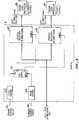
- Fig. 1is a diagram showing an overall view of the input/output system associated with a computer 10 for accessing disk drives.
- Computer 10has its input/output ports connected to a pair of first level controllers 12A and 12B.
- first level controllers 12A and 12BIn a second controller level a pair of second level controllers 14A and 14B are shown connected to first level controllers 12A and 12B.
- the lines between second level controllers 14 and first level controller 12represent data buses through which data flows.
- the dashed line between second level controller 14A and second level controller 14Brepresents a communication line through which the devices communicate with each other.
- Second level controllers 14are each connected to a group of disk drive arrays 18A-18M through switches 16A-16M.
- Disk drives 20are arranged in a manner so that each second level controller 14 is primarily responsible for one group of disk drive arrays. As shown in Fig. 1, second level controller 14A may be primarily responsible for three drives in each disk drive array 18A-18M. Similarly, second level controller 14B may be primarily responsible for the remaining three disk drives in disk drive arrays 18A-18M. Second level controllers 14 are secondarily responsible for the disk drives primarily controlled by the partner second level controller. In the particular arrangement shown in Fig. 1, second level controller 14A may be primarily responsible for the left three drives (i.e. 20A1-20A3) in each disk drive array 18 and secondarily responsible for the right three disk drives (i.e. 20A4-20A6) in disk drive arrays 18. Second level controller 14B is primarily responsible for the right three disk drives (i.e. 20A4-20A6) in each disk drive array 18 and secondarily responsible for the left three disk drives (i.e. 20A1-20A3) in disk drive arrays 18.
- Each second level controller 14contains a second level controller recovery system (CRS) 22.
- CRS 22is a portion of software code which manages the communication between second level controllers 14 and first level controllers 12.
- CRS 22is typically implemented as a state machine which is in the form of microcode or sequencing logic for moving second level controller 14 from state to state (described below). State changes are triggered as different events occur and messages are sent between the various components of the system.
- Fig. 2is a block diagram showing a more detailed illustration of the interconnections between second level controllers 14A and 14B and the disk drives. For simplicity, only a single disk drive array 18A is shown. More disk drive arrays may be included in the system as shown in Fig. 1.
- Second level controller 14Ahas a primary control/sense line 50A for controlling its primary set of disk drives.
- An alternate control/sense line 52Acontrols an alternate set of disk drives.
- second level controller 14Bhas a corresponding set of control/sense lines.
- Data buses 54A (second level controller 14A) and 54B (second level controller 14B)carry the data to and from disk drives 20. These data buses are typically in the form of a SCSI bus.
- a set of switches 16A-16Mare used to grant control of the disk drives to a particular second level controller.
- second level controller 14Ahas primary responsibility for disk drives 20A1-20A3 and alternate control of disk drives 20A4-20A6.
- Second level controller 14Bhas primary control of disk drives 20A4-20A6 and alternate control of disk drives 20A1-20A3.
- Fig. 3is a more detailed illustration of one of the switches 16A-16M.
- a pair of pulse shapers 60A and 60Breceive the signals from the corresponding control/sense lines 50A and 52B shown in Fig. 2. Pulse shapers 60 clean up the signals which may have lost clarity as they were transmitted over the lines. Pulse shapers of this type are well known in the art.
- the clarified signals from pulse shapers 60are then fed to the set and reset pins of R/S latch 62.
- the Q and Q outputs of latch 62are sent to the enable lines of a pair of driver/receivers 64A and 64B.
- Driver/receivers 64A and 64Bare connected between the disk drives and second level controllers 14A and 14B. Depending upon whether primary control/sense line 52B or alternate control/sense line 50A is active, the appropriate second level controller will be in control at a particular time.
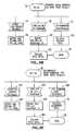
- Fig. 4is a state transition diagram showing the relationships between the various states of CRS 22 (Fig. 1) of a particular second level controller 14.
- Each second level controller 14must be in only one state at any particular point in time. Initially, assuming that the system is functioning properly and each second level controller 14 is primarily responsible for half of the disk drives in each disk drive array 18 and secondarily responsible for half of the disk drives in each disk drive array 18, second level controller 14 is in a PRIMARY STATE 26. While in PRIMARY STATE 26, two major events may happen to move a second level controller 14 from PRIMARY STATE 26 to another state. The first event, is the failure of the particular second level controller 14. If there is a failure, second level controller 14 shifts from PRIMARY STATE 26 to a NONE STATE 28. In the process of doing so, it will pass through RUN-DOWN-PRIMARIES-TO-NONE STATE 30.
- second level controller 14There are two types of failures which are possible in second level controller 14.
- the first type of failureis a controlled failure. Further, there are two types of controlled failures.
- the first type of controlled failureis a directed controlled failure. This is not actually a failure but instead an instruction input from an outside source instructing a particular second level controller to shut down.
- This instructionmay be received in second level controller 14 from one of the following sources: An operator, through computer 10; a console 19 through a port 24 (e.g. RS-232) on the first level controller; a diagnostic console 21 through a port 23 (e.g. RS-232) on the second level controller; or by software initiated during predictive maintenance.
- Such an instructionis issued in the case where diagnostic testing of a second level controller is to be conducted.
- the second level controllerfinishes up any instructions it is currently involved with and refuses to accept any further instructions.
- the second level controllereffects a "graceful" shut down by sending out messages to the partner second level controller that it will be shutting down.
- the second type of controlled failureis referred to as a moderate failure.
- the second level controllerrecognizes that it has a problem and can no longer function properly to provide services to the system. For example, the memory or drives associated with that second level controller may have malfunctioned. Therefore, even if the second level controller is properly functioning, it cannot adequately provide services to the system. It aborts any current instructions, refuses to accept any new instructions and sends a message to the partner second level controller that it is shutting down. In both controlled failures, the malfunctioning second level controller releases the set of disk drives over which it has primary control. These drives are then taken over by the partner second level controller.
- the second type of failureis a complete failure.
- the second level controllerbecomes inoperable and cannot send messages or "clean-up" its currently pending instructions by aborting them.
- the second level controllerhas lost its ability to serve the system. It is up to one of the first level controllers or the partner second level controller to recognize the problem.
- the partner second level controllerthen takes control of the drives primarily controlled by the malfunctioning second level controller. The routing through the malfunctioning second level controller is switched through the partner second level controller.
- Second level controllers 14 and first level controllers 12handle the rerouting independently by communicating the failure among themselves.
- second level controller 14Amoves from PRIMARY STATE 26 through a transition RUN-DOWN-PRIMARIES-TO-NONE STATE 30 to NONE STATE 28.
- second level controller 14Bmoves from PRIMARY STATE 26 to BOTH STATE 32.
- the basis for the change in state of each of second level controllers 14A and 14Bis the failure of second level controller 14A.
- disk drives 20A1-20A3are switched by switching functions 16A1-16A3 so that they are primarily controlled by second level controller 14B. Therefore, second level controller 14B is in BOTH STATE 32 indicating that it has control of the disk drives of both second level controllers. Second level controller 14A now controls none of the disk drives and is in NONE STATE 28. The transition state 30 determines which of several possible transition paths is used.
- second level controller 14Ais in NONE STATE 28 and second level controller 14B is in BOTH STATE 32 there are a number of options for transferring control of disk drives 20A1-20A6 once second level controller 14A has been repaired.
- second level controller 14A and second level controller 14Bcould each be shifted back to PRIMARY STATE 26. This is accomplished by second level controller 14A moving from NONE STATE 28 directly to PRIMARY STATE 26 along the preempt p line. Preempt p simply stands for "preempt primary" which means that second level controller 14A preempts its primary drives or takes control of them from second level controller 14B.
- second level controller 14Bmoves from BOTH STATE 32 through a transition RUN-DOWN-SECONDARIES-TO-PRIMARIES STATE 34 and then to PRIMARY STATE 26.
- a second alternativeis for second level controller 14A to move from NONE STATE 28 to SECONDARY STATE 36.
- second level controller 14Ais in control of its secondary disk drives 20A4-20A6.
- Second level controller 14Bconcurrently moves from BOTH STATE 32 through RUN-DOWN-PRIMARIES-TO-SECONDARIES STATE 38 and on to SECONDARY STATE 36.
- Second level controller 14Acontrols disk drives 20A4-20A6
- second level controller 14Bcontrols disk drives 20A1-20A3.
- a failing second level controller 14may move through RUN-DOWN-SECONDARIES-TO-NONE STATE 40 to NONE STATE 28. If this occurs, the properly functioning partner second level controller 14 moves from SECONDARY STATE 36 to BOTH STATE 32 so that computer 10 could access any one of disk drives 20A1-20A6. As in the previous example, if second level controller 14A were to fail it moves from SECONDARY STATE 36 through RUN-DOWN-SECONDARIES-TO-NONE STATE 40 and into NONE STATE 28. At the same time, properly functioning second level controller 14B moves from SECONDARY STATE 36 along the preempt b/p line into BOTH STATE 32. Preempt b/p stands for "preempt both/primaries.” In other words, all of the disk drives are preempted by the properly functioning second level controller.
- second level controller 14Ais in NONE STATE 28 and second level controller 14B is in BOTH STATE 32, it is possible for second level controller 14A to take control of both sets of disk drives. This is desirable if second level controller 14A were repaired and second level controller 14B failed. Second level controller 14A moves from NONE STATE 28 along the preempt b line to BOTH STATE 32. At the same time, second level controller 14B moves from BOTH STATE 32 through RUN-DOWN-BOTH-TO-NONE STATE 42 and into NONE STATE 28. At this point, second level controller 14A controls all disk drives 20A1-20A6 while second level controller 14B controls none of the disk drives.
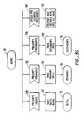
- second level controller 14may trigger the movement of second level controllers 14 between states. Between states a number of events take place. Each of these events is described in Figs. 5A-5I. In Fig. 5A, second level controller 14 is in PRIMARY STATE 26. There are three different events which can take place while second level controller 14 is in PRIMARY STATE 26. The first event is for a preempt message 100 to be received from the partner second level controller. At this point, the second level controller receiving such a message will take the secondary path, represented by block 102, and end up at BOTH STATE 32. The second path which may be taken is triggered by receipt of a message 104 from CRS 22 of the other second level controller.
- Fig. 5Billustrates various paths from RUN-DOWN-PRIMARIES-TO-NONE STATE 30 to NONE STATE 28.
- a message 114may be received from another second level controller providing communication information.
- second level controller 14reports back messages 116 and remains in RUN-DOWN-PRIMARIES-TO-NONE STATE 30.
- the second event which may occuris for the timer, set during transition from PRIMARY STATE 26 to RUN-DOWN-PRIMARIES-TO-NONE STATE 30 to time out 118. If this happens, second level controller 14 realizes that message 112 (Fig. 5A) didn't get properly sent and that there has been a complete failure. It releases control of both its primaries and secondary disk drives 122.
- NONE STATE 28It then ends up in NONE STATE 28.
- the third event which may occur while in RUN-DOWN-PRIMARIES-TO-NONE STATE 30is for a response to be received 124 from message 112 (Fig. 5A) sent out while second level controller moved from PRIMARY STATE 26 to RUN-DOWN-PRIMARIES-TO-NONE STATE 30. This response indicates that the message was properly received. Second level controller 14 then releases its primary drives 126 and ends up in NONE STATE 28.
- Fig. 5Ccovers the state transition between NONE STATE 28 and one of either BOTH STATE 32, PRIMARY STATE 26, or SECONDARY STATE 36.
- second level controller 14can only receive messages. First, it may receive a message 128 instructing it to preempt both its primary and alternative sets of disk drives. It performs this function 130 and ends up in BOTH STATE 32. A second possibility is for it to receive a preempt message 132 instructing it to preempt its primary set of drives. It performs this instruction and ends up in PRIMARY STATE 26. A third alternative is the receipt of a preempt message 136 instructing second level controller 14 to preempt its secondary drives. Upon performance of this instruction 138 it ends up in SECONDARY STATE 36. Finally, while in NONE STATE 28 second level controller 14 may receive communication messages 140 from its partner second level controller. It reports back 142 to the other second level controller and remains in NONE STATE 28.
- Fig. 5Dillustrates the movement of second level controller 14 from SECONDARY STATE 36 to BOTH STATE 32 or RUN-DOWN-SECONDARIES-TO-NONE STATE 40. While in SECONDARY STATE 36, any one of three messages may be received by second level controller 14. A first possibility is for a preempt both or primary message 144 to be received. At this point, second level controller 14 takes control of its primary drives 146 and ends up in BOTH STATE 32. A second possibility is for communication messages 148 to be received from the partner controller. This results in second level controller 14 reporting back 150 and remaining in its present SECONDARY STATE 36. Finally, a release both or secondary message 152 may be received. Second level controller 14 sets a timer 154 upon receipt of this message. It then sends out a message 156 indicating it is now in RUN-DOWN-SECONDARIES-TO-NONE STATE 40.
- Fig. 5Eshows the transition of second level controller 14 from RUN-DOWN-SECONDARIES-TO-NONE STATE 40 to NONE STATE 28.
- Three different messagesmay be received during RUN-DOWN-SECONDARIES-TO-NONE STATE 40.
- First, messages 158 from the partner second level controllermay be received.
- Second level controller 14reports back (160) to its partner and remains in RUN-DOWN-SECONDARIES-TO-NONE STATE 40.
- a second possibilityis for the timer, set between SECONDARY STATE 36 and the present state, to time out (162). This indicates that message 156 (Fig. 5D) was not properly sent out and received by the partner second level controller and that there has been a complete failure to second level controller 14.
- Second level controller 14then reports out (164) that it will release both of its sets of disk drives 166. This results in it moving to NONE STATE 28.
- second level controller 14may receive a response 168 to its message 156 (Fig. 5D) sent after setting the timer between SECONDARY STATE 36 and RUN-DOWN-SECONDARIES-TO-NONE STATE 40. Upon receiving this response, it releases its secondary drives and ends up in NONE STATE 28.
- Fig. 5Fillustrates the various paths from BOTH STATE 32 to any one of RUN-DOWN-PRIMARIES-TO-SECONDARIES STATE 38, RUN-DOWN-SECONDARIES-TO-PRIMARIES STATE 34 or RUN-DOWN-BOTH-TO-NONE STATE 42.
- a first possible message which may be received during BOTH STATE 32is a release primary message 172. This will cause second level controller 14 to set a timer 174, send a message 176 indicating it is running down primaries, and wait in RUN-DOWN-PRIMARIES-TO-SECONDARIES STATE 38.
- a second message which may be receivedis a release secondaries message 180.
- second level controller 14Upon receiving release secondaries message 180, second level controller 14 sets a timer 182 and sends a message 184 indicating it has moved into RUN-DOWN-SECONDARIES-TO-PRIMARIES STATE 34.
- a third possibility for second level controller 14is to receive communication messages 186 from its partner second level controller. It will report back (188) and remain in BOTH STATE 32.
- second level controller 14may receive an instruction 190 telling it to release both sets of drives. At this point it sets the timer 192 and sends out a message 194 that it has released both sets of drives. It will then remain in the RUN-DOWN-BOTH-TO-NONE STATE 42 until it receives further instructions from the other second level controller.
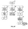
- Fig. 5Gshows the various paths by which second level controller 14 moves from RUN-DOWN-PRIMARIES-TO-SECONDARIES STATE 38 to one of either NONE STATE 28 or SECONDARY STATE 36.
- the first possibilityis that second level controller 14 receives messages 196 from the other second level controller. It then reports back (198) and remains in RUN-DOWN-PRIMARIES-TO-SECONDARIES STATE 38.
- a second possibilityis that the timer, set between BOTH STATE 32 and RUN-DOWN-PRIMARIES-TO-SECONDARIES STATE 38 times out (200). At this point, second level controller 14 realizes that message 176 (Fig. 5F) was not properly sent. A complete failure has occurred.
- the second level controllerreports (202) that it has released both sets of disk drives, and releases both sets (204). Second level controller 14 then enters NONE STATE 28. Finally, a run down path response message 206 is received acknowledging receipt of message 176 (Fig. 5F) sent between BOTH STATE 32 and RUN-DOWN-PRIMARIES-TO-SECONDARIES STATE 38. Second level controller 14 releases its primary drives 208 and enter SECONDARY STATE 36.
- Fig. 5Hshows the possible paths down which second level controller 14 moves between RUN-DOWN-SECONDARIES-TO-PRIMARIES STATE 34 and one of either NONE STATE 28 or PRIMARY STATE 26.
- a first possibilityis that second level controller 14 receives a message 210 from the other second level controller. It then reports back (212) and remains in RUN-DOWN-SECONDARIES-TO-PRIMARIES STATE 34.
- a second possibilityis that the timer, set between BOTH STATE 32 and RUN-DOWN-SECONDARIES-TO PRIMARY-STATE 34 times out (214). If this occurs, second level controller 14 realizes that message 184 (Fig. 5F) was not properly sent. A complete failure has occurred.
- Second level controllerthen sends a message 216 indicating that it has released its drives and then it releases both sets of disk drives (218) which it controls. Second level controller then moves into NONE STATE 28. Finally, a third possibility is that second level controller 14 receives a response 220 to message 184 (Fig. 5F) sent between BOTH STATE 32 and RUN-DOWN-SECONDARIES-TO-PRIMARIES-STATE 34. It will then release (222) its secondary drives and enter PRIMARY STATE 26.
- Fig. 5Ishows the possible paths illustrating the transition of second level controller between RUN-DOWN-BOTH-TO-NONE STATE 42 and NONE STATE 28.
- a message 230may be received from another second level controller providing communication information.
- second level controller 14reports back messages 232 and remains in RUN-DOWN-BOTH-TO-NONE STATE 42.
- the second event which may occuris for the timer, set during transition from BOTH STATE 32 to RUN-DOWN-BOTH-TO-NONE STATE 42, to time out (234). If this happens, second level controller 14 realizes that message 194 (Fig. 5F) sent during BOTH STATE 32 didn't get properly sent and that there has been a complete failure.
- second level controllers and first level controllersmay be implemented in the system.
- the structure of the switching circuitry connecting the second level controllers to the disk drivesmay be altered so that different drives are the primary responsibility of different second level controllers.
Landscapes
- Engineering & Computer Science (AREA)
- Theoretical Computer Science (AREA)
- Quality & Reliability (AREA)
- Physics & Mathematics (AREA)
- General Engineering & Computer Science (AREA)
- General Physics & Mathematics (AREA)
- Signal Processing (AREA)
- Hardware Redundancy (AREA)
- Techniques For Improving Reliability Of Storages (AREA)
Abstract
Description
Claims (8)
- An I/O system for linking a computer (10) to a plurality of memory devices(20) for controlling data flow between a computer and a plurality ofmemory devices arranged in a particular logical configuration wherein afailure of a portion of said I/O system is transparent to the computer whichcontinues to view the plurality of memory devices in the particular logicalconfiguration,comprising:characterised by:a plurality of first-level controllers (12) for handling input/output storagecommunications with the computer;a pair of second-level controllers (14), each connected to each of saidplurality of first-level controllers and the other second-level controller, forproviding a data path from said first-level controllers to each of a primarygroup of said memory devices, and for providing a data path to asecondary group of said memory devices formerly primarily controlled bythe other second-level controller if the other second-level controller fails; andeach second-level controller having a primary control/sense line (50a) forcontrolling said primary group of said memory devices, and an alternatecontrol/sense line (52a) for controlling said secondary group of saidmemory devices;first communication lines connected between said second-level controllerssuch that when one of said second-level controllers fails, said othersecond-level controller determines that a failure has occurred so that saidother second-level controller can assume primary control of a subset of memory devices formerly primarily controlled by said one second-levelcontroller.
- The I/O system of claim 1 wherein said one second level controllerinforms said other second level controller of a failure.
- The I/O system of claim 1 further comprising switching means (16A,16B,16M)connected between said pair of second-level controllers and saidplurality of memory devices for transferring control from a first second-levelcontroller upon failure to a second-level controller.
- The I/O system of claim 1 wherein each second-level controller furthercomprises a second-level controller recovery system for issuing signals toand receiving signals from said first-level controllers and said at least oneother second-level controller.
- The system of claim 1 wherein each second-level controller furthercomprises a state machine capable of maintaining said second-levelcontroller in a number of states, each state representing a systemconfiguration wherein said second-level controller controls particularmemory devices.
- A method for use in an I/O system according to claim 1 for controlling data flow between acomputer (10) and a plurality of memory devices (20), said methodcomprising the steps of:wherein each second-level controller is controlling a primary group of saidmemory devices by means of a primary control/sense line (50a) and asecondary group of memory devices through an alternate control/senseline (52a).arranging said memory devices in a particular logical configuration;providing a plurality of first level controllers and a pair of second-levelcontrollers, with multiple data paths as defined in claim 1 to said memory devices through said first and second levelcontrollers;determining through said first communication lines that a first second-level controller has stopped functioningproperly; andissuing a first switching signal to switch paths from a first first-levelcontroller to a second-level controller path between a first first-level controllerand the first second-level controller to a second controller path between thefirst first-level controller and the second second-level controller, therebytransferring control of a plurality of memory devices from a first second-level controllerto a second second-level controller such that the particular logicalconfiguration of the plurality of memory devices remains constant,
- The method of claim 6 further comprising the steps of issuing a secondswitching signal to switch paths from a third path between a second first-levelcontroller and the first second-level controller to a fourth path betweenthe second first-level controller and the second second-level controller.
- The method of claim 7 further comprising the step of issuing a thirdswitching signal causing control of said plurality of memory devices which are disk drives, undercontrol of the first second-level controller to be switched.
Applications Claiming Priority (3)
| Application Number | Priority Date | Filing Date | Title |
|---|---|---|---|
| US506703 | 1990-04-06 | ||
| US07/506,703US5212785A (en) | 1990-04-06 | 1990-04-06 | Apparatus and method for controlling data flow between a computer and memory devices |
| PCT/US1991/002314WO1991017506A1 (en) | 1990-04-06 | 1991-04-03 | Apparatus and method for controlling data flow between a computer and memory devices |
Publications (3)
| Publication Number | Publication Date |
|---|---|
| EP0524247A1 EP0524247A1 (en) | 1993-01-27 |
| EP0524247A4 EP0524247A4 (en) | 1994-02-16 |
| EP0524247B1true EP0524247B1 (en) | 1999-01-20 |
Family
ID=24015677
Family Applications (1)
| Application Number | Title | Priority Date | Filing Date |
|---|---|---|---|
| EP91907931AExpired - LifetimeEP0524247B1 (en) | 1990-04-06 | 1991-04-03 | Apparatus and method for controlling data flow between a computer and memory devices |
Country Status (5)
| Country | Link |
|---|---|
| US (2) | US5212785A (en) |
| EP (1) | EP0524247B1 (en) |
| AU (1) | AU7688691A (en) |
| DE (1) | DE69130799T2 (en) |
| WO (1) | WO1991017506A1 (en) |
Families Citing this family (43)
| Publication number | Priority date | Publication date | Assignee | Title |
|---|---|---|---|---|
| US5212785A (en)* | 1990-04-06 | 1993-05-18 | Micro Technology, Inc. | Apparatus and method for controlling data flow between a computer and memory devices |
| US5414818A (en)* | 1990-04-06 | 1995-05-09 | Mti Technology Corporation | Method and apparatus for controlling reselection of a bus by overriding a prioritization protocol |
| US5379417A (en)* | 1991-11-25 | 1995-01-03 | Tandem Computers Incorporated | System and method for ensuring write data integrity in a redundant array data storage system |
| WO1993018456A1 (en)* | 1992-03-13 | 1993-09-16 | Emc Corporation | Multiple controller sharing in a redundant storage array |
| US6332675B1 (en) | 1992-07-24 | 2001-12-25 | Canon Kabushiki Kaisha | Ink container, ink and ink jet recording apparatus using ink container |
| JPH06214897A (en)* | 1992-12-14 | 1994-08-05 | E Syst Inc | Method for minimization of loss of data stored in peripheral device in detection of error status |
| US6154850A (en)* | 1993-11-01 | 2000-11-28 | Beaufort River, Inc. | Data storage system and method |
| US5446855A (en)* | 1994-02-07 | 1995-08-29 | Buslogic, Inc. | System and method for disk array data transfer |
| DE69521101T2 (en)* | 1994-10-31 | 2001-10-18 | International Business Machines Corp., Armonk | Shared virtual disks with application-transparent recovery |
| DE69523124T2 (en)* | 1994-12-15 | 2002-05-29 | Hewlett-Packard Co. (N.D.Ges.D.Staates Delaware), Palo Alto | Fault detection system for a mirrored memory in a duplicated controller of a disk storage system |
| US5630054A (en)* | 1995-04-18 | 1997-05-13 | Mti Technology Center | Method and apparatus for storing and retrieving error check information |
| US5696895A (en)* | 1995-05-19 | 1997-12-09 | Compaq Computer Corporation | Fault tolerant multiple network servers |
| FR2737782B1 (en)* | 1995-08-11 | 1997-10-31 | Deroux Dauphin Patrice | TESTABLE ELECTRONIC SYSTEM |
| US6467046B1 (en)* | 1996-05-06 | 2002-10-15 | Sun Microsystems, Inc. | System and method for automatically distributing copies of a replicated database in a computer system |
| US5742753A (en)* | 1996-06-06 | 1998-04-21 | The Boeing Company | Mesh interconnected array in a fault-tolerant computer system |
| US6237047B1 (en)* | 1996-09-30 | 2001-05-22 | Dialogic Corporation | Signal processing system including plurality of processing cards communicating with plurality of independent CPU |
| US5991852A (en)* | 1996-10-28 | 1999-11-23 | Mti Technology Corporation | Cache ram using a secondary controller and switching circuit and improved chassis arrangement |
| US5922077A (en)* | 1996-11-14 | 1999-07-13 | Data General Corporation | Fail-over switching system |
| FR2762695B1 (en)* | 1997-04-29 | 1999-05-28 | Bull Sa | METHOD AND DEVICE FOR CONNECTING THE CENTRAL UNIT OF A DATA PROCESSING SYSTEM TO A REDUNDANT DATA STORAGE SUBSYSTEM |
| US6070251A (en)* | 1997-06-26 | 2000-05-30 | Sun Microsystems, Inc. | Method and apparatus for high availability and caching data storage devices |
| USRE42761E1 (en) | 1997-12-31 | 2011-09-27 | Crossroads Systems, Inc. | Storage router and method for providing virtual local storage |
| US5941972A (en)* | 1997-12-31 | 1999-08-24 | Crossroads Systems, Inc. | Storage router and method for providing virtual local storage |
| US6038626A (en)* | 1998-03-17 | 2000-03-14 | International Business Machines Corporation | Method for controlling data transfers and routing |
| US5996040A (en)* | 1998-03-17 | 1999-11-30 | International Business Machines Corporation | Scalable, modular selector system |
| US6581136B1 (en) | 1999-06-30 | 2003-06-17 | Emc Corporation | Fibre channel data storage system having expansion/contraction |
| US6629216B1 (en) | 1999-06-30 | 2003-09-30 | Emc Corporation | Fibre channel by-pass |
| US6567890B1 (en) | 1999-06-30 | 2003-05-20 | Emc Corporation | Fibre channel port by-pass selector section for dual ported disk drives |
| US6636934B1 (en) | 1999-06-30 | 2003-10-21 | Emc Corporation | Fiber channel port by-pass selector section for dual ported disk drives |
| US6845410B1 (en)* | 1999-09-29 | 2005-01-18 | Silicon Graphics, Inc. | System and method for a hierarchical system management architecture of a highly scalable computing system |
| US6571355B1 (en)* | 1999-12-29 | 2003-05-27 | Emc Corporation | Fibre channel data storage system fail-over mechanism |
| US6574687B1 (en) | 1999-12-29 | 2003-06-03 | Emc Corporation | Fibre channel data storage system |
| US6615315B1 (en) | 1999-12-29 | 2003-09-02 | Emc Corporation | Fibre channel data storage system having improved fro-end I/O adapted hub |
| US6560683B1 (en) | 1999-12-29 | 2003-05-06 | Emc Corporation | Fibre channel data storage system having improved rear-end I/O adapted hub |
| US6389559B1 (en)* | 2000-05-24 | 2002-05-14 | Mti Technology Corporation | Controller fail-over without device bring-up |
| US6820212B2 (en) | 2001-02-20 | 2004-11-16 | Digi-Data Corporation | RAID system having channel capacity unaffected by any single component failure |
| US6715101B2 (en) | 2001-03-15 | 2004-03-30 | Hewlett-Packard Development Company, L.P. | Redundant controller data storage system having an on-line controller removal system and method |
| US6802023B2 (en) | 2001-03-15 | 2004-10-05 | Hewlett-Packard Development Company, L.P. | Redundant controller data storage system having hot insertion system and method |
| US6708285B2 (en) | 2001-03-15 | 2004-03-16 | Hewlett-Packard Development Company, L.P. | Redundant controller data storage system having system and method for handling controller resets |
| US6983397B2 (en)* | 2001-11-29 | 2006-01-03 | International Business Machines Corporation | Method, system, and program for error handling in a dual adaptor system where one adaptor is a master |
| US6957361B2 (en)* | 2001-11-29 | 2005-10-18 | International Business Machines Corporation | Method, system, and program for error handling in a dual adaptor system |
| JP2005301565A (en) | 2004-04-09 | 2005-10-27 | Hitachi Ltd | Disk array device and diagnostic control method for disk array device |
| US20060020720A1 (en)* | 2004-07-23 | 2006-01-26 | Lsi Logic Corporation | Multi-controller IO shipping |
| JP4739432B2 (en)* | 2009-02-25 | 2011-08-03 | 富士通株式会社 | Redundant system, control device, and control method |
Citations (1)
| Publication number | Priority date | Publication date | Assignee | Title |
|---|---|---|---|---|
| WO1991013399A1 (en)* | 1990-03-02 | 1991-09-05 | Sf2 Corporation | Disk array system |
Family Cites Families (53)
| Publication number | Priority date | Publication date | Assignee | Title |
|---|---|---|---|---|
| US3303482A (en)* | 1963-02-25 | 1967-02-07 | Rca Corp | Redundant recording system with parity checking |
| US3377623A (en)* | 1965-09-29 | 1968-04-09 | Foxboro Co | Process backup system |
| GB1233087A (en)* | 1967-07-15 | 1971-05-26 | ||
| US3544777A (en)* | 1967-11-06 | 1970-12-01 | Trw Inc | Two memory self-correcting system |
| DE1963895C3 (en)* | 1969-06-21 | 1973-11-29 | Licentia Patent-Verwaltungs-Gmbh, 6000 Frankfurt | Data memory and data memory control circuit |
| US3803560A (en)* | 1973-01-03 | 1974-04-09 | Honeywell Inf Systems | Technique for detecting memory failures and to provide for automatically for reconfiguration of the memory modules of a memory system |
| US3792448A (en)* | 1973-05-21 | 1974-02-12 | Burroughs Corp | Failsoft peripheral exchange |
| US3905023A (en)* | 1973-08-15 | 1975-09-09 | Burroughs Corp | Large scale multi-level information processing system employing improved failsaft techniques |
| US3964056A (en)* | 1974-04-08 | 1976-06-15 | International Standard Electric Corporation | System for transferring data between central units and controlled units |
| GB1497680A (en)* | 1974-10-29 | 1978-01-12 | Int Computers Ltd | Digital data storage apparatus |
| US3917933A (en)* | 1974-12-17 | 1975-11-04 | Sperry Rand Corp | Error logging in LSI memory storage units using FIFO memory of LSI shift registers |
| US4070704A (en)* | 1976-05-17 | 1978-01-24 | Honeywell Information Systems Inc. | Automatic reconfiguration apparatus for input/output processor |
| US4093985A (en)* | 1976-11-05 | 1978-06-06 | North Electric Company | Memory sparing arrangement |
| US4207609A (en)* | 1978-05-08 | 1980-06-10 | International Business Machines Corporation | Method and means for path independent device reservation and reconnection in a multi-CPU and shared device access system |
| US4205374A (en)* | 1978-10-19 | 1980-05-27 | International Business Machines Corporation | Method and means for CPU recovery of non-logged data from a storage subsystem subject to selective resets |
| CA1102007A (en)* | 1979-05-15 | 1981-05-26 | Prem L. Sood | Duplicated memory system having status indication |
| US4339804A (en)* | 1979-07-05 | 1982-07-13 | Ncr Corporation | Memory system wherein individual bits may be updated |
| US4467421A (en)* | 1979-10-18 | 1984-08-21 | Storage Technology Corporation | Virtual storage system and method |
| JPS5688549A (en)* | 1979-12-21 | 1981-07-18 | Toshiba Corp | Multiplex system for external memory device in electronic computer system |
| JPS5694593A (en)* | 1979-12-27 | 1981-07-31 | Fujitsu Ltd | Storage device |
| JPS56163596A (en)* | 1980-05-16 | 1981-12-16 | Fujitsu Ltd | Memory control system |
| JPS57111890A (en)* | 1980-12-29 | 1982-07-12 | Fujitsu Ltd | Storage device |
| JPS57111893A (en)* | 1980-12-29 | 1982-07-12 | Fujitsu Ltd | Relieving system of defective memory |
| US4423480A (en)* | 1981-03-06 | 1983-12-27 | International Business Machines Corporation | Buffered peripheral system with priority queue and preparation for signal transfer in overlapped operations |
| US4396984A (en)* | 1981-03-06 | 1983-08-02 | International Business Machines Corporation | Peripheral systems employing multipathing, path and access grouping |
| JPS57169297A (en)* | 1981-04-10 | 1982-10-18 | Matsushita Electric Industrial Co Ltd | Device for connecting circuit board |
| JPS57195397A (en)* | 1981-05-28 | 1982-12-01 | Nec Corp | Locally doubled storage device |
| US4507730A (en)* | 1981-10-01 | 1985-03-26 | Honeywell Information Systems Inc. | Memory system with automatic memory configuration |
| US4468731A (en)* | 1981-12-15 | 1984-08-28 | Honeywell Information Systems Inc. | Identification apparatus for use in a controller to facilitate the diagnosis of faults |
| US4464747A (en)* | 1982-02-18 | 1984-08-07 | The Singer Company | High reliability memory |
| US4825403A (en)* | 1983-05-16 | 1989-04-25 | Data General Corporation | Apparatus guaranteeing that a controller in a disk drive system receives at least some data from an invalid track sector |
| JPS60156152A (en)* | 1984-01-25 | 1985-08-16 | Fujitsu Ltd | Memory information protecting system |
| FR2561428B1 (en)* | 1984-03-16 | 1986-09-12 | Bull Sa | DISC MEMORY RECORDING METHOD AND DISC MEMORY SYSTEM |
| JPS6199999A (en)* | 1984-10-19 | 1986-05-19 | Hitachi Ltd | semiconductor storage device |
| US4697232A (en)* | 1984-11-30 | 1987-09-29 | Storage Technology Corporation | I/O device reconnection in a multiple-CPU, dynamic path allocation environment |
| US4667326A (en)* | 1984-12-20 | 1987-05-19 | Advanced Micro Devices, Inc. | Method and apparatus for error detection and correction in systems comprising floppy and/or hard disk drives |
| US4814982A (en)* | 1984-12-24 | 1989-03-21 | General Electric Company | Reconfigurable, multiprocessor system with protected, multiple, memories |
| JPS61264599A (en)* | 1985-05-16 | 1986-11-22 | Fujitsu Ltd | semiconductor storage device |
| US4722085A (en)* | 1986-02-03 | 1988-01-26 | Unisys Corp. | High capacity disk storage system having unusually high fault tolerance level and bandpass |
| US4761785B1 (en)* | 1986-06-12 | 1996-03-12 | Ibm | Parity spreading to enhance storage access |
| JPH0719426B2 (en)* | 1986-11-07 | 1995-03-06 | 日本電気株式会社 | Disk controller |
| US4868818A (en)* | 1987-10-29 | 1989-09-19 | The United States Of America As Represented By The Administrator Of The National Aeronautics And Space Administration | Fault tolerant hypercube computer system architecture |
| US4899342A (en)* | 1988-02-01 | 1990-02-06 | Thinking Machines Corporation | Method and apparatus for operating multi-unit array of memories |
| US4993030A (en)* | 1988-04-22 | 1991-02-12 | Amdahl Corporation | File system for a plurality of storage classes |
| US4914656A (en)* | 1988-06-28 | 1990-04-03 | Storage Technology Corporation | Disk drive memory |
| US5053942A (en)* | 1988-11-01 | 1991-10-01 | The Regents Of The University Of California | Bit-sliced cross-connect chip having a tree topology of arbitration cells for connecting memory modules to processors in a multiprocessor system |
| AU630635B2 (en)* | 1988-11-14 | 1992-11-05 | Emc Corporation | Arrayed disk drive system and method |
| US5091847A (en)* | 1989-10-03 | 1992-02-25 | Grumman Aerospace Corporation | Fault tolerant interface station |
| US5212785A (en)* | 1990-04-06 | 1993-05-18 | Micro Technology, Inc. | Apparatus and method for controlling data flow between a computer and memory devices |
| US5195100A (en)* | 1990-03-02 | 1993-03-16 | Micro Technology, Inc. | Non-volatile memory storage of write operation identifier in data sotrage device |
| US5166939A (en)* | 1990-03-02 | 1992-11-24 | Micro Technology, Inc. | Data storage apparatus and method |
| US5134619A (en)* | 1990-04-06 | 1992-07-28 | Sf2 Corporation | Failure-tolerant mass storage system |
| US5233618A (en)* | 1990-03-02 | 1993-08-03 | Micro Technology, Inc. | Data correcting applicable to redundant arrays of independent disks |
- 1990
- 1990-04-06USUS07/506,703patent/US5212785A/ennot_activeExpired - Lifetime
- 1991
- 1991-04-03EPEP91907931Apatent/EP0524247B1/ennot_activeExpired - Lifetime
- 1991-04-03AUAU76886/91Apatent/AU7688691A/ennot_activeAbandoned
- 1991-04-03DEDE69130799Tpatent/DE69130799T2/ennot_activeExpired - Fee Related
- 1991-04-03WOPCT/US1991/002314patent/WO1991017506A1/enactiveIP Right Grant
- 1995
- 1995-04-12USUS08/422,005patent/US5651110A/ennot_activeExpired - Lifetime
Patent Citations (1)
| Publication number | Priority date | Publication date | Assignee | Title |
|---|---|---|---|---|
| WO1991013399A1 (en)* | 1990-03-02 | 1991-09-05 | Sf2 Corporation | Disk array system |
Also Published As
| Publication number | Publication date |
|---|---|
| EP0524247A4 (en) | 1994-02-16 |
| AU7688691A (en) | 1991-11-27 |
| EP0524247A1 (en) | 1993-01-27 |
| WO1991017506A1 (en) | 1991-11-14 |
| US5651110A (en) | 1997-07-22 |
| DE69130799T2 (en) | 1999-05-27 |
| DE69130799D1 (en) | 1999-03-04 |
| US5212785A (en) | 1993-05-18 |
Similar Documents
| Publication | Publication Date | Title |
|---|---|---|
| EP0524247B1 (en) | Apparatus and method for controlling data flow between a computer and memory devices | |
| US5636341A (en) | Fault processing method and information processing system | |
| US6154850A (en) | Data storage system and method | |
| US4014005A (en) | Configuration and control unit for a heterogeneous multi-system | |
| EP0449964B1 (en) | Distributed switching architecture for communication module redundancy | |
| EP0517857B1 (en) | Disk array system and method | |
| EP0399308A2 (en) | Computer network for real time control with automatic fault identification and by-pass | |
| US6038681A (en) | Multi-array disk apparatus | |
| JPS6321929B2 (en) | ||
| JPS63268038A (en) | Controller | |
| JPS60102089A (en) | Method of operating multiprocessor control computer | |
| JPH01145701A (en) | Data link system for programmable controller | |
| JPS6217258B2 (en) | ||
| JPH0484230A (en) | Activation maintenance system for supervisory device | |
| KR19980067077A (en) | Redundant Control System and Its Control Method | |
| JPS58127263A (en) | Switching device | |
| SU1702434A1 (en) | Majority redundant memory interface | |
| JP2529250B2 (en) | Duplex system switching system | |
| KR930003153B1 (en) | Auxiliary memory duel system | |
| JP2563632B2 (en) | Double transmission bus type transmission system | |
| JPH0563713A (en) | Transmission line duplex bus type transmission system | |
| JP3843388B2 (en) | Process control device | |
| JPWO2002063890A1 (en) | Cross connect device | |
| JPH01266633A (en) | Redundant control system | |
| JPH06197121A (en) | System switching system for redundant constitution of atm switchboard |
Legal Events
| Date | Code | Title | Description |
|---|---|---|---|
| PUAI | Public reference made under article 153(3) epc to a published international application that has entered the european phase | Free format text:ORIGINAL CODE: 0009012 | |
| 17P | Request for examination filed | Effective date:19921104 | |
| AK | Designated contracting states | Kind code of ref document:A1 Designated state(s):DE FR GB IT | |
| RAP1 | Party data changed (applicant data changed or rights of an application transferred) | Owner name:MICRO TECHNOLOGY, INC. | |
| A4 | Supplementary search report drawn up and despatched | Effective date:19931229 | |
| AK | Designated contracting states | Kind code of ref document:A4 Designated state(s):DE FR GB IT | |
| 17Q | First examination report despatched | Effective date:19960711 | |
| GRAG | Despatch of communication of intention to grant | Free format text:ORIGINAL CODE: EPIDOS AGRA | |
| RAP1 | Party data changed (applicant data changed or rights of an application transferred) | Owner name:EMC CORPORATION | |
| GRAG | Despatch of communication of intention to grant | Free format text:ORIGINAL CODE: EPIDOS AGRA | |
| GRAH | Despatch of communication of intention to grant a patent | Free format text:ORIGINAL CODE: EPIDOS IGRA | |
| GRAH | Despatch of communication of intention to grant a patent | Free format text:ORIGINAL CODE: EPIDOS IGRA | |
| GRAA | (expected) grant | Free format text:ORIGINAL CODE: 0009210 | |
| AK | Designated contracting states | Kind code of ref document:B1 Designated state(s):DE FR GB IT | |
| ITF | It: translation for a ep patent filed | ||
| REF | Corresponds to: | Ref document number:69130799 Country of ref document:DE Date of ref document:19990304 | |
| PG25 | Lapsed in a contracting state [announced via postgrant information from national office to epo] | Ref country code:DE Free format text:LAPSE BECAUSE OF FAILURE TO SUBMIT A TRANSLATION OF THE DESCRIPTION OR TO PAY THE FEE WITHIN THE PRESCRIBED TIME-LIMIT Effective date:19990421 | |
| ET | Fr: translation filed | ||
| PLBE | No opposition filed within time limit | Free format text:ORIGINAL CODE: 0009261 | |
| STAA | Information on the status of an ep patent application or granted ep patent | Free format text:STATUS: NO OPPOSITION FILED WITHIN TIME LIMIT | |
| 26N | No opposition filed | ||
| REG | Reference to a national code | Ref country code:GB Ref legal event code:IF02 | |
| PGFP | Annual fee paid to national office [announced via postgrant information from national office to epo] | Ref country code:DE Payment date:20070531 Year of fee payment:17 | |
| PGFP | Annual fee paid to national office [announced via postgrant information from national office to epo] | Ref country code:GB Payment date:20070425 Year of fee payment:17 | |
| PGFP | Annual fee paid to national office [announced via postgrant information from national office to epo] | Ref country code:IT Payment date:20070523 Year of fee payment:17 | |
| PGFP | Annual fee paid to national office [announced via postgrant information from national office to epo] | Ref country code:FR Payment date:20070417 Year of fee payment:17 | |
| GBPC | Gb: european patent ceased through non-payment of renewal fee | Effective date:20080403 | |
| PG25 | Lapsed in a contracting state [announced via postgrant information from national office to epo] | Ref country code:DE Free format text:LAPSE BECAUSE OF NON-PAYMENT OF DUE FEES Effective date:20081101 | |
| REG | Reference to a national code | Ref country code:FR Ref legal event code:ST Effective date:20081231 | |
| PG25 | Lapsed in a contracting state [announced via postgrant information from national office to epo] | Ref country code:FR Free format text:LAPSE BECAUSE OF NON-PAYMENT OF DUE FEES Effective date:20080430 | |
| PG25 | Lapsed in a contracting state [announced via postgrant information from national office to epo] | Ref country code:GB Free format text:LAPSE BECAUSE OF NON-PAYMENT OF DUE FEES Effective date:20080403 | |
| PG25 | Lapsed in a contracting state [announced via postgrant information from national office to epo] | Ref country code:IT Free format text:LAPSE BECAUSE OF NON-PAYMENT OF DUE FEES Effective date:20080403 |