EP0523988A1 - Image projector - Google Patents
Image projectorDownload PDFInfo
- Publication number
- EP0523988A1 EP0523988A1EP92306499AEP92306499AEP0523988A1EP 0523988 A1EP0523988 A1EP 0523988A1EP 92306499 AEP92306499 AEP 92306499AEP 92306499 AEP92306499 AEP 92306499AEP 0523988 A1EP0523988 A1EP 0523988A1
- Authority
- EP
- European Patent Office
- Prior art keywords
- lens group
- image
- color
- tri
- lens
- Prior art date
- Legal status (The legal status is an assumption and is not a legal conclusion. Google has not performed a legal analysis and makes no representation as to the accuracy of the status listed.)
- Granted
Links
- 230000003287optical effectEffects0.000claimsabstractdescription42
- 239000002131composite materialSubstances0.000claimsabstractdescription30
- 239000000203mixtureSubstances0.000claimsabstractdescription18
- 238000000926separation methodMethods0.000claimsabstractdescription17
- 230000014509gene expressionEffects0.000description6
- 230000010287polarizationEffects0.000description5
- 238000010276constructionMethods0.000description4
- 239000004973liquid crystal related substanceSubstances0.000description4
- 238000000034methodMethods0.000description4
- 230000004075alterationEffects0.000description3
- 230000000903blocking effectEffects0.000description3
- 239000011521glassSubstances0.000description2
- 239000000758substrateSubstances0.000description2
- 239000000470constituentSubstances0.000description1
- 230000003247decreasing effectEffects0.000description1
- 238000012986modificationMethods0.000description1
- 230000004048modificationEffects0.000description1
- 210000001747pupilAnatomy0.000description1
- 238000004904shorteningMethods0.000description1
Images

Classifications
- H—ELECTRICITY
- H04—ELECTRIC COMMUNICATION TECHNIQUE
- H04N—PICTORIAL COMMUNICATION, e.g. TELEVISION
- H04N9/00—Details of colour television systems
- H04N9/12—Picture reproducers
- H04N9/31—Projection devices for colour picture display, e.g. using electronic spatial light modulators [ESLM]
- H04N9/3102—Projection devices for colour picture display, e.g. using electronic spatial light modulators [ESLM] using two-dimensional electronic spatial light modulators
- H04N9/3105—Projection devices for colour picture display, e.g. using electronic spatial light modulators [ESLM] using two-dimensional electronic spatial light modulators for displaying all colours simultaneously, e.g. by using two or more electronic spatial light modulators
- H—ELECTRICITY
- H04—ELECTRIC COMMUNICATION TECHNIQUE
- H04N—PICTORIAL COMMUNICATION, e.g. TELEVISION
- H04N5/00—Details of television systems
- H04N5/74—Projection arrangements for image reproduction, e.g. using eidophor
- H04N5/7416—Projection arrangements for image reproduction, e.g. using eidophor involving the use of a spatial light modulator, e.g. a light valve, controlled by a video signal
- H04N5/7441—Projection arrangements for image reproduction, e.g. using eidophor involving the use of a spatial light modulator, e.g. a light valve, controlled by a video signal the modulator being an array of liquid crystal cells
- H—ELECTRICITY
- H04—ELECTRIC COMMUNICATION TECHNIQUE
- H04N—PICTORIAL COMMUNICATION, e.g. TELEVISION
- H04N7/00—Television systems
- H04N7/01—Conversion of standards, e.g. involving analogue television standards or digital television standards processed at pixel level
- H04N7/0117—Conversion of standards, e.g. involving analogue television standards or digital television standards processed at pixel level involving conversion of the spatial resolution of the incoming video signal
- H04N7/0122—Conversion of standards, e.g. involving analogue television standards or digital television standards processed at pixel level involving conversion of the spatial resolution of the incoming video signal the input and the output signals having different aspect ratios
Definitions
- the present inventionrelates to improvements of an image projector and more particularly to an image projector capable of displaying a high definition image in spite of a short projection length.
- the image projectorhas such a construction as capable of projecting a composite image consist of the three color images from three liquid crystal panels on a screen through a polarization beam splitter and a tri-color separation and composition optical system having dichroic filters.
- Fig. 1is a explanatory view for explaining formulas of lens in the prior art, wherein the numeral 30 indicates a focusing lens, 31 an object, and 32 an image.
- the symbol 'f'indicates focal length of the lens 30, 'F a ' object focal point, 'F b ' image focal point, 'a' a distance of the object 31 from the center of the lens 30, 'b' a distance of the image 32 from the center of the lens 30, 'b.f.' a back-focal length defined as a distance between the front surface of the lens 30 and object focal point F a or a distance between the rear surface of the lens 30 and the image focal point F b , 'h a ' a height of the object 31, 'h b ' a height of the image 32.
- the expressions (3) and (4)are derived from the expression (1) and (2), wherein 'm' indicates the magnification of the lens 30.
- the aforementioned image projectorrequires a projection lens having a long focal length 'f' because there are installed the polarization beam splitter 24 and a tri-color separation and composition optical system 25 between a group of liquid crystal panels 21, 22, and 23 and the projection lens 16, as described hereafter referring to Fig. 3 and Fig. 4, which poses a great difficulty to obtain a large magnified projection image on the screen at a shorter projection distance .
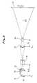
- Fig. 2is an explanatory view for explaining the Retro-Focus method in the prior art.
- an optical lens systemconsists of a concave lens group 1 and convex lens group 2 having an overall focal length 'f'. After a light 3 coming in parallel with an optical axis 4 is incident to the concave lens group 1 and refracted outward away from the optical axis 4, the light 3 is incident to the convex lens group 2 and refracted inward toward the optical axis 4, so that it can be obtained a back focal length 'b.f.' which is longer than the focal length f.
- a general object of the present inventionis to provide a novel and useful image projector in which the above disadvantage has been eliminated.
- a more specific object of the present inventionis to provide an image projector for projecting a magnified tri-color composite optical image on a screen.
- the image projectorgenerally comprises a light source emitting a reading light, image forming means provided correspondingly with Red, Green and Blue color images, a tri-color separation and composition optical system for obtaining the the tri-color composite beam from the image forming device, and a lens system comprising of a first lens group, a second lens group and a third lens group disposed along a optic axis in order.
- a focal length of the overall lens systemis made shorter than a back-focal length defined as a distance between the front surface of the first lens group and an object focal point of the overall lens system.
- the reading light beam emitted from a light sourceis separated into three color beams, e. g, Red, Green and Blue color beams through a tri-color separation and composition optical system.
- the separated color beamsirradiate on image forming devices provided correspondingly with Red, Green and Blue color images to read out color images therefrom, respectively.
- the first lens groupforms a composite light image on the second lens group by focusing the composite image beam from the tri-color separation and composition optical system.
- the second lens groupconverges the composite image beam therefrom to the third lens group.
- the third lens groupprojects the the composite image beam on the screen as a magnified image picture.
- Fig. 1is an explanatory view for explaining formulas of lens in the prior art.
- Fig. 2is an explanatory view for explaining the Retro-Focus method in the prior art.
- Fig. 3is an explanatory view showing a basic structure of an image projector according to the present invention.
- Fig. 4is an explanatory view of an embodiment of the present invention.
- Fig. 5is an explanatory view of a structure of a spatial light modulator.
- Fig. 3is an explanatory view showing a basic structure of an image projector according to the present invention, in which the numeral 10 indicates a Red image forming device, 11 a Green image forming device, 12 a Blue image forming device, 13 a tri-color separation and composition optical system, 14 a first lens group having a back-focal length 'b.f.' defined as a distance between a front surface of the first lens group and an object focal point 'F1', 15 a second lens group for converging an incident light, 16 a third lens group having an object focal point 'F3' and a focal length 'f3' for projecting a magnified image on a screen 17.
- the numeral 10indicates a Red image forming device, 11 a Green image forming device, 12 a Blue image forming device, 13 a tri-color separation and composition optical system, 14 a first lens group having a back-focal length 'b.f.' defined as a distance between a front surface of the first lens group
- Each of the lens groups 14, 15, and 16, the tri-color separation and composition system 13 and the Green image forming device 11are provided along an optical axis OX.
- the Green image forming device 11is positioned in the left side of the object focal point F1 of the first lens group 14 along the optical axis OX.
- the second lens group 15is positioned nearby the object focal point F3 of the third lens group 16.
- Each of the image forming devicesforms a color image in accordance with an intended color, respectively.
- each of the three color lightsrespectively irradiates one of the image forming devices in accordance with the color.
- Each of the lights reflected from the image forming devicesis incident to the tri-color separation and composition system 13 to compose a composite optical image beam, and the composite image beam is focused as a optical image on the second lens group 15 through the first lens group 14.
- the optical image on the second lens group 15is projected on the screen 17 as a predetermined magnified picture through the third lens group 16.
- the focal length 'f' of the overall lens systemcomprising of the lens groups 14, 15, and 16 becomes the same as the focal length 'f3' of the third lens group 16.
- the focal length 'f' of the overall lens systembecomes half of the focal length 'f3' of the third lens system 16.
- the value of the focal length 'f'can be reduced to any value by choosing the value of the focal length 'f3' of the third lens group 16 or by choosing the value of the imagery magnification 'ml' of the first lens group 14. Therefore, according to the present invention, the focal length 'f' of the overall lens system can be easily made shorter than the back-focal length 'b.f' which is defined as a distance between the object focal point 'F1' and the front surface of the first lens group 14.
- the value of the focal length 'f' of the overall lens systemfor instance, below 30 mm.
- thisenables a short focal length of the lens system and realizing a magnified projection image on the screen 17 at a short projection distance between the third lens group 16 and the screen 17.
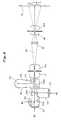
- Fig. 4is an explanatory view of an embodiment of the present invention, in which spatial light modulators are used as the aforementioned image forming devices.
- Fig. 5is an explanatory view of a structure of a spatial light modulator.
- Numerals 20, 21, and 22designate spatial light modulators (image forming means ) correspondingly with Red, Green, and Blue, and to which a description will be given at first, referring to Fig. 5.
- the spatial light modulator 20(21, 22) is formed as such that a glass substrate 20a, a transparent electrode E1, a photoconductive layer 20b, a light blocking layer 20c, a dielectric mirror 20d, a photomodulation layer 20e, an another transparent electrode E1, and another glass substrate 20 f are laminated in order.
- a power source Eis connected between the transparent electrodes E1, E2, and a writing light WL carrying desired information impinges on the photoconductive layer 20b through the transparent electrode E1, so that electric resistance of the photoconductive layer 20b is changed correspondingly with the intensity distribution of the beam of writing light WL, thus, an electric charge image is formed at an interface between the photoconductive layer 20b and the light blocking layer 20 correspondingly with the intensity distribution of the writing light WL.
- the reading light RLUpon reading the image of electric charge, the reading light RL impinges on the photomodulation layer 20e through the transparent electrode E2.
- the reading light having passed the photomodulation layer 20eis reflected by the dielectric mirror 20d, and is projected outward through the photomodulation layer 20e and the transparent electrode E2.
- the reflected reading light RLis modulated by the photomodulation layer 20e correspondingly with the intensity distribution of the charge image formed on the interface between the photoconductive layer 20b and the light blocking layer 20c, and is projected as a beam light corresponding to the field intensity distribution.
- numeral 20, 21 and 22indicate spatial light modulators for color image forming means, e.g., Red color, Green color and Blue color, respectively, 23 a light source for a reading light RL, 24 a polarization beam splitter with a semi-transparent mirror film 24a set at 45 degree angle toward an optical axis OX therein, 25 a tri-color separation and composition optical system comprising a dichroic filter 25a and 25b, 14a an iris of the first lens group for controlling the light quantity, 16a an iris of the third lens group 16.
- the reading light beam RL emitted from a light source 23is irradiated on the semi-transparent mirror film 24a of the polarization beam splitter 24, and is reflected by the semi-transparent mirror film 24a at right angles toward left.
- the reflected light beamis an S-polarized light beam, and impinges on the tri-color separation and composition optical system 25.
- the Green light beam component(referred to as "beam G" ) impinges on the spatial light modulator 21 passing through dichroic filters 25a and 25b.
- the Red light beam component ( beam R ) of the reading light having passed through the dichroic filter 25ais reflected by the dichroic filter 25b at right angles upwardly, and impinges on the spatial light modulator 20.
- the Blue light beam component ( beam B )of the reading lightis reflected by the dichroic filter 25a at right angles downwardly, and impinges on the spatial light modulator 22.
- Each of beams R, G and Bis modulated by and reflected back from the respective spatial light modulators 20, 21, and 22.
- the reflected beams R, G and Bcontain ( intensity modulated )the information corresponding to the respective color images, and impinge again on the tri-color separation and composition optical system 25 through each of the dichroic filters 25a and 25b to compose a single beam of tri-color composite light ( referred to as "composite beam" ).
- composite beamimpinges on the beam splitter 24, where a P polarized light of the composite beam only passes through the beam splitter 24.
- the focal length of the overall lens systemcan be reduced in the foregoing lens construction, so that a magnified projection image is obtain in spite of a short projection length between the third lens group 16 and the screen 17.
- the present inventionenables to obtain a high definition image without decreasing brightness because the beam forming the image is converged on the entrance pupil of the iris 16a of the third lens group 16 by the second lens group 15.
- various kinds of aberrationcan be easily reduced upon realizing a high luminance and high definition image because performance of each of the lens groups can be pursued individually.
- a single component projection lenscan be used in the case of applying the present invention to a Rear-projection display system, so that there exists no relation between the aberration distortion and the shortening of focal length, which realizes a suitable Rear-projection display system.
- the light modulators 20, 21 and 22are employed as image forming devices in the embodiment of the present invention, but it is possible to employ such devices as liquid crystal panels which can modulate the light.
Landscapes
- Engineering & Computer Science (AREA)
- Multimedia (AREA)
- Signal Processing (AREA)
- Chemical & Material Sciences (AREA)
- Crystallography & Structural Chemistry (AREA)
- Projection Apparatus (AREA)
- Liquid Crystal (AREA)
- Lenses (AREA)
- Video Image Reproduction Devices For Color Tv Systems (AREA)
Abstract
Description
- The present invention relates to improvements of an image projector and more particularly to an image projector capable of displaying a high definition image in spite of a short projection length.
- Recently, an image projector has been proposed in which three liquid crystal panels are employed correspondingly with Red (R), Green (G) and Blue (B) signals to obtain a high definition image. Therefore, the image projector has such a construction as capable of projecting a composite image consist of the three color images from three liquid crystal panels on a screen through a polarization beam splitter and a tri-color separation and composition optical system having dichroic filters.
- It is well known that, in order to obtain a highly magnified image on the screen at a short projection length defined between the projection lens and the screen, it requires a projection lens having a short focal length. In addition, the projection lens has to be positioned in such a manner that the object focal point of the projection lens resides in the proximity of an object to be projected on the screen. These facts are derived from formulas of lens.
- Fig. 1 is a explanatory view for explaining formulas of lens in the prior art, wherein the
numeral 30 indicates a focusing lens, 31 an object, and 32 an image. The symbol 'f' indicates focal length of thelens 30, 'Fa' object focal point, 'Fb' image focal point, 'a' a distance of theobject 31 from the center of thelens 30, 'b' a distance of theimage 32 from the center of thelens 30, 'b.f.' a back-focal length defined as a distance between the front surface of thelens 30 and object focal point Fa or a distance between the rear surface of thelens 30 and the image focal point Fb, 'ha' a height of theobject 31, 'hb' a height of theimage 32. - The formulas of lens are expressed as follows:


- The expressions (3) and (4) are derived from the expression (1) and (2), wherein 'm' indicates the magnification of the
lens 30. - As clearly understood from the expression (3) and (4), it is effective to use a short focal length 'f' for the short projection length 'b' and is effective to position the
object 31 in the proximity of the object focal point 'Fa' for obtaining a large magnification 'm'. - On the contrary, the aforementioned image projector requires a projection lens having a long focal length 'f' because there are installed the
polarization beam splitter 24 and a tri-color separation and compositionoptical system 25 between a group ofliquid crystal panels projection lens 16, as described hereafter referring to Fig. 3 and Fig. 4, which poses a great difficulty to obtain a large magnified projection image on the screen at a shorter projection distance . - One of the attempts to solve the problem is to provide an optical lens system having a longer back-focal length than a focal length, for instance, called the "Retro-Focus" method.
- Fig. 2 is an explanatory view for explaining the Retro-Focus method in the prior art.
- Referring to Fig. 2, an optical lens system according to the Retro-Focus method consists of a concave lens group 1 and
convex lens group 2 having an overall focal length 'f'. After alight 3 coming in parallel with anoptical axis 4 is incident to the concave lens group 1 and refracted outward away from theoptical axis 4, thelight 3 is incident to theconvex lens group 2 and refracted inward toward theoptical axis 4, so that it can be obtained a back focal length 'b.f.' which is longer than the focal length f. - But, in this case of employing the above optical lens system, there exists such a problem that it is difficult to make use of the optical lens system because of inevitable aberration of various kinds. This results in the failure of obtaining a better high definition image, while a large magnified projection image may be obtained at a short projection distance.
- Accordingly, a general object of the present invention is to provide a novel and useful image projector in which the above disadvantage has been eliminated.
- A more specific object of the present invention is to provide an image projector for projecting a magnified tri-color composite optical image on a screen. The image projector generally comprises a light source emitting a reading light, image forming means provided correspondingly with Red, Green and Blue color images, a tri-color separation and composition optical system for obtaining the the tri-color composite beam from the image forming device, and a lens system comprising of a first lens group, a second lens group and a third lens group disposed along a optic axis in order. A focal length of the overall lens system is made shorter than a back-focal length defined as a distance between the front surface of the first lens group and an object focal point of the overall lens system.
- Upon operation of the image projector of the present invention, the reading light beam emitted from a light source is separated into three color beams, e. g, Red, Green and Blue color beams through a tri-color separation and composition optical system. The separated color beams irradiate on image forming devices provided correspondingly with Red, Green and Blue color images to read out color images therefrom, respectively. Each of reflected light beams from the image forming devices carrying image information, again impinges on the tri-color composition optical system to obtain a composite image beam. The first lens group forms a composite light image on the second lens group by focusing the composite image beam from the tri-color separation and composition optical system. The second lens group converges the composite image beam therefrom to the third lens group. The third lens group projects the the composite image beam on the screen as a magnified image picture.
- Other objects and further features of the present invention will be apparent from the following detailed description when read in conjunction with the accompanying drawing.
- Preferred embodiments of the present invention will be described with reference to the accompanying drawings wherein:
- Fig. 1 is an explanatory view for explaining formulas of lens in the prior art.
- Fig. 2 is an explanatory view for explaining the Retro-Focus method in the prior art.
- Fig. 3 is an explanatory view showing a basic structure of an image projector according to the present invention.
- Fig. 4 is an explanatory view of an embodiment of the present invention.
- Fig. 5 is an explanatory view of a structure of a spatial light modulator.
- Fig. 3 is an explanatory view showing a basic structure of an image projector according to the present invention, in which the
numeral 10 indicates a Red image forming device, 11 a Green image forming device, 12 a Blue image forming device, 13 a tri-color separation and composition optical system, 14 a first lens group having a back-focal length 'b.f.' defined as a distance between a front surface of the first lens group and an object focal point 'F₁', 15 a second lens group for converging an incident light, 16 a third lens group having an object focal point 'F₃' and a focal length 'f₃' for projecting a magnified image on ascreen 17. Each of thelens groups composition system 13 and the Greenimage forming device 11 are provided along an optical axis OX. The Greenimage forming device 11 is positioned in the left side of the object focal point F1 of thefirst lens group 14 along the optical axis OX. Thesecond lens group 15 is positioned nearby the object focal point F₃ of thethird lens group 16. Each of the image forming devices forms a color image in accordance with an intended color, respectively. - Next, a description will be given to the operation of the basic structure of the image projector referring to Fig.3.
- After a reading light from a light source (not shown) is separated into three color lights, R, G and B, through a reflecting mirror, dichroic mirror and so on (described hereafter ), each of the three color lights respectively irradiates one of the image forming devices in accordance with the color. Each of the lights reflected from the image forming devices is incident to the tri-color separation and
composition system 13 to compose a composite optical image beam, and the composite image beam is focused as a optical image on thesecond lens group 15 through thefirst lens group 14. The optical image on thesecond lens group 15 is projected on thescreen 17 as a predetermined magnified picture through thethird lens group 16. - In the above construction, if the composite optical image beam is focused on the
second lens group 15 through thefirst lens group 14 as an optical image with magnification ×1, the focal length 'f' of the overall lens system comprising of thelens groups third lens group 16. - Further, if the composite optical image beam is focused on the
second lens group 15 through thefirst lens group 14 as an optical image with a magnification of ×2, the focal length 'f' of the overall lens system becomes half of the focal length 'f₃' of thethird lens system 16. - These facts can be expressed by means of the following expression:

wherein
ml; the imagery magnification by thefirst lens group 14.
f₃; the focal length of thethird lens group 16.
f ; the focal length of the overall lens system. - The above expression (1) can be easily derived on the basis of a geometrical construction and the basic formulas of lens, however, the detailed discussion is omitted for simplicity here.
- As clearly understood from the expression (5), the value of the focal length 'f' can be reduced to any value by choosing the value of the focal length 'f₃' of the
third lens group 16 or by choosing the value of the imagery magnification 'ml' of thefirst lens group 14. Therefore, according to the present invention, the focal length 'f' of the overall lens system can be easily made shorter than the back-focal length 'b.f' which is defined as a distance between the object focal point 'F₁' and the front surface of thefirst lens group 14. - In this case, it is possible to make the value of the focal length 'f' of the overall lens system, for instance, below 30 mm. Thus, this enables a short focal length of the lens system and realizing a magnified projection image on the
screen 17 at a short projection distance between thethird lens group 16 and thescreen 17. - Fig. 4 is an explanatory view of an embodiment of the present invention, in which spatial light modulators are used as the aforementioned image forming devices.
- Fig. 5 is an explanatory view of a structure of a spatial light modulator.
- In these figures, identical symbols are assigned to the constituents similar or corresponding to those shown in Fig. 3.
Numerals - For instance, the spatial light modulator 20 (21, 22) is formed as such that a glass substrate 20a, a transparent electrode E1, a
photoconductive layer 20b, alight blocking layer 20c, a dielectric mirror 20d, a photomodulation layer 20e, an another transparent electrode E1, and anotherglass substrate 20 f are laminated in order. - Upon writing a light image on the spatial
light modulator 20, a power source E is connected between the transparent electrodes E1, E2, and a writing light WL carrying desired information impinges on thephotoconductive layer 20b through the transparent electrode E1, so that electric resistance of thephotoconductive layer 20b is changed correspondingly with the intensity distribution of the beam of writing light WL, thus, an electric charge image is formed at an interface between thephotoconductive layer 20b and thelight blocking layer 20 correspondingly with the intensity distribution of the writing light WL. - Upon reading the image of electric charge, the reading light RL impinges on the photomodulation layer 20e through the transparent electrode E2. The reading light having passed the photomodulation layer 20e is reflected by the dielectric mirror 20d, and is projected outward through the photomodulation layer 20e and the transparent electrode E2. The reflected reading light RL is modulated by the photomodulation layer 20e correspondingly with the intensity distribution of the charge image formed on the interface between the
photoconductive layer 20b and thelight blocking layer 20c, and is projected as a beam light corresponding to the field intensity distribution. - Next, a description is given to an embodiment of the present invention, referring to Fig. 4.
- In Fig. 4, numeral 20, 21 and 22 indicate spatial light modulators for color image forming means, e.g., Red color, Green color and Blue color, respectively, 23 a light source for a reading light RL, 24 a polarization beam splitter with a
semi-transparent mirror film 24a set at 45 degree angle toward an optical axis OX therein, 25 a tri-color separation and composition optical system comprising adichroic filter third lens group 16. - Next, description is given to the operation of the embodiment of the present invention referring to Fig. 4.
- In Fig. 4, the reading light beam RL emitted from a
light source 23 is irradiated on thesemi-transparent mirror film 24a of thepolarization beam splitter 24, and is reflected by thesemi-transparent mirror film 24a at right angles toward left. The reflected light beam is an S-polarized light beam, and impinges on the tri-color separation and compositionoptical system 25. Thereafter the Green light beam component ( referred to as "beam G" ) impinges on the spatiallight modulator 21 passing throughdichroic filters 25a and 25b. The Red light beam component ( beam R ) of the reading light having passed through the dichroic filter 25a is reflected by thedichroic filter 25b at right angles upwardly, and impinges on the spatiallight modulator 20. Further, the Blue light beam component ( beam B )of the reading light is reflected by the dichroic filter 25a at right angles downwardly, and impinges on the spatiallight modulator 22. Each of beams R, G and B is modulated by and reflected back from the respective spatiallight modulators optical system 25 through each of thedichroic filters 25a and 25b to compose a single beam of tri-color composite light ( referred to as "composite beam" ). The composite beam impinges on thebeam splitter 24, where a P polarized light of the composite beam only passes through thebeam splitter 24. The composite beam having passed through impinges on thefirst lens group 14 and forms an optical image in thesecond lens group 15 by being controlled a quantity of light with theiris 14a. Further, the optical image formed thereon is projected on thescreen 17 as a magnified optical image through thethird lens group 16 by being controlled a quantity of light with the iris 16a. - According to the present invention, although the back focal length 'b.f' becomes longer because the tri-color separation and composition
optical system 25 and thepolarization beam splitter 24 is installed between the group of spatial light modulators ( 20, 21 and 22 ) and thefirst lens group 14, the focal length of the overall lens system can be reduced in the foregoing lens construction, so that a magnified projection image is obtain in spite of a short projection length between thethird lens group 16 and thescreen 17. - Further, the present invention enables to obtain a high definition image without decreasing brightness because the beam forming the image is converged on the entrance pupil of the iris 16a of the
third lens group 16 by thesecond lens group 15. - Further more, according to the present invention, various kinds of aberration can be easily reduced upon realizing a high luminance and high definition image because performance of each of the lens groups can be pursued individually.
- It should be noted that a single component projection lens can be used in the case of applying the present invention to a Rear-projection display system, so that there exists no relation between the aberration distortion and the shortening of focal length, which realizes a suitable Rear-projection display system.
- It should be also noted that, as described in the foregoing, the
light modulators - Although the invention is described in the specific terms, it is to be noted that the described embodiment is not exclusive and various changes and modifications may be imparted without departing from the scope of the invention which is limited solely by the appended claims.


Claims (3)
- An image projector for projecting a tri-color composite light image on a screen comprising:
a light source emitting a reading light;
image forming means provided correspondingly with Red, Green and Blue color images;
a tri-color separation and composition optical system for obtaining a tri-color composite beam from the image forming means, and
a lens system comprising a first lens group, a second lens group and a third lens group disposed along an optical axis in order, a focal length of said lens system being made shorter than a back-focal length defined as a distance between a front surface of the first lens group and an object focal point thereof, wherein said first lens group forming a composite light image on said second lens group by focusing said tri-color composite beam from the tri-color separation and composition optical system, said second lens group converging said tri-color composite beam from said first lens group into said third lens group, said third lens group projecting said tri-color composite image beam on the screen as a magnified image at a short projection distance. - An image projector as claimed in claim 1, wherein said image forming means comprises spatial light modulators.
- An image projector as claimed in claim 1, wherein the second lens group is positioned nearby an object focal point of the third lens group.
Applications Claiming Priority (2)
| Application Number | Priority Date | Filing Date | Title |
|---|---|---|---|
| JP201074/91 | 1991-07-17 | ||
| JP3201074AJP2985906B2 (en) | 1991-07-17 | 1991-07-17 | Projection display device |
Publications (2)
| Publication Number | Publication Date |
|---|---|
| EP0523988A1true EP0523988A1 (en) | 1993-01-20 |
| EP0523988B1 EP0523988B1 (en) | 1996-03-27 |
Family
ID=16434963
Family Applications (1)
| Application Number | Title | Priority Date | Filing Date |
|---|---|---|---|
| EP92306499AExpired - LifetimeEP0523988B1 (en) | 1991-07-17 | 1992-07-15 | Image projector |
Country Status (4)
| Country | Link |
|---|---|
| US (1) | US5357289A (en) |
| EP (1) | EP0523988B1 (en) |
| JP (1) | JP2985906B2 (en) |
| DE (1) | DE69209392T2 (en) |
Cited By (6)
| Publication number | Priority date | Publication date | Assignee | Title |
|---|---|---|---|---|
| GB2295743A (en)* | 1994-12-01 | 1996-06-05 | Mitsubishi Denki Kabushiki Kaisha | Colour video projection apparatus using polarizing beam splitter and liquid crystal modulators |
| EP0734183A3 (en)* | 1995-03-23 | 1996-10-16 | International Business Machines Corporation | Efficient optical system for a high resolution projection display employing reflection light valves |
| EP0768800A1 (en)* | 1995-10-12 | 1997-04-16 | Sony Corporation | Colour projector |
| EP0827006A3 (en)* | 1996-09-02 | 1999-04-21 | Sony Corporation | Projector apparatus with means for color separation/synthesis |
| WO2002082009A1 (en)* | 2001-04-06 | 2002-10-17 | Intek Plus Co., Ltd. | Method and apparatus for measuring the three-dimensional surface shape of an object using color informations of light reflected by the object |
| US9217912B2 (en) | 2002-08-16 | 2015-12-22 | Seiko Epson Corporation | Projection television device and screen |
Families Citing this family (32)
| Publication number | Priority date | Publication date | Assignee | Title |
|---|---|---|---|---|
| GB9204798D0 (en)* | 1992-03-05 | 1992-04-15 | Rank Brimar Ltd | Spatial light modulator system |
| JPH0579530U (en)* | 1992-03-24 | 1993-10-29 | 日本ビクター株式会社 | Display system optics |
| US5653522A (en)* | 1993-08-25 | 1997-08-05 | Kopin Corporation | Display panel mount for projection dislay system |
| US5555035A (en)* | 1994-10-03 | 1996-09-10 | Hughes Aircraft Company | Very high resolution light valve writing system based on tilting lower resolution flat panels |
| JPH0950000A (en)* | 1995-06-02 | 1997-02-18 | Matsushita Electric Ind Co Ltd | Polarization direction conversion lighting device and projection type image display device |
| JPH09159988A (en)* | 1995-12-12 | 1997-06-20 | Nikon Corp | Projection display device |
| US6429906B1 (en)* | 1996-08-12 | 2002-08-06 | Nikon Corporation | Projection displays with divergent chief rays at beam splitter |
| US6082863A (en)* | 1996-08-16 | 2000-07-04 | Raychem Corporation | Color projection prism |
| US5829854A (en)* | 1996-09-26 | 1998-11-03 | Raychem Corporation | Angled color dispersement and recombination prism |
| US6010221A (en)* | 1997-05-22 | 2000-01-04 | Nikon Corporation | Projection type display apparatus |
| US5951135A (en)* | 1997-10-14 | 1999-09-14 | Raychem Corporation | Color image projection system |
| US6076931A (en)* | 1997-11-14 | 2000-06-20 | Aurora Systems, Inc. | De-centered lens group for use in an off-axis projector |
| EP1143744B1 (en)* | 2000-03-17 | 2008-09-24 | Hitachi, Ltd. | Image display device |
| JP4579384B2 (en)* | 2000-08-09 | 2010-11-10 | キヤノン株式会社 | Color synthesizing optical system and projection display apparatus having the color synthesizing optical system |
| US6695452B2 (en) | 2000-10-27 | 2004-02-24 | Emerald Innovations, Llc | Image projection apparatus |
| US7182472B2 (en)* | 2001-10-22 | 2007-02-27 | Emerald Innovations, L.L.C. | Image projection apparatus |
| US6808269B2 (en)* | 2002-01-16 | 2004-10-26 | Eastman Kodak Company | Projection apparatus using spatial light modulator |
| US7009765B2 (en)* | 2002-08-16 | 2006-03-07 | Infocus Corporation | Wide angle lens system having a distorted intermediate image |
| US20040150794A1 (en)* | 2003-01-30 | 2004-08-05 | Eastman Kodak Company | Projector with camcorder defeat |
| US6758565B1 (en)* | 2003-03-20 | 2004-07-06 | Eastman Kodak Company | Projection apparatus using telecentric optics |
| US7221759B2 (en)* | 2003-03-27 | 2007-05-22 | Eastman Kodak Company | Projector with enhanced security camcorder defeat |
| US6873479B2 (en)* | 2003-04-30 | 2005-03-29 | Eastman Kodak Company | Mounting bracket for a clear aperture of the base face of a prism |
| US6839181B1 (en)* | 2003-06-25 | 2005-01-04 | Eastman Kodak Company | Display apparatus |
| JP2007532981A (en)* | 2004-04-15 | 2007-11-15 | インフォーカス コーポレイション | Wide angle projection lens |
| TWI290260B (en)* | 2005-12-26 | 2007-11-21 | Benq Corp | Projector using a motor for driving an iris installed between a light source and a digital micro-mirror device |
| JP2009151337A (en)* | 2009-04-03 | 2009-07-09 | Hitachi Ltd | Projection optical unit, projection color image display device, and rear projection color image display device using the same |
| JP2011248365A (en)* | 2011-05-30 | 2011-12-08 | Hitachi Ltd | Projection type image display device |
| JP5734133B2 (en)* | 2011-08-26 | 2015-06-10 | 日立マクセル株式会社 | Projection display device |
| JP5487251B2 (en)* | 2012-07-06 | 2014-05-07 | 日立コンシューマエレクトロニクス株式会社 | Projection-type image display device and projection optical unit |
| JP6573352B2 (en) | 2013-09-18 | 2019-09-11 | キヤノン株式会社 | Imaging optical system and image projection apparatus |
| JP7154769B2 (en) | 2018-01-29 | 2022-10-18 | キヤノン株式会社 | Imaging optical system and image projection device |
| CN111327802B (en)* | 2020-02-28 | 2022-05-03 | 浙江大华技术股份有限公司 | Image definition adjusting method and device, storage medium and electronic device |
Citations (2)
| Publication number | Priority date | Publication date | Assignee | Title |
|---|---|---|---|---|
| US4206973A (en)* | 1977-08-11 | 1980-06-10 | Canon Kabushiki Kaisha | Retrofocus type wide-angle objective |
| US4522471A (en)* | 1982-08-20 | 1985-06-11 | Olympus Optical Co., Ltd. | Adapter lens system for use with photographic cameras |
Family Cites Families (7)
| Publication number | Priority date | Publication date | Assignee | Title |
|---|---|---|---|---|
| US4191456A (en)* | 1979-03-08 | 1980-03-04 | Hughes Aircraft Company | Optical block for high brightness full color video projection system |
| JPS57101812A (en)* | 1980-12-17 | 1982-06-24 | Matsushita Electric Ind Co Ltd | Lens device for macroprojection of image |
| US4850685A (en)* | 1984-10-22 | 1989-07-25 | Seiko Epson Corporation | Projection-type color display device |
| JPS63311892A (en)* | 1987-06-12 | 1988-12-20 | Sharp Corp | Liquid crystal projection device |
| JPH03152526A (en)* | 1989-11-09 | 1991-06-28 | Nippon Avionics Co Ltd | LCD color projection device |
| JP2915467B2 (en)* | 1990-02-22 | 1999-07-05 | キヤノン株式会社 | LCD projector |
| JPH03288124A (en)* | 1990-04-04 | 1991-12-18 | Victor Co Of Japan Ltd | Optical system of color image display device |
- 1991
- 1991-07-17JPJP3201074Apatent/JP2985906B2/ennot_activeExpired - Lifetime
- 1992
- 1992-07-15EPEP92306499Apatent/EP0523988B1/ennot_activeExpired - Lifetime
- 1992-07-15DEDE69209392Tpatent/DE69209392T2/ennot_activeExpired - Fee Related
- 1994
- 1994-01-13USUS08/180,705patent/US5357289A/ennot_activeExpired - Fee Related
Patent Citations (2)
| Publication number | Priority date | Publication date | Assignee | Title |
|---|---|---|---|---|
| US4206973A (en)* | 1977-08-11 | 1980-06-10 | Canon Kabushiki Kaisha | Retrofocus type wide-angle objective |
| US4522471A (en)* | 1982-08-20 | 1985-06-11 | Olympus Optical Co., Ltd. | Adapter lens system for use with photographic cameras |
Non-Patent Citations (3)
| Title |
|---|
| PATENT ABSTRACTS OF JAPAN vol. 13, no. 155 (E-743)14 April 1989 & JP-A-63 311 892 ( SHARP ) 20 December 1988* |
| PATENT ABSTRACTS OF JAPAN vol. 15, no. 382 (P-1257)26 September 1991 & JP-A-03 152 526 ( NIPPON AVIONICS ) 28 June 1991* |
| PATENT ABSTRACTS OF JAPAN vol. 16, no. 35 (P-1304)28 January 1992 & JP-A-03 243 912 ( CANON ) 30 October 1991* |
Cited By (15)
| Publication number | Priority date | Publication date | Assignee | Title |
|---|---|---|---|---|
| GB2295743B (en)* | 1994-12-01 | 2000-01-12 | Mitsubishi Electric Corp | Projector apparatus |
| US5815221A (en)* | 1994-12-01 | 1998-09-29 | Mitsubishi Denki Kabushiki Kaisha | Projector apparatus |
| GB2295743A (en)* | 1994-12-01 | 1996-06-05 | Mitsubishi Denki Kabushiki Kaisha | Colour video projection apparatus using polarizing beam splitter and liquid crystal modulators |
| EP0734183A3 (en)* | 1995-03-23 | 1996-10-16 | International Business Machines Corporation | Efficient optical system for a high resolution projection display employing reflection light valves |
| US5777789A (en)* | 1995-03-23 | 1998-07-07 | International Business Machines Corporation | Efficient optical system for a high resolution projection display employing reflection light valves |
| EP0768800A1 (en)* | 1995-10-12 | 1997-04-16 | Sony Corporation | Colour projector |
| US5895109A (en)* | 1995-10-12 | 1999-04-20 | Sony Corporation | Projector |
| EP0827006A3 (en)* | 1996-09-02 | 1999-04-21 | Sony Corporation | Projector apparatus with means for color separation/synthesis |
| US6089717A (en)* | 1996-09-02 | 2000-07-18 | Sony Corporation | Projector apparatus |
| WO2002082009A1 (en)* | 2001-04-06 | 2002-10-17 | Intek Plus Co., Ltd. | Method and apparatus for measuring the three-dimensional surface shape of an object using color informations of light reflected by the object |
| US7092105B2 (en) | 2001-04-06 | 2006-08-15 | Intek Plus Co., Ltd. | Method and apparatus for measuring the three-dimensional surface shape of an object using color informations of light reflected by the object |
| US9217912B2 (en) | 2002-08-16 | 2015-12-22 | Seiko Epson Corporation | Projection television device and screen |
| US9429826B2 (en) | 2002-08-16 | 2016-08-30 | Seiko Epson Corporation | Projection television device and screen |
| US9733459B2 (en) | 2002-08-16 | 2017-08-15 | Seiko Epson Corporation | Projected television device and screen |
| US10955648B2 (en) | 2002-08-16 | 2021-03-23 | Seiko Epson Corporation | Projection television device and screen |
Also Published As
| Publication number | Publication date |
|---|---|
| JPH0527345A (en) | 1993-02-05 |
| US5357289A (en) | 1994-10-18 |
| JP2985906B2 (en) | 1999-12-06 |
| EP0523988B1 (en) | 1996-03-27 |
| DE69209392T2 (en) | 1996-08-29 |
| DE69209392D1 (en) | 1996-05-02 |
Similar Documents
| Publication | Publication Date | Title |
|---|---|---|
| US5357289A (en) | Projector lens system having three lens groups for image projector | |
| US5379135A (en) | Optical system for display apparatus | |
| US5239322A (en) | Display apparatus | |
| US5798819A (en) | Projection-display apparatus and method providing improved brightness of projected color image | |
| US4850685A (en) | Projection-type color display device | |
| EP0717865B1 (en) | Liquid crystal projection display systems | |
| US6680762B2 (en) | Projection liquid crystal display apparatus wherein overall focal point of the lens is shifted to increase effective aperture ratio | |
| US6020940A (en) | Liquid crystal projector and method of driving the projector | |
| JPH0436742A (en) | Overhead projector | |
| CN100524003C (en) | Projector | |
| JPH1090791A (en) | Optical projection system | |
| US20040207769A1 (en) | Projection display device | |
| JP2982990B2 (en) | Display device and optical unit | |
| JPH07294865A (en) | Image output device | |
| KR0184364B1 (en) | 3d image projector using optical reflective modulator | |
| JPH11109883A (en) | Projection type display device | |
| JPH09105900A (en) | Optical writing projection display device | |
| JPH09105899A (en) | Projection type display device | |
| EP0438910A2 (en) | A projection type display apparatus | |
| JPS6337316A (en) | Projection type color display device | |
| JPH0993598A (en) | Projector | |
| JP2768345B2 (en) | LCD projector | |
| JPH0740743B2 (en) | New liquid crystal light valve color projector | |
| JPS63231479A (en) | Projection type display device | |
| JPH06324347A (en) | Image projection device |
Legal Events
| Date | Code | Title | Description |
|---|---|---|---|
| PUAI | Public reference made under article 153(3) epc to a published international application that has entered the european phase | Free format text:ORIGINAL CODE: 0009012 | |
| AK | Designated contracting states | Kind code of ref document:A1 Designated state(s):DE FR GB | |
| 17P | Request for examination filed | Effective date:19930326 | |
| 17Q | First examination report despatched | Effective date:19941027 | |
| GRAH | Despatch of communication of intention to grant a patent | Free format text:ORIGINAL CODE: EPIDOS IGRA | |
| GRAA | (expected) grant | Free format text:ORIGINAL CODE: 0009210 | |
| AK | Designated contracting states | Kind code of ref document:B1 Designated state(s):DE FR GB | |
| REF | Corresponds to: | Ref document number:69209392 Country of ref document:DE Date of ref document:19960502 | |
| ET | Fr: translation filed | ||
| PLBE | No opposition filed within time limit | Free format text:ORIGINAL CODE: 0009261 | |
| STAA | Information on the status of an ep patent application or granted ep patent | Free format text:STATUS: NO OPPOSITION FILED WITHIN TIME LIMIT | |
| 26N | No opposition filed | ||
| PGFP | Annual fee paid to national office [announced via postgrant information from national office to epo] | Ref country code:DE Payment date:20000710 Year of fee payment:9 | |
| PGFP | Annual fee paid to national office [announced via postgrant information from national office to epo] | Ref country code:FR Payment date:20000711 Year of fee payment:9 | |
| PGFP | Annual fee paid to national office [announced via postgrant information from national office to epo] | Ref country code:GB Payment date:20000713 Year of fee payment:9 | |
| PG25 | Lapsed in a contracting state [announced via postgrant information from national office to epo] | Ref country code:GB Free format text:LAPSE BECAUSE OF NON-PAYMENT OF DUE FEES Effective date:20010715 | |
| GBPC | Gb: european patent ceased through non-payment of renewal fee | Effective date:20010715 | |
| PG25 | Lapsed in a contracting state [announced via postgrant information from national office to epo] | Ref country code:FR Free format text:LAPSE BECAUSE OF NON-PAYMENT OF DUE FEES Effective date:20020329 | |
| PG25 | Lapsed in a contracting state [announced via postgrant information from national office to epo] | Ref country code:DE Free format text:LAPSE BECAUSE OF NON-PAYMENT OF DUE FEES Effective date:20020501 | |
| REG | Reference to a national code | Ref country code:FR Ref legal event code:ST |