EP0523016B1 - Apparatus for the manufacture of sheets of glass having a complex shape, for use in motor vehicles - Google Patents
Apparatus for the manufacture of sheets of glass having a complex shape, for use in motor vehiclesDownload PDFInfo
- Publication number
- EP0523016B1 EP0523016B1EP92830363AEP92830363AEP0523016B1EP 0523016 B1EP0523016 B1EP 0523016B1EP 92830363 AEP92830363 AEP 92830363AEP 92830363 AEP92830363 AEP 92830363AEP 0523016 B1EP0523016 B1EP 0523016B1
- Authority
- EP
- European Patent Office
- Prior art keywords
- glass
- air
- ring
- shaping
- nozzles
- Prior art date
- Legal status (The legal status is an assumption and is not a legal conclusion. Google has not performed a legal analysis and makes no representation as to the accuracy of the status listed.)
- Expired - Lifetime
Links
Images


Classifications
- C—CHEMISTRY; METALLURGY
- C03—GLASS; MINERAL OR SLAG WOOL
- C03B—MANUFACTURE, SHAPING, OR SUPPLEMENTARY PROCESSES
- C03B23/00—Re-forming shaped glass
- C03B23/02—Re-forming glass sheets
- C03B23/023—Re-forming glass sheets by bending
- C03B23/035—Re-forming glass sheets by bending using a gas cushion or by changing gas pressure, e.g. by applying vacuum or blowing for supporting the glass while bending
- C03B23/0352—Re-forming glass sheets by bending using a gas cushion or by changing gas pressure, e.g. by applying vacuum or blowing for supporting the glass while bending by suction or blowing out for providing the deformation force to bend the glass sheet
- C03B23/0357—Re-forming glass sheets by bending using a gas cushion or by changing gas pressure, e.g. by applying vacuum or blowing for supporting the glass while bending by suction or blowing out for providing the deformation force to bend the glass sheet by suction without blowing, e.g. with vacuum or by venturi effect
- C—CHEMISTRY; METALLURGY
- C03—GLASS; MINERAL OR SLAG WOOL
- C03B—MANUFACTURE, SHAPING, OR SUPPLEMENTARY PROCESSES
- C03B23/00—Re-forming shaped glass
- C03B23/02—Re-forming glass sheets
- C03B23/023—Re-forming glass sheets by bending
- C03B23/03—Re-forming glass sheets by bending by press-bending between shaping moulds
- C—CHEMISTRY; METALLURGY
- C03—GLASS; MINERAL OR SLAG WOOL
- C03B—MANUFACTURE, SHAPING, OR SUPPLEMENTARY PROCESSES
- C03B35/00—Transporting of glass products during their manufacture, e.g. hot glass lenses, prisms
- C03B35/14—Transporting hot glass sheets or ribbons, e.g. by heat-resistant conveyor belts or bands
- C03B35/20—Transporting hot glass sheets or ribbons, e.g. by heat-resistant conveyor belts or bands by gripping tongs or supporting frames
- C03B35/202—Transporting hot glass sheets or ribbons, e.g. by heat-resistant conveyor belts or bands by gripping tongs or supporting frames by supporting frames
- C—CHEMISTRY; METALLURGY
- C03—GLASS; MINERAL OR SLAG WOOL
- C03B—MANUFACTURE, SHAPING, OR SUPPLEMENTARY PROCESSES
- C03B35/00—Transporting of glass products during their manufacture, e.g. hot glass lenses, prisms
- C03B35/14—Transporting hot glass sheets or ribbons, e.g. by heat-resistant conveyor belts or bands
- C03B35/22—Transporting hot glass sheets or ribbons, e.g. by heat-resistant conveyor belts or bands on a fluid support bed, e.g. on molten metal
- C03B35/24—Transporting hot glass sheets or ribbons, e.g. by heat-resistant conveyor belts or bands on a fluid support bed, e.g. on molten metal on a gas support bed
- C—CHEMISTRY; METALLURGY
- C03—GLASS; MINERAL OR SLAG WOOL
- C03B—MANUFACTURE, SHAPING, OR SUPPLEMENTARY PROCESSES
- C03B2225/00—Transporting hot glass sheets during their manufacture
- C03B2225/02—Means for positioning, aligning or orientating the sheets during their travel, e.g. stops
Definitions
- the present inventionrelates to an apparatus and process for shaping and tempering sheets of glass having a complex shape, for use as windows in vehicles.
- the shape of the bodywork of a motor vehicleis of great importance, not only from an aesthetic point of view, but also from an aerodynamic one. In this context, it is also necessary that there be no surface discontinuity which would worsen the vehicle's air penetration coefficient when in movement.
- U.S. Patent No. 4.285.715describes a plant which heats the glass, conveyed on rollers, in a horizontal oven and, again on rollers, transports it to a shaping station; a lower, vertically mobile mold, whose flat surface is grooved so as to pass through the rollers transporting the glass, lifts the glass from said rollers and carries it upwards, until the glass is close enough to be attracted to said upper mold by means of vacuum suction; when shaping has been completed the upper mold allows the glass to drop onto a ring-like member, called a shuttle, running horizontally, which transports the glass to the tempering and cooling station.
- a ring-like membercalled a shuttle
- the disadvantage in this plantlies mainly in the fact that the glass, which is at a high temperature, suffers surface deformation due to the long period of contact first with the rollers in the shaping area, and then with the flat surface of the mold; said surface deformation causes notable optical faults which are unacceptable in the case of said glass being used in motor vehicles.
- U.S. Patent No. 4.508.556describes a method and an apparatus for shaping sheets of glass having complex shapes.
- the sheets of glassmove along an gaseous hearth bed through a horizontal heating oven, drawn by transversal bars separated by a given space, and reach the shaping station; in this area a hearth formed by a gaseous bed takes up the glass and bears it in its horizontal movement and, as said hearth has a suitable downward curve, it curves the glass by gravity into a desired shape.
- a hollow shaping ringof the configuration desired, surrounds the gaseous bed and is positioned below said bed; when the whole surface of the glass is resting on the gaseous bed, the ring lifts it vertically towards a mold, to which the glass is attracted by vacuum suction, and which successively deposits the glass on a second shuttle carriage ring which carries it to the tempering and cooling station.
- EP-A-0.415.826describes a plant which attempts to overcome the disadvantages deriving from the presence of rollers in the curving station, substituting said rollers with a belt of suitable, heat-resistant material, placed between a lower shaping ring and an upper vacuum mold.
- the object of the present inventionis that of providing an apparatus capable of overcoming the above mentioned disadvantages, and capable of manufacture at highly competitive production costs.
- the objects of the present inventionare obtained by means of an apparatus comprising: a horizontal heating furnace in which the glass is transported on rollers throughout its length; a shaping station, maintained at the same temperature as the furnace, provided with an air hearth bed to support the glass; a shaping ring which is vertically mobile and which lifts the glass from the air hearth bed towards the shaping mold; and a second hollow ring which lifts the glass from the shaping mold and conveys it horizontally towards the tempering nozzles where rapid cooling takes place.
- roller conveyorin the furnace permits greater speed in heating the glass and lower plant costs, when compared with an air hearth bed used throughout the length of the furnace; in the latter case the transversal bars drawing the glass along can cause imprints on the glass itself, producing an increase in the number of rejects.
- the rollers transporting and supporting the glassare substituted by an air bed; this bed is obtained by blowing hot air through a number of nozzles arranged in such a way as to permit uniform support of the sheet of glass and to allow the shaping ring to cross the floating level of the glass and position itself under said glass.
- hot airis intended to mean both heated air and a mixture of air and burnt gasses, deriving for example from the combustion of methane.
- the height of the nozzlesis such as to allow the shaping ring, often having a large radius, to descend below the floating level; the form, number and arrangement of the nozzles is such as to allow uniform support of the glass, except in correspondence with the area which is not provided with nozzles, necessary to allow the shaping ring to pass; said area is easily obtained by removing the nozzles situated therein and closing the corresponding holes with suitable threaded plugs, said nozzles having threaded cylindrical stems so that they can be screwed into the holes in a plenum.
- the internal geometry of the nozzlecapable of allowing the passage of air in such a way as to provide suitable support to the sheet of glass, is made up of a converging channel to decrease the pressure drop caused by the inlet; a cylindrical portion with calibrated cross-section so as to obtain a substantially constant flow rate for each nozzle; a long channel with a larger diameter that the preceding cylindrical portion and preferably diverging so as to slow down the fluid stream; a final part with a frusto-conical configuration to provide final slowing of the fluid and consequently to give a flat flow of pressure at the outlet section of the nozzle.
- the cylindrical portion with calibrated cross-sectionhas preferably a diameter from 2 to 8 mm.
- the diameter of the outlet section of the nozzleis preferably between 40 to 100 mm.
- the supply pressure of air to the nozzlesis preferably 50 millibar to 1000 millibar, and said pressure can be adjusted during the working cycle to values between said upper and lower limit in order to vary the distance between the sheet of glass and the level of the nozzles and/or to optimize the consumption of hot air, which has a temperature preferably from 600°C to 700°C.
- the distance of the sheet of glass from the level of the nozzlesis preferably 0,2 mm to 1 mm, and can vary during the working cycle, oscillating between said limit values according to the pressure of the air fed into the nozzles.
- the nozzlesare arranged on the plenum with their perpendicular axes at the vertexes of a triangular, or square, or rectangular mesh with a pitch such as to guarantee in any case adequate discharge space for the air between adjacent nozzles, to allow better support of the sheet of glass, especially in the case of nozzles with a high diameter outlet section.
- the lower shaping moldis formed by a hollow ring, which has no gaps in its profile, supported by metal ties which allow the ring to perform a vertical movement from the level below the air hearth bed up to the upper mold and, later, to return below the floating level of the glass until the cycle is repeated.
- the transfer ringis integral with a mold-bearing structure capable of performing a reciprocating horizontal translation to pick up the shaped glass as it is released from the upper shaping mold and to transfer it to the tempering station.
- Object of the inventionis therefore an apparatus for shaping and tempering a glass sheet for use in a motor vehicle, comprising a heating station including a horizontal furnace, a shaping station positioned downstream of said heating station including an air bed means and an upper shaping mold having a perforated shaping surface and a vacuum means for creating suction through said perforated shaping surface to attract the glass sheet thereto, a tempering station positioned downstream of said shaping station and including tempering nozzle means for rapidly cooling the glass sheet, a first glass supporting ring for supporting the glass sheet, said glass supporting ring being movable vertically from a position below said air bed means; ring moving means for moving said glass supporting ring vertically toward said perforated shaping surface of said upper shaping mold and for moving said glass suppporting ring horizontally from said shaping station toward said tempering station, characterised in that it comprises a roller conveyor extending horizontally through said furnace for feeding the glass sheet in a downstream direction through said furnace along a predetermined path; said shaping station including said bed means in a position immediately adjacent to said roller conveyor and
- the glasscan remain on a hot air bed for a fairly long time without suffering notable deformation and thus limiting optical defects, because the air flow is formed so as not to transfer heat and so as not to produce localized deformations on the surface of the glass; the air bed is flat and can therefore be used whatever the form of the sheet of glass to be curved, thus reducing, with respect to the prior art, the costs necessary for change of equipment; the same plane onto which the nozzles are screwed is used whatever the geometric form of the piece to be shaped may be; the shaping ring can cross the floating level of the sheet of glass and for this reason no gaps are required on the ring itself, as is necessary when rollers are present.
- the apparatuscomprises a heating furnace 1, a shaping station 2, a tempering station 3 and a delivery station, not shown in the drawings.
- the heating furnace 1brings the glass up to softening temperature, conveying it along a horizontal path formed by a cylindrical roller bed 4, the movement of which is provided by means of an operating mechanism not shown in the figures.
- the shaping station 2is situated immediately after the horizontal furnace 1.
- the shaping stationis contained within a hot chamber 12, the walls of which are built of refractory material and which is kept at a temperature of approximately 650°C with the aid of electric heating elements, not shown in the figures.
- control devices for the shaping operationare situated outside the chamber 12, whereas the equipment performing said shaping is located inside the chamber.
- a plenum 5is arranged within the hot chamber 12, the plenum being fed by hot air through a tube 6 and supporting a plurality of nozzles 7, arranged in a suitable size and number.
- the group of nozzles 7generates a supporting air bed which forms an extension of the glass conveyor formed by rollers 4.
- the air bedalso has a flat surface.
- a bearing frame 8supports the plenum 5 within the hot chamber 12.
- the frame 8has two hinges 9 close to the outlet from the furnace 1 and on the opposite side two mechanical jacks 10, moved by means of motor 11, which can incline the surface of the feeder plenum by 1°-2° with respect to the horizontal.
- the plenum 5inclines downward, assisting the glass to slide and giving perfect adhesion of the edge of said glass against reference stops 45.
- the plenum 5preferably made of stainless steel, has on its upper plate 51 a plurality of threaded bores 52, arranged density so as not to compromise the resistance of the plate, but at the same time allowing optimum arrangement of the nozzles according to the geometrical form of the sheet of glass to be shaped.
- the nozzles 7have a first threaded cylindrical portion 53, to allow them to be screwed into the plate 51 of the plenum 5, a second cylindrical portion 54 and a third portion 55 with a substantially frusto-conical shape, and they are preferably made of stainless steel, given that the temperature in the hot chamber of the shaping station is between 600 and 700°C.
- the internal geometry of the nozzlecapable of allowing a suitable passage of air, is made up of a first converging channel 56, a successive cylindrical portion with calibrated cross-section 57, a cylindrical channel 58 with a larger diameter than the preceding portion, a cylindrical channel 59 with a larger diameter than the preceding channel 58 and a final frusto-conical part 60 to provide final slowing of the fluid.
- the cylindrical portion 57has preferably a diameter from 2 to 8 millimeters.
- the diameter of the outlet section of the nozzle 7is preferably 40 to 100 millimeters.
- the nozzles 7are arranged on the plenum 5 at the vertexes of a square mesh with a pitch such as to guarantee the desired air discharge space.
- an opening 13allows the glass to enter the chamber and another opening 14 allows said glass to leave it.
- said opening 14is provided with a drop gate 15 which opens in cycle to permit the entry and exit of a shuttle 16.
- the upper shaping mold 17is formed by a full mold 18, shaped and provided with a perforated plane, so as to produce a vacuum effect resulting in a suction of the glass V, the vacuum being produced using a Venturi system, not shown in the figure, which ejects the air sucked up through a tube 25.
- the mold 17is anchored to two support rods 19 which come out of the hot chamber 12 through passages 20 made in the refractory material of the ceiling thereof, and which are connected to a mobile frame 21, in its turn moved vertically by an operating mechanism 23 and a digitally controlled motor 22.
- the vertical movement of the upper moldprovides the position of the mold itself to be registered in correspondence with the shaping ring 24.
- An operating mechanism made up of chains 26 and motor-winch 27provides to lift the mobile part of the mold, so as to facilitate its extraction when changing equipment.
- the hollow shaping ring 24is supported by ties 33 so as to perform a vertical movement within the hot chamber 12 by means of an operating mechanism and a motor not shown in the figures.
- the device 16 performing a reciprocating horizontal transfer of the sheet of glass to the tempering station from the shaping station, commonly known as a shuttle,has at one of its extremities a hollow ring 34 to house the sheet of glass V and support it during the quenching phase; preferably, unloading of the sheets of glass takes place in the same station, making use of a pressure differential between the upper and the lower blower, pushing the glass upward so that it leaves the ring 34, which is thus able to go back and load another sheet of glass.
- a support structure 29supports driving screws 30, to which longitudinal guides 28 with an upturned V cross-section are fixed.
- Wheels 31are engaged with the V-shaped guides and support the shuttle 16, which is made up of two independent side sections kept parallel by the engagement of the driving screws 30.
- a rack guided system 35 with a parallel barprevents oscillation during the horizontal movement.
- the reciprocating horizontal movement of the mold-bearing shuttle 16is generated by means of the driving screws 30 engaged with roller wheels 38 connected to the side sections of the shuttle itself and pressing elastically on the thread of the screws 30.
- the driving screwsare two in number, one on each side of the machine, and they are counter-rotating and have right--and left-handed threads, respectively.
- the screws 30are supported at their ends by self-aligning roller bearings 32.
- the screws 30are activated by means of a toothed belt gear 39.
- the group of stops 50receives the glass V when it leaves the furnace, slowing said glass down progressively as it rests on the air bed formed by the nozzles 7.
- Two support structures 41one on each side of the machine, hinged at 42, support the carriages 43 which are moved by a digitally controlled motor not shown in the figures.
- the stop rods 44 and 48have, at the ends which contact the glass V, ceramic wheels 45; the rods themselves are slightly flexible, so as to adapt to the position of the plane 5 which can be inclined by 1 or 2 degrees.
- the sheet of glass Vis heated to its softening point in the furnace 1 as it is carried by the roller bed 4; subsequently, after leaving the roller bed, conveyed on an air hearth bed it is delivered to a first pair of rods 44 which, extending from the carriages 43, come into contact with the front edge of the sheet of glass V and slow it down, running along guides 41, situated at the side and outside the hot chamber 12, until stopping the sheet of glass in a suitable position defined by the shaping ring positioned below the floating plane.
- a second pair of rods 48extending from the carriages 43, intervenes from the sides to center and position the sheet of glass with respect to the shaping ring 24, which is situated below the floating plane.
- the ring 24rises, taking up the sheet of glass V and conveying it towards the shaping mold 18 until it is at a distance such as to allow the vacuum created by the mold by means of its perforated plane to attract the sheet of glass V, which thus continues to bend, taking on the desired shape.
- the mold 18releases the sheet of glass onto the ring 34 of the shuttle 16, which has positioned itself in the meantime under the mold 18, and the shuttle moves rapidly toward the tempering station 3 which contains opposite upper nozzles 46 and lower nozzles 47 that perform quenching of the shaped glass V, and which preferably also performs unloading of the glass.
- the air hearth bedis generated by nozzles 7 fed by two separate and adjacent plenums 62 and 63, preferably of the same size with respect to the axis of symmetry of the shaping station.
- the plenumsrest on hinges 65 placed close to the vertical walls of the hot chamber 12 and on a single strut 64, preferably situated at the vertical axis of symmetry of the shaping station, the hinges 65 belonging to the support frame 8 which is capable of inclining in the direction of movement of the sheet of glass.
- Stops 66run on guides 67 connected to the two plenums 62 and 63.
- the strut 64rests on a bar 68 capable of being lifted by mechanical jacks 69 moved by the motor 70, and it is suitably hinged to the bar 68.
- the vertical lifting movement of the strut 64is such as to allow the two plenums and therefore the air bed to incline by 1° - 2°.
- the two sheets of glassare brought up against the head stops, not shown in the figure, by means of a downward inclination of the two plenums 62 and 63 in the direction of movement of the glass.
- the sheets of glassare then brought up to the side stops by lifting of the strut 64, which inclines the two plenums by 1° - 2° in a transversal direction with respect to the direction of movement of the glass, so as to slide the sheets against the side stops and thus position them exactly with respect to the shaping rings 24.
- the advantage of this embodimentconsists mainly in the fact that the manufacturing apparatus becomes capable of producing sheets of glass of varying sizes without having to change the air bed plane, thus obtaining a notable reduction in costs.
Landscapes
- Chemical & Material Sciences (AREA)
- Engineering & Computer Science (AREA)
- Materials Engineering (AREA)
- Organic Chemistry (AREA)
- Re-Forming, After-Treatment, Cutting And Transporting Of Glass Products (AREA)
Description
- The present invention relates to an apparatus and process for shaping and tempering sheets of glass having a complex shape, for use as windows in vehicles.
- The shape of the bodywork of a motor vehicle is of great importance, not only from an aesthetic point of view, but also from an aerodynamic one. In this context, it is also necessary that there be no surface discontinuity which would worsen the vehicle's air penetration coefficient when in movement.
- For this reason glasses for automobiles in particular have taken on complex forms which can only be manufactured in specially produced plants built for the purpose.
- Industrial plants for shaping and tempering sheets of glass with complex forms for use in motor vehicles are known from the state of the art.
- U.S. Patent No. 4.285.715 describes a plant which heats the glass, conveyed on rollers, in a horizontal oven and, again on rollers, transports it to a shaping station; a lower, vertically mobile mold, whose flat surface is grooved so as to pass through the rollers transporting the glass, lifts the glass from said rollers and carries it upwards, until the glass is close enough to be attracted to said upper mold by means of vacuum suction; when shaping has been completed the upper mold allows the glass to drop onto a ring-like member, called a shuttle, running horizontally, which transports the glass to the tempering and cooling station.
- The disadvantage in this plant lies mainly in the fact that the glass, which is at a high temperature, suffers surface deformation due to the long period of contact first with the rollers in the shaping area, and then with the flat surface of the mold; said surface deformation causes notable optical faults which are unacceptable in the case of said glass being used in motor vehicles.
- U.S. Patent No. 4.508.556 describes a method and an apparatus for shaping sheets of glass having complex shapes. The sheets of glass move along an gaseous hearth bed through a horizontal heating oven, drawn by transversal bars separated by a given space, and reach the shaping station; in this area a hearth formed by a gaseous bed takes up the glass and bears it in its horizontal movement and, as said hearth has a suitable downward curve, it curves the glass by gravity into a desired shape. A hollow shaping ring, of the configuration desired, surrounds the gaseous bed and is positioned below said bed; when the whole surface of the glass is resting on the gaseous bed, the ring lifts it vertically towards a mold, to which the glass is attracted by vacuum suction, and which successively deposits the glass on a second shuttle carriage ring which carries it to the tempering and cooling station.
- In this plant there are several disadvantages: first of all it is necessary to change, for production of each shape, not only the lower ring and the upper mold, but also the gaseous hearth bed, which has a curvature similar to that of the finished article; the gaseous hearth bed must also be changed in relation to the surface dimensions of the article, as it must be housed within the hollow shaping ring; furthermore the transfer from the oven to the shaping station takes place by means of intermediate rollers which, given the high temperature of the glass, can easily cause surface deformation and therefore optical defects.
- The European patent publication EP-A-0.415.826 describes a plant which attempts to overcome the disadvantages deriving from the presence of rollers in the curving station, substituting said rollers with a belt of suitable, heat-resistant material, placed between a lower shaping ring and an upper vacuum mold.
- In this case also there are certain disadvantages, deriving mainly from the difficulties in controlling such a complex shaping system, and from the fact that prolonged standing of the glass, heated to softening temperature, on the support belt can easily cause unpleasant optical deformations.
- The object of the present invention is that of providing an apparatus capable of overcoming the above mentioned disadvantages, and capable of manufacture at highly competitive production costs.
- The objects of the present invention are obtained by means of an apparatus comprising: a horizontal heating furnace in which the glass is transported on rollers throughout its length; a shaping station, maintained at the same temperature as the furnace, provided with an air hearth bed to support the glass; a shaping ring which is vertically mobile and which lifts the glass from the air hearth bed towards the shaping mold; and a second hollow ring which lifts the glass from the shaping mold and conveys it horizontally towards the tempering nozzles where rapid cooling takes place.
- Use of a roller conveyor in the furnace permits greater speed in heating the glass and lower plant costs, when compared with an air hearth bed used throughout the length of the furnace; in the latter case the transversal bars drawing the glass along can cause imprints on the glass itself, producing an increase in the number of rejects.
- In the shaping station the rollers transporting and supporting the glass are substituted by an air bed; this bed is obtained by blowing hot air through a number of nozzles arranged in such a way as to permit uniform support of the sheet of glass and to allow the shaping ring to cross the floating level of the glass and position itself under said glass.
- The term hot air is intended to mean both heated air and a mixture of air and burnt gasses, deriving for example from the combustion of methane.
- The height of the nozzles is such as to allow the shaping ring, often having a large radius, to descend below the floating level; the form, number and arrangement of the nozzles is such as to allow uniform support of the glass, except in correspondence with the area which is not provided with nozzles, necessary to allow the shaping ring to pass; said area is easily obtained by removing the nozzles situated therein and closing the corresponding holes with suitable threaded plugs, said nozzles having threaded cylindrical stems so that they can be screwed into the holes in a plenum.
- According to a preferred embodiment of the invention the internal geometry of the nozzle, capable of allowing the passage of air in such a way as to provide suitable support to the sheet of glass, is made up of a converging channel to decrease the pressure drop caused by the inlet; a cylindrical portion with calibrated cross-section so as to obtain a substantially constant flow rate for each nozzle; a long channel with a larger diameter that the preceding cylindrical portion and preferably diverging so as to slow down the fluid stream; a final part with a frusto-conical configuration to provide final slowing of the fluid and consequently to give a flat flow of pressure at the outlet section of the nozzle.
- The cylindrical portion with calibrated cross-section has preferably a diameter from 2 to 8 mm.
- The diameter of the outlet section of the nozzle is preferably between 40 to 100 mm.
- The supply pressure of air to the nozzles is preferably 50 millibar to 1000 millibar, and said pressure can be adjusted during the working cycle to values between said upper and lower limit in order to vary the distance between the sheet of glass and the level of the nozzles and/or to optimize the consumption of hot air, which has a temperature preferably from 600°C to 700°C.
- The distance of the sheet of glass from the level of the nozzles is preferably 0,2 mm to 1 mm, and can vary during the working cycle, oscillating between said limit values according to the pressure of the air fed into the nozzles.
- The nozzles are arranged on the plenum with their perpendicular axes at the vertexes of a triangular, or square, or rectangular mesh with a pitch such as to guarantee in any case adequate discharge space for the air between adjacent nozzles, to allow better support of the sheet of glass, especially in the case of nozzles with a high diameter outlet section.
- In the vicinity of the areas where the shaping ring passes it may be advisable to use nozzles of smaller diameter, thus giving coexistence on the same plane of nozzles with different outlet section diameters, without producing any disturbance in the action of supporting the sheet of glass.
- The lower shaping mold is formed by a hollow ring, which has no gaps in its profile, supported by metal ties which allow the ring to perform a vertical movement from the level below the air hearth bed up to the upper mold and, later, to return below the floating level of the glass until the cycle is repeated.
- The transfer ring is integral with a mold-bearing structure capable of performing a reciprocating horizontal translation to pick up the shaped glass as it is released from the upper shaping mold and to transfer it to the tempering station.
- Object of the invention is therefore an apparatus for shaping and tempering a glass sheet for use in a motor vehicle, comprising a heating station including a horizontal furnace, a shaping station positioned downstream of said heating station including an air bed means and an upper shaping mold having a perforated shaping surface and a vacuum means for creating suction through said perforated shaping surface to attract the glass sheet thereto, a tempering station positioned downstream of said shaping station and including tempering nozzle means for rapidly cooling the glass sheet, a first glass supporting ring for supporting the glass sheet, said glass supporting ring being movable vertically from a position below said air bed means; ring moving means for moving said glass supporting ring vertically toward said perforated shaping surface of said upper shaping mold and for moving said glass suppporting ring horizontally from said shaping station toward said tempering station, characterised in that it comprises a roller conveyor extending horizontally through said furnace for feeding the glass sheet in a downstream direction through said furnace along a predetermined path; said shaping station including said bed means in a position immediately adjacent to said roller conveyor and having a supporting surface of flat configuration for supporting the glass sheet at a floating level on said air bed; said first glass supporting ring being mounted in said shaping station for vertical movement between a lowered position below said floating level and a raised position closer to said perforated shaping surface of said upper shaping mold relative to said lowered position; a second glass supporting ring for supporting the glass sheet; ring moving means for moving said second glass supporting ring horizontally from said shaping station toward said tempering station; and said air bed means comprise an air plenum and a plurality of upwardly directed air nozzles individually removable supported by said plenum and in fluid communication with said plenum to allow air to be supplied through said nozzles from said plenum to form said air bed, said plenum having a ring-shaped area devoid of said nozzles, said ring shaped area corresponding to a shape of said glass supporting ring to be positioned in said ring-shaped area below said floating level, and said air nozzles being higher than the thickness and/or the radius of curvature of said glass supporting ring to allow said ring to be positioned below said floating level of said air bed.
- The advantages gained by the present invention are the following: the glass can remain on a hot air bed for a fairly long time without suffering notable deformation and thus limiting optical defects, because the air flow is formed so as not to transfer heat and so as not to produce localized deformations on the surface of the glass; the air bed is flat and can therefore be used whatever the form of the sheet of glass to be curved, thus reducing, with respect to the prior art, the costs necessary for change of equipment; the same plane onto which the nozzles are screwed is used whatever the geometric form of the piece to be shaped may be; the shaping ring can cross the floating level of the sheet of glass and for this reason no gaps are required on the ring itself, as is necessary when rollers are present.
- Further characteristics and advantages of the present invention will become clear from the following description, given merely as a non-limiting example with reference to the accompanying drawings, in which:
- figure 1 shows an overall view of the apparatus according to the present invention;
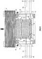
- figure 2 is a vertical cross-section view of the shaping station;
- figure 3 is a top view of the glass support plane and the stops;
- figure 4 is a vertical cross-section view of the device for producing the air bed;
- figure 5 is a longitudinal cross-section view of the shuttle device for conveying the shaped sheet of glass from the shaping station to the tempering station;
- figure 6 is a vertical cross-section view of the shaping station according to an alternative embodiment of the apparatus of the present invention.
- The apparatus comprises a heating furnace 1, a
shaping station 2, atempering station 3 and a delivery station, not shown in the drawings. - According to the present invention the heating furnace 1 brings the glass up to softening temperature, conveying it along a horizontal path formed by a
cylindrical roller bed 4, the movement of which is provided by means of an operating mechanism not shown in the figures. - The
shaping station 2 is situated immediately after the horizontal furnace 1. The shaping station is contained within ahot chamber 12, the walls of which are built of refractory material and which is kept at a temperature of approximately 650°C with the aid of electric heating elements, not shown in the figures. - The control devices for the shaping operation are situated outside the
chamber 12, whereas the equipment performing said shaping is located inside the chamber. - Following immediately the outlet from the furnace 1, on an extension of the roller conveyor for the glass, a
plenum 5 is arranged within thehot chamber 12, the plenum being fed by hot air through atube 6 and supporting a plurality ofnozzles 7, arranged in a suitable size and number. - The group of
nozzles 7 generates a supporting air bed which forms an extension of the glass conveyor formed byrollers 4. The air bed also has a flat surface. - A bearing
frame 8 supports theplenum 5 within thehot chamber 12. Theframe 8 has twohinges 9 close to the outlet from the furnace 1 and on the opposite side twomechanical jacks 10, moved by means ofmotor 11, which can incline the surface of the feeder plenum by 1°-2° with respect to the horizontal. - When the sheet of glass V is on the air bed, the
plenum 5 inclines downward, assisting the glass to slide and giving perfect adhesion of the edge of said glass againstreference stops 45. - The
plenum 5, preferably made of stainless steel, has on its upper plate 51 a plurality of threadedbores 52, arranged density so as not to compromise the resistance of the plate, but at the same time allowing optimum arrangement of the nozzles according to the geometrical form of the sheet of glass to be shaped. - The
nozzles 7 have a first threadedcylindrical portion 53, to allow them to be screwed into theplate 51 of theplenum 5, a second cylindrical portion 54 and athird portion 55 with a substantially frusto-conical shape, and they are preferably made of stainless steel, given that the temperature in the hot chamber of the shaping station is between 600 and 700°C. - According to a preferred embodiment of the invention the internal geometry of the nozzle, capable of allowing a suitable passage of air, is made up of a
first converging channel 56, a successive cylindrical portion withcalibrated cross-section 57, acylindrical channel 58 with a larger diameter than the preceding portion, acylindrical channel 59 with a larger diameter than the precedingchannel 58 and a final frusto-conical part 60 to provide final slowing of the fluid. - The
cylindrical portion 57 has preferably a diameter from 2 to 8 millimeters. - The diameter of the outlet section of the
nozzle 7 is preferably 40 to 100 millimeters. - The
nozzles 7 are arranged on theplenum 5 at the vertexes of a square mesh with a pitch such as to guarantee the desired air discharge space. - In the areas left without nozzles to allow passage of the shaping
ring 24 thebores 52 are closed by means of threadedplugs 61. - On the side walls of the hot chamber openings are formed, said openings being necessary for maintenance and inspection purposes; furthermore an
opening 13 allows the glass to enter the chamber and anotheropening 14 allows said glass to leave it. - To avoid heat losses, said opening 14 is provided with a
drop gate 15 which opens in cycle to permit the entry and exit of ashuttle 16. - The upper shaping
mold 17 is formed by afull mold 18, shaped and provided with a perforated plane, so as to produce a vacuum effect resulting in a suction of the glass V, the vacuum being produced using a Venturi system, not shown in the figure, which ejects the air sucked up through atube 25. - The
mold 17 is anchored to twosupport rods 19 which come out of thehot chamber 12 throughpassages 20 made in the refractory material of the ceiling thereof, and which are connected to amobile frame 21, in its turn moved vertically by anoperating mechanism 23 and a digitally controlledmotor 22. - The vertical movement of the upper mold provides the position of the mold itself to be registered in correspondence with the shaping
ring 24. - An operating mechanism made up of
chains 26 and motor-winch 27 provides to lift the mobile part of the mold, so as to facilitate its extraction when changing equipment. - The
hollow shaping ring 24 is supported byties 33 so as to perform a vertical movement within thehot chamber 12 by means of an operating mechanism and a motor not shown in the figures. - The
device 16 performing a reciprocating horizontal transfer of the sheet of glass to the tempering station from the shaping station, commonly known as a shuttle, has at one of its extremities ahollow ring 34 to house the sheet of glass V and support it during the quenching phase; preferably, unloading of the sheets of glass takes place in the same station, making use of a pressure differential between the upper and the lower blower, pushing the glass upward so that it leaves thering 34, which is thus able to go back and load another sheet of glass. - A
support structure 29 supports drivingscrews 30, to whichlongitudinal guides 28 with an upturned V cross-section are fixed. Wheels 31 are engaged with the V-shaped guides and support theshuttle 16, which is made up of two independent side sections kept parallel by the engagement of the drivingscrews 30.- A rack guided
system 35 with a parallel bar prevents oscillation during the horizontal movement. - The reciprocating horizontal movement of the mold-bearing
shuttle 16 is generated by means of the driving screws 30 engaged withroller wheels 38 connected to the side sections of the shuttle itself and pressing elastically on the thread of thescrews 30. The driving screws are two in number, one on each side of the machine, and they are counter-rotating and have right--and left-handed threads, respectively. - The
screws 30 are supported at their ends by self-aligningroller bearings 32. - The
screws 30 are activated by means of atoothed belt gear 39. - The group of
stops 50 receives the glass V when it leaves the furnace, slowing said glass down progressively as it rests on the air bed formed by thenozzles 7. - Two
support structures 41, one on each side of the machine, hinged at 42, support thecarriages 43 which are moved by a digitally controlled motor not shown in the figures. - The
stop rods ceramic wheels 45; the rods themselves are slightly flexible, so as to adapt to the position of theplane 5 which can be inclined by 1 or 2 degrees. - The sheet of glass V is heated to its softening point in the furnace 1 as it is carried by the
roller bed 4; subsequently, after leaving the roller bed, conveyed on an air hearth bed it is delivered to a first pair ofrods 44 which, extending from thecarriages 43, come into contact with the front edge of the sheet of glass V and slow it down, running along guides 41, situated at the side and outside thehot chamber 12, until stopping the sheet of glass in a suitable position defined by the shaping ring positioned below the floating plane. - A second pair of
rods 48, extending from thecarriages 43, intervenes from the sides to center and position the sheet of glass with respect to the shapingring 24, which is situated below the floating plane. - At the moment in which the sheet of glass has been finally centered, the
ring 24 rises, taking up the sheet of glass V and conveying it towards the shapingmold 18 until it is at a distance such as to allow the vacuum created by the mold by means of its perforated plane to attract the sheet of glass V, which thus continues to bend, taking on the desired shape. - In the meantime the
hollow shaping ring 24 returns below the floating plane of the sheet of glass ready to repeat the cycle. - When shaping has been completed, the
mold 18 releases the sheet of glass onto thering 34 of theshuttle 16, which has positioned itself in the meantime under themold 18, and the shuttle moves rapidly toward the temperingstation 3 which contains oppositeupper nozzles 46 andlower nozzles 47 that perform quenching of the shaped glass V, and which preferably also performs unloading of the glass. - After this the
shuttle 16 with thering 34 return to the shapingstation 2, positioning themselves once more under themold 18 to collect another sheet of glass to be tempered. - According to an alternative embodiment of the apparatus according to the present invention, shown in figure 6, the air hearth bed is generated by
nozzles 7 fed by two separate andadjacent plenums - The plenums rest on
hinges 65 placed close to the vertical walls of thehot chamber 12 and on asingle strut 64, preferably situated at the vertical axis of symmetry of the shaping station, thehinges 65 belonging to thesupport frame 8 which is capable of inclining in the direction of movement of the sheet of glass. Stops 66 run onguides 67 connected to the twoplenums - The
strut 64 rests on abar 68 capable of being lifted bymechanical jacks 69 moved by themotor 70, and it is suitably hinged to thebar 68. - The vertical lifting movement of the
strut 64, shown in the figure in its resting position, is such as to allow the two plenums and therefore the air bed to incline by 1° - 2°. - By this solution an air bed is obtained which is efficient both when producing large sheets of glass occupying a substantial part of the air bed itself, and also when producing smaller sheets of glass which are worked side-by-side in pairs.
- In the latter case, in fact, the two sheets of glass are brought up against the head stops, not shown in the figure, by means of a downward inclination of the two
plenums strut 64, which inclines the two plenums by 1° - 2° in a transversal direction with respect to the direction of movement of the glass, so as to slide the sheets against the side stops and thus position them exactly with respect to the shaping rings 24. - The advantage of this embodiment consists mainly in the fact that the manufacturing apparatus becomes capable of producing sheets of glass of varying sizes without having to change the air bed plane, thus obtaining a notable reduction in costs.
Claims (12)
- An apparatus for shaping and tempering a glass sheet (V) for use in a motor vehicle, comprisinga heating station including a horizontal furnace (1),a shaping station (2) positioned downstream of said heating station including an air bed means and an upper shaping mold (17) having a perforated shaping surface and a vacuum means for creating suction through said perforated shaping surface to attract the glass sheet thereto,a tempering station (3) positioned downstream of said shaping station and including tempering nozzle means for rapidly cooling the glass sheet,a first glass supporting ring (24) for supporting the glass sheet, said glass supporting ring (24) being movable vertically from a position below said air bed means;ring moving means (16) for moving said glass supporting ring vertically toward said perforated shaping surface of said upper shaping mold and for moving said glass suppporting ring horizontally from said shaping station toward said tempering station,
characterised in that it comprisesa roller conveyor (4) extending horizontally through said furnace for feeding the glass sheet in a downstream direction through said furnace along a predetermined path;said shaping station including said bed means in a position immediately adjacent to said roller conveyor and having a supporting surface of flat configuration for supporting the glass sheet at a floating level on said air bed;said first glass supporting ring (24) being mounted in said shaping station for vertical movement between a lowered position below said floating level and a raised position closer to said perforated shaping surface of said upper shaping mold (17) relative to said lowered position;a second glass supporting ring (34) for supporting the glass sheet;ring moving means (16) for moving said second glass supporting ring horizontally from said shaping station toward said tempering station; andsaid air bed means comprise an air plenum (5) and a plurality of upwardly directed air nozzles (7) individually removable supported by said plenum and in fluid communication with said plenum to allow air to be supplied through said nozzles from said plenum to form said air bed, said plenum having a ring-shaped area devoid of said nozzles, said ring shaped area corresponding to a shape of said glass supporting ring (24) to be positioned in said ring-shaped area below said floating level, and said air nozzles (7) being higher than the thickness and/or the radius of curvature of said glass supporting ring (24) to allow said ring to be positioned below said floating level of said air bed. - An apparatus as claimed in claim 1, wherein said shaping section further includes a frame (8) supporting said plenum (5), a first end of said frame being mounted on a pair of hinges (9) and a second end of said frame being mounted on mechanical jacks (10) for allowing said plenum and said air bed to be inclined downwardly in said downstream direction.
- An apparatus as claimed in claim 2, wherein said shaping section further includes a stop means (50) for stopping the glass sheet in a predetermined position on said air bed aligned above said glass support ring (24) when said glass support ring is in said position below said floating level, said stop means comprising a first pair of reference stops (45), each including a cylinder (43) and a rod (44) extending therefrom to contact a front edge of the glass sheet, and a second pair of reference stops (45), each including a cylinder (43) and a rod (48) extending therefrom to contact a side edge of the glass sheet.
- An apparatus as claimed in claim 1, wherein each of said air nozzles (7) is mounted to said plenum by screw threads (53) and includes an upwardly converging channel (56) in communication with said plenum (5), a first cylindrical portion (57) extending from said upwardly converging channel and having a first predetermined cross section for causing a substantially constant air flow rate, a second cylindrical portion (58) extending from said first cylindrical portion and having a second predetermined cross section larger than said first predetermined cross section, and a final frustoconically shaped portion (60) extending from said second cylindrical portion for reducing the air flow rate and forming a portion of said air bed.
- An apparatus as claimed in claim 4, wherein each of said air nozzles further includes an upwardly diverging portion between said first and second cylindrical portions.
- An apparatus as claimed in claim 1, wherein each of said nozzles (7) includes a portion (57) having a cross-sectional diameter of 2 to 8 millimeters.
- An apparatus as claimed in claim 1, wherein each of said nozzles has an air outlet with a cross-sectional diameter of 40 to 100 millimeters.
- An apparatus as claimed in claim 1, wherein said air bed means includes a means for supplying air to said air nozzles at a pressure of 50 to 100 millibar.
- An apparatus as claimed in claim 1, wherein said plenum includes a plurality of threaded nozzle engaging means (52) for removably engaging said plurality of air nozzles and fluidically communicating said nozzles with said plenum.
- An apparatus as claimed in claim 9, further comprising threaded plugs (61), removably engaged with ones of said threaded nozzle engaging means (52) disposed in said ring-shaped area, for preventing air from escaping from said plenum through said ones of said threaded nozzle engaging means disposed in said ring-shaped area.
- An apparatus as recited in claim 10, wherein said threaded nozzle engaging means (52) respectively comprise internally threaded bores;each of said nozzles includes an externally threaded cylindrical portion (53) engageable in one of said bores; andeach of said threaded plugs (61) comprises an externally threaded plug engageable in one of said bores.
- An apparatus as claimed in any one of the preceding claims, characterized in that it comprisessaid shaping station including a pair of air bed means for supporting one or two glass sheets (V) at said floating level on a pair of air beds (63) downstrream of said roller conveyor along said predetermined path;a pair of said first glass supporting ring (24) for supporting the glass sheets;said plenums (62) being positioned adjacent one another and symmetrically about a vertical axis of symmetry of said shaping station; anda vertically mobile strut (64) arranged on said vertical axis of symmetry of said shaping station and supports inner ends of said plenums, outer ends of said plenums being supported on hinges (65), respectively, such that said plenums are capable of inclination in a transverse direction with respect to said predetermined path.
Applications Claiming Priority (2)
| Application Number | Priority Date | Filing Date | Title |
|---|---|---|---|
| ITRM910505 | 1991-07-10 | ||
| ITRM910505AIT1250082B (en) | 1991-07-10 | 1991-07-10 | APPARATUS AND PROCEDURE FOR THE MANUFACTURE OF GLASSES WITH A COMPLEX SHAPE SUITABLE FOR USE ON VEHICLES |
Publications (3)
| Publication Number | Publication Date |
|---|---|
| EP0523016A2 EP0523016A2 (en) | 1993-01-13 |
| EP0523016A3 EP0523016A3 (en) | 1993-08-25 |
| EP0523016B1true EP0523016B1 (en) | 1997-01-22 |
Family
ID=11400254
Family Applications (1)
| Application Number | Title | Priority Date | Filing Date |
|---|---|---|---|
| EP92830363AExpired - LifetimeEP0523016B1 (en) | 1991-07-10 | 1992-07-09 | Apparatus for the manufacture of sheets of glass having a complex shape, for use in motor vehicles |
Country Status (8)
| Country | Link |
|---|---|
| US (1) | US5336288A (en) |
| EP (1) | EP0523016B1 (en) |
| JP (1) | JPH0737328B2 (en) |
| CA (1) | CA2073384A1 (en) |
| DE (1) | DE69216924T2 (en) |
| ES (1) | ES2097898T3 (en) |
| IT (1) | IT1250082B (en) |
| RU (1) | RU2083512C1 (en) |
Cited By (2)
| Publication number | Priority date | Publication date | Assignee | Title |
|---|---|---|---|---|
| US7866186B2 (en) | 2003-03-28 | 2011-01-11 | Pilkington Automotive Deutschland Gmbh | Device for producing a gas cushion |
| US8448466B2 (en) | 2003-03-28 | 2013-05-28 | Pilkington Automotive Deutschland Gmbh | Process and plant for the treatment of the glass sheets of an asymmetric glass-sheet pair |
Families Citing this family (18)
| Publication number | Priority date | Publication date | Assignee | Title |
|---|---|---|---|---|
| IT1250081B (en)* | 1991-07-10 | 1995-03-30 | Siv Soc Italiana Vetro | EQUIPMENT AND PROCEDURE FOR THE MANUFACTURE OF COMPLEX SHAPED GLASS |
| US5411617A (en)* | 1993-04-26 | 1995-05-02 | Hughes Aircraft Company | Method for use in fabricating and/or testing a thin mirror |
| US5403369A (en)* | 1993-09-13 | 1995-04-04 | Glasstech, Inc. | Apparatus and method for positioning glass sheets |
| US5498275A (en)* | 1993-10-18 | 1996-03-12 | Glasstech, Inc. | Glass sheet bending apparatus |
| DE10062954B4 (en)* | 2000-12-16 | 2004-04-15 | Schott Glas | Device for producing glass gobs |
| JP2002293561A (en)* | 2001-04-02 | 2002-10-09 | Asahi Glass Co Ltd | Method and apparatus for bending glass plate |
| ITMI20021146A1 (en)* | 2002-05-28 | 2003-11-28 | Smart Srl | INTRODUCTION DEVICE PARTICULARLY FOR AUTOMATIC ROLLING MACHINES |
| ITMI20021573A1 (en)* | 2002-07-17 | 2004-01-19 | Smart Srl | METHOD FOR THE INTRODUCTION OF BLINDS TO BE THREADED IN AUTOMATIC ROTARY ROLLING MACHINES AND MACHINE WORKING WITH SUCH METHOD |
| DE10305422B4 (en)* | 2003-02-05 | 2006-01-19 | Schott Ag | Method for producing viscous glass balls of viscous glass |
| KR101216416B1 (en)* | 2005-10-24 | 2012-12-28 | 글래스텍 인코포레이티드 | Glass sheet lift jet nozzle delivery and job switching |
| RU2393123C2 (en)* | 2005-10-24 | 2010-06-27 | Гласстек, Инк | Movement of glass sheets using hoisting jet nozzle and switching operations |
| JP2006160604A (en)* | 2006-02-10 | 2006-06-22 | Bando Kiko Co Ltd | Glass sheet working machine |
| JP2010138071A (en)* | 2010-03-16 | 2010-06-24 | Bando Kiko Co Ltd | Apparatus for processing glass sheet |
| US9617181B2 (en) | 2015-07-27 | 2017-04-11 | Glaston Finland Oy | Method of heating a glass sheet for tempering |
| TWI753864B (en) | 2015-11-02 | 2022-02-01 | 美商玻璃技術股份有限公司 | Mold shuttle positioning system for a glass sheet forming system |
| TWI752922B (en) | 2015-11-02 | 2022-01-21 | 美商玻璃技術股份有限公司 | Vacuum mold shuttle system for a glass sheet forming system |
| FR3059318B1 (en)* | 2016-11-30 | 2021-04-02 | Saint Gobain | THIN GLASS BOMBAGE |
| JP6723532B2 (en)* | 2018-03-30 | 2020-07-15 | 坂東機工株式会社 | Glass plate punching device |
Family Cites Families (19)
| Publication number | Priority date | Publication date | Assignee | Title |
|---|---|---|---|---|
| US3223501A (en)* | 1962-05-18 | 1965-12-14 | Pittsburgh Plate Glass Co | Method and apparatus for treating glass on a pressurized fluid bed |
| US3468645A (en)* | 1966-05-09 | 1969-09-23 | Permaglass | Method and apparatus for shaping glass sheets supported on a gas support bed |
| US3846104A (en)* | 1973-01-10 | 1974-11-05 | Ppg Industries Inc | Handling glass sheets for shaping and cooling |
| US3869271A (en)* | 1973-07-26 | 1975-03-04 | Ppg Industries Inc | Shaping glass sheets |
| JPS5421845A (en)* | 1977-07-20 | 1979-02-19 | Ricoh Co Ltd | Control method for copier |
| CA1120726A (en)* | 1978-05-01 | 1982-03-30 | Harold A. Mcmaster | Apparatus and method for bending glass |
| US4285715A (en)* | 1978-10-25 | 1981-08-25 | Ppg Industries, Inc. | Cycle of mold movement while press bending glass sheets |
| US4204853A (en)* | 1978-11-13 | 1980-05-27 | Ppg Industries, Inc. | Glass sheet alignment means and method of using |
| US4432782A (en)* | 1982-06-17 | 1984-02-21 | Ppg Industries, Inc. | Support for hot glass sheets of non-rectangular outline prior to bending |
| US4508556A (en)* | 1984-06-04 | 1985-04-02 | Ppg Industries, Inc. | Method and apparatus for bending glass sheets to complicated shapes including an S-shaped transverse bend |
| US4596592A (en)* | 1985-05-02 | 1986-06-24 | Ppg Industries, Inc. | Stop members for glass sheet shaping molds |
| JPS6234968U (en)* | 1985-08-15 | 1987-03-02 | ||
| US4767437A (en)* | 1987-03-25 | 1988-08-30 | Ppg Industries, Inc. | Horizontal press bending using a splitting vacuum/pressure pickup |
| DE3819503C1 (en)* | 1988-06-08 | 1989-07-20 | Vegla Vereinigte Glaswerke Gmbh, 5100 Aachen, De | |
| JPH06414Y2 (en)* | 1988-08-03 | 1994-01-05 | 日本板硝子株式会社 | Sheet glass bending equipment |
| US4883526A (en)* | 1989-03-30 | 1989-11-28 | Libbey-Owens-Ford Co. | Method and apparatus for shaping and conveying glass sheets |
| DE3928968C1 (en)* | 1989-09-01 | 1991-01-17 | Vegla Vereinigte Glaswerke Gmbh, 5100 Aachen, De | |
| US5066321A (en)* | 1990-07-19 | 1991-11-19 | Glasstech, Inc. | Device for positioning hot glass sheets |
| FR2678261B1 (en)* | 1991-06-27 | 1994-10-21 | Saint Gobain Vitrage Int | METHOD AND DEVICE FOR BOMBING A GLASS SHEET. |
- 1991
- 1991-07-10ITITRM910505Apatent/IT1250082B/enactiveIP Right Grant
- 1992
- 1992-07-08CACA002073384Apatent/CA2073384A1/ennot_activeAbandoned
- 1992-07-09RUSU925052157Apatent/RU2083512C1/enactive
- 1992-07-09EPEP92830363Apatent/EP0523016B1/ennot_activeExpired - Lifetime
- 1992-07-09ESES92830363Tpatent/ES2097898T3/ennot_activeExpired - Lifetime
- 1992-07-09DEDE69216924Tpatent/DE69216924T2/ennot_activeExpired - Fee Related
- 1992-07-09JPJP4182466Apatent/JPH0737328B2/ennot_activeExpired - Lifetime
- 1992-07-10USUS07/911,940patent/US5336288A/ennot_activeExpired - Fee Related
Cited By (2)
| Publication number | Priority date | Publication date | Assignee | Title |
|---|---|---|---|---|
| US7866186B2 (en) | 2003-03-28 | 2011-01-11 | Pilkington Automotive Deutschland Gmbh | Device for producing a gas cushion |
| US8448466B2 (en) | 2003-03-28 | 2013-05-28 | Pilkington Automotive Deutschland Gmbh | Process and plant for the treatment of the glass sheets of an asymmetric glass-sheet pair |
Also Published As
| Publication number | Publication date |
|---|---|
| ITRM910505A0 (en) | 1991-07-10 |
| CA2073384A1 (en) | 1993-01-11 |
| EP0523016A2 (en) | 1993-01-13 |
| JPH0737328B2 (en) | 1995-04-26 |
| DE69216924D1 (en) | 1997-03-06 |
| EP0523016A3 (en) | 1993-08-25 |
| JPH05193966A (en) | 1993-08-03 |
| DE69216924T2 (en) | 1997-05-22 |
| US5336288A (en) | 1994-08-09 |
| ITRM910505A1 (en) | 1993-01-10 |
| ES2097898T3 (en) | 1997-04-16 |
| IT1250082B (en) | 1995-03-30 |
| RU2083512C1 (en) | 1997-07-10 |
Similar Documents
| Publication | Publication Date | Title |
|---|---|---|
| EP0523016B1 (en) | Apparatus for the manufacture of sheets of glass having a complex shape, for use in motor vehicles | |
| US4229200A (en) | Drop forming glass sheets with auxiliary shaping means | |
| CN1037260C (en) | Method and apparatus for bending a glass sheet in a horizontal position | |
| US4883526A (en) | Method and apparatus for shaping and conveying glass sheets | |
| US4282026A (en) | Apparatus for bending and tempering glass | |
| US4285715A (en) | Cycle of mold movement while press bending glass sheets | |
| CA1120725A (en) | Apparatus for bending and tempering glass | |
| US5833729A (en) | Method and apparatus for bending glass sheets | |
| JPS6359973B2 (en) | ||
| JPH03150232A (en) | Method and device for bending glass pane | |
| JPS5924090B2 (en) | How to form a glass plate | |
| FI58623B (en) | ANORDNING FOER BOEJNING AV VAERMEUPPMJUKADE GLASSKIVOR | |
| EP0523017B1 (en) | Apparatus and process for the manufacture of sheets of glass having a complex shape | |
| US4233049A (en) | Method and apparatus for shaping glass sheets by drop forming | |
| US4339259A (en) | Process and apparatus for bending and tempering glass sheets, especially thin sheets | |
| JPS5943427B2 (en) | Glass sheet forming method and device | |
| US4298368A (en) | Delivering and aligning glass sheets in a bending station | |
| US4842634A (en) | Method and apparatus for curving a glass sheet | |
| EP0164823B1 (en) | Apparatus for bending glass sheets | |
| US4300935A (en) | Shaping glass sheets by drop forming with improved sag control | |
| US4280828A (en) | Shaping glass sheets by drop forming with pressure assist | |
| KR950000622B1 (en) | Transfer of glass panes for bending them | |
| RU2081067C1 (en) | Apparatus for molding and tempering glass sheets | |
| US4830649A (en) | Method & apparatus for bending glass sheets | |
| US4364765A (en) | Apparatus and method for handling heated glass sheets |
Legal Events
| Date | Code | Title | Description |
|---|---|---|---|
| PUAI | Public reference made under article 153(3) epc to a published international application that has entered the european phase | Free format text:ORIGINAL CODE: 0009012 | |
| AK | Designated contracting states | Kind code of ref document:A2 Designated state(s):BE DE ES FR GB LU NL | |
| PUAL | Search report despatched | Free format text:ORIGINAL CODE: 0009013 | |
| AK | Designated contracting states | Kind code of ref document:A3 Designated state(s):BE DE ES FR GB LU NL | |
| 17P | Request for examination filed | Effective date:19940222 | |
| 17Q | First examination report despatched | Effective date:19951023 | |
| GRAG | Despatch of communication of intention to grant | Free format text:ORIGINAL CODE: EPIDOS AGRA | |
| GRAH | Despatch of communication of intention to grant a patent | Free format text:ORIGINAL CODE: EPIDOS IGRA | |
| GRAH | Despatch of communication of intention to grant a patent | Free format text:ORIGINAL CODE: EPIDOS IGRA | |
| GRAA | (expected) grant | Free format text:ORIGINAL CODE: 0009210 | |
| AK | Designated contracting states | Kind code of ref document:B1 Designated state(s):BE DE ES FR GB LU NL | |
| REF | Corresponds to: | Ref document number:69216924 Country of ref document:DE Date of ref document:19970306 | |
| REG | Reference to a national code | Ref country code:ES Ref legal event code:FG2A Ref document number:2097898 Country of ref document:ES Kind code of ref document:T3 | |
| ET | Fr: translation filed | ||
| PLBE | No opposition filed within time limit | Free format text:ORIGINAL CODE: 0009261 | |
| 26N | No opposition filed | ||
| PGFP | Annual fee paid to national office [announced via postgrant information from national office to epo] | Ref country code:NL Payment date:19990727 Year of fee payment:8 | |
| PGFP | Annual fee paid to national office [announced via postgrant information from national office to epo] | Ref country code:GB Payment date:20000705 Year of fee payment:9 | |
| PGFP | Annual fee paid to national office [announced via postgrant information from national office to epo] | Ref country code:LU Payment date:20000710 Year of fee payment:9 Ref country code:DE Payment date:20000710 Year of fee payment:9 | |
| PGFP | Annual fee paid to national office [announced via postgrant information from national office to epo] | Ref country code:FR Payment date:20000711 Year of fee payment:9 | |
| PGFP | Annual fee paid to national office [announced via postgrant information from national office to epo] | Ref country code:ES Payment date:20000719 Year of fee payment:9 | |
| PGFP | Annual fee paid to national office [announced via postgrant information from national office to epo] | Ref country code:BE Payment date:20000918 Year of fee payment:9 | |
| PG25 | Lapsed in a contracting state [announced via postgrant information from national office to epo] | Ref country code:NL Free format text:LAPSE BECAUSE OF NON-PAYMENT OF DUE FEES Effective date:20010201 | |
| NLV4 | Nl: lapsed or anulled due to non-payment of the annual fee | Effective date:20010201 | |
| PG25 | Lapsed in a contracting state [announced via postgrant information from national office to epo] | Ref country code:LU Free format text:LAPSE BECAUSE OF NON-PAYMENT OF DUE FEES Effective date:20010709 Ref country code:GB Free format text:LAPSE BECAUSE OF NON-PAYMENT OF DUE FEES Effective date:20010709 | |
| PG25 | Lapsed in a contracting state [announced via postgrant information from national office to epo] | Ref country code:ES Free format text:LAPSE BECAUSE OF NON-PAYMENT OF DUE FEES Effective date:20010710 | |
| PG25 | Lapsed in a contracting state [announced via postgrant information from national office to epo] | Ref country code:BE Free format text:LAPSE BECAUSE OF NON-PAYMENT OF DUE FEES Effective date:20010731 | |
| BERE | Be: lapsed | Owner name:SOCIETA' ITALIANA VETRO- SIV-S.P.A. Effective date:20010731 | |
| GBPC | Gb: european patent ceased through non-payment of renewal fee | Effective date:20010709 | |
| PG25 | Lapsed in a contracting state [announced via postgrant information from national office to epo] | Ref country code:FR Free format text:LAPSE BECAUSE OF NON-PAYMENT OF DUE FEES Effective date:20020329 | |
| PG25 | Lapsed in a contracting state [announced via postgrant information from national office to epo] | Ref country code:DE Free format text:LAPSE BECAUSE OF NON-PAYMENT OF DUE FEES Effective date:20020501 | |
| REG | Reference to a national code | Ref country code:FR Ref legal event code:ST | |
| REG | Reference to a national code | Ref country code:ES Ref legal event code:FD2A Effective date:20020810 |