EP0522735B1 - Locking dilator for peel away introducer sheath - Google Patents
Locking dilator for peel away introducer sheathDownload PDFInfo
- Publication number
- EP0522735B1 EP0522735B1EP92305717AEP92305717AEP0522735B1EP 0522735 B1EP0522735 B1EP 0522735B1EP 92305717 AEP92305717 AEP 92305717AEP 92305717 AEP92305717 AEP 92305717AEP 0522735 B1EP0522735 B1EP 0522735B1
- Authority
- EP
- European Patent Office
- Prior art keywords
- dilator
- introducer sheath
- handle
- peel away
- gripping clamp
- Prior art date
- Legal status (The legal status is an assumption and is not a legal conclusion. Google has not performed a legal analysis and makes no representation as to the accuracy of the status listed.)
- Expired - Lifetime
Links
- 238000000034methodMethods0.000description18
- 230000007246mechanismEffects0.000description15
- 230000005012migrationEffects0.000description9
- 238000013508migrationMethods0.000description9
- 210000001519tissueAnatomy0.000description8
- 238000003780insertionMethods0.000description6
- 230000037431insertionEffects0.000description6
- 230000008878couplingEffects0.000description5
- 238000010168coupling processMethods0.000description5
- 238000005859coupling reactionMethods0.000description5
- 210000003462veinAnatomy0.000description5
- 239000004033plasticSubstances0.000description4
- 229920003023plasticPolymers0.000description4
- 208000014674injuryDiseases0.000description3
- 230000008733traumaEffects0.000description3
- 210000004204blood vesselAnatomy0.000description2
- 210000001124body fluidAnatomy0.000description2
- 239000010839body fluidSubstances0.000description2
- 208000015181infectious diseaseDiseases0.000description2
- 239000000463materialSubstances0.000description2
- 206010053567CoagulopathiesDiseases0.000description1
- 239000004698PolyethyleneSubstances0.000description1
- 239000004809TeflonSubstances0.000description1
- 229920006362Teflon®Polymers0.000description1
- 208000027418Wounds and injuryDiseases0.000description1
- 230000000712assemblyEffects0.000description1
- 238000000429assemblyMethods0.000description1
- 230000000740bleeding effectEffects0.000description1
- 230000035602clottingEffects0.000description1
- 238000010276constructionMethods0.000description1
- 238000007373indentationMethods0.000description1
- 238000001802infusionMethods0.000description1
- 230000003993interactionEffects0.000description1
- 238000001990intravenous administrationMethods0.000description1
- 238000012423maintenanceMethods0.000description1
- 206010033675panniculitisDiseases0.000description1
- 230000037361pathwayEffects0.000description1
- -1polyethylenePolymers0.000description1
- 229920000573polyethylenePolymers0.000description1
- 210000004304subcutaneous tissueAnatomy0.000description1
- 230000000472traumatic effectEffects0.000description1
Images


Classifications
- A—HUMAN NECESSITIES
- A61—MEDICAL OR VETERINARY SCIENCE; HYGIENE
- A61M—DEVICES FOR INTRODUCING MEDIA INTO, OR ONTO, THE BODY; DEVICES FOR TRANSDUCING BODY MEDIA OR FOR TAKING MEDIA FROM THE BODY; DEVICES FOR PRODUCING OR ENDING SLEEP OR STUPOR
- A61M25/00—Catheters; Hollow probes
- A61M25/01—Introducing, guiding, advancing, emplacing or holding catheters
- A61M25/06—Body-piercing guide needles or the like
- A61M25/0662—Guide tubes
- A61M25/0668—Guide tubes splittable, tear apart
Definitions
- This inventionrelates to invasive medical devices.
- this inventionrelates to a locking dilator associated with a peel away introducer sheath used for the introduction of catheters and other such medical devices into a patient.
- percutaneous methodshave been developed to create small openings in the tissue and then to employ various devices to slightly enlarge the opening to permit the insertion of specialized medical instruments.
- One such device commonly usedis a dilator.
- the dilatorhas a tapered end which will enlarge the opening at the puncture site as the dilator is advanced through the tissue. Once the tissue is enlarged, the dilator is removed and the desired catheter or other medical device is quickly inserted through the opening created.
- This methodis subject to many problems because of trauma, bleeding of the patient and the difficulty of insertion of certain specialized medical instruments in such an opening.
- many types of medical devices, including pacemaker leadsare extremely soft and supple or will damage the body during insertion if not surrounded by some introducing means.
- the introducer sheathmust be made with an internal passageway at least as large as the largest part of the device so that the introducer sheath may be removed following device placement in the body. Further, if such enlarged opening is created in the body, when the thin part of the device is advanced, there will now be much empty space creating a pathway for body fluids to pass around the device and escape from the body increasing the risk of clotting, infection, etc.
- the peel away introducer sheathused in conjunction with a dilator.
- the peel away introducer sheathis a thin-walled, usually cylindrical, device that is placed in position so that it provides a communicating passageway through the tissue. This is often accomplished by fitting the introducer sheath tightly over a dilator, advancing both devices through the tissue together as a unit, and then removing the dilator from inside the introducer sheath, leaving the introducer sheath alone in the desired position, acting to hold the penetrated site open. At that point, the catheter tube or other invasive device is advanced through the introducer sheath into the desired position. The peel away introducer sheath is then removed from the tissue and pulled apart lengthwise into two pieces.
- This capacity for splittingallows the introducer sheath to be made as small as the inner compartmental portion of the inserted medical device.
- the introducer sheathis then pulled apart and removed.
- Proximal handles on the introducer sheathare generally provided to facilitate grasping of the introducer sheath halves.
- U.S. Patent No. 4,983,168discloses a layered peel away hollow sheath wherein the sheath wall is comprised of at least two layers, the inside layer being cylindrical and the outside layer comprising two semi-cylindrical segments defining opposed axially-directed slits or slots there between which comprise tear lines such that the sheath manually tears axially along the single layered tear line into two pieces for removal of the sheath from around the indwelling device.
- U.S. Patent No. 4,596,559discloses a tear away introducer tool for use with a disposable introducer set in conjunction with a catheter.
- the tear away introduceris comprised of an elongated sheath having a pair of opposed splits in the proximal end which define a pair of tabs.
- a handleis secured to the sheath and includes a pair of handle members, each comprising a pair of clamping elements which clamp the tabs of the sheath there between.
- the handlehas opposed weakened portions which facilitate the tearing of the sheath along axial lines.
- U.S. Patent No. RE 31,855discloses a sheath that has an internal molecular orientation which tears easily in a lengthwise direction and with great difficulty in a cross-wise or oblique directions. See also U.S. Patent No. 4,581,025.
- U.S. Patent Nos. 4,166,469, 4,243,050, 4,345,606 and 4,451,256disclose sheaths longitudinally scored or perforated on opposite sides. This results in a cylindrical sheath with two weakened lines which run lengthwise on opposite sides of the cylinder. The introducer or sheath is thus mechanically weakened along its scored or perforated regions and less resistant to tearing than the rest of the sheath cylinder, causing the tear once started to propagate along the weakened region. See also U.S. Patent No. 4,451,256.
- U.S. Patent No. 4,772,266Incorporated in the proximal end of the dilator is a female coupling element, the interior of which comprises a helically directed luer loc mechanism.
- the proximal end of the introducer sheathcontains a male luer loc coupling member which works in combination with the female coupling member of the dilator.
- the female coupling memberis axially rotated around the male coupling member of the introducer sheath, the dilator and the introducer sheath are releasably locked in position.
- This deviceis cumbersome to the medical practitioner considering that the practitioner is gloved and manipulation of the device is difficult.
- U.S. Patent No. 4,362,156discloses an intravenous infusion assembly wherein a catheter assembly and a needle assembly are releasably locked together at their proximal ends to prevent relative axial movement there between during insertion into the vein.
- Clamp armsare an element of the needle assembly wherein said clamp arms contain hooks which engage the lugs on the catheter assembly.
- Operating in conjunction with the clamp arm and hookare an interfitting tenon on the needle assembly and a notch on the catheter assembly. The combination of all of these elements when interlocked are required to limit relative rotation between the needle assembly and the catheter assembly.
- Another method of preventing the migration of the dilator within the introducer sheathis an interlocking mechanism manufactured by Angeion as disclosed in Journal of Invasive Cardiology, Vol. 1, No. 5, p. 249 (1991) and Angeion advertising material of 1991.
- This mechanismis a one piece device containing an arm which fits below the handle of the introducer sheath and a slotted portion which is secured on the proximal end of the dilator.
- the present inventionprovides a dilator and introducer sheath locking system comprised of a dilator containing an elongated dilator cannula with a tapered distal end, a gripping clamp secured to its proximal end and a peel away introducer sheath with a tapered distal end and a proximal end containing a splittable handle which interacts with the gripping clamp of the dilator to prevent undesired rearward migration of the dilator within the introducer sheath.
- a dilator and peel away introducer sheath assembly(10) comprising
- This locking dilator and peel away introducer sheath systemprovides an easy to use, safe method of inserting the introducer and dilator into a patient while maintaining a stable relationship between the dilator and introducer sheath during such introduction. Because of its unique locking mechanism, undesired rearward migration of the dilator within the introducer sheath is eliminated.
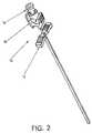
- a locking dilator with peel away introducer sheath system(10) comprised of a peel away introducer sheath (12) used in combination with a dilator (14) containing a gripping clamp mechanism (16) for securing the dilator (14) and the introducer sheath (12) together to prevent rearward migration of the dilator within the introducer sheath.
- a gripping clamp mechanism (16)for securing the dilator (14) and the introducer sheath (12) together to prevent rearward migration of the dilator within the introducer sheath.
- the dilator and introducer sheathare components of an introducer set which commonly includes a disposable syringe, a hollow hypodermic needle for use with the syringe and a wire guide. These products may also be used in other generally accepted introducer placement techniques.
- the introducer sheath (12)is a generally elongated substantially cylindrical tube (18) having a handle (20) affixed to the proximal end thereof. See Figures 3 and 4.
- the tube (18)is formed of a suitable plastic, preferably a teflon ® or polyethylene type plastic, wherein said plastic is compatible with body fluids.
- the tubehas a proximal end (22) and a distal end (24).
- the tubehas a pair of mechanically formed, longitudinally extending zones (26) of reduced thickness defined by internally scored longitudinal shallow grooves (27) or indentations, running throughout the length of the tube. See Figure 1A. These mechanically formed, reduced thickness zones permit the introducer sheath to be "peeled away" following use. Although other methods of splitting the introducer sheath are acceptable and well known, the above referred to method is preferred.
- the handle (20)includes a pair of handle members (30) which project laterally outward from the cylindrically shaped tube engaging said tube (18).
- Each handle member (30)is secured to the proximal end (22) of the introducer sheath by conventional securing methods.
- Each handle member (30)defines one-half of the handle (20).
- Each of the handle members (30)are secured to the tube (18) at such a location to permit the easy splitting of the tube by pressure on the top surface (32) of each of the handle members as they are pulled away from the surface of the tube.
- the top surface (32) of each of the handle membersis ribbed.
- the handle membersare extended, preferably, at least about 1.26 cms (1 ⁇ 2 inch) from the surface of the tube for ease of use.
- the tubeextends proximally to the surface of the handle and creates the dilator opening (34) running the length of the tube through which the dilator can be inserted.
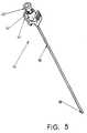
- the dilator (14)includes an elongated tubular portion (36) with a tapered distal end (38) also formed of a suitably compatible plastic material. See Figure 5.
- the external diameter of the tubular portion of the dilatoris of a size sufficient to pass through the dilator opening (34) in the introducer (12).
- a Luer fitting (42)Attached at the proximal end (40) of the dilator is a Luer fitting (42) which is used in combination with other medical instruments.
- This fitting (42)is frequently used by a medical practitioners as a support during insertion of the introducer set.
- the gripping clamp mechanism (16)is comprised of a pair of arms (44) connected by integral hinges (46) to a pair of proximal clamping sides (48) and a gripping clamp body (50).
- the arms (44)project away from the distal end of the dilator and preferably are ribbed on their outside surface.
- the hingesare secured to the gripping clamp body (50) which is preferably tubular in shape and secured by conventional securing means to the Luer fitting (42) of the dilator or may be molded as one piece to the proximal end (40) of the tubular portion (36).
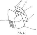
- proximal clamping sides (48)project down the dilator to form the pair of opposite faced parallel clamping sides. These proximal clamping sides (48) will, when properly sited, clamp over the side edges (52) of the handle members (30) of the introducer sheath. See Figure 1. The width of these clamping sides must be sufficient to hold the handle members (30) securely in place. In a preferred embodiment each proximal clamping side (48) will contain a lip (54) to assist in holding the handle members (30) securely in place. See Figure 6. In one embodiment these lips are on the outside edge of the clamping sides (48) and project over the edge of the side edged (54) of the handle members when in use.
- the lipinteracts with a slot (not shown) in the side edge of the handle member to hold securely the handle member.
- a slot (not shown) in the clamping sidesinteracts with a lip (not shown) in the side edge of each handle member to hold the handle member securely in place.
- the pressure of the clamping sides (48) on the handle members (30) and the interaction of the lips (54) of the clamping sides (48) on the side edges (52) of the handle members (30)prevent undesired longitudinal movement of the dilator within the introducer sheath and also prevent the handle members from pulling apart while secured.
- the introducer sheathis removed from its hold by the gripping clamp mechanism (16) by squeezing on the arms (44) of the gripping clamp mechanism (16).
- the vein of a patientis pierced by a hypodermic needle.
- the syringeis removed and a guidewire is threaded through the needle into the vein leaving a portion of the guidewire exposed.
- the needleis thereafter removed from the wire.
- the dilator with gripping clamp (14)is inserted through the dilator opening (34) in the introducer sheath (12) and the handle members (30) are clamped in place by the clamping sides (48) of the gripping clamp mechanism (16).
- the combined dilator and introducer sheathare then advanced as a unit over the guidewire and through the skin incision into the vein.
- the arms (44) of the gripping clamp mechanism (16)are squeezed to disconnect the dilator (14) from the introducer sheath (12).
- the dilator (14) and guidewireare then removed and an appropriate medical device, such as a catheter, is passed into the introducer sheath (12).
- the catheteris advanced through the tube (18) of the introducer sheath into the vein.
- the introducer sheath (12)is withdrawn from the patient.
- the introducer sheathis then removed from the patient by the simultaneous gripping of each of the handle members (30) followed by pulling apart of the tube (18). By pulling the handle members (30) apart, the tube will be split along the zones of reduced thickness (26), resulting in the entire introducer sheath being readily split.
Landscapes
- Health & Medical Sciences (AREA)
- Life Sciences & Earth Sciences (AREA)
- Biophysics (AREA)
- Pulmonology (AREA)
- Engineering & Computer Science (AREA)
- Anesthesiology (AREA)
- Biomedical Technology (AREA)
- Heart & Thoracic Surgery (AREA)
- Hematology (AREA)
- Animal Behavior & Ethology (AREA)
- General Health & Medical Sciences (AREA)
- Public Health (AREA)
- Veterinary Medicine (AREA)
- Media Introduction/Drainage Providing Device (AREA)
Description
Claims (4)
- A dilator and peel away introducer sheath assembly(10) comprising(a) a dilator means (14) comprised of an elongateddilator tube means (36) with a tapered distal end (38)and a dilator fitting (42) secured to the proximal end(40) of the elongated dilator tube means;(b) a peel away introducer sheath means (12) withtapered distal end (24) and a proximal end (22)containing a splittable handle (30) such that theintroducer sheath means (12) may be split along weakenedlines (26) through its entire length, and(c) means for locking the sheath means (12) to thedilator means (14), characterised in that the splittablehandle (30) has side edges (52) which are parallel toeach other and in that the locking means comprisegripping clamp means (16) secured to the said dilatormeans (14), the gripping clamp means (16) being comprisedof a pair of arms (44), integral hinges (46), proximalclamping sides (48) and a gripping clamp body (50),within which the splittable handle (30) is located in thelocked position, the proximal clamping sides (48) beinga pair of opposite faced substantially parallel clampingsides directed toward the distal end of the introducersheath means, adapted to clamp over the side edges (52)of the said splittable handle and engage and secure saidsplittable handle (30) of said introducer sheath means(12) to prevent longitudinal movement and rotationalmovement of the dilator means (14) when secured to theintroducer sheath means (12) by the gripping clamp means(16) and wherein the gripping clamp means (16) whensecured to the introducer sheath means (12) prevent thesplittable handle (30) of said introducer sheath means (12) from splitting.
- The dilator and peel away introducer sheath assemblyof claim 1 wherein each opposite faced substantiallyparallel clamping side (48) contains a lip (54) on itsoutside edge.
- The dilator and peel away introducer sheath assemblyof claim 2 wherein said lips (54) protrude over the sides(52) of the splittable handle (30) to hold said handlesecurely in place when the dilator means (14) andintroducer sheath means (12) are secured together.
- The dilator and peel away introducer sheath assemblyof claim 1, 2 or 3 wherein said splittable handle (30) isreleased by compressing said pair of arms (44) of saidgripping clamp means (16) and sliding said introducersheath means (12) down said dilator means (14).
Applications Claiming Priority (2)
| Application Number | Priority Date | Filing Date | Title |
|---|---|---|---|
| US07/724,405US5098392A (en) | 1991-06-28 | 1991-06-28 | Locking dilator for peel away introducer sheath |
| US724405 | 1991-06-28 |
Publications (2)
| Publication Number | Publication Date |
|---|---|
| EP0522735A1 EP0522735A1 (en) | 1993-01-13 |
| EP0522735B1true EP0522735B1 (en) | 1998-08-19 |
Family
ID=24910310
Family Applications (1)
| Application Number | Title | Priority Date | Filing Date |
|---|---|---|---|
| EP92305717AExpired - LifetimeEP0522735B1 (en) | 1991-06-28 | 1992-06-22 | Locking dilator for peel away introducer sheath |
Country Status (4)
| Country | Link |
|---|---|
| US (1) | US5098392A (en) |
| EP (1) | EP0522735B1 (en) |
| JP (1) | JPH05184683A (en) |
| DE (1) | DE69226684T2 (en) |
Cited By (1)
| Publication number | Priority date | Publication date | Assignee | Title |
|---|---|---|---|---|
| US6689151B2 (en) | 2001-01-25 | 2004-02-10 | Scimed Life Systems, Inc. | Variable wall thickness for delivery sheath housing |
Families Citing this family (176)
| Publication number | Priority date | Publication date | Assignee | Title |
|---|---|---|---|---|
| WO1993008872A1 (en)* | 1991-10-31 | 1993-05-13 | Medtronic, Inc. | Implantable medical device with flexible hardware platform |
| US5672158A (en)* | 1992-01-07 | 1997-09-30 | Sherwood Medical Company | Catheter introducer |
| WO1993020879A1 (en)* | 1992-04-09 | 1993-10-28 | Medtronic, Inc. | Lead introducer with mechanical opening valve |
| US6540764B1 (en)* | 1992-06-02 | 2003-04-01 | General Surgical Innovations, Inc. | Apparatus and method for dissecting tissue layers |
| US6312442B1 (en) | 1992-06-02 | 2001-11-06 | General Surgical Innovations, Inc. | Method for developing an anatomic space for laparoscopic hernia repair |
| US5221263A (en)* | 1992-07-30 | 1993-06-22 | Gesco International, Inc. | Catheter emplacement apparatus |
| US5250033A (en)* | 1992-10-28 | 1993-10-05 | Interventional Thermodynamics, Inc. | Peel-away introducer sheath having proximal fitting |
| ES2105330T3 (en)* | 1992-11-24 | 1997-10-16 | Braun Melsungen Ag | CATHETERIZATION INSTRUMENTAL. |
| USD352108S (en) | 1993-05-07 | 1994-11-01 | The Kendall Company | Splittable epidural needle |
| US5320602A (en)* | 1993-05-14 | 1994-06-14 | Wilson-Cook Medical, Inc. | Peel-away endoscopic retrograde cholangio pancreatography catheter and a method for using the same |
| US5334157A (en)* | 1993-09-09 | 1994-08-02 | Gesco International, Inc. | Catheter introducer |
| US5437645A (en)* | 1993-10-08 | 1995-08-01 | United States Surgical Corporation | Surgical instrument positioning device |
| US5409469A (en)* | 1993-11-04 | 1995-04-25 | Medtronic, Inc. | Introducer system having kink resistant splittable sheath |
| DE69431369T2 (en)* | 1993-12-10 | 2003-05-15 | The Boc Group Plc, Windlesham | venous cannula |
| US5454790A (en)* | 1994-05-09 | 1995-10-03 | Innerdyne, Inc. | Method and apparatus for catheterization access |
| US5639276A (en)* | 1994-09-23 | 1997-06-17 | Rapid Development Systems, Inc. | Device for use in right ventricular placement and method for using same |
| US5536255A (en)* | 1994-10-03 | 1996-07-16 | Moss; Gerald | Dilator/introducer apparatus for percutaneous gastrostomy |
| US5885217A (en)* | 1995-01-20 | 1999-03-23 | Tyco Group S.A.R.L. | Catheter introducer |
| USD378130S (en)* | 1995-03-24 | 1997-02-18 | N.I.T., Inc. | Universal hub for an anesthesia needle |
| US6096022A (en)* | 1995-08-31 | 2000-08-01 | Target Therapeutics Inc. | Bi-directional catheter |
| US5741233A (en)* | 1995-10-20 | 1998-04-21 | Tfx Medical, Incorporated | Introducer device and methods of use thereof |
| US5782807A (en) | 1995-10-20 | 1998-07-21 | Tfx Medical Incorporated | Releasably locking introducer devices |
| US6645178B1 (en) | 1997-04-21 | 2003-11-11 | Larry G. Junker | Apparatus for inserting medical device |
| US6758854B1 (en) | 1997-05-09 | 2004-07-06 | St. Jude Medical | Splittable occlusion balloon sheath and process of use |
| US6083207A (en)* | 1998-12-08 | 2000-07-04 | Daig Corporation | Partitioned hemostasis valve system |
| US6027480A (en)* | 1997-08-11 | 2000-02-22 | Becton Dickinson And Company | Catheter introducer |
| US5951518A (en)* | 1997-10-31 | 1999-09-14 | Teleflex, Incorporated | Introducing device with flared sheath end |
| US6080141A (en)* | 1997-12-22 | 2000-06-27 | Becton, Dickinson And Company | Splittable tubular medical device and method for manufacture |
| US6022342A (en)* | 1998-06-02 | 2000-02-08 | Mukherjee; Dipankar | Catheter introducer for antegrade and retrograde medical procedures |
| WO2001000268A1 (en)* | 1999-06-25 | 2001-01-04 | Daig Corporation | Splittable occlusion balloon sheath and process of use |
| US6382209B1 (en)* | 1999-10-14 | 2002-05-07 | Frederic J Toye | Apparatus and method enabling location of trachea breathing tube in body viscus |
| US6454744B1 (en)* | 1999-12-23 | 2002-09-24 | Tfx Medical, Inc. | Peelable PTFE sheaths and methods for manufacture of same |
| WO2001049363A1 (en) | 1999-12-30 | 2001-07-12 | Cook Vascular Incorporated | Splittable medical valve |
| US6336914B1 (en) | 2000-01-13 | 2002-01-08 | Gillespie, Iii Richard D. | Releasable interlock assembly having axial and rotational engagement |
| USD450839S1 (en) | 2000-02-07 | 2001-11-20 | Larry G. Junker | Handle for introducer sheath |
| US6589262B1 (en) | 2000-03-31 | 2003-07-08 | Medamicus, Inc. | Locking catheter introducing system |
| US6497681B1 (en) | 2000-06-02 | 2002-12-24 | Thomas Medical Products, Inc. | Device and method for holding and maintaining the position of a medical device such as a cardiac pacing lead or other intravascular instrument and for facilitating removal of a peelable or splittable introducer sheath |
| US6558354B1 (en)* | 2000-08-04 | 2003-05-06 | Becton Dickinson And Company | Adapter for connecting an introducer needle assembly to a catheter introducer |
| US7001396B2 (en)* | 2003-03-26 | 2006-02-21 | Enpath Medical, Inc. | Safety introducer assembly and method |
| US6641564B1 (en)* | 2000-11-06 | 2003-11-04 | Medamicus, Inc. | Safety introducer apparatus and method therefor |
| US20040092879A1 (en)* | 2000-11-06 | 2004-05-13 | Medamicus, Inc. | Safety introducer apparatus and method therefor |
| US6582390B1 (en) | 2000-11-08 | 2003-06-24 | Endovascular Technologies, Inc. | Dual lumen peel-away sheath introducer |
| US6994693B2 (en) | 2001-07-17 | 2006-02-07 | Yale University | Tunneler-needle combination for tunneled catheter placement |
| DE60235574D1 (en)* | 2001-12-26 | 2010-04-15 | Univ Yale | VESSEL shunt device |
| US6692464B2 (en) | 2002-02-28 | 2004-02-17 | Cook, Incorporated | T-fitting for splittable sheath |
| US7534250B2 (en)* | 2002-06-28 | 2009-05-19 | Cook Critical Care | Introducer sheath |
| JP4405390B2 (en)* | 2002-08-29 | 2010-01-27 | メデイカル コンポーネンツ,インコーポレーテツド | Dilator and sheath assembly for releasable fixation |
| US7422571B2 (en) | 2002-08-29 | 2008-09-09 | Medical Components, Inc. | Releasably locking dilator and sheath assembly |
| US7300448B2 (en)* | 2002-10-04 | 2007-11-27 | Tyco Healthcare Group Lp | Balloon dissector with cannula |
| JP4546247B2 (en) | 2002-10-04 | 2010-09-15 | タイコ ヘルスケア グループ エルピー | Balloon dissector with cannula |
| EP1585574A4 (en)* | 2002-12-20 | 2006-04-26 | Cardiac Inv S Unltd Inc | Apparatus and method for implanting left ventricular pacing leads within the coronary sinus |
| WO2004069498A2 (en) | 2003-01-31 | 2004-08-19 | Flex Partners, Inc. | Manipulation and cutting system and method |
| US7811293B2 (en)* | 2003-01-31 | 2010-10-12 | Philip J. Simpson | System and method for rapid placement of chest tubes |
| EP1599143B1 (en)* | 2003-01-31 | 2014-01-29 | Simpson, Philip J. | System for rapid placement of chest tubes |
| US7655021B2 (en)* | 2003-03-10 | 2010-02-02 | Boston Scientific Scimed, Inc. | Dilator with expandable member |
| WO2004100799A2 (en)* | 2003-05-08 | 2004-11-25 | Tyco Healthcare Group Lp | Balloon dissector with balloon anchor cannula |
| EP1702415A2 (en)* | 2003-12-23 | 2006-09-20 | Medical Components, Inc. | Graduated sheath and dilator assembly |
| US20050209609A1 (en)* | 2004-02-24 | 2005-09-22 | Board Of Regents, The University Of Texas System | Foreign body retrieval devices |
| US7578803B2 (en)* | 2004-03-18 | 2009-08-25 | C. R. Bard, Inc. | Multifunction adaptor for an open-ended catheter |
| US7854731B2 (en) | 2004-03-18 | 2010-12-21 | C. R. Bard, Inc. | Valved catheter |
| US7094218B2 (en) | 2004-03-18 | 2006-08-22 | C. R. Bard, Inc. | Valved catheter |
| US7594910B2 (en) | 2004-03-18 | 2009-09-29 | C. R. Bard, Inc. | Catheter connector |
| US7594911B2 (en) | 2004-03-18 | 2009-09-29 | C. R. Bard, Inc. | Connector system for a proximally trimmable catheter |
| US8083728B2 (en)* | 2004-03-18 | 2011-12-27 | C. R. Bard, Inc. | Multifunction adaptor for an open-ended catheter |
| USD532513S1 (en) | 2004-03-19 | 2006-11-21 | Galt Medical Corporation | Handle for an introducer sheath |
| US7377915B2 (en) | 2004-04-01 | 2008-05-27 | C. R. Bard, Inc. | Catheter connector system |
| EP1740253B1 (en) | 2004-04-30 | 2008-08-13 | C.R.Bard, Inc. | Valved sheath introducer for venous cannulation |
| US7104982B2 (en)* | 2004-06-14 | 2006-09-12 | Biosense Webster Inc | Catheter grip |
| US7776017B2 (en)* | 2004-09-14 | 2010-08-17 | Biosense Webster, Inc. | Catheter clamp |
| US20060079922A1 (en)* | 2004-10-12 | 2006-04-13 | Brian Creston | Balloon anchored surgical apparatus, its use and manufacture |
| US20060217664A1 (en)* | 2004-11-15 | 2006-09-28 | Hattler Brack G | Telescoping vascular dilator |
| US9597483B2 (en) | 2004-11-29 | 2017-03-21 | C. R. Bard, Inc. | Reduced-friction catheter introducer and method of manufacturing and using the same |
| US8932260B2 (en) | 2004-11-29 | 2015-01-13 | C. R. Bard, Inc. | Reduced-friction catheter introducer and method of manufacturing and using the same |
| US8926564B2 (en) | 2004-11-29 | 2015-01-06 | C. R. Bard, Inc. | Catheter introducer including a valve and valve actuator |
| US8403890B2 (en) | 2004-11-29 | 2013-03-26 | C. R. Bard, Inc. | Reduced friction catheter introducer and method of manufacturing and using the same |
| EP1876972A4 (en)* | 2005-03-30 | 2009-04-01 | Access Scientific Inc | Vascular access |
| US7875019B2 (en) | 2005-06-20 | 2011-01-25 | C. R. Bard, Inc. | Connection system for multi-lumen catheter |
| EP1907042B1 (en) | 2005-07-06 | 2009-03-11 | Vascular Pathways Inc. | Intravenous catheter insertion device and method of use |
| USD539900S1 (en)* | 2005-09-27 | 2007-04-03 | Allegiance Corporation | Probe attachment for surgical suction-irrigation device |
| US8101091B2 (en)* | 2006-10-02 | 2012-01-24 | Greatbatch Ltd. | Introducer assembly and method for forming an introducer assembly |
| US20080082056A1 (en)* | 2006-10-02 | 2008-04-03 | Enpath Medical Inc. | Introducer assembly and method therefor |
| US7850714B2 (en) | 2006-12-15 | 2010-12-14 | Kimberly-Clark Worldwide, Inc. | Segmented tissue-to-tissue anchoring device and method of using the same |
| US7922696B2 (en)* | 2007-01-24 | 2011-04-12 | Access Scientific, Inc. | Access device |
| US20080243165A1 (en)* | 2007-04-02 | 2008-10-02 | Enpath Medical, Inc. | Introducer assembly and method therefor |
| USD573256S1 (en)* | 2007-04-02 | 2008-07-15 | Enpath Medical, Inc. | Introducer apparatus |
| USD589143S1 (en)* | 2007-04-02 | 2009-03-24 | Enpath Medical, Inc. | Dilator apparatus |
| EP3093038B1 (en) | 2007-04-18 | 2019-05-22 | Access Scientific, Inc. | Access device |
| EP2150187A2 (en)* | 2007-04-18 | 2010-02-10 | Access Scientific, Inc. | Access device |
| EP2150304B1 (en) | 2007-05-07 | 2010-12-01 | Vascular Pathways Inc. | Intravenous catheter insertion and blood sample devices and method of use |
| ES2677323T3 (en)* | 2007-06-22 | 2018-08-01 | Medical Components, Inc. | Bushing for removable sheath assembly with hemostatic valve |
| US8211136B2 (en)* | 2007-08-31 | 2012-07-03 | Kimberly-Clark Worldwide, Inc. | Stoma dilator |
| USD620107S1 (en)* | 2007-09-17 | 2010-07-20 | Q Park Medical Limited | Endoscope sheath assembly |
| WO2009038727A1 (en)* | 2007-09-18 | 2009-03-26 | Medical Components, Inc. | Tearaway sheath assembly with split hemostasis valve |
| USD576276S1 (en) | 2007-09-28 | 2008-09-02 | Oscor Inc. | Handle for a peel-away introducer sheath |
| US8608702B2 (en) | 2007-10-19 | 2013-12-17 | C. R. Bard, Inc. | Introducer including shaped distal region |
| US20090125097A1 (en)* | 2007-11-13 | 2009-05-14 | Medtronic Vascular, Inc. | Device and Method for Stent Graft Fenestration in Situ |
| USD594981S1 (en)* | 2008-03-14 | 2009-06-23 | Access Scientific, Inc. | Needle hub |
| EP2262568B1 (en)* | 2008-03-14 | 2019-10-02 | Medical Components, Inc. | Tearaway introducer sheath with hemostasis valve |
| USD615201S1 (en) | 2008-03-14 | 2010-05-04 | Access Scientific, Inc. | Combined guide wire cap and track |
| USD601242S1 (en) | 2008-03-14 | 2009-09-29 | Access Scientific, Inc. | Access device |
| US20090312786A1 (en)* | 2008-06-12 | 2009-12-17 | Terumo Medical Corporation | Guide Sheath Dilator And Method Of Using The Same |
| EP2520320B1 (en) | 2008-07-01 | 2016-11-02 | Endologix, Inc. | Catheter system |
| USD659825S1 (en)* | 2009-11-13 | 2012-05-15 | Protectus Medical Devices, Inc. | Living hinge lock collar |
| USD601243S1 (en) | 2008-09-10 | 2009-09-29 | Access Scientific, Inc. | Access device |
| USD600793S1 (en) | 2008-09-10 | 2009-09-22 | Access Scientific, Inc. | Access device |
| CA2743578A1 (en)* | 2008-11-12 | 2010-05-20 | Access Scientific, Inc. | Access device |
| US20100137839A1 (en)* | 2008-12-01 | 2010-06-03 | Ams Research Corporation | Blind End Catheter Guide |
| EP2389220A4 (en)* | 2009-01-23 | 2017-09-13 | Intersect ENT, Inc. | Devices and methods for dilating tissues |
| US10492817B2 (en) | 2009-03-09 | 2019-12-03 | A.M. Surgical, Inc. | Endoscopic surgical blade and use thereof |
| US8821383B2 (en)* | 2009-03-09 | 2014-09-02 | A.M. Surgical, Inc. | Slotted clear cannula |
| US8827893B2 (en) | 2009-03-09 | 2014-09-09 | A. M. Surgical, Inc. | Slotted clear cannula |
| WO2010151825A1 (en) | 2009-06-26 | 2010-12-29 | C. R. Bard, Inc. | Proximally trimmable catheter including pre-attached bifurcation and related methods |
| AU2011213558A1 (en) | 2010-02-08 | 2012-09-27 | Access Scientific, Inc. | Access device |
| US8932258B2 (en) | 2010-05-14 | 2015-01-13 | C. R. Bard, Inc. | Catheter placement device and method |
| US10384039B2 (en) | 2010-05-14 | 2019-08-20 | C. R. Bard, Inc. | Catheter insertion device including top-mounted advancement components |
| US9950139B2 (en) | 2010-05-14 | 2018-04-24 | C. R. Bard, Inc. | Catheter placement device including guidewire and catheter control elements |
| US9872971B2 (en) | 2010-05-14 | 2018-01-23 | C. R. Bard, Inc. | Guidewire extension system for a catheter placement device |
| US11925779B2 (en) | 2010-05-14 | 2024-03-12 | C. R. Bard, Inc. | Catheter insertion device including top-mounted advancement components |
| USD651313S1 (en)* | 2010-05-28 | 2011-12-27 | Zimmer, Inc. | Extramedullary telescoping tube |
| US8262619B2 (en) | 2010-09-30 | 2012-09-11 | Tyco Healthcare Group Lp | Introducer sheath for catheters |
| US8690833B2 (en) | 2011-01-31 | 2014-04-08 | Vascular Pathways, Inc. | Intravenous catheter and insertion device with reduced blood spatter |
| ES2835652T3 (en) | 2011-02-25 | 2021-06-22 | Bard Inc C R | Medical component insertion device including a retractable needle |
| US8808350B2 (en) | 2011-03-01 | 2014-08-19 | Endologix, Inc. | Catheter system and methods of using same |
| USD903101S1 (en) | 2011-05-13 | 2020-11-24 | C. R. Bard, Inc. | Catheter |
| US9533120B1 (en) | 2011-12-02 | 2017-01-03 | Greatbatch Ltd. | Transseptal needle assembly |
| EP2633828B1 (en)* | 2012-02-28 | 2019-08-07 | Cook Medical Technologies LLC | Introducer assembly |
| US20130310765A1 (en) | 2012-05-17 | 2013-11-21 | Medical Components, Inc. | Valve for dilator and sheath assembly |
| JP2014079351A (en)* | 2012-10-16 | 2014-05-08 | Sumitomo Bakelite Co Ltd | Sheath dilator |
| WO2014120741A1 (en) | 2013-01-30 | 2014-08-07 | Vascular Pathways, Inc. | Systems and methods for venipuncture and catheter placement |
| US9566087B2 (en) | 2013-03-15 | 2017-02-14 | Access Scientific, Llc | Vascular access device |
| US10166376B2 (en) | 2013-06-11 | 2019-01-01 | Covidien Lp | Restricted expansion dissector |
| CN105682726B (en) | 2013-08-07 | 2020-01-03 | 贝利斯医疗公司 | Method and apparatus for puncturing tissue |
| US10070853B2 (en) | 2013-08-14 | 2018-09-11 | Covidien Lp | Expandable balloon desufflation assembly |
| WO2016037127A1 (en) | 2014-09-05 | 2016-03-10 | C.R. Bard, Inc. | Catheter insertion device including retractable needle |
| EP3215211A4 (en) | 2014-11-07 | 2018-07-04 | C. R. Bard, Inc. | Connection system for tunneled catheters |
| US11027099B2 (en) | 2015-04-30 | 2021-06-08 | Smiths Medical Asd, Inc. | Vascular access device |
| USD903100S1 (en) | 2015-05-01 | 2020-11-24 | C. R. Bard, Inc. | Catheter placement device |
| CN113350614A (en) | 2015-05-15 | 2021-09-07 | C·R·巴德股份有限公司 | Catheter placement device including extendable needle safety feature |
| US10792465B2 (en) | 2015-05-15 | 2020-10-06 | Merit Medical Systems, Inc. | Quick-release hubs for medical devices |
| WO2017004265A1 (en) | 2015-06-30 | 2017-01-05 | Endologix, Inc. | Locking assembly for coupling guidewire to delivery system |
| WO2018044269A1 (en)* | 2016-08-30 | 2018-03-08 | Spiration, Inc., d.b.a. Olympus Respiratory America | Medical device handle lock |
| US10493262B2 (en) | 2016-09-12 | 2019-12-03 | C. R. Bard, Inc. | Blood control for a catheter insertion device |
| EP3585471B1 (en) | 2017-03-01 | 2025-01-01 | C. R. Bard, Inc. | Catheter insertion device |
| US11896782B2 (en) | 2017-08-23 | 2024-02-13 | C. R. Bard, Inc. | Priming and tunneling system for a retrograde catheter assembly |
| US10569059B2 (en) | 2018-03-01 | 2020-02-25 | Asspv, Llc | Guidewire retention device |
| ES2980192T3 (en) | 2018-03-07 | 2024-09-30 | Bard Access Systems Inc | Guidewire advancement and blood reflux systems for a medical device insertion system |
| USD921884S1 (en) | 2018-07-27 | 2021-06-08 | Bard Access Systems, Inc. | Catheter insertion device |
| US11369400B2 (en) | 2019-03-20 | 2022-06-28 | Covidien Lp | Balloon dissector |
| CA3151126A1 (en) | 2019-08-19 | 2021-02-25 | Becton, Dickinson And Company | Midline catheter placement device |
| US11484337B2 (en) | 2020-02-06 | 2022-11-01 | Covidien Lp | Surgical access device including anchor with rachet mechanism |
| US11672563B2 (en) | 2020-02-07 | 2023-06-13 | Covidien Lp | Surgical access device with rotatably actuated fixation mechanism |
| US11547441B2 (en) | 2020-02-20 | 2023-01-10 | Covidien Lp | Retention anchor for surgical access devices |
| US12082792B2 (en) | 2020-02-25 | 2024-09-10 | Boston Scientific Medical Device Limited | Systems and methods for creating a puncture between aorta and the left atrium |
| US11986209B2 (en) | 2020-02-25 | 2024-05-21 | Boston Scientific Medical Device Limited | Methods and devices for creation of communication between aorta and left atrium |
| US12268414B2 (en) | 2020-02-26 | 2025-04-08 | Covidien Lp | Retention anchor for surgical access devices |
| US11786233B2 (en) | 2020-03-27 | 2023-10-17 | Covidien Lp | Retention anchor with suture tie down for surgical access devices |
| US11432846B2 (en) | 2020-05-05 | 2022-09-06 | Covidien Lp | Surgical access device including alternating cutout fluid flow pathway for anchor inflation and deflation |
| US11376037B2 (en) | 2020-05-08 | 2022-07-05 | Covidien Lp | Surgical access device including dual lumen cannula for anchor inflation and deflation |
| US11439430B2 (en) | 2020-05-11 | 2022-09-13 | Covidien Lp | Surgical access device with air release mechanism |
| US11896263B2 (en) | 2020-05-11 | 2024-02-13 | Covidien Lp | Surgical access device with fixation mechanism |
| US11564708B2 (en) | 2020-06-15 | 2023-01-31 | Covidien Lp | Cannula assembly including an adjustable elongate shaft assembly |
| US11839404B2 (en) | 2020-07-28 | 2023-12-12 | Covidien Lp | Surgical access assembly having pre-filled air chamber |
| US11717322B2 (en) | 2020-08-17 | 2023-08-08 | Covidien Lp | Flexible cannula having selective rigidity |
| US12059176B2 (en) | 2020-10-05 | 2024-08-13 | Covidien Lp | Surgical access device with differential pressure induced fluid evacuation |
| US11844549B2 (en) | 2020-10-15 | 2023-12-19 | Covidien Lp | Surgical access device including a universal fluid flow valve |
| US11751906B2 (en) | 2020-10-29 | 2023-09-12 | Covidien Lp | Adapter for use with surgical access device for evacuation of smoke |
| US11471189B2 (en) | 2020-10-29 | 2022-10-18 | Covidien Lp | Surgical access device with fixation mechanism and illumination mechanism |
| US11583315B2 (en) | 2020-11-09 | 2023-02-21 | Covidien Lp | Surgical access device including variable length cannula |
| US12383303B2 (en) | 2020-11-10 | 2025-08-12 | Covidien Lp | Surgical access device having plural zero closure valves |
| US12137934B2 (en) | 2020-11-23 | 2024-11-12 | Covidien Lp | Surgical access device with fixation mechanism |
| US11849969B2 (en) | 2020-12-04 | 2023-12-26 | Covidien Lp | Cannula with smoke evacuation housing |
| US11944348B2 (en) | 2021-04-07 | 2024-04-02 | Covidien Lp | Surgical access device including an anchor having a suture retention mechanism |
| US11751907B2 (en) | 2021-04-13 | 2023-09-12 | Covidien Lp | Surgical access device with self-inflating balloon |
| US12251130B2 (en) | 2021-05-03 | 2025-03-18 | Covidien Lp | Surgical access device having a balloon and methods for manufacturing the same |
| US12121689B2 (en) | 2021-05-03 | 2024-10-22 | Covidien Lp | Surgical access device having a hollow anchor |
| US11864761B2 (en) | 2021-09-14 | 2024-01-09 | Covidien Lp | Surgical instrument with illumination mechanism |
Family Cites Families (5)
| Publication number | Priority date | Publication date | Assignee | Title |
|---|---|---|---|---|
| US2566499A (en)* | 1950-02-14 | 1951-09-04 | Richter Bruno | Expansile surgical needle |
| GB8418655D0 (en)* | 1984-07-21 | 1984-08-22 | Wallace H G | Prevention of needle retraction in intravascular devices |
| US4772266A (en)* | 1987-05-04 | 1988-09-20 | Catheter Technology Corp. | Catheter dilator/sheath assembly and method |
| IE62767B1 (en)* | 1989-03-17 | 1995-02-22 | Baxter Int | Pre-slit injection site and tapered cannula |
| US5141497A (en)* | 1989-06-06 | 1992-08-25 | Becton, Dickinson And Company | Apparatus and method for an introducer |
- 1991
- 1991-06-28USUS07/724,405patent/US5098392A/ennot_activeExpired - Lifetime
- 1992
- 1992-06-22DEDE69226684Tpatent/DE69226684T2/ennot_activeExpired - Lifetime
- 1992-06-22EPEP92305717Apatent/EP0522735B1/ennot_activeExpired - Lifetime
- 1992-06-25JPJP4190300Apatent/JPH05184683A/enactivePending
Cited By (2)
| Publication number | Priority date | Publication date | Assignee | Title |
|---|---|---|---|---|
| US6689151B2 (en) | 2001-01-25 | 2004-02-10 | Scimed Life Systems, Inc. | Variable wall thickness for delivery sheath housing |
| US7097652B2 (en) | 2001-01-25 | 2006-08-29 | Scimed Life Systems, Inc. | Variable wall thickness for delivery sheath housing |
Also Published As
| Publication number | Publication date |
|---|---|
| DE69226684D1 (en) | 1998-09-24 |
| DE69226684T2 (en) | 1999-05-06 |
| JPH05184683A (en) | 1993-07-27 |
| US5098392A (en) | 1992-03-24 |
| EP0522735A1 (en) | 1993-01-13 |
Similar Documents
| Publication | Publication Date | Title |
|---|---|---|
| EP0522735B1 (en) | Locking dilator for peel away introducer sheath | |
| US6589262B1 (en) | Locking catheter introducing system | |
| EP0162982B1 (en) | Catheter sheath | |
| EP0652782B1 (en) | Catheter emplacement apparatus | |
| US5328480A (en) | Vascular wire guiode introducer and method of use | |
| US4973313A (en) | Over the needle catheter introducer | |
| US6645178B1 (en) | Apparatus for inserting medical device | |
| EP1003586B1 (en) | Catheter introducer | |
| EP1534375B1 (en) | Releasably locking dilator and sheath assembly | |
| US4596559A (en) | Break-away handle for a catheter introducer set | |
| US6494860B2 (en) | Introducer with multiple sheaths and method of use therefor | |
| EP1028775B1 (en) | Medical Introducing device with flared sheath end | |
| US5489273A (en) | Introducer device and methods of use thereof | |
| US5425717A (en) | Epidural catheter system utilizing splittable needle | |
| AU652891B2 (en) | Lead introducer with mechanical opening valve | |
| JP2023162167A (en) | Guidewire retention device | |
| EP1977783A1 (en) | Introducer assembly and method therefor | |
| US20080319387A1 (en) | Method and Apparatus for Inserting a Catheter Device | |
| EP0631793A1 (en) | Splittable hemostatic valve and method of use with a splittable introducer sheath | |
| WO1982003775A1 (en) | Peelable catheter with heat shrink ring and suture sleeve | |
| US5322512A (en) | Splittable needle for epidural anesthesia | |
| EP0556618B1 (en) | Surgical dilator |
Legal Events
| Date | Code | Title | Description |
|---|---|---|---|
| PUAI | Public reference made under article 153(3) epc to a published international application that has entered the european phase | Free format text:ORIGINAL CODE: 0009012 | |
| AK | Designated contracting states | Kind code of ref document:A1 Designated state(s):DE FR GB IT | |
| 17P | Request for examination filed | Effective date:19930129 | |
| 17Q | First examination report despatched | Effective date:19950306 | |
| GRAG | Despatch of communication of intention to grant | Free format text:ORIGINAL CODE: EPIDOS AGRA | |
| GRAG | Despatch of communication of intention to grant | Free format text:ORIGINAL CODE: EPIDOS AGRA | |
| GRAH | Despatch of communication of intention to grant a patent | Free format text:ORIGINAL CODE: EPIDOS IGRA | |
| GRAH | Despatch of communication of intention to grant a patent | Free format text:ORIGINAL CODE: EPIDOS IGRA | |
| GRAA | (expected) grant | Free format text:ORIGINAL CODE: 0009210 | |
| ITF | It: translation for a ep patent filed | ||
| AK | Designated contracting states | Kind code of ref document:B1 Designated state(s):DE FR GB IT | |
| PG25 | Lapsed in a contracting state [announced via postgrant information from national office to epo] | Ref country code:FR Free format text:LAPSE BECAUSE OF FAILURE TO SUBMIT A TRANSLATION OF THE DESCRIPTION OR TO PAY THE FEE WITHIN THE PRESCRIBED TIME-LIMIT Effective date:19980819 | |
| REF | Corresponds to: | Ref document number:69226684 Country of ref document:DE Date of ref document:19980924 | |
| EN | Fr: translation not filed | ||
| PLBE | No opposition filed within time limit | Free format text:ORIGINAL CODE: 0009261 | |
| STAA | Information on the status of an ep patent application or granted ep patent | Free format text:STATUS: NO OPPOSITION FILED WITHIN TIME LIMIT | |
| 26N | No opposition filed | ||
| REG | Reference to a national code | Ref country code:GB Ref legal event code:IF02 | |
| PG25 | Lapsed in a contracting state [announced via postgrant information from national office to epo] | Ref country code:IT Free format text:LAPSE BECAUSE OF NON-PAYMENT OF DUE FEES Effective date:20050622 | |
| PGFP | Annual fee paid to national office [announced via postgrant information from national office to epo] | Ref country code:GB Payment date:20100616 Year of fee payment:19 Ref country code:DE Payment date:20100616 Year of fee payment:19 | |
| GBPC | Gb: european patent ceased through non-payment of renewal fee | Effective date:20110622 | |
| PG25 | Lapsed in a contracting state [announced via postgrant information from national office to epo] | Ref country code:DE Free format text:LAPSE BECAUSE OF NON-PAYMENT OF DUE FEES Effective date:20120103 | |
| REG | Reference to a national code | Ref country code:DE Ref legal event code:R119 Ref document number:69226684 Country of ref document:DE Effective date:20120103 | |
| PG25 | Lapsed in a contracting state [announced via postgrant information from national office to epo] | Ref country code:GB Free format text:LAPSE BECAUSE OF NON-PAYMENT OF DUE FEES Effective date:20110622 |