EP0521264A2 - Antenna device with feed - Google Patents
Antenna device with feedDownload PDFInfo
- Publication number
- EP0521264A2 EP0521264A2EP92107898AEP92107898AEP0521264A2EP 0521264 A2EP0521264 A2EP 0521264A2EP 92107898 AEP92107898 AEP 92107898AEP 92107898 AEP92107898 AEP 92107898AEP 0521264 A2EP0521264 A2EP 0521264A2
- Authority
- EP
- European Patent Office
- Prior art keywords
- coaxial cable
- cable arrangement
- section
- arrangement
- distal end
- Prior art date
- Legal status (The legal status is an assumption and is not a legal conclusion. Google has not performed a legal analysis and makes no representation as to the accuracy of the status listed.)
- Withdrawn
Links
Images


Classifications
- A—HUMAN NECESSITIES
- A61—MEDICAL OR VETERINARY SCIENCE; HYGIENE
- A61F—FILTERS IMPLANTABLE INTO BLOOD VESSELS; PROSTHESES; DEVICES PROVIDING PATENCY TO, OR PREVENTING COLLAPSING OF, TUBULAR STRUCTURES OF THE BODY, e.g. STENTS; ORTHOPAEDIC, NURSING OR CONTRACEPTIVE DEVICES; FOMENTATION; TREATMENT OR PROTECTION OF EYES OR EARS; BANDAGES, DRESSINGS OR ABSORBENT PADS; FIRST-AID KITS
- A61F2/00—Filters implantable into blood vessels; Prostheses, i.e. artificial substitutes or replacements for parts of the body; Appliances for connecting them with the body; Devices providing patency to, or preventing collapsing of, tubular structures of the body, e.g. stents
- A61F2/82—Devices providing patency to, or preventing collapsing of, tubular structures of the body, e.g. stents
- A—HUMAN NECESSITIES
- A61—MEDICAL OR VETERINARY SCIENCE; HYGIENE
- A61B—DIAGNOSIS; SURGERY; IDENTIFICATION
- A61B18/00—Surgical instruments, devices or methods for transferring non-mechanical forms of energy to or from the body
- A61B18/18—Surgical instruments, devices or methods for transferring non-mechanical forms of energy to or from the body by applying electromagnetic radiation, e.g. microwaves
- A61B18/1815—Surgical instruments, devices or methods for transferring non-mechanical forms of energy to or from the body by applying electromagnetic radiation, e.g. microwaves using microwaves
- H—ELECTRICITY
- H01—ELECTRIC ELEMENTS
- H01Q—ANTENNAS, i.e. RADIO AERIALS
- H01Q9/00—Electrically-short antennas having dimensions not more than twice the operating wavelength and consisting of conductive active radiating elements
- H01Q9/04—Resonant antennas
- H01Q9/30—Resonant antennas with feed to end of elongated active element, e.g. unipole
- A—HUMAN NECESSITIES
- A61—MEDICAL OR VETERINARY SCIENCE; HYGIENE
- A61M—DEVICES FOR INTRODUCING MEDIA INTO, OR ONTO, THE BODY; DEVICES FOR TRANSDUCING BODY MEDIA OR FOR TAKING MEDIA FROM THE BODY; DEVICES FOR PRODUCING OR ENDING SLEEP OR STUPOR
- A61M25/00—Catheters; Hollow probes
- A61M25/10—Balloon catheters
- A61M25/104—Balloon catheters used for angioplasty
Definitions
- the inventionrelates to a rod-shaped antenna arrangement with a lead in the form of a high-frequency coaxial cable arrangement, in particular for medical heat application in body cavities, as can be used, for example, in special balloon catheters for coronary angioplasty.
- microwave high-frequency energyis supplied to the dipole attached in the catheter, so that the vessel wall and the rest of the immediate vicinity of the catheter balloon are briefly heated to a temperature of, for example, more than 50.degree. This causes protein substances to coagulate in order to glue skin flaps to the vessel wall.
- the microwave high-frequency energy used to heat the tissuemust be conducted to the antenna dipole in the balloon with the lowest possible losses. If the coaxial cable used has too high an attenuation, this is inevitably associated with an undesirable generation of heat in the lumen of the catheter in which the coaxial cable arrangement is inserted. This undesired generation of heat can lead, for example, to dangerous coagulation of the blood surrounding the catheter tube.
- the cable arrangement in the distal regionmust be easily bendable with low forces, so that it can also be introduced into the vessel in question through narrow bends, in particular in the coronary region, while a minimum rigidity of the cable arrangement is required in the proximal region in order to insert it into narrow lumens of a catheter to be able to introduce and then advance.
- the cable arrangementshould be one Have a diameter that is as small as possible so that the lumen can also be designed with a small cross-section.
- coaxial cableshave hitherto been used in dilatation catheters which, for example, have a wound or braided ribbon conductor or round conductor, which is covered with a thin metal tube in the proximal region in order to increase the rigidity there.
- this structurehas the disadvantage that a metal tube that is to be pushed onto a cable must have a relatively large wall thickness due to the strength required for it, and thus leads to an undesirable increase in the effective cable diameter. This reduces the scope available in the lumen for moving the cable; it may be necessary to select a catheter tube with a larger diameter.
- the manufacture of such a cable arrangementis also complex and disadvantageous from an economic point of view, since the pushed-on metal tube has to be connected to the coaxial cable in a suitable manufacturing step.
- Another approach that is used for cable arrangements in dilatation cathetersis to manufacture two cable sections of different stiffness separately and to connect them electrically and mechanically at a common interface with a micro connector. Apart from the deterioration in the electrical transmission properties of the cable arrangement due to the additional attenuation caused by the interface and the high constructional and manufacturing expenditure for this, this approach must be taken can also be considered disadvantageous because there is an additional risk for the patient of incorrectly opening the connection during an operation.
- Claim 6shows a method for producing a coaxial cable arrangement according to the invention according to Claim 4 or 5.
- Claim 11includes a combination of the coaxial cable arrangement according to the invention with a suitable dilatation catheter.
- Claims 12 and 13finally describe a method for using the coaxial cable arrangement according to the invention in cooperation with a dilatation catheter.
- the stiffening of a proximal cable areacan also be achieved in that the insulator arranged around the inner conductor or the sheath surrounding the shield is made in the proximal area from a more rigid plastic.
- the insulator or sheathhas a lower rigidity in a distal area, so that the arrangement can be pushed easily and without risk of injury, for example through narrow coronary arteries.
- Such an embodiment of the antenna arrangement according to the inventioncan be produced particularly advantageously by an extrusion process in which the extrusion compound is switched over.
- a continuous inner conductor 1runs from a proximal end 5, which can be designed, for example, in the form of a plug connection 4, which is suitable for the coaxial cable arrangement to be detachably connected to a high-frequency generator (not shown) working in the microwave range, up to a distal end 6.
- the coaxial cable arrangementhas an insulator 2 arranged cylindrically around the continuous inner conductor 1 and a coherent shielding device 3 applied to the insulator 2, which is knitted, braided or wound, for example, from thin metal wire or from thin metallic ribbon conductors.
- a second section Bthe inner conductor is exposed and, in cooperation with the shielding device 3 as an asymmetrical dipole dipole, can perform the function of a transmitting antenna 8 for high-frequency energy in the microwave range.
- the length of the second section Bis, for example, a few centimeters.
- a third section C of the coaxial cable arrangementis defined, which begins at the proximal end 5 and in any case shorter than the first section A is.
- This third section C of the coaxial cable arrangement according to the inventionhas been treated, for example, by a wave bath treatment in such a way that small gaps inherent in the knitted or wound shielding device 3 are filled by a stiffening conductive compound, in this example solder.
- a stiffening conductive compoundin this example solder.
- the inventionis not limited to the use of solder as a filler, Rather, all backfill materials can be used that have sufficient electrical conductivity and sufficient stiffening effect.
- electrically conductive plasticsare also suitable.
- the section between the distal end 7 of the third section C and the proximal end 10 of the second section Bis not stiffened, so that the coaxial cable arrangement in a dilatation catheter can be inserted easily and without risk of injury, for example into the coronary arteries on tight bends and the like.
- the coaxial cable arrangement according to the inventionhas an insertion stop 9 in the region of the proximal end 5, which is arranged at a predetermined distance D from the distal end 6 in order to indicate to the user how far the coaxial cable arrangement is inserted into a catheter (not shown) and to prevent further insertion.
- the area of the coaxial cable arrangement from the proximal end 5 to the insertion stop 9is advantageously covered with an insulating outer jacket 11.
- the stopcan also be formed by the end face of the jacket 11 that stops at the point of the stop.
- FIG. 2shows a further exemplary embodiment of an antenna arrangement according to the invention with a metallic, electrically conductive shaped antenna body 101 which is attached to the second section B of the coaxial cable arrangement in order to improve the high-frequency properties.
- a conical shapeis preferred, the blunt base of the cone forming the outermost distal end 6 of the coaxial cable arrangement.
- the shaped antenna body 101achieves a more favorable adaptation of the wave resistance of the coaxial cable arrangement to the wave resistance of the tissue lying in the region of the catheter balloon.
- this exemplary embodimentcorresponds to the exemplary embodiment which has been explained above with reference to FIG. 1 .
- the same componentsare identified by the same reference symbols.
- Fig. 3is a graph showing the course of the cable loss of a 3 m long comparison coaxial cable according to the invention on the ordinate (downwards) versus the frequency of the radio frequency energy on the abscissa in a frequency range from 0.3 MHz to 2.5 GHz illustrates, wherein the comparison coaxial cable is the same as that used for the coaxial cable arrangement according to the invention, except that inherent active, braiding or winding gaps in the shielding device 3 are not filled by a conductive filling compound.
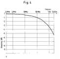
- Fig. 4is a diagram showing the course of the cable attenuation of a 3 m long piece of the coaxial cable used for the coaxial cable arrangement according to the invention on the ordinate (downwards) compared to the frequency of the high-frequency energy on the abscissa in a frequency range from 0.3 MHz to 2 .5 GHz illustrates, with small active or Winding gaps in the shielding device 3 are filled with solder by a wave bath.
- the present inventionis not limited to the treatment of the shielding device 3 with a filling compound described above.
- Such a coaxial cable arrangementhas a third section C, which begins at the proximal end 5 of the antenna arrangement and which is shorter than the first section A of the coaxial cable arrangement, the insulator 2 in the third section C consisting of a first insulation material.
- the insulator 2In the region between the distal end 7 of the third section C and the proximal end 10 of the second section B, the insulator 2 consists of a second insulation material, the first insulation material having a greater mechanical rigidity than the second insulation material. So that there is no undesired reflection of high-frequency energy in the boundary region between the first and the second insulation material, the first insulation material and the second insulation material preferably have a practically identical value for their respective dielectric constant.
- the antenna arrangement according to the inventionis not restricted to use in blood vessels; rather, it is also suitable for applications in other body cavities such as the intestine, vagina, etc.
- a shielding device 3for example made of plastic, can be applied continuously to the shielding device 3 up to the proximal end 10 of the second section B.
- the rigidity of the coaxial cable arrangementcan be changed by applying a sheath made of a covering material in the proximal area which has a greater rigidity than the wrapping material used for the distal region. This procedure has the advantage that no problems arise due to reflected high-frequency energy as a result of approximately different dielectric constants of the insulator 2.
- a coaxial cable arrangement with paired insulating material materials or with paired sheathing materialscan be produced particularly simply and inexpensively if an extrusion device is used which allows a change of the extrusion compound, the first (stiffer) insulation material or the first (stiffer) covering material as the extrusion compound and during the extrusion of the insulation 2 or the insulating jacket 11 in the region of the third section C and of the dielectric jacket 11 in the part of the first section A which does not belong to the third section C, the second (less rigid) insulating material or the second (less rigid) covering material is used as the extrusion compound.
- FIG. 5shows an external view of a dilatation catheter 110 with a coaxial cable arrangement 100 according to the invention inserted therein with an antenna arrangement attached to it.
- a high-frequency generator 114generates high-frequency energy of a frequency of 2.45 GHz, for example, which is fed into the coaxial cable arrangement 100 via a plug connection 4a, 4b and by means of the out the antenna molding 101 and the shielding device 3 formed asymmetrical dipole is emitted.
- the antenna molding 101is arranged in the distal end of the dilatation catheter 110, which is designed as a balloon 111.
- the catheter 110In addition to a first lumen 120, into which the coaxial cable arrangement 100 is inserted up to the point marked by the insertion stop 9, the catheter 110 also has at least two further lumens 121, 122, as shown in FIG. 6 .
- a line 112is introduced into a second lumen 121, by means of which a cooling liquid, for example a saline solution, can be passed through the catheter. By means of this cooling liquid, the parasitic heat generated by parasitic high-frequency radiation of the coaxial cable arrangement 100 can be kept away from the vessel wall and carried away in a harmless manner.
- a guide wire 113is inserted into a third lumen 122. The sterile area of the dilatation catheter shown begins at the proximal end 5 of the coaxial cable arrangement 100 shortly after the plug connection 4 and extends to the outermost distal end of the balloon 111.
- FIG. 6shows a cross section A --- A through the dilatation catheter 110 shown in FIG. 5 with the first lumen 120 for receiving the coaxial cable arrangement 100, with the second lumen 121 for receiving the cooling liquid and with the third lumen 122 for receiving the guide wire 113. If only a small amount of cooling liquid is used, it can be released into the bloodstream through an outlet opening (not shown). In other embodiments of the dilatation catheter 110, a further lumen (not shown) can be provided, through which the cooling solution is returned to the catheter entrance.
Landscapes
- Health & Medical Sciences (AREA)
- Life Sciences & Earth Sciences (AREA)
- Engineering & Computer Science (AREA)
- Biomedical Technology (AREA)
- Surgery (AREA)
- Veterinary Medicine (AREA)
- General Health & Medical Sciences (AREA)
- Heart & Thoracic Surgery (AREA)
- Public Health (AREA)
- Animal Behavior & Ethology (AREA)
- Electromagnetism (AREA)
- Otolaryngology (AREA)
- Molecular Biology (AREA)
- Physics & Mathematics (AREA)
- Medical Informatics (AREA)
- Nuclear Medicine, Radiotherapy & Molecular Imaging (AREA)
- Cardiology (AREA)
- Transplantation (AREA)
- Vascular Medicine (AREA)
- Oral & Maxillofacial Surgery (AREA)
- Media Introduction/Drainage Providing Device (AREA)
- Radiation-Therapy Devices (AREA)
- Electrotherapy Devices (AREA)
- Surgical Instruments (AREA)
Abstract
Translated fromGerman
Description
Translated fromGermanDie Erfindung betrifft eine stabförmige Antennenanordnung mit Zuleitung in Form einer hochfrequenztauglichen Koaxialkabelanordnung, insbesondere zur medizinischen Wärmeapplikation in Körperhohlräumen, wie sie beispielsweise in speziellen Ballonkathetern zur Koronarangioplastie eingesetzt werden kann.The invention relates to a rod-shaped antenna arrangement with a lead in the form of a high-frequency coaxial cable arrangement, in particular for medical heat application in body cavities, as can be used, for example, in special balloon catheters for coronary angioplasty.
Nach einer Beseitigung von Durchblutungsstörungen mittels Aufweiten oder Sprengen von durch Ablagerungen (atheronatös) bedingten Verengungen beispielsweise in Becken-, Bein- oder Koronararterien durch perkutane transluminale Rekanalisierung, im folgenden als "Dilatation" bezeichnet, tritt häufig eine arterielle Dissektion, d.h. eine durch ärztlichen Eingriff (iatrogen) verursachte Verletzung der Arterienwand, auf. Hautlappen, die von der Gefäßwand in das Gefäß hineinhängen, hemmen den Blutfluß und können zum Gefäßverschluß oder sogar - bei Koronararterien - zum Infarkt führen. Zur Vermeidung dieser Komplikation bieten sich zwei Alternativen an: Zum einen können mittels eines Ballonkatheters plazierte Drahtgeflechte ("Stents") implantiert werden, die die Gefäßwand mechanisch stabilisieren und so das Gefäß offenhalten. Dieses Vorgehen weist den Nachteil einer großen Gefahr der Thrombosenbildung auf. Zum anderen ist aus Rosen, A. et al.: "Percutaneous Transluminal Microwave Balloon Angioplasty", Transactions on Microwave Therory and Techniques, Band 38, Nº 1, Januar 1990, ein Verfahren bekannt, bei dem ein mit einem zur Abstrahlung von elektromagnetischen Wellen im Mikrowellenbereich geeigneten asymmetrischen Dipol versehener und in der Regel mehrlumiger Ballonkatheter ("Hot Balloon") eingesetzt wird, der durch ein in ein Lumen eingelegtes Kabel mit Hochfrequenzenergie gespeist wird. Dieser Dilatationskatheter wird in drucklosem Zustand und ohne Zufuhr von Hochfrequenzenergie in das betreffende Gefäß eingeführt und mit Druck beaufschlagt, so daß die gewünschte Aufweitungs- oder Sprengwirkung erzielt wird. Daran anschließend wird dem im Katheter angebrachten Dipol Mikrowellen-Hochfrequenzenergie zugeführt, so daß die Gefäßwand und die übrige unmittelbare Umgebung des Katheterballons kurzzeitig auf eine Temperatur von beispielsweise mehr als 50°C erwärmt werden. Dadurch werden Eiweißsubstanzen zum Gerinnen gebracht, um Hautlappen mit der Gefäßwand zu verkleben.After elimination of circulatory disorders by widening or blasting of constrictions caused by deposits (atheronatous), for example in pelvic, leg or coronary arteries, by means of percutaneous transluminal recanalization, hereinafter referred to as "dilatation", arterial dissection, that is to say by medical intervention, often occurs (iatrogenic) caused injury to the arterial wall. Skin flaps that hang from the wall of the vessel into the vessel inhibit blood flow and can lead to vascular occlusion or even - in the case of coronary arteries - to a heart attack. There are two alternatives to avoid this complication: First, wire meshes ("stents") can be implanted using a balloon catheter, which mechanically stabilize the vessel wall and thus keep the vessel open. This procedure has the disadvantage of a great risk of thrombosis formation. On the other hand, a method is known from Rosen, A. et al .: "Percutaneous Transluminal Microwave Balloon Angioplasty", Transactions on Microwave Therory and Techniques,
Durch die in einen Dilatationskatheter eingesetzte Koaxialkabelanordnung muß einerseits die zur Gewebeerwärmung dienende Mikrowellen-Hochfrequenzenergie bei möglichst geringen Verlusten zum Antennendipol im Ballon geleitet werden. Weist das verwendete Koaxialkabel eine zu hohe Dämpfung auf, so ist dies zwangsläufig mit einer unerwünschten Wärmeerzeugung in dem Lumen des Katheters verbunden, in den die Koaxialkabelanordnung eingesetzt ist. Diese unerwünschte Wärmeerzeugung kann beispielsweise zu einer gefährlichen Koagulation des den Katheterschlauch umgebenden Blutes führen. Andererseits muß die Kabelanordnung im distalen Bereich mit geringen Kräften leicht biegbar sein, damit sie insbesondere im Koronarbereich auch durch enge Biegungen hindurch in das betreffende Gefäß eingeführt werden kann, während im proximalen Bereich eine Mindeststeifigkeit der Kabelanordnung erforderlich ist, um sie in enge Lumen eines Katheters einführen und sodann darin vorschieben zu können. Darüber hinaus sollte die Kabelanordnung einen Durchmesser aufweisen, der so gering wie möglich ist, damit der Lumen ebenfalls mit geringem Querschnitt ausgeführt werden kann.Due to the coaxial cable arrangement inserted into a dilatation catheter, the microwave high-frequency energy used to heat the tissue must be conducted to the antenna dipole in the balloon with the lowest possible losses. If the coaxial cable used has too high an attenuation, this is inevitably associated with an undesirable generation of heat in the lumen of the catheter in which the coaxial cable arrangement is inserted. This undesired generation of heat can lead, for example, to dangerous coagulation of the blood surrounding the catheter tube. On the other hand, the cable arrangement in the distal region must be easily bendable with low forces, so that it can also be introduced into the vessel in question through narrow bends, in particular in the coronary region, while a minimum rigidity of the cable arrangement is required in the proximal region in order to insert it into narrow lumens of a catheter to be able to introduce and then advance. In addition, the cable arrangement should be one Have a diameter that is as small as possible so that the lumen can also be designed with a small cross-section.
Daher werden in Dilatationskathetern bislang Koaxialkabel eingesetzt, die als Schirm beispielsweise einen gewickelten oder geflochtenen Flachbandleiter oder Rundleiter aufweisen, der im proximalen Bereich mit einem dünnen Metallröhrchen überzogen ist, um dort die Steifigkeit zu erhöhen. Dieser Aufbau weist jedoch den Nachteil auf, daß ein Metallröhrchen, das auf ein Kabel aufgeschoben werden soll, infolge der dafür benötigten Festigkeit eine verhältnismäßig große Wandstärke aufweisen muß und führt somit zu einem unerwünschten Anwachsen des effektiven Kabeldurchmessers. Dadurch verringert sich der im Lumen zur Verfügung stehende Spielraum zum Verschieben des Kabels; unter Umständen kann die Wahl eines Katheterschlauches mit größerem Durchmesser erforderlich werden. Auch ist die Fertigung einer derartigen Kabelanordnung aufwendig und unter wirtschaftlichen Gesichtspunkten nachteilig, da das aufgeschobene Metallröhrchen in einem gesonderten Fertigungsschritt auf geeignete Weise mit dem Koaxialkabel verbunden werden muß.For this reason, coaxial cables have hitherto been used in dilatation catheters which, for example, have a wound or braided ribbon conductor or round conductor, which is covered with a thin metal tube in the proximal region in order to increase the rigidity there. However, this structure has the disadvantage that a metal tube that is to be pushed onto a cable must have a relatively large wall thickness due to the strength required for it, and thus leads to an undesirable increase in the effective cable diameter. This reduces the scope available in the lumen for moving the cable; it may be necessary to select a catheter tube with a larger diameter. The manufacture of such a cable arrangement is also complex and disadvantageous from an economic point of view, since the pushed-on metal tube has to be connected to the coaxial cable in a suitable manufacturing step.
Ein anderer Ansatz, der für Kabelanordnungen in Dilatationskathetern verwendet wird, besteht darin, zwei Kabelsektionen unterschiedlicher Steifigkeit getrennt zu fertigen und an einer gemeinsamen Schnittstelle mit einer Mikrosteckverbindung elektrisch und mechanisch miteinander zu verbinden. Abgesehen von der Verschlechterung der elektrischen Übertragungseigenschaften der Kabelanordnung durch die zusätzliche durch die Schnittstelle bedingte Dämpfung und dem hohen konstruktiven und fertigungstechnischen Aufwand hierfür muß dieser Ansatz auch deswegen als nachteilig angesehen werden, weil für den Patienten das zusätzliche Risiko eines fehlerhaften Öffnens der Verbindung während eines Eingriffes besteht.Another approach that is used for cable arrangements in dilatation catheters is to manufacture two cable sections of different stiffness separately and to connect them electrically and mechanically at a common interface with a micro connector. Apart from the deterioration in the electrical transmission properties of the cable arrangement due to the additional attenuation caused by the interface and the high constructional and manufacturing expenditure for this, this approach must be taken can also be considered disadvantageous because there is an additional risk for the patient of incorrectly opening the connection during an operation.
Aufgabe der Erfindung ist es daher, eine verbesserte Antennenanordnung mit Zuleitung in Form einer hochfrequenztauglichen Koaxialkabelanordnung insbesondere zur medizinischen Wärmeapplikation in Körperhohlräumen nach dem Oberbegriff der Ansprüche 1, 4 oder 5 verfügbar zu machen, die einfach und wirtschaftlich zu fertigen ist, die hervorragende elektrische Übertragungseigenschaften sowie einen geringen Durchmesser aufweist und die bei der Anwendung einfach, schnell und sicher gehandhabt werden kann.It is therefore an object of the invention to provide an improved antenna arrangement with a feed line in the form of a high-frequency coaxial cable arrangement, in particular for medical heat application in body cavities, which is simple and economical to manufacture, and which has excellent electrical transmission properties and has a small diameter and can be handled easily, quickly and safely during use.
Diese Aufgabe wird durch die im Kennzeichenteil der Ansprüche 1, 4 bzw. 5 angegebenen Merkmale gelöst. In den Unteransprüchen 2-3 sowie 7-10 sind vorteilhafte Weiterentwicklungen der Gegenstände derjenigen Ansprüche, auf die sie jeweils rückbezogen sind, angegeben. Dem Anspruch 6 ist ein Verfahren zur Herstellung einer erfindungsgemäßen Koaxialkabelanordnung nach Anspruch 4 oder 5 zu entnehmen. Der Anspruch 11 beinhaltet eine Kombination der erfindungsgemäßen Koaxialkabelanordnung mit einem dafür geeigneten Dilatationskatheter. Die Ansprüche 12 und 13 beschreiben schließlich ein Verfahren zur Anwendung der erfindungsgemäßen Koaxialkabelanordnung in Zusammenwirken mit einem Dilatationskatheter.This object is achieved by the features specified in the characterizing part of
Dadurch, daß beispielsweise inhärente Wirk,-Flecht- oder Wickellücken im Schirm der erfindungsgemäßen Koaxialkabelanordnung mit Lötzinn oder elektrisch leitfähigem Kunststoff verfüllt werden, wird in einem proximal zum Anwender gelegenen Kabelbereich sowohl eine beim Einführen der Anordnung in einen Dilatationskatheter vorteilhafte größere mechanische Steifigkeit als auch eine Verminderung unerwünschter parasitärer Hochfrequenzabstrahlung im proximalen Kabelbereich erreicht.Because, for example, inherent active, braid or winding gaps in the shield of the coaxial cable arrangement according to the invention are filled with solder or electrically conductive plastic, In a cable area located proximal to the user, both greater mechanical stiffness, which is advantageous when inserting the arrangement into a dilatation catheter, and a reduction in undesired parasitic high-frequency radiation in the proximal cable area are achieved.
Die Versteifung eines proximalen Kabelbereiches kann auch dadurch erzielt werden, daß der um den Innenleiter angeordnete Isolator bzw. der den Schirm umgebende Mantel im proximalen Bereich aus einem steiferen Kunststoff hergestellt wird. In einem distalen Bereich weist der Isolator bzw. Mantel eine demgegenüber geringere Steifigkeit auf, damit die Anordnung beispielsweise durch enge Koronararterien leicht und ohne Verletzungsgefahr geschoben werden kann. Die Herstellung einer solchen Ausführungsform der erfindungsgemäßen Antennenanordnung kann besonders vorteilhaft durch einen Extrudierprozeß erfolgen, bei dem die Extrudiermasse umgeschaltet wird.The stiffening of a proximal cable area can also be achieved in that the insulator arranged around the inner conductor or the sheath surrounding the shield is made in the proximal area from a more rigid plastic. In contrast, the insulator or sheath has a lower rigidity in a distal area, so that the arrangement can be pushed easily and without risk of injury, for example through narrow coronary arteries. Such an embodiment of the antenna arrangement according to the invention can be produced particularly advantageously by an extrusion process in which the extrusion compound is switched over.
Bei einer Dilatationsbehandlung mit einem Dilatationskatheter erweist es sich als vorteilhaft, einen separaten Lumen vorzusehen, durch den eine Kühlflüssigkeit hindurchgeleitet wird, um parasitäre Wärme, die durch parasitäre Hochfrequenzabstrahlung der Koaxialkabelanordnung im proximalen Bereich anfällt, abführen zu können.In the case of dilatation treatment with a dilatation catheter, it proves to be advantageous to provide a separate lumen through which a cooling liquid is passed in order to be able to dissipate parasitic heat which arises in the proximal region due to parasitic high-frequency radiation from the coaxial cable arrangement.
Anhand der Zeichnung werden im folgenden mehrere Ausführungsbeispiele der Erfindung erläutert und deren Vorteile dargestellt. Es zeigen:
- Fig. 1:
- einen Querschnitt durch ein Ausführungsbeispiel einer erfindungsgemäßen Antennenanordnung.
- Fig. 2:
- einen Querschnitt durch ein weiteres Ausführungsbeispiel einer erfindungsgemäßen Antennenanordnung mit einem Antennenformkörper.
- Fig. 3:
- ein Diagramm, das den Verlauf der Kabeldämpfung einer herkömmlichen Koaxialkabelanordnung gegenüber der Frequenz der Hochfrequenzenergie veranschaulicht.
- Fig. 4:
- ein Diagramm, das den Verlauf der Kabeldämpfung einer erfindungsgemäßen Koaxialkabelanordnung gegenüber der Frequenz der Hochfrequenzenergie veranschaulicht.
- Fig. 5:
- eine Außenansicht eines Dilatationskatheters mit einer erfindungsgemäßen Antennenanordnung.
- Fig. 6:
- einen Querschnitt A---A durch den inFig. 5 dargestellten Dilatationskatheter.
- Fig. 1:
- a cross section through an embodiment of an antenna arrangement according to the invention.
- Fig. 2:
- a cross section through a further embodiment of an antenna arrangement according to the invention with a shaped antenna body.
- Fig. 3:
- a diagram illustrating the course of the cable loss of a conventional coaxial cable arrangement versus the frequency of the radio frequency energy.
- Fig. 4:
- a diagram illustrating the course of the cable loss of a coaxial cable arrangement according to the invention compared to the frequency of the radio frequency energy.
- Fig. 5:
- an external view of a dilatation catheter with an antenna arrangement according to the invention.
- Fig. 6:
- a cross section A --- A through the dilatation catheter shown inFig. 5 .
InFig. 1 werden die Grundideeen der erfindungsgemäßen Antennenanordnung an einem Ausführungsbeispiel veranschaulicht. Ein durchgehender Innenleiter 1 verläuft von einem proximalen Ende 5, das beispielsweise in Gestalt einer Steckverbindung 4 ausgeführt sein kann, die geeignet ist, die Koaxialkabelanordnung mit einem im Mikrowellenbereich arbeitenden Hochfrequenzgenerator (nicht dargestellt) lösbar zu verbinden, bis zu einem distalen Ende 6. In einem ersten Abschnitt A der Koaxialkabelanordnung, der am proximalen Ende 5 beginnt und vorteilhaft eine Länge von einigen Dezimetern bis zu mehr als einem Meter aufweist, weist die Koaxialkabelanordnung einen zylindrisch um den durchgehenden Innenleiter 1 angeordneten Isolator 2 sowie eine auf den Isolator 2 aufgebrachte zusammenhängende Abschirmeinrichtung 3 auf, die beispielsweise aus dünnem Metalldraht oder aus dünnem metallischen Flachbandleitern gewirkt, geflochten oder gewickelt ist. In einem zweiten Abschnitt B liegt der Innenleiter frei und kann im Zusammenwirken mit der Abschirmeinrichtung 3 als asymmetrischer Stabdipol die Funktion einer Sendeantenne 8 für Hochfrequenzenergie im Mikrowellenbereich erfüllen. Die Länge des zweiten Abschnittes B beträgt beispielsweise einige Zentimeter. Um der Koaxialkabelanordnung im proximalen Bereich eine Mindeststeifigkeit zu verleihen die für das Einführen und Vorschieben der Koaxialkabelanordnung in einem Führungslumen eines Dilatationskatheters erforderlich ist, ist ein dritter Abschnitt C der Koaxialkabelanordnung festgelegt, der am proximalen Ende 5 beginnt und auf jeden Fall kürzer als der erste Abschnitt A ist.1 illustrates the basic ideas of the antenna arrangement according to the invention using an exemplary embodiment. A continuous
Dieser dritte Abschnitt C der erfindungsgemäßen Koaxialkabelanordnung ist beispielsweise durch eine Schwallbadbehandlung so behandelt worden, daß kleine, der gewirkten bzw. gewickelten Abschirmeinrichtung 3 inhärente Lücken durch eine versteifende leitfähige Masse, in diesem Beispiel Lötzinn, verfüllt sind. Die Erfindung ist jedoch nicht auf die Verwendung von Lötzinn als Verfüllmasse beschränkt, vielmehr sind alle Verfüllmassen verwendbar, die genügend elektrische Leitfähigkeit und genügende Versteifungswirkung aufweisen. Beispielsweise sind auch elektrisch leitfähige Kunststoffe geeignet.This third section C of the coaxial cable arrangement according to the invention has been treated, for example, by a wave bath treatment in such a way that small gaps inherent in the knitted or
Für Anwendungen, bei denen eine höhere Flexibilität am distalen Ende der Koaxialkabelanordnung nicht benötigt wird, weil keine Körperhohlräume mit engen Biegungen durchlaufen werden, und bei denen es nur auf die Hochfrequenzeigenschaften ankommt, kann es vorteilhaft sein, den gesamten Abschnitt A mit Verfüllmasse zu versehen.For applications in which a higher flexibility at the distal end of the coaxial cable arrangement is not required because no body cavities with narrow bends are passed through and in which only the high-frequency properties are important, it can be advantageous to provide the entire section A with filler compound.
Der Abschnitt zwischen dem distalen Ende 7 des dritten Abschnittes C und dem proximalen Ende 10 des zweiten Abschnittes B wird nicht versteift, damit die Koaxialkabelanordnung in einem Dilatationskatheter beispielsweise in die Koronararterien an engen Biegungen und dergleichen leicht und ohne Verletzungsgefahr eingeführt werden kann.The section between the
Bei einer bevorzugten Ausführungsform weist die erfindungsgemäße Koaxialkabelanordnung im Bereich des proximalen Endes 5 einen Einführungsanschlag 9 auf, der in einer vorbestimmten Entfernung D zum distalen Ende 6 angebracht ist, um dem Anwender anzuzeigen, wie weit die Koaxialkabelanordnung in einen Katheter (nicht dargestellt) eingeführt werden darf, und um ein weitergehendes Einführen zu verhindern. Der Bereich der Koaxialkabelanordnung vom proximalen Ende 5 bis zum Einführungsanschlag 9 wird vorteilhaft mit einem isolierenden äußeren Mantel 11 umhüllt. Der Anschlag kann auch durch die Stirnfläche des an der Stelle des Anschlages aufhörenden Mantels 11 gebildet sein.In a preferred embodiment, the coaxial cable arrangement according to the invention has an
Fig 2 zeigt ein weiteres Ausführungsbeispiel einer erfindungsgemäßen Antennenanordnung mit einem metallischen, elektrisch leitfähigen Antennenformkörper 101, der zur Verbesserung der Hochfrequenzeigenschaften am zweiten Abschnitt B der Koaxialkabelanordnung angebracht ist. Bevorzugt wird eine Kegelform, wobei die stumpfe Basis des Kegels das äußerste distale Ende 6 der Koaxialkabelanordnung bildet. Durch den Antennenformkörper 101 wird eine günstigere Anpassung des Wellenwiderstandes der Koaxialkabelanordnung an den Wellenwiderstand des im Bereich des Katheterballons liegenden Gewebes erreicht. Hinsichtlich der übrigen Gestaltungsmerkmale entspricht dieses Ausführungsbeispiel demjenigen Ausführungsbeispiel, das vorstehend mit Bezug aufFig. 1 erläutert ist. Gleiche Bestandteile sind mit gleichen Bezugszeichen gekennzeichnet.2 shows a further exemplary embodiment of an antenna arrangement according to the invention with a metallic, electrically conductive
Fig. 3 ist ein Diagramm, das den Verlauf der Kabeldämpfung eines 3 m langen nicht erfindungsgemäßen Vergleichs-Koaxialkabels auf der Ordinate (nach unten abgetragen) gegenüber der Frequenz der Hochfrequenzenergie auf der Abszisse in einem Frequenzbereich von 0,3 MHz bis 2,5 GHz veranschaulicht, wobei das Vergleichs-Koaxialkabel dem für die erfindungsgemäße Koaxialkabelanordnung verwendeten gleicht, außer daß inhärente Wirk-, Flecht- bzw. Wickellücken in der Abschirmeinrichtung 3 nicht durch eine leitfähige Verfüllmasse verfüllt sind.Fig. 3 is a graph showing the course of the cable loss of a 3 m long comparison coaxial cable according to the invention on the ordinate (downwards) versus the frequency of the radio frequency energy on the abscissa in a frequency range from 0.3 MHz to 2.5 GHz illustrates, wherein the comparison coaxial cable is the same as that used for the coaxial cable arrangement according to the invention, except that inherent active, braiding or winding gaps in the
Fig. 4 ist ein Diagramm, das den Verlauf der Kabeldämpfung eines 3 m langen Stückes des für die erfindungsgemäße Koaxialkabelanordnung verwendeten Koaxialkabels auf der Ordinate (nach unten abgetragen) gegenüber der Frequenz der Hochfrequenzenergie auf der Abszisse in einem Frequenzbereich von 0,3 MHz bis 2,5 GHz veranschaulicht, wobei kleine Wirk- bzw. Wickellücken in der Abschirmeinrichtung 3 durch ein Schwallbad mit Lötzinn verfüllt sind.Fig. 4 is a diagram showing the course of the cable attenuation of a 3 m long piece of the coaxial cable used for the coaxial cable arrangement according to the invention on the ordinate (downwards) compared to the frequency of the high-frequency energy on the abscissa in a frequency range from 0.3 MHz to 2 .5 GHz illustrates, with small active or Winding gaps in the
Durch Vergleich derFig. 3 mit derFig. 4 wird ersichtlich, daß die Kabeldämpfung bei dem für die erfindungsgemäße Koaxialkabelanordnung verwendeten Koaxialkabel in wesentlich geringerem Maße ansteigt als bei dem Vergleichskabel inFig. 3. Wie aus den Figuren ersichtlich, beträgt die Kabeldämpfung bei einer Frequenz von 2,45 GHz beim Vergleichskabel ca. -2,7 dB/m, während bei der erfindungsgemäßen Lösung ca. -1,83 dB/m erzielt werden. Dies bedeutet, daß die parasitäre Abstrahlung von Hochfrequenzenergie außerhalb des eigentlichen Antennenbereiches 8, 101 durch das Verfüllen der kleinen Lücken vermindert ist, so daß daher auch die durch die parasitär abgestrahlte Hochfrequenzenergie in den Blutgefäßen, durch die der Katheter geführt werden muß, um an den Ort der Dilatationsbehandlung zu gelangen, freigesetzte parasitäre Wärme vermindert wird. Diese Eigenschaft stellt einen signifikanten Vorteil gegenüber dem Stand der Technik dar, der beispielsweise zu einer Verkürzung der Dilatationsbehandlung genutzt werden kann, indem die Leistung der in die Koaxialkabelanordnung eingespeisten Hochfrequenzenergie erhöht wird. Trotz dieser erhöhten Energieeinspeisung ist somit keine Schädigung der Blutgefäße, durch die der Katheter hindurchgeführt wird, zu befürchten.By comparingFIG. 3 withFIG. 4 , it can be seen that the cable attenuation in the coaxial cable used for the coaxial cable arrangement according to the invention increases to a much lesser extent than in the comparison cable inFIG. 3. As can be seen from the figures, the cable attenuation in one Frequency of 2.45 GHz for the comparison cable approx. -2.7 dB / m, while approx. -1.83 dB / m can be achieved with the solution according to the invention. This means that the parasitic radiation of radio frequency energy outside the
Die vorliegende Erfindung ist nicht auf die vorstehend beschriebene Behandlung der Abschirmeinrichtung 3 mit einer Verfüllmasse beschränkt.The present invention is not limited to the treatment of the
Die geforderten mechanischen Eigenschaften der Koaxialkabelanordnung, nämlich eine höhere Steifigkeit im proximalen Bereich und eine demgegenüber geringere Steifigkeit im distalen Bereich, sind auch dann gegeben, wenn für den Isolator 2 in den entsprechenden Bereichen jeweils unterschiedliche Isoliermaterialien mit unterschliedlichen Steifigkeitseigenschaften eingesetzt werden. Eine derartige Koaxialkabelanordnung weist einen dritten Abschnitt C auf, der am proximalen Ende 5 der Antennenanordnung beginnt und der kürzer ist als der erste Abschnitt A der Koaxialkabelanordnung, wobei in dem dritten Abschnitt C der Isolator 2 aus einem ersten Isolationsmaterial besteht. Der Isolator 2 besteht im Bereich zwischen dem distalen Ende 7 des dritten Abschnittes C und dem proximalen Ende 10 des zweiten Abschnittes B aus einem zweiten Isolationsmaterial, wobei das erste Isolationsmaterial eine größere mechanische Steifigkeit als das zweite Isolationsmaterial aufweist. Damit im Grenzbereich zwischen dem ersten und dem zweiten Isolationsmaterial keine unerwünschte Reflexion von Hochfrequenzenergie erfolgt, weisen das erste Isolationsmaterial und das zweite Isolationsmaterial vorzugsweise einen praktisch gleichen Wert für ihre jeweilige Dielektrizitätskonstante auf.The required mechanical properties of the coaxial cable arrangement, namely a higher stiffness in the proximal area and a contrast Lower rigidity in the distal area is also given if different insulating materials with different rigidity properties are used for the
Die erfindungsgemäße Antennenanordnung ist nicht auf eine Anwendung in Blutgefäßen beschränkt; vielmehr ist sie auch für Anwendungen in anderen Körperhohlräumen wie Darm, Vagina etc. geeignet. Insbesondere in solchen Körperhohlräumen, die das Einführen eines Katheters größeren Durchmessers erlauben, kann auf die Abschirmeinrichtung 3 durchgehend bis zum proximalen Ende 10 des zweiten Abschnittes B ein dielektrischer Mantel beispielsweise aus Kunststoff aufgebracht werden. In diesem Fall kann die Steifigkeit der Koaxialkabelanordnung dadurch verändert werden, daß im proximalen Bereich ein Mantel aus einem Umhüllungsmaterial aufgebracht wird, das eine größere Steifigkeit als das Umhüllungsmaterial aufweist, das für den distalen Bereich verwendet wird. Diese Vorgehensweise hat den Vorteil, daß keine Probleme durch reflektierte Hochfrequenzenergie infolge etwa unterschiedlicher Dielektrizitätskonstanten des Isolators 2 entstehen.The antenna arrangement according to the invention is not restricted to use in blood vessels; rather, it is also suitable for applications in other body cavities such as the intestine, vagina, etc. In particular in such body cavities that allow the insertion of a catheter of larger diameter, a
Da sowohl die Kabelisolation als auch der Mantel zweckmäßig durch Extrudieren auf den durchgehenden Innenleiter 1 bzw. auf die Abschirmeinrichtung 3 aufgebracht werden, kann eine Koaxialkabelanordnung mit gepaarten Isolierstoffmaterialien bzw. mit gepaarten Umhüllungsmaterialien besonders einfach und kostengünstig hergestellt werden, wenn eine Extrudiervorrichtung verwendet wird, die einen Wechsel der Extrudiermasse ermöglicht, wobei während des Extrudierens der Isolation 2 bzw. des isolierenden Mantels 11 im Bereich des dritten Abschnittes C das erste (steifere) Isoliermaterial bzw. das erste (steifere) Umhüllungsmaterial als Extrudiermasse und während des Extrudierens der Isolation 2 bzw. des dielektrischen Mantels 11 in dem Teil des ersten Abschnittes A, der nicht zum dritten Abschnitt C gehört, das zweite (weniger steife) Isoliermaterial bzw. das zweite (weniger steife) Umhüllungsmaterial als Extrudiermasse eingesetzt wird.Since both the cable insulation and the jacket are expediently applied to the continuous
Fig. 5 stellt eine Außenansicht eines Dilatationskatheters 110 mit einer darin eingesetzten erfindungsgemäßen Koaxialkabelanordnung 100 mit daran angebrachter Antennenanordnung dar. Ein Hochfrequenzgenerator 114 erzeugt Hochfrequenzenergie einer Frequenz von beispielsweise 2,45 GHz, die über eine Steckverbindung 4a, 4b in die Koaxialkabelanordnung 100 eingespeist und mittels des aus dem Antennenformstück 101 und der Abschirmeinrichtung 3 gebildeten asymmetrischen Dipols abgestrahlt wird. Das Antennenformstück 101 ist im distalen Ende des Dilatationskatheters 110 angeordnet, das als Ballon 111 ausgebildet ist. Neben einem ersten Lumen 120, in das die Koaxialkabelanordnung 100 bis zu dem durch den Einführanschlag 9 markierten Punkt eingeführt ist, weist der Katheter 110 noch mindestens zwei weitere Lumen 121,122 auf, wie inFig. 6 gezeigt ist. In einen zweiten Lumen 121 ist eine Leitung 112 eingeführt, mittels derer eine Kühlflüssigkeit, beispielsweise eine Salzlösung, durch den Katheter hindurchgeleitet werden kann. Durch diese Kühlflüssigkeit kann die durch parasitäre Hochfrequenzstrahlung der Koaxialkabelanordnung 100 entstehende parasitäre Wärme von der Gefäßwand abgehalten und in unbedenklicher Weise weggeführt werden. In einen dritten Lumen 122 ist ein Führungsdraht 113 eingeführt. Der sterile Bereich des gezeigten Dilatationskatheters beginnt am proximalen Ende 5 der Koaxialkabelanordnung 100 kurz nach der Steckverbindung 4 und erstreckt sich bis zum äußersten distalen Ende des Ballons 111.5 shows an external view of a
Fig. 6 zeigt einen Querschnitt A---A durch den inFig. 5 dargestellten Dilatationskatheter 110 mit dem ersten Lumen 120 zur Aufnahme der Koaxialkabelanordnung 100, mit dem zweiten Lumen 121 zur Aufnahme der Kühlflüssigkeit und mit dem dritten Lumen 122 zur Aufnahme des Führungsdrahtes 113. Wird nur eine geringe Menge Kühlflüssigkeit eingesetzt, so kann sie durch eine Austrittsöffnung (nicht dargestellt) in den Blutkreislauf abgegeben werden. In anderen Ausführungsformen des Dilatationskatheters 110 kann ein weiteres Lumen (nicht dargestellt) vorgesehen sein, durch das die Kühllösung zum Kathetereingang zurückgeführt wird.FIG. 6 shows a cross section A --- A through the
Claims (13)
Translated fromGermandadurch gekennzeichnet,

characterized,
dadurch gekennzeichnet,
daß in dem Lumen eine Antennenanordnung gemäß einem der Ansprüche 1-5 oder 7-10 angeordnet ist.Dilatation catheter with at least one lumen,
characterized,
that an antenna arrangement according to one of claims 1-5 or 7-10 is arranged in the lumen.
dadurch gekennzeichnet,
daß in eines der Lumen eine Antennenanordnung gemäß einem der Ansprüche 1-5 oder 7-10 einführbar ist und daß ein zweites der Lumen an eine Kühlflüssigkeitsquelle anschließbar ist.Dilatation device with a multi-lumen dilatation catheter,
characterized,
that an antenna arrangement according to one of claims 1-5 or 7-10 can be inserted into one of the lumens and that a second one of the lumens can be connected to a coolant source.
Applications Claiming Priority (2)
| Application Number | Priority Date | Filing Date | Title |
|---|---|---|---|
| DE4122050ADE4122050C2 (en) | 1991-07-03 | 1991-07-03 | Antenna arrangement with supply line for medical heat application in body cavities |
| DE4122050 | 1991-07-03 |
Publications (2)
| Publication Number | Publication Date |
|---|---|
| EP0521264A2true EP0521264A2 (en) | 1993-01-07 |
| EP0521264A3 EP0521264A3 (en) | 1993-06-16 |
Family
ID=6435365
Family Applications (1)
| Application Number | Title | Priority Date | Filing Date |
|---|---|---|---|
| EP19920107898WithdrawnEP0521264A3 (en) | 1991-07-03 | 1992-05-11 | Antenna device with feed |
Country Status (4)
| Country | Link |
|---|---|
| US (1) | US5344441A (en) |
| EP (1) | EP0521264A3 (en) |
| JP (1) | JPH05245208A (en) |
| DE (1) | DE4122050C2 (en) |
Cited By (169)
| Publication number | Priority date | Publication date | Assignee | Title |
|---|---|---|---|---|
| DE4305663A1 (en)* | 1992-08-12 | 1994-02-17 | Vidamed Inc | Medical probe device and method |
| WO1995005869A1 (en)* | 1993-08-24 | 1995-03-02 | Kaare Grue | A probe for a microwave apparatus for clinical and surgical treatment |
| EP1723922A1 (en)* | 2005-05-10 | 2006-11-22 | Vivant Medical, Inc. | Reinforced high strength microwave antenna |
| US7642451B2 (en) | 2008-01-23 | 2010-01-05 | Vivant Medical, Inc. | Thermally tuned coaxial cable for microwave antennas |
| US7713076B2 (en) | 2007-11-27 | 2010-05-11 | Vivant Medical, Inc. | Floating connector for microwave surgical device |
| US7863984B1 (en) | 2009-07-17 | 2011-01-04 | Vivant Medical, Inc. | High efficiency microwave amplifier |
| US7862559B2 (en) | 2001-11-02 | 2011-01-04 | Vivant Medical, Inc. | High-strength microwave antenna assemblies and methods of use |
| US8069553B2 (en) | 2009-09-09 | 2011-12-06 | Vivant Medical, Inc. | Method for constructing a dipole antenna |
| US8118808B2 (en) | 2009-03-10 | 2012-02-21 | Vivant Medical, Inc. | Cooled dielectrically buffered microwave dipole antenna |
| US8131339B2 (en) | 2007-11-27 | 2012-03-06 | Vivant Medical, Inc. | System and method for field ablation prediction |
| US8192427B2 (en) | 2008-06-09 | 2012-06-05 | Tyco Healthcare Group Lp | Surface ablation process with electrode cooling methods |
| US8197473B2 (en) | 2009-02-20 | 2012-06-12 | Vivant Medical, Inc. | Leaky-wave antennas for medical applications |
| US8202270B2 (en) | 2009-02-20 | 2012-06-19 | Vivant Medical, Inc. | Leaky-wave antennas for medical applications |
| US8211098B2 (en) | 2008-08-25 | 2012-07-03 | Vivant Medical, Inc. | Microwave antenna assembly having a dielectric body portion with radial partitions of dielectric material |
| US8216227B2 (en) | 2009-05-06 | 2012-07-10 | Vivant Medical, Inc. | Power-stage antenna integrated system with junction member |
| US8235981B2 (en) | 2009-06-02 | 2012-08-07 | Vivant Medical, Inc. | Electrosurgical devices with directional radiation pattern |
| US8246615B2 (en) | 2009-05-19 | 2012-08-21 | Vivant Medical, Inc. | Tissue impedance measurement using a secondary frequency |
| US8246614B2 (en) | 2008-04-17 | 2012-08-21 | Vivant Medical, Inc. | High-strength microwave antenna coupling |
| US8282632B2 (en) | 2009-09-28 | 2012-10-09 | Vivant Medical, Inc. | Feedpoint optimization for microwave ablation dipole antenna with integrated tip |
| US8292881B2 (en) | 2009-05-27 | 2012-10-23 | Vivant Medical, Inc. | Narrow gauge high strength choked wet tip microwave ablation antenna |
| US8313486B2 (en) | 2010-01-29 | 2012-11-20 | Vivant Medical, Inc. | System and method for performing an electrosurgical procedure using an ablation device with an integrated imaging device |
| US8317703B2 (en) | 2011-02-17 | 2012-11-27 | Vivant Medical, Inc. | Energy-delivery device including ultrasound transducer array and phased antenna array, and methods of adjusting an ablation field radiating into tissue using same |
| US8328799B2 (en) | 2009-08-05 | 2012-12-11 | Vivant Medical, Inc. | Electrosurgical devices having dielectric loaded coaxial aperture with distally positioned resonant structure |
| US8328800B2 (en) | 2009-08-05 | 2012-12-11 | Vivant Medical, Inc. | Directive window ablation antenna with dielectric loading |
| US8328801B2 (en) | 2009-08-17 | 2012-12-11 | Vivant Medical, Inc. | Surface ablation antenna with dielectric loading |
| US8334812B2 (en) | 2009-06-19 | 2012-12-18 | Vivant Medical, Inc. | Microwave ablation antenna radiation detector |
| US8343149B2 (en) | 2008-06-26 | 2013-01-01 | Vivant Medical, Inc. | Deployable microwave antenna for treating tissue |
| USD673685S1 (en) | 2010-09-08 | 2013-01-01 | Vivant Medical, Inc. | Microwave device spacer and positioner with arcuate slot |
| US8353901B2 (en) | 2007-05-22 | 2013-01-15 | Vivant Medical, Inc. | Energy delivery conduits for use with electrosurgical devices |
| US8355803B2 (en) | 2009-09-16 | 2013-01-15 | Vivant Medical, Inc. | Perfused core dielectrically loaded dipole microwave antenna probe |
| US8353902B2 (en) | 2008-01-31 | 2013-01-15 | Vivant Medical, Inc. | Articulating ablation device and method |
| US8353903B2 (en) | 2009-05-06 | 2013-01-15 | Vivant Medical, Inc. | Power-stage antenna integrated system |
| US8376948B2 (en) | 2011-02-17 | 2013-02-19 | Vivant Medical, Inc. | Energy-delivery device including ultrasound transducer array and phased antenna array |
| US8394092B2 (en) | 2009-11-17 | 2013-03-12 | Vivant Medical, Inc. | Electromagnetic energy delivery devices including an energy applicator array and electrosurgical systems including same |
| US8394087B2 (en) | 2009-09-24 | 2013-03-12 | Vivant Medical, Inc. | Optical detection of interrupted fluid flow to ablation probe |
| US8394086B2 (en) | 2008-09-03 | 2013-03-12 | Vivant Medical, Inc. | Microwave shielding apparatus |
| US8409187B2 (en) | 2009-09-08 | 2013-04-02 | Covidien Lp | Microwave antenna probe with high-strength ceramic coupler |
| US8414554B2 (en) | 2008-05-14 | 2013-04-09 | J & J Solutions, Inc. | Systems and methods for safe medicament transport |
| USD680220S1 (en) | 2012-01-12 | 2013-04-16 | Coviden IP | Slider handle for laparoscopic device |
| US8430871B2 (en) | 2009-10-28 | 2013-04-30 | Covidien Lp | System and method for monitoring ablation size |
| US8463396B2 (en) | 2009-05-06 | 2013-06-11 | Covidien LLP | Power-stage antenna integrated system with high-strength shaft |
| US8469953B2 (en) | 2009-11-16 | 2013-06-25 | Covidien Lp | Twin sealing chamber hub |
| US8491579B2 (en) | 2010-02-05 | 2013-07-23 | Covidien Lp | Electrosurgical devices with choke shorted to biological tissue |
| US8512328B2 (en) | 2008-10-13 | 2013-08-20 | Covidien Lp | Antenna assemblies for medical applications |
| US8523854B2 (en) | 2008-08-28 | 2013-09-03 | Covidien Lp | Microwave antenna |
| US8535340B2 (en) | 2009-10-21 | 2013-09-17 | Covidien Lp | Methods for ultrasonic tissue sensing and feedback |
| US8545493B2 (en) | 2009-09-29 | 2013-10-01 | Covidien Lp | Flow rate monitor for fluid cooled microwave ablation probe |
| US8552915B2 (en) | 2009-06-19 | 2013-10-08 | Covidien Lp | Microwave ablation antenna radiation detector |
| US8556889B2 (en) | 2009-09-29 | 2013-10-15 | Covidien Lp | Flow rate monitor for fluid cooled microwave ablation probe |
| US8617153B2 (en) | 2010-02-26 | 2013-12-31 | Covidien Lp | Tunable microwave ablation probe |
| US8651146B2 (en) | 2007-09-28 | 2014-02-18 | Covidien Lp | Cable stand-off |
| US8655454B2 (en) | 2007-11-27 | 2014-02-18 | Covidien Lp | Targeted cooling of deployable microwave antenna with cooling chamber |
| US8672923B2 (en) | 2010-03-11 | 2014-03-18 | Covidien Lp | Automated probe placement device |
| US8764744B2 (en) | 2010-01-25 | 2014-07-01 | Covidien Lp | System for monitoring ablation size |
| US8777939B2 (en) | 2010-02-26 | 2014-07-15 | Covidien Lp | Self-tuning microwave ablation probe |
| US8801709B2 (en) | 2008-02-07 | 2014-08-12 | Covidien Lp | Endoscopic instrument for tissue identification |
| US8834409B2 (en) | 2008-07-29 | 2014-09-16 | Covidien Lp | Method for ablation volume determination and geometric reconstruction |
| US8834460B2 (en) | 2009-05-29 | 2014-09-16 | Covidien Lp | Microwave ablation safety pad, microwave safety pad system and method of use |
| US8870860B2 (en) | 2011-08-09 | 2014-10-28 | Covidien Lp | Microwave antenna having a coaxial cable with an adjustable outer conductor configuration |
| US8876814B2 (en) | 2009-09-29 | 2014-11-04 | Covidien Lp | Fluid cooled choke dielectric and coaxial cable dielectric |
| US8888771B2 (en) | 2011-07-15 | 2014-11-18 | Covidien Lp | Clip-over disposable assembly for use with hemostat-style surgical instrument and methods of manufacturing same |
| US8894641B2 (en) | 2009-10-27 | 2014-11-25 | Covidien Lp | System and method for monitoring ablation size |
| US8906008B2 (en) | 2012-05-22 | 2014-12-09 | Covidien Lp | Electrosurgical instrument |
| US8906007B2 (en) | 2009-09-28 | 2014-12-09 | Covidien Lp | Electrosurgical devices, directional reflector assemblies coupleable thereto, and electrosurgical systems including same |
| US8945113B2 (en) | 2012-04-05 | 2015-02-03 | Covidien Lp | Electrosurgical tissue ablation systems capable of detecting excessive bending of a probe and alerting a user |
| US8956350B2 (en) | 2007-01-31 | 2015-02-17 | Covidien Lp | Thermal feedback systems and methods of using the same |
| US8968288B2 (en) | 2010-02-19 | 2015-03-03 | Covidien Lp | Ablation devices with dual operating frequencies, systems including same, and methods of adjusting ablation volume using same |
| US8968297B2 (en) | 2011-07-19 | 2015-03-03 | Covidien Lp | Microwave and RF ablation system and related method for dynamic impedance matching |
| US8974450B2 (en) | 2011-02-03 | 2015-03-10 | Covidien Lp | System and method for ablation procedure monitoring using electrodes |
| US8974449B2 (en) | 2010-07-16 | 2015-03-10 | Covidien Lp | Dual antenna assembly with user-controlled phase shifting |
| US9023024B2 (en) | 2007-06-20 | 2015-05-05 | Covidien Lp | Reflective power monitoring for microwave applications |
| US9028484B2 (en) | 2010-11-16 | 2015-05-12 | Covidien Lp | Fingertip electrosurgical instruments for use in hand-assisted surgery and systems including same |
| US9028474B2 (en) | 2010-03-25 | 2015-05-12 | Covidien Lp | Microwave surface coagulator with retractable blade |
| US9031668B2 (en) | 2009-08-06 | 2015-05-12 | Covidien Lp | Vented positioner and spacer and method of use |
| US9028482B2 (en) | 2011-07-19 | 2015-05-12 | Covidien Lp | Microwave and RF ablation system and related method for dynamic impedance matching |
| US9044254B2 (en) | 2012-08-07 | 2015-06-02 | Covidien Lp | Microwave ablation catheter and method of utilizing the same |
| US9044253B2 (en) | 2010-12-23 | 2015-06-02 | Covidien Lp | Microwave field-detecting needle assemblies, methods of manufacturing same, methods of adjusting an ablation field radiating into tissue using same, and systems including same |
| US9095359B2 (en) | 2009-09-18 | 2015-08-04 | Covidien Lp | Tissue ablation system with energy distribution |
| US9107809B2 (en) | 2010-05-27 | 2015-08-18 | J & J Solutions, Inc. | Closed fluid transfer system |
| US9113624B2 (en) | 2008-10-15 | 2015-08-25 | Covidien Lp | System and method for perfusing biological organs |
| US9113926B2 (en) | 2009-09-29 | 2015-08-25 | Covidien Lp | Management of voltage standing wave ratio at skin surface during microwave ablation |
| US9113930B2 (en) | 2012-01-05 | 2015-08-25 | Covidien Lp | Ablation systems, probes, and methods for reducing radiation from an ablation probe into the environment |
| US9113927B2 (en) | 2010-01-29 | 2015-08-25 | Covidien Lp | Apparatus and methods of use for treating blood vessels |
| US9113931B2 (en) | 2012-01-06 | 2015-08-25 | Covidien Lp | System and method for treating tissue using an expandable antenna |
| US9119647B2 (en) | 2010-11-12 | 2015-09-01 | Covidien Lp | Apparatus, system and method for performing an electrosurgical procedure |
| US9119648B2 (en) | 2012-01-06 | 2015-09-01 | Covidien Lp | System and method for treating tissue using an expandable antenna |
| US9121774B2 (en) | 2012-06-22 | 2015-09-01 | Covidien Lp | Microwave thermometry for microwave ablation systems |
| US9168178B2 (en) | 2012-05-22 | 2015-10-27 | Covidien Lp | Energy-delivery system and method for controlling blood loss from wounds |
| US9173706B2 (en) | 2008-08-25 | 2015-11-03 | Covidien Lp | Dual-band dipole microwave ablation antenna |
| US9192426B2 (en) | 2012-06-26 | 2015-11-24 | Covidien Lp | Ablation device having an expandable chamber for anchoring the ablation device to tissue |
| US9192422B2 (en) | 2011-07-19 | 2015-11-24 | Covidien Lp | System and method of matching impedances of an electrosurgical generator and/or a microwave generator |
| US9192439B2 (en) | 2012-06-29 | 2015-11-24 | Covidien Lp | Method of manufacturing a surgical instrument |
| US9192308B2 (en) | 2012-03-27 | 2015-11-24 | Covidien Lp | Microwave-shielded tissue sensor probe |
| US9192436B2 (en) | 2010-05-25 | 2015-11-24 | Covidien Lp | Flow rate verification monitor for fluid-cooled microwave ablation probe |
| US9198723B2 (en) | 2008-03-31 | 2015-12-01 | Covidien Lp | Re-hydration antenna for ablation |
| US9198724B2 (en) | 2011-04-08 | 2015-12-01 | Covidien Lp | Microwave tissue dissection and coagulation |
| US9254172B2 (en) | 2008-09-03 | 2016-02-09 | Covidien Lp | Shielding for an isolation apparatus used in a microwave generator |
| US9271788B2 (en) | 2010-03-26 | 2016-03-01 | Cividien LP | Ablation devices with adjustable radiating section lengths, electrosurgical systems including same, and methods of adjusting ablation fields using same |
| US9271796B2 (en) | 2008-06-09 | 2016-03-01 | Covidien Lp | Ablation needle guide |
| US9271792B2 (en) | 2012-05-04 | 2016-03-01 | Covidien Lp | Peripheral switching device for microwave energy platforms |
| US9277969B2 (en) | 2009-04-01 | 2016-03-08 | Covidien Lp | Microwave ablation system with user-controlled ablation size and method of use |
| US9301804B2 (en) | 2011-02-03 | 2016-04-05 | Covidien Lp | Dual antenna microwave resection and ablation device, system and method of use |
| US9301803B2 (en) | 2010-05-26 | 2016-04-05 | Covidien Lp | System and method for chemically cooling an ablation antenna |
| US9358067B2 (en) | 2010-02-26 | 2016-06-07 | Covidien Lp | Tissue ablation system with internal and external radiation sources |
| US9364278B2 (en) | 2012-04-30 | 2016-06-14 | Covidien Lp | Limited reuse ablation needles and ablation devices for use therewith |
| US9370392B2 (en) | 2012-10-02 | 2016-06-21 | Covidien Lp | Heat-sensitive optical probes |
| US9375276B2 (en) | 2010-06-30 | 2016-06-28 | Covidien Lp | Microwave antenna having a reactively-loaded loop configuration |
| US9375252B2 (en) | 2012-08-02 | 2016-06-28 | Covidien Lp | Adjustable length and/or exposure electrodes |
| US9375198B2 (en) | 2012-06-26 | 2016-06-28 | Covidien Lp | Methods and systems for enhancing ultrasonic visibility of energy-delivery devices within tissue |
| US9375274B2 (en) | 2012-01-05 | 2016-06-28 | Covidien Lp | Ablation systems, probes, and methods for reducing radiation from an ablation probe into the environment |
| US9375272B2 (en) | 2008-10-13 | 2016-06-28 | Covidien Lp | Antenna assemblies for medical applications |
| US9375273B2 (en) | 2009-09-18 | 2016-06-28 | Covidien Lp | System and method for checking high power microwave ablation system status on startup |
| US9381059B2 (en) | 2011-04-05 | 2016-07-05 | Covidien Lp | Electrically-insulative hinge for electrosurgical jaw assembly, bipolar forceps including same, and methods of jaw-assembly alignment using fastened electrically-insulative hinge |
| US9468499B2 (en) | 2003-07-18 | 2016-10-18 | Covidien Lp | Devices and methods for cooling microwave antennas |
| US9480527B2 (en) | 2010-03-08 | 2016-11-01 | Covidien Lp | Microwave antenna probe having a deployable ground plane |
| US9549778B2 (en) | 2010-06-30 | 2017-01-24 | Covidien Lp | Adjustable tuning of a dielectrically loaded loop antenna |
| US9549779B2 (en) | 2001-11-02 | 2017-01-24 | Covidien Lp | High-strength microwave antenna assemblies |
| US9579151B2 (en) | 2007-11-16 | 2017-02-28 | Covidien Lp | Dynamically matched microwave antenna for tissue ablation |
| US9610122B2 (en) | 2013-03-29 | 2017-04-04 | Covidien Lp | Step-down coaxial microwave ablation applicators and methods for manufacturing same |
| US9622813B2 (en) | 2007-11-01 | 2017-04-18 | Covidien Lp | Method for volume determination and geometric reconstruction |
| US9662165B2 (en) | 2012-10-02 | 2017-05-30 | Covidien Lp | Device and method for heat-sensitive agent application |
| US9668802B2 (en) | 2012-10-02 | 2017-06-06 | Covidien Lp | Devices and methods for optical detection of tissue contact |
| US9743975B2 (en) | 2012-10-02 | 2017-08-29 | Covidien Lp | Thermal ablation probe for a medical device |
| US9770294B2 (en) | 2011-01-05 | 2017-09-26 | Covidien Lp | Energy-delivery devices with flexible fluid-cooled shaft, inflow/outflow junctions suitable for use with same, and systems including same |
| US9814844B2 (en) | 2013-08-27 | 2017-11-14 | Covidien Lp | Drug-delivery cannula assembly |
| US9839477B2 (en) | 2010-02-19 | 2017-12-12 | Covidien Lp | Bipolar electrode probe for ablation monitoring |
| US9861439B2 (en) | 2008-01-23 | 2018-01-09 | Covidien Lp | Choked dielectric loaded tip dipole microwave antenna |
| US9867664B2 (en) | 2010-05-03 | 2018-01-16 | Covidien Lp | System and method of deploying an antenna assembly |
| US9867665B2 (en) | 2013-09-06 | 2018-01-16 | Covidien Lp | Microwave ablation catheter, handle, and system |
| US9877895B2 (en) | 2013-08-02 | 2018-01-30 | J&J Solutions, Inc. | Compounding systems and methods for safe medicament transport |
| US9888963B2 (en) | 2010-05-11 | 2018-02-13 | Covidien Lp | Electrosurgical devices with balun structure for air exposure of antenna radiating section and method of directing energy to tissue using same |
| US9901399B2 (en) | 2012-12-17 | 2018-02-27 | Covidien Lp | Ablation probe with tissue sensing configuration |
| US9901398B2 (en) | 2012-06-29 | 2018-02-27 | Covidien Lp | Microwave antenna probes |
| US9937003B2 (en) | 2011-01-05 | 2018-04-10 | Covidien Lp | Energy-delivery devices with flexible fluid-cooled shaft, inflow/outflow junctions suitable for use with same, and systems including same |
| US9943359B2 (en) | 2012-04-30 | 2018-04-17 | Covidien Lp | Limited reuse ablation needles and ablation devices for use therewith |
| US9943366B2 (en) | 2010-09-08 | 2018-04-17 | Covidien Lp | Microwave spacers and method of use |
| US9943367B2 (en) | 2009-10-28 | 2018-04-17 | Covidien Lp | System and method for monitoring ablation size |
| US9949794B2 (en) | 2008-03-27 | 2018-04-24 | Covidien Lp | Microwave ablation devices including expandable antennas and methods of use |
| US9968401B2 (en) | 2009-12-18 | 2018-05-15 | Covidien Lp | Microwave ablation system with dielectric temperature probe |
| US9993283B2 (en) | 2012-10-02 | 2018-06-12 | Covidien Lp | Selectively deformable ablation device |
| US10039602B2 (en) | 2002-04-16 | 2018-08-07 | Covidien Lp | Electrosurgical energy channel splitters and systems for delivering electrosurgical energy |
| US10039601B2 (en) | 2010-03-26 | 2018-08-07 | Covidien Lp | Ablation devices with adjustable radiating section lengths, electrosurgical systems including same, and methods of adjusting ablation fields using same |
| US10045819B2 (en) | 2009-04-14 | 2018-08-14 | Covidien Lp | Frequency identification for microwave ablation probes |
| US10076383B2 (en) | 2012-01-25 | 2018-09-18 | Covidien Lp | Electrosurgical device having a multiplexer |
| US10080600B2 (en) | 2015-01-21 | 2018-09-25 | Covidien Lp | Monopolar electrode with suction ability for CABG surgery |
| US10123837B2 (en) | 2011-01-05 | 2018-11-13 | Covidien Lp | Energy-delivery devices with flexible fluid-cooled shaft, inflow / outflow junctions suitable for use with same, and systems including same |
| US10130416B2 (en) | 2012-04-30 | 2018-11-20 | Covidien Lp | Limited reuse ablation needles and ablation devices for use therewith |
| US10188460B2 (en) | 2008-10-17 | 2019-01-29 | Covidien Lp | Choked dielectric loaded tip dipole microwave antenna |
| US10201265B2 (en) | 2013-09-06 | 2019-02-12 | Covidien Lp | Microwave ablation catheter, handle, and system |
| US10213257B2 (en) | 2012-10-02 | 2019-02-26 | Covidien Lp | Devices and methods for optical detection of tissue contact |
| US10335230B2 (en) | 2011-03-09 | 2019-07-02 | Covidien Lp | Systems for thermal-feedback-controlled rate of fluid flow to fluid-cooled antenna assembly and methods of directing energy to tissue using same |
| US10363094B2 (en) | 2011-04-08 | 2019-07-30 | Covidien Lp | Flexible microwave catheters for natural or artificial lumens |
| US10376309B2 (en) | 2016-08-02 | 2019-08-13 | Covidien Lp | Ablation cable assemblies and a method of manufacturing the same |
| US10588684B2 (en) | 2010-07-19 | 2020-03-17 | Covidien Lp | Hydraulic conductivity monitoring to initiate tissue division |
| US10588693B2 (en) | 2011-05-31 | 2020-03-17 | Covidien Lp | Modified wet tip antenna design |
| US10610298B2 (en) | 2011-04-08 | 2020-04-07 | Covidien Lp | Microwave ablation instrument with interchangeable antenna probe |
| US10624697B2 (en) | 2014-08-26 | 2020-04-21 | Covidien Lp | Microwave ablation system |
| US10631914B2 (en) | 2013-09-30 | 2020-04-28 | Covidien Lp | Bipolar electrosurgical instrument with movable electrode and related systems and methods |
| US10716619B2 (en) | 2017-06-19 | 2020-07-21 | Covidien Lp | Microwave and radiofrequency energy-transmitting tissue ablation systems |
| US10813691B2 (en) | 2014-10-01 | 2020-10-27 | Covidien Lp | Miniaturized microwave ablation assembly |
| US10814128B2 (en) | 2016-11-21 | 2020-10-27 | Covidien Lp | Electroporation catheter |
| US10813692B2 (en) | 2016-02-29 | 2020-10-27 | Covidien Lp | 90-degree interlocking geometry for introducer for facilitating deployment of microwave radiating catheter |
| US10828100B2 (en) | 2009-08-25 | 2020-11-10 | Covidien Lp | Microwave ablation with tissue temperature monitoring |
| US11000332B2 (en) | 2016-08-02 | 2021-05-11 | Covidien Lp | Ablation cable assemblies having a large diameter coaxial feed cable reduced to a small diameter at intended site |
| US11065053B2 (en) | 2016-08-02 | 2021-07-20 | Covidien Lp | Ablation cable assemblies and a method of manufacturing the same |
| US11123094B2 (en) | 2017-12-13 | 2021-09-21 | Covidien Lp | Ultrasonic surgical instruments and methods for sealing and/or cutting tissue |
| US11147621B2 (en) | 2017-11-02 | 2021-10-19 | Covidien Lp | Systems and methods for ablating tissue |
| US11160600B2 (en) | 2018-03-01 | 2021-11-02 | Covidien Lp | Monopolar return electrode grasper with return electrode monitoring |
| US11197715B2 (en) | 2016-08-02 | 2021-12-14 | Covidien Lp | Ablation cable assemblies and a method of manufacturing the same |
Families Citing this family (58)
| Publication number | Priority date | Publication date | Assignee | Title |
|---|---|---|---|---|
| GB9315473D0 (en)* | 1993-07-27 | 1993-09-08 | Chemring Ltd | Treatment apparatus |
| US5788692A (en)* | 1995-06-30 | 1998-08-04 | Fidus Medical Technology Corporation | Mapping ablation catheter |
| US5891134A (en)* | 1996-09-24 | 1999-04-06 | Goble; Colin | System and method for applying thermal energy to tissue |
| US6245062B1 (en) | 1998-10-23 | 2001-06-12 | Afx, Inc. | Directional reflector shield assembly for a microwave ablation instrument |
| GB9904373D0 (en) | 1999-02-25 | 1999-04-21 | Microsulis Plc | Radiation applicator |
| US7226446B1 (en) | 1999-05-04 | 2007-06-05 | Dinesh Mody | Surgical microwave ablation assembly |
| US6277113B1 (en) | 1999-05-28 | 2001-08-21 | Afx, Inc. | Monopole tip for ablation catheter and methods for using same |
| US6306132B1 (en) | 1999-06-17 | 2001-10-23 | Vivant Medical | Modular biopsy and microwave ablation needle delivery apparatus adapted to in situ assembly and method of use |
| US7033352B1 (en) | 2000-01-18 | 2006-04-25 | Afx, Inc. | Flexible ablation instrument |
| US6673068B1 (en) | 2000-04-12 | 2004-01-06 | Afx, Inc. | Electrode arrangement for use in a medical instrument |
| US20020087151A1 (en) | 2000-12-29 | 2002-07-04 | Afx, Inc. | Tissue ablation apparatus with a sliding ablation instrument and method |
| US7099717B2 (en) | 2002-01-03 | 2006-08-29 | Afx Inc. | Catheter having improved steering |
| US7192427B2 (en) | 2002-02-19 | 2007-03-20 | Afx, Inc. | Apparatus and method for assessing transmurality of a tissue ablation |
| US6752767B2 (en) | 2002-04-16 | 2004-06-22 | Vivant Medical, Inc. | Localization element with energized tip |
| US20040175893A1 (en)* | 2003-03-07 | 2004-09-09 | Applied Materials, Inc. | Apparatuses and methods for forming a substantially facet-free epitaxial film |
| US7776035B2 (en) | 2004-10-08 | 2010-08-17 | Covidien Ag | Cool-tip combined electrode introducer |
| US7553309B2 (en) | 2004-10-08 | 2009-06-30 | Covidien Ag | Electrosurgical system employing multiple electrodes and method thereof |
| US7282049B2 (en) | 2004-10-08 | 2007-10-16 | Sherwood Services Ag | Electrosurgical system employing multiple electrodes and method thereof |
| US20060089638A1 (en)* | 2004-10-27 | 2006-04-27 | Yuval Carmel | Radio-frequency device for passivation of vascular plaque and method of using same |
| US7846158B2 (en) | 2006-05-05 | 2010-12-07 | Covidien Ag | Apparatus and method for electrode thermosurgery |
| US8068921B2 (en) | 2006-09-29 | 2011-11-29 | Vivant Medical, Inc. | Microwave antenna assembly and method of using the same |
| US7951144B2 (en) | 2007-01-19 | 2011-05-31 | Mahajan Roop L | Thermal and electrical conductivity probes and methods of making the same |
| US7998139B2 (en) | 2007-04-25 | 2011-08-16 | Vivant Medical, Inc. | Cooled helical antenna for microwave ablation |
| US7777130B2 (en) | 2007-06-18 | 2010-08-17 | Vivant Medical, Inc. | Microwave cable cooling |
| US8152800B2 (en) | 2007-07-30 | 2012-04-10 | Vivant Medical, Inc. | Electrosurgical systems and printed circuit boards for use therewith |
| US8181995B2 (en) | 2007-09-07 | 2012-05-22 | Tyco Healthcare Group Lp | Cool tip junction |
| US9057468B2 (en) | 2007-11-27 | 2015-06-16 | Covidien Lp | Wedge coupling |
| US8435237B2 (en) | 2008-01-29 | 2013-05-07 | Covidien Lp | Polyp encapsulation system and method |
| US8262703B2 (en) | 2008-01-31 | 2012-09-11 | Vivant Medical, Inc. | Medical device including member that deploys in a spiral-like configuration and method |
| US8128617B2 (en)* | 2008-05-27 | 2012-03-06 | Boston Scientific Scimed, Inc. | Electrical mapping and cryo ablating with a balloon catheter |
| US8059059B2 (en) | 2008-05-29 | 2011-11-15 | Vivant Medical, Inc. | Slidable choke microwave antenna |
| US8323275B2 (en) | 2009-06-19 | 2012-12-04 | Vivant Medical, Inc. | Laparoscopic port with microwave rectifier |
| USD634010S1 (en) | 2009-08-05 | 2011-03-08 | Vivant Medical, Inc. | Medical device indicator guide |
| USD613412S1 (en) | 2009-08-06 | 2010-04-06 | Vivant Medical, Inc. | Vented microwave spacer |
| US9113925B2 (en) | 2009-09-09 | 2015-08-25 | Covidien Lp | System and method for performing an ablation procedure |
| US8343145B2 (en) | 2009-09-28 | 2013-01-01 | Vivant Medical, Inc. | Microwave surface ablation using conical probe |
| US9024237B2 (en) | 2009-09-29 | 2015-05-05 | Covidien Lp | Material fusing apparatus, system and method of use |
| US8188435B2 (en) | 2010-06-03 | 2012-05-29 | Tyco Healthcare Group Lp | Specific absorption rate measurement and energy-delivery device characterization using thermal phantom and image analysis |
| US9468492B2 (en) | 2010-06-03 | 2016-10-18 | Covidien Lp | Specific absorption rate measurement and energy-delivery device characterization using image analysis |
| US9377367B2 (en) | 2010-06-03 | 2016-06-28 | Covidien Lp | Specific absorption rate measurement and energy-delivery device characterization using thermal phantom and image analysis |
| US9241762B2 (en) | 2010-06-03 | 2016-01-26 | Covidien Lp | Specific absorption rate measurement and energy-delivery device characterization using image analysis |
| US20110319880A1 (en)* | 2010-06-25 | 2011-12-29 | Vivant Medical, Inc | Microwave Ground Plane Antenna Probe |
| US8968289B2 (en) | 2010-10-22 | 2015-03-03 | Covidien Lp | Microwave spacers and methods of use |
| US8932281B2 (en) | 2011-01-05 | 2015-01-13 | Covidien Lp | Energy-delivery devices with flexible fluid-cooled shaft, inflow/outflow junctions suitable for use with same, and systems including same |
| US9492190B2 (en) | 2011-02-09 | 2016-11-15 | Covidien Lp | Tissue dissectors |
| US9023025B2 (en) | 2011-09-20 | 2015-05-05 | Covidien Lp | Handheld medical devices including microwave amplifier unit at device handle |
| US9039692B2 (en) | 2011-09-20 | 2015-05-26 | Covidien Lp | Handheld medical devices including microwave amplifier unit at device handle |
| US8745846B2 (en) | 2011-09-20 | 2014-06-10 | Covidien Lp | Method of manufacturing handheld medical devices including microwave amplifier unit |
| US9039693B2 (en) | 2011-09-20 | 2015-05-26 | Covidien Lp | Handheld medical devices including microwave amplifier unit at device handle |
| US9033970B2 (en) | 2011-09-20 | 2015-05-19 | Covidien Lp | Handheld medical devices including microwave amplifier unit at device handle |
| US20130324910A1 (en) | 2012-05-31 | 2013-12-05 | Covidien Lp | Ablation device with drug delivery component and biopsy tissue-sampling component |
| US9332959B2 (en) | 2012-06-26 | 2016-05-10 | Covidien Lp | Methods and systems for enhancing ultrasonic visibility of energy-delivery devices within tissue |
| US9439712B2 (en) | 2012-07-12 | 2016-09-13 | Covidien Lp | Heat-distribution indicators, thermal zone indicators, electrosurgical systems including same and methods of directing energy to tissue using same |
| JP6289277B2 (en) | 2014-03-31 | 2018-03-07 | 東京計器株式会社 | Horn antenna |
| AU2016323793B2 (en) | 2015-09-17 | 2021-03-11 | J&J SOLUTIONS, INC. d/b/a Corvida Medical | Medicament vial assembly |
| CA3001858C (en) | 2015-10-13 | 2021-03-23 | J&J SOLUTIONS, INC. d/b/a Corvida Medical | Automated compounding equipment for closed fluid transfer system |
| CN109938833B (en)* | 2019-04-22 | 2024-09-10 | 南京长城医疗设备有限公司 | Semi-rigid type microwave thermal solidification antenna for blood vessel intracavity tissue |
| CN109938832A (en)* | 2019-04-22 | 2019-06-28 | 南京长城医疗设备有限公司 | A high-performance semi-rigid puncture microwave ablation antenna |
Family Cites Families (13)
| Publication number | Priority date | Publication date | Assignee | Title |
|---|---|---|---|---|
| US4154246A (en)* | 1977-07-25 | 1979-05-15 | Leveen Harry H | Field intensification in radio frequency thermotherapy |
| EP0034826A1 (en)* | 1980-02-23 | 1981-09-02 | Erbe Elektromedizin GmbH. & Co.,KG | Electromedicinal heat therapy appliance |
| EP0105677B1 (en)* | 1982-09-27 | 1986-12-10 | Kureha Kagaku Kogyo Kabushiki Kaisha | Endotract antenna device for hyperthermia |
| US4601296A (en)* | 1983-10-07 | 1986-07-22 | Yeda Research And Development Co., Ltd. | Hyperthermia apparatus |
| US4800899A (en)* | 1984-10-22 | 1989-01-31 | Microthermia Technology, Inc. | Apparatus for destroying cells in tumors and the like |
| US4699157A (en)* | 1985-08-27 | 1987-10-13 | Electro-Catheter Corporation | Pacing catheter and method of making same |
| US4641649A (en)* | 1985-10-30 | 1987-02-10 | Rca Corporation | Method and apparatus for high frequency catheter ablation |
| US4643186A (en)* | 1985-10-30 | 1987-02-17 | Rca Corporation | Percutaneous transluminal microwave catheter angioplasty |
| ES8707085A1 (en)* | 1986-05-06 | 1987-07-16 | Transformacions Agricoles D An | Method for freezing citrus fruit portions. |
| IL78755A0 (en)* | 1986-05-12 | 1986-08-31 | Biodan Medical Systems Ltd | Applicator for insertion into a body opening for medical purposes |
| US4841988A (en)* | 1987-10-15 | 1989-06-27 | Marquette Electronics, Inc. | Microwave hyperthermia probe |
| DE3743578A1 (en)* | 1987-12-22 | 1989-07-13 | Andreas Dr Zeiher | BALLOON CATHETER FOR RECANALIZING STENOSES IN BODY CHANNELS, IN PARTICULAR CORONARY VESSELS AND PERIPHERAL ARTERIAL VESSELS |
| US4998933A (en)* | 1988-06-10 | 1991-03-12 | Advanced Angioplasty Products, Inc. | Thermal angioplasty catheter and method |
- 1991
- 1991-07-03DEDE4122050Apatent/DE4122050C2/ennot_activeExpired - Fee Related
- 1992
- 1992-05-11EPEP19920107898patent/EP0521264A3/ennot_activeWithdrawn
- 1992-07-02JPJP4175145Apatent/JPH05245208A/enactivePending
- 1993
- 1993-09-27USUS08/127,109patent/US5344441A/ennot_activeExpired - Fee Related
Cited By (351)
| Publication number | Priority date | Publication date | Assignee | Title |
|---|---|---|---|---|
| DE4305663A1 (en)* | 1992-08-12 | 1994-02-17 | Vidamed Inc | Medical probe device and method |
| WO1995005869A1 (en)* | 1993-08-24 | 1995-03-02 | Kaare Grue | A probe for a microwave apparatus for clinical and surgical treatment |
| US9579152B2 (en) | 2001-11-02 | 2017-02-28 | Covidien Lp | High-strength microwave antenna assemblies |
| US9549779B2 (en) | 2001-11-02 | 2017-01-24 | Covidien Lp | High-strength microwave antenna assemblies |
| US7862559B2 (en) | 2001-11-02 | 2011-01-04 | Vivant Medical, Inc. | High-strength microwave antenna assemblies and methods of use |
| US10154880B2 (en) | 2001-11-02 | 2018-12-18 | Covidien Lp | High-strength microwave antenna assemblies |
| US11045253B2 (en) | 2002-04-16 | 2021-06-29 | Covidien Lp | Electrosurgical energy channel splitters and systems for delivering electrosurgical energy |
| US10039602B2 (en) | 2002-04-16 | 2018-08-07 | Covidien Lp | Electrosurgical energy channel splitters and systems for delivering electrosurgical energy |
| US10405921B2 (en) | 2003-07-18 | 2019-09-10 | Covidien Lp | Devices and methods for cooling microwave antennas |
| US9468499B2 (en) | 2003-07-18 | 2016-10-18 | Covidien Lp | Devices and methods for cooling microwave antennas |
| US9820814B2 (en) | 2003-07-18 | 2017-11-21 | Covidien Lp | Devices and methods for cooling microwave antennas |
| US9480528B2 (en) | 2003-07-18 | 2016-11-01 | Covidien Lp | Devices and methods for cooling microwave antennas |
| US8012148B2 (en) | 2005-05-10 | 2011-09-06 | Vivant Medical, Inc. | Reinforced high strength microwave antenna |
| US11717347B2 (en) | 2005-05-10 | 2023-08-08 | Covidien Lp | Reinforced high strength microwave antenna |
| US8192423B2 (en) | 2005-05-10 | 2012-06-05 | Vivant Medical, Inc. | Reinforced high strength microwave antenna |
| US10537386B2 (en) | 2005-05-10 | 2020-01-21 | Covidien Lp | Reinforced high strength microwave antenna |
| US7799019B2 (en) | 2005-05-10 | 2010-09-21 | Vivant Medical, Inc. | Reinforced high strength microwave antenna |
| US8974452B2 (en) | 2005-05-10 | 2015-03-10 | Covidien Lp | Reinforced high strength microwave antenna |
| US8663213B2 (en) | 2005-05-10 | 2014-03-04 | Covidien Lp | Reinforced high strength microwave antenna |
| US9186216B2 (en) | 2005-05-10 | 2015-11-17 | Covidien Lp | Reinforced high strength microwave antenna |
| EP1723922A1 (en)* | 2005-05-10 | 2006-11-22 | Vivant Medical, Inc. | Reinforced high strength microwave antenna |
| US9833287B2 (en) | 2007-01-31 | 2017-12-05 | Covidien Lp | Thermal feedback systems and methods of using the same |
| US8956350B2 (en) | 2007-01-31 | 2015-02-17 | Covidien Lp | Thermal feedback systems and methods of using the same |
| US9301802B2 (en) | 2007-05-22 | 2016-04-05 | Covidien Lp | Energy delivery conduits for use with electrosurgical devices |
| US10271903B2 (en) | 2007-05-22 | 2019-04-30 | Covidien Lp | Energy delivery conduits for use with electrosurgical devices |
| US8628523B2 (en) | 2007-05-22 | 2014-01-14 | Covidien Lp | Energy delivery conduits for use with electrosurgical devices |
| US9808313B2 (en) | 2007-05-22 | 2017-11-07 | Covidien Lp | Energy delivery conduits for use with electrosurgical devices |
| US8353901B2 (en) | 2007-05-22 | 2013-01-15 | Vivant Medical, Inc. | Energy delivery conduits for use with electrosurgical devices |
| US9023024B2 (en) | 2007-06-20 | 2015-05-05 | Covidien Lp | Reflective power monitoring for microwave applications |
| US10987165B2 (en) | 2007-06-20 | 2021-04-27 | Covidien Lp | Reflective power monitoring for microwave applications |
| US9827043B2 (en) | 2007-06-20 | 2017-11-28 | Covidien Lp | Reflective power monitoring for microwave applications |
| US8651146B2 (en) | 2007-09-28 | 2014-02-18 | Covidien Lp | Cable stand-off |
| US9622813B2 (en) | 2007-11-01 | 2017-04-18 | Covidien Lp | Method for volume determination and geometric reconstruction |
| US10321962B2 (en) | 2007-11-01 | 2019-06-18 | Covidien Lp | Method for volume determination and geometric reconstruction |
| US9579151B2 (en) | 2007-11-16 | 2017-02-28 | Covidien Lp | Dynamically matched microwave antenna for tissue ablation |
| US7749011B2 (en) | 2007-11-27 | 2010-07-06 | Vivant Medical, Inc. | Floating connector for microwave surgical device |
| US7963785B2 (en) | 2007-11-27 | 2011-06-21 | Vivant Medical, Inc. | Floating connector for microwave surgical device |
| US7713076B2 (en) | 2007-11-27 | 2010-05-11 | Vivant Medical, Inc. | Floating connector for microwave surgical device |
| US8131339B2 (en) | 2007-11-27 | 2012-03-06 | Vivant Medical, Inc. | System and method for field ablation prediction |
| US8655454B2 (en) | 2007-11-27 | 2014-02-18 | Covidien Lp | Targeted cooling of deployable microwave antenna with cooling chamber |
| US8969722B2 (en) | 2008-01-23 | 2015-03-03 | Covidien Lp | Thermally tuned coaxial cable for microwave antennas |
| US8258399B2 (en) | 2008-01-23 | 2012-09-04 | Vivant Medical, Inc. | Thermally tuned coaxial cable for microwave antennas |
| US10058384B2 (en) | 2008-01-23 | 2018-08-28 | Covidien Lp | Choked dielectric loaded tip dipole microwave antenna |
| US7642451B2 (en) | 2008-01-23 | 2010-01-05 | Vivant Medical, Inc. | Thermally tuned coaxial cable for microwave antennas |
| US9861439B2 (en) | 2008-01-23 | 2018-01-09 | Covidien Lp | Choked dielectric loaded tip dipole microwave antenna |
| US9305682B2 (en) | 2008-01-23 | 2016-04-05 | Covidien Lp | Thermally tuned coaxial cable for microwave antennas |
| US12318133B2 (en) | 2008-01-23 | 2025-06-03 | Covidien Lp | Choked microwave antenna |
| US10743934B2 (en) | 2008-01-23 | 2020-08-18 | Covidien Lp | Choked dielectric loaded tip dipole microwave antenna |
| US9925002B2 (en) | 2008-01-31 | 2018-03-27 | Covidien Lp | Articulating ablation device and method |
| US8353902B2 (en) | 2008-01-31 | 2013-01-15 | Vivant Medical, Inc. | Articulating ablation device and method |
| US9023026B2 (en) | 2008-01-31 | 2015-05-05 | Covidien Lp | Articulating ablation device and method |
| US11540873B2 (en) | 2008-02-07 | 2023-01-03 | Covidien Lp | Surgical instrument for tissue identification |
| US8801709B2 (en) | 2008-02-07 | 2014-08-12 | Covidien Lp | Endoscopic instrument for tissue identification |
| US10631922B2 (en) | 2008-02-07 | 2020-04-28 | Covidien Lp | Endoscopic instrument for tissue identification |
| US9370314B2 (en) | 2008-02-07 | 2016-06-21 | Covidien Lp | Endoscopic instrument for tissue identification |
| US10045814B2 (en) | 2008-02-07 | 2018-08-14 | Covidien Lp | Endoscopic instrument for tissue identification |
| US9949794B2 (en) | 2008-03-27 | 2018-04-24 | Covidien Lp | Microwave ablation devices including expandable antennas and methods of use |
| US9198723B2 (en) | 2008-03-31 | 2015-12-01 | Covidien Lp | Re-hydration antenna for ablation |
| US9750571B2 (en) | 2008-03-31 | 2017-09-05 | Covidien Lp | Re-hydration antenna for ablation |
| US8246614B2 (en) | 2008-04-17 | 2012-08-21 | Vivant Medical, Inc. | High-strength microwave antenna coupling |
| US8414555B2 (en) | 2008-05-14 | 2013-04-09 | J & J Solutions, Inc. | Systems and methods for safe medicament transport |
| US8469940B2 (en) | 2008-05-14 | 2013-06-25 | J & J Solutions, Inc. | Systems and methods for safe medicament transport |
| US8414554B2 (en) | 2008-05-14 | 2013-04-09 | J & J Solutions, Inc. | Systems and methods for safe medicament transport |
| US10058483B2 (en) | 2008-05-14 | 2018-08-28 | J&J Solutions, Inc. | Systems and methods for safe medicament transport |
| US10966905B2 (en) | 2008-05-14 | 2021-04-06 | Corvida Medical, Inc. | Systems and methods for safe medicament transport |
| US9220661B2 (en) | 2008-05-14 | 2015-12-29 | J & J Solutions, Inc. | Systems and methods for safe medicament transport |
| US8414556B2 (en) | 2008-05-14 | 2013-04-09 | J & J Solutions, Inc. | Systems and methods for safe medicament transport |
| US8894627B2 (en) | 2008-05-14 | 2014-11-25 | J & J Solutions, Inc. | Systems and methods for safe medicament transport |
| US9271796B2 (en) | 2008-06-09 | 2016-03-01 | Covidien Lp | Ablation needle guide |
| US8192427B2 (en) | 2008-06-09 | 2012-06-05 | Tyco Healthcare Group Lp | Surface ablation process with electrode cooling methods |
| US9763728B2 (en) | 2008-06-09 | 2017-09-19 | Covidien Lp | Ablation needle guide |
| US8343149B2 (en) | 2008-06-26 | 2013-01-01 | Vivant Medical, Inc. | Deployable microwave antenna for treating tissue |
| US8834409B2 (en) | 2008-07-29 | 2014-09-16 | Covidien Lp | Method for ablation volume determination and geometric reconstruction |
| US8211098B2 (en) | 2008-08-25 | 2012-07-03 | Vivant Medical, Inc. | Microwave antenna assembly having a dielectric body portion with radial partitions of dielectric material |
| US9173706B2 (en) | 2008-08-25 | 2015-11-03 | Covidien Lp | Dual-band dipole microwave ablation antenna |
| US8512329B2 (en) | 2008-08-25 | 2013-08-20 | Covidien Lp | Microwave antenna assembly having a dielectric body portion with radial partitions of dielectric material |
| US9439730B2 (en) | 2008-08-25 | 2016-09-13 | Covidien Lp | Dual-band dipole microwave ablation antenna |
| US8795268B2 (en) | 2008-08-28 | 2014-08-05 | Covidien Lp | Microwave antenna |
| US11147620B2 (en) | 2008-08-28 | 2021-10-19 | Covidien Lp | Microwave antenna with cooled hub |
| US8523854B2 (en) | 2008-08-28 | 2013-09-03 | Covidien Lp | Microwave antenna |
| US9113932B1 (en) | 2008-08-28 | 2015-08-25 | Covidien Lp | Microwave antenna with choke |
| US9375280B2 (en) | 2008-08-28 | 2016-06-28 | Covidien Lp | Microwave antenna with cooling system |
| US9198725B2 (en) | 2008-08-28 | 2015-12-01 | Covidien Lp | Microwave antenna with choke |
| US9707038B2 (en) | 2008-08-28 | 2017-07-18 | Covidien Lp | Microwave antenna with cooled handle |
| US10022186B2 (en) | 2008-08-28 | 2018-07-17 | Covidien Lp | Microwave antenna with cooled handle |
| US9254172B2 (en) | 2008-09-03 | 2016-02-09 | Covidien Lp | Shielding for an isolation apparatus used in a microwave generator |
| US8394086B2 (en) | 2008-09-03 | 2013-03-12 | Vivant Medical, Inc. | Microwave shielding apparatus |
| US9375272B2 (en) | 2008-10-13 | 2016-06-28 | Covidien Lp | Antenna assemblies for medical applications |
| US10058387B2 (en) | 2008-10-13 | 2018-08-28 | Covidien Lp | Antenna assemblies for medical applications |
| US8512328B2 (en) | 2008-10-13 | 2013-08-20 | Covidien Lp | Antenna assemblies for medical applications |
| US9113624B2 (en) | 2008-10-15 | 2015-08-25 | Covidien Lp | System and method for perfusing biological organs |
| US10188460B2 (en) | 2008-10-17 | 2019-01-29 | Covidien Lp | Choked dielectric loaded tip dipole microwave antenna |
| US8968292B2 (en) | 2009-02-20 | 2015-03-03 | Covidien Lp | Leaky-wave antennas for medical applications |
| US8202270B2 (en) | 2009-02-20 | 2012-06-19 | Vivant Medical, Inc. | Leaky-wave antennas for medical applications |
| US8197473B2 (en) | 2009-02-20 | 2012-06-12 | Vivant Medical, Inc. | Leaky-wave antennas for medical applications |
| US10080610B2 (en) | 2009-02-20 | 2018-09-25 | Covidien Lp | Leaky-wave antennas for medical applications |
| US8118808B2 (en) | 2009-03-10 | 2012-02-21 | Vivant Medical, Inc. | Cooled dielectrically buffered microwave dipole antenna |
| US9867670B2 (en) | 2009-04-01 | 2018-01-16 | Covidien Lp | Microwave ablation system and user-controlled ablation size and method of use |
| US10499998B2 (en) | 2009-04-01 | 2019-12-10 | Covidien Lp | Microwave ablation system with user-controlled ablation size and method of use |
| US9277969B2 (en) | 2009-04-01 | 2016-03-08 | Covidien Lp | Microwave ablation system with user-controlled ablation size and method of use |
| US10111718B2 (en) | 2009-04-01 | 2018-10-30 | Covidien Lp | Microwave ablation system with user-controlled ablation size and method of use |
| US10758306B2 (en) | 2009-04-14 | 2020-09-01 | Covidien Lp | Frequency identification for microwave ablation probes |
| US10045819B2 (en) | 2009-04-14 | 2018-08-14 | Covidien Lp | Frequency identification for microwave ablation probes |
| US9833286B2 (en) | 2009-05-06 | 2017-12-05 | Covidien Lp | Power-stage antenna integrated system with high-strength shaft |
| US8463396B2 (en) | 2009-05-06 | 2013-06-11 | Covidien LLP | Power-stage antenna integrated system with high-strength shaft |
| US8216227B2 (en) | 2009-05-06 | 2012-07-10 | Vivant Medical, Inc. | Power-stage antenna integrated system with junction member |
| US8353903B2 (en) | 2009-05-06 | 2013-01-15 | Vivant Medical, Inc. | Power-stage antenna integrated system |
| US8486057B2 (en) | 2009-05-19 | 2013-07-16 | Covidien Lp | Tissue impedance measurement using a secondary frequency |
| US10675090B2 (en) | 2009-05-19 | 2020-06-09 | Covidien Lp | Tissue impedance measurement using a secondary frequency |
| US9504524B2 (en) | 2009-05-19 | 2016-11-29 | Covidien Lp | Tissue impedance measurement using a secondary frequency |
| US8246615B2 (en) | 2009-05-19 | 2012-08-21 | Vivant Medical, Inc. | Tissue impedance measurement using a secondary frequency |
| US10499989B2 (en) | 2009-05-27 | 2019-12-10 | Covidien Lp | Narrow gauge high strength choked wet tip microwave ablation antenna |
| US9192437B2 (en) | 2009-05-27 | 2015-11-24 | Covidien Lp | Narrow gauge high strength choked wet tip microwave ablation antenna |
| US8292881B2 (en) | 2009-05-27 | 2012-10-23 | Vivant Medical, Inc. | Narrow gauge high strength choked wet tip microwave ablation antenna |
| US9662172B2 (en) | 2009-05-27 | 2017-05-30 | Covidien Lp | Narrow gauge high strength choked wet tip microwave ablation antenna |
| US8834460B2 (en) | 2009-05-29 | 2014-09-16 | Covidien Lp | Microwave ablation safety pad, microwave safety pad system and method of use |
| US10736694B2 (en) | 2009-06-02 | 2020-08-11 | Covidien Lp | Electrosurgical devices with directional radiation pattern |
| US9526575B2 (en) | 2009-06-02 | 2016-12-27 | Covidien Lp | Electrosurgical devices with directional radiation pattern |
| US8235981B2 (en) | 2009-06-02 | 2012-08-07 | Vivant Medical, Inc. | Electrosurgical devices with directional radiation pattern |
| US8334812B2 (en) | 2009-06-19 | 2012-12-18 | Vivant Medical, Inc. | Microwave ablation antenna radiation detector |
| US9625395B2 (en) | 2009-06-19 | 2017-04-18 | Covidien Lp | Microwave ablation antenna radiation detector |
| US8552915B2 (en) | 2009-06-19 | 2013-10-08 | Covidien Lp | Microwave ablation antenna radiation detector |
| US8847830B2 (en) | 2009-06-19 | 2014-09-30 | Covidien Lp | Microwave ablation antenna radiation detector |
| US7863984B1 (en) | 2009-07-17 | 2011-01-04 | Vivant Medical, Inc. | High efficiency microwave amplifier |
| US8628527B2 (en) | 2009-08-05 | 2014-01-14 | Covidien Lp | Directive window ablation antenna with dielectric loading |
| US10213255B2 (en) | 2009-08-05 | 2019-02-26 | Covidien Lp | Electrosurgical devices having dielectric loaded coaxial aperture with distally positioned resonant structure and method of manufacturing same |
| US8328800B2 (en) | 2009-08-05 | 2012-12-11 | Vivant Medical, Inc. | Directive window ablation antenna with dielectric loading |
| US8328799B2 (en) | 2009-08-05 | 2012-12-11 | Vivant Medical, Inc. | Electrosurgical devices having dielectric loaded coaxial aperture with distally positioned resonant structure |
| US8968300B2 (en) | 2009-08-05 | 2015-03-03 | Covidien Lp | Electrosurgical devices having dielectric loaded coaxial aperture with distally positioned resonant structure |
| US9031668B2 (en) | 2009-08-06 | 2015-05-12 | Covidien Lp | Vented positioner and spacer and method of use |
| US8568407B2 (en) | 2009-08-17 | 2013-10-29 | Covidien Lp | Surface ablation antenna with dielectric loading |
| US8328801B2 (en) | 2009-08-17 | 2012-12-11 | Vivant Medical, Inc. | Surface ablation antenna with dielectric loading |
| US12004806B2 (en) | 2009-08-25 | 2024-06-11 | Covidien Lp | Microwave ablation with tissue temperature monitoring |
| US10828100B2 (en) | 2009-08-25 | 2020-11-10 | Covidien Lp | Microwave ablation with tissue temperature monitoring |
| US8409187B2 (en) | 2009-09-08 | 2013-04-02 | Covidien Lp | Microwave antenna probe with high-strength ceramic coupler |
| US8069553B2 (en) | 2009-09-09 | 2011-12-06 | Vivant Medical, Inc. | Method for constructing a dipole antenna |
| US9379444B2 (en) | 2009-09-09 | 2016-06-28 | Covidien Lp | Method for constructing a dipole antenna |
| US10363096B2 (en) | 2009-09-09 | 2019-07-30 | Covidien Lp | Method for constructing a dipole antenna |
| US8355803B2 (en) | 2009-09-16 | 2013-01-15 | Vivant Medical, Inc. | Perfused core dielectrically loaded dipole microwave antenna probe |
| US9375273B2 (en) | 2009-09-18 | 2016-06-28 | Covidien Lp | System and method for checking high power microwave ablation system status on startup |
| US9375278B2 (en) | 2009-09-18 | 2016-06-28 | Covidien Lp | Tissue ablation system with energy distribution |
| US9554855B2 (en) | 2009-09-18 | 2017-01-31 | Covidien Lp | Tissue ablation system with energy distribution |
| US9095359B2 (en) | 2009-09-18 | 2015-08-04 | Covidien Lp | Tissue ablation system with energy distribution |
| US11039885B2 (en) | 2009-09-18 | 2021-06-22 | Covidien Lp | Tissue ablation system with energy distribution |
| US10016237B2 (en) | 2009-09-18 | 2018-07-10 | Covidien Lp | Tissue ablation system with energy distribution |
| US8894640B2 (en) | 2009-09-24 | 2014-11-25 | Covidien Lp | Optical detection of interrupted fluid flow to ablation probe |
| US8394087B2 (en) | 2009-09-24 | 2013-03-12 | Vivant Medical, Inc. | Optical detection of interrupted fluid flow to ablation probe |
| US8906007B2 (en) | 2009-09-28 | 2014-12-09 | Covidien Lp | Electrosurgical devices, directional reflector assemblies coupleable thereto, and electrosurgical systems including same |
| US9622816B2 (en) | 2009-09-28 | 2017-04-18 | Covidien Lp | Electrosurgical devices, directional reflector assemblies coupleable thereto, and electrosurgical systems including same |
| US8282632B2 (en) | 2009-09-28 | 2012-10-09 | Vivant Medical, Inc. | Feedpoint optimization for microwave ablation dipole antenna with integrated tip |
| US8876814B2 (en) | 2009-09-29 | 2014-11-04 | Covidien Lp | Fluid cooled choke dielectric and coaxial cable dielectric |
| US9572625B2 (en) | 2009-09-29 | 2017-02-21 | Covidien Lp | Flow rate monitor for fluid cooled microwave ablation probe |
| US9370399B2 (en) | 2009-09-29 | 2016-06-21 | Covidien Lp | Flow rate monitor for fluid cooled microwave ablation probe |
| US10182866B2 (en) | 2009-09-29 | 2019-01-22 | Covidien Lp | Flow rate monitor for fluid cooled microwave ablation probe |
| US9113926B2 (en) | 2009-09-29 | 2015-08-25 | Covidien Lp | Management of voltage standing wave ratio at skin surface during microwave ablation |
| US8568398B2 (en) | 2009-09-29 | 2013-10-29 | Covidien Lp | Flow rate monitor for fluid cooled microwave ablation probe |
| US10390882B2 (en) | 2009-09-29 | 2019-08-27 | Covidien Lp | Flow rate monitor for fluid cooled microwave ablation probe |
| US8556889B2 (en) | 2009-09-29 | 2013-10-15 | Covidien Lp | Flow rate monitor for fluid cooled microwave ablation probe |
| US8545493B2 (en) | 2009-09-29 | 2013-10-01 | Covidien Lp | Flow rate monitor for fluid cooled microwave ablation probe |
| US10675089B2 (en) | 2009-09-29 | 2020-06-09 | Covidien Lp | Management of voltage standing wave ratio at skin surface during microwave ablation |
| US9237927B2 (en) | 2009-09-29 | 2016-01-19 | Covidien Lp | Flow rate monitor for fluid cooled microwave ablation probe |
| US8535341B2 (en) | 2009-10-21 | 2013-09-17 | Covidien Lp | Methods for ultrasonic tissue sensing and feedback |
| US8535340B2 (en) | 2009-10-21 | 2013-09-17 | Covidien Lp | Methods for ultrasonic tissue sensing and feedback |
| US10004559B2 (en) | 2009-10-27 | 2018-06-26 | Covidien Lp | System and method for monitoring ablation size |
| US8894641B2 (en) | 2009-10-27 | 2014-11-25 | Covidien Lp | System and method for monitoring ablation size |
| US9943367B2 (en) | 2009-10-28 | 2018-04-17 | Covidien Lp | System and method for monitoring ablation size |
| US10874459B2 (en) | 2009-10-28 | 2020-12-29 | Covidien Lp | System and method for monitoring ablation size |
| US10213256B2 (en) | 2009-10-28 | 2019-02-26 | Covidien Lp | System and method for monitoring ablation size |
| US8430871B2 (en) | 2009-10-28 | 2013-04-30 | Covidien Lp | System and method for monitoring ablation size |
| US8469953B2 (en) | 2009-11-16 | 2013-06-25 | Covidien Lp | Twin sealing chamber hub |
| USRE46362E1 (en) | 2009-11-16 | 2017-04-11 | Covidien Lp | Twin sealing chamber hub |
| US8394092B2 (en) | 2009-11-17 | 2013-03-12 | Vivant Medical, Inc. | Electromagnetic energy delivery devices including an energy applicator array and electrosurgical systems including same |
| US9968401B2 (en) | 2009-12-18 | 2018-05-15 | Covidien Lp | Microwave ablation system with dielectric temperature probe |
| US8764744B2 (en) | 2010-01-25 | 2014-07-01 | Covidien Lp | System for monitoring ablation size |
| US9820813B2 (en) | 2010-01-25 | 2017-11-21 | Covidien Lp | System and method for monitoring ablation size |
| US10327845B2 (en) | 2010-01-25 | 2019-06-25 | Covidien Lp | System and method for monitoring ablation size |
| US9713497B2 (en) | 2010-01-29 | 2017-07-25 | Covidien Lp | System and method for performing an electrosurgical procedure using an ablation device with an integrated imaging device |
| US9888962B2 (en) | 2010-01-29 | 2018-02-13 | Covidien Lp | Apparatus and method of use for treating blood vessels |
| US9113927B2 (en) | 2010-01-29 | 2015-08-25 | Covidien Lp | Apparatus and methods of use for treating blood vessels |
| US8313486B2 (en) | 2010-01-29 | 2012-11-20 | Vivant Medical, Inc. | System and method for performing an electrosurgical procedure using an ablation device with an integrated imaging device |
| US8491579B2 (en) | 2010-02-05 | 2013-07-23 | Covidien Lp | Electrosurgical devices with choke shorted to biological tissue |
| US8968288B2 (en) | 2010-02-19 | 2015-03-03 | Covidien Lp | Ablation devices with dual operating frequencies, systems including same, and methods of adjusting ablation volume using same |
| US9839477B2 (en) | 2010-02-19 | 2017-12-12 | Covidien Lp | Bipolar electrode probe for ablation monitoring |
| US10987152B2 (en) | 2010-02-19 | 2021-04-27 | Covidien Lp | Ablation devices with dual operating frequencies, systems including same, and methods of adjusting ablation volume using same |
| US9724159B2 (en) | 2010-02-19 | 2017-08-08 | Covidien Lp | Ablation devices with dual operating frequencies, systems including same, and methods of adjusting ablation volume using same |
| US8617153B2 (en) | 2010-02-26 | 2013-12-31 | Covidien Lp | Tunable microwave ablation probe |
| US9358067B2 (en) | 2010-02-26 | 2016-06-07 | Covidien Lp | Tissue ablation system with internal and external radiation sources |
| US8777939B2 (en) | 2010-02-26 | 2014-07-15 | Covidien Lp | Self-tuning microwave ablation probe |
| US9375275B2 (en) | 2010-02-26 | 2016-06-28 | Covidien Lp | Tunable microwave ablation probe |
| US9700374B2 (en) | 2010-02-26 | 2017-07-11 | Covidien Lp | Tunable microwave ablation probe |
| US10028787B2 (en) | 2010-02-26 | 2018-07-24 | Covidien Lp | Tunable microwave ablation probe |
| US9480527B2 (en) | 2010-03-08 | 2016-11-01 | Covidien Lp | Microwave antenna probe having a deployable ground plane |
| US8672923B2 (en) | 2010-03-11 | 2014-03-18 | Covidien Lp | Automated probe placement device |
| US9028474B2 (en) | 2010-03-25 | 2015-05-12 | Covidien Lp | Microwave surface coagulator with retractable blade |
| US9861441B2 (en) | 2010-03-25 | 2018-01-09 | Covidien Lp | Microwave surface coagulator with retractable blade |
| US10271901B2 (en) | 2010-03-26 | 2019-04-30 | Covidien Lp | Ablation devices with adjustable radiating section lengths, electrosurgical systems including same, and methods of adjusting ablation fields using same |
| US11399891B2 (en) | 2010-03-26 | 2022-08-02 | Covidien Lp | System and method for controlling delivery of electrosurgical energy to tissue |
| US10039601B2 (en) | 2010-03-26 | 2018-08-07 | Covidien Lp | Ablation devices with adjustable radiating section lengths, electrosurgical systems including same, and methods of adjusting ablation fields using same |
| US9271788B2 (en) | 2010-03-26 | 2016-03-01 | Cividien LP | Ablation devices with adjustable radiating section lengths, electrosurgical systems including same, and methods of adjusting ablation fields using same |
| US9867664B2 (en) | 2010-05-03 | 2018-01-16 | Covidien Lp | System and method of deploying an antenna assembly |
| US10966784B2 (en) | 2010-05-11 | 2021-04-06 | Covidien Lp | Electrosurgical devices with balun structure |
| US9888963B2 (en) | 2010-05-11 | 2018-02-13 | Covidien Lp | Electrosurgical devices with balun structure for air exposure of antenna radiating section and method of directing energy to tissue using same |
| US9668812B2 (en) | 2010-05-25 | 2017-06-06 | Covidien Lp | Flow rate verification monitor for fluid-cooled microwave ablation probe |
| US10251701B2 (en) | 2010-05-25 | 2019-04-09 | Covidien Lp | Flow rate verification monitor for fluid-cooled microwave ablation probe |
| US9192436B2 (en) | 2010-05-25 | 2015-11-24 | Covidien Lp | Flow rate verification monitor for fluid-cooled microwave ablation probe |
| US9301803B2 (en) | 2010-05-26 | 2016-04-05 | Covidien Lp | System and method for chemically cooling an ablation antenna |
| US9603663B2 (en) | 2010-05-26 | 2017-03-28 | Covidien Lp | System and method for chemically cooling an ablation antenna |
| US9107809B2 (en) | 2010-05-27 | 2015-08-18 | J & J Solutions, Inc. | Closed fluid transfer system |
| US9358182B2 (en) | 2010-05-27 | 2016-06-07 | J & J Solutions, Inc. | Closed fluid transfer system with syringe adapter |
| US9370466B2 (en) | 2010-05-27 | 2016-06-21 | J&J Solutions, Inc. | Closed fluid transfer system with syringe adapter |
| US9351906B2 (en) | 2010-05-27 | 2016-05-31 | J & J Solutions, Inc. | Closed fluid transfer system with syringe adapter |
| US11219577B2 (en) | 2010-05-27 | 2022-01-11 | Corvida Medical, Inc. | Closed fluid transfer system |
| US10238576B2 (en) | 2010-05-27 | 2019-03-26 | J & J Solutions, Inc. | Closed fluid transfer system |
| US9381137B2 (en) | 2010-05-27 | 2016-07-05 | J & J Solutions, Inc. | Closed fluid transfer system with syringe adapter |
| US9364396B2 (en) | 2010-05-27 | 2016-06-14 | J & J Solutions, Inc. | Closed fluid transfer system with syringe adapter |
| US9375276B2 (en) | 2010-06-30 | 2016-06-28 | Covidien Lp | Microwave antenna having a reactively-loaded loop configuration |
| US9549778B2 (en) | 2010-06-30 | 2017-01-24 | Covidien Lp | Adjustable tuning of a dielectrically loaded loop antenna |
| US9713496B2 (en) | 2010-07-16 | 2017-07-25 | Covidien Lp | Dual antenna assembly with user-controlled phase shifting |
| US8974449B2 (en) | 2010-07-16 | 2015-03-10 | Covidien Lp | Dual antenna assembly with user-controlled phase shifting |
| US10588684B2 (en) | 2010-07-19 | 2020-03-17 | Covidien Lp | Hydraulic conductivity monitoring to initiate tissue division |
| US11517367B2 (en) | 2010-07-19 | 2022-12-06 | Covidien Lp | Hydraulic conductivity monitoring to initiate tissue division |
| US9943366B2 (en) | 2010-09-08 | 2018-04-17 | Covidien Lp | Microwave spacers and method of use |
| USD673685S1 (en) | 2010-09-08 | 2013-01-01 | Vivant Medical, Inc. | Microwave device spacer and positioner with arcuate slot |
| US9526577B2 (en) | 2010-11-12 | 2016-12-27 | Covidien Lp | Apparatus, system and method for performing an electrosurgical procedure |
| US9119647B2 (en) | 2010-11-12 | 2015-09-01 | Covidien Lp | Apparatus, system and method for performing an electrosurgical procedure |
| US9028484B2 (en) | 2010-11-16 | 2015-05-12 | Covidien Lp | Fingertip electrosurgical instruments for use in hand-assisted surgery and systems including same |
| US9055957B2 (en) | 2010-12-23 | 2015-06-16 | Covidien Lp | Microwave field-detecting needle assemblies, methods of manufacturing same, methods of adjusting an ablation field radiating into tissue using same, and systems including same |
| US9044253B2 (en) | 2010-12-23 | 2015-06-02 | Covidien Lp | Microwave field-detecting needle assemblies, methods of manufacturing same, methods of adjusting an ablation field radiating into tissue using same, and systems including same |
| US9375279B2 (en) | 2010-12-23 | 2016-06-28 | Covidien Lp | Methods of adjusting an ablation field radiating into tissue using microwave field-detecting needle assemblies |
| US9743985B2 (en) | 2010-12-23 | 2017-08-29 | Covidien Lp | Microwave field-detecting needle assemblies, methods of manufacturing same, methods of adjusting an ablation field radiating into tissue using same, and systems including same |
| US9770294B2 (en) | 2011-01-05 | 2017-09-26 | Covidien Lp | Energy-delivery devices with flexible fluid-cooled shaft, inflow/outflow junctions suitable for use with same, and systems including same |
| US11058488B2 (en) | 2011-01-05 | 2021-07-13 | Covidien Lp | Energy-delivery devices with flexible fluid-cooled shaft, inflow / outflow junctions suitable for use with same, and systems including same |
| US10123837B2 (en) | 2011-01-05 | 2018-11-13 | Covidien Lp | Energy-delivery devices with flexible fluid-cooled shaft, inflow / outflow junctions suitable for use with same, and systems including same |
| US9937003B2 (en) | 2011-01-05 | 2018-04-10 | Covidien Lp | Energy-delivery devices with flexible fluid-cooled shaft, inflow/outflow junctions suitable for use with same, and systems including same |
| US9301804B2 (en) | 2011-02-03 | 2016-04-05 | Covidien Lp | Dual antenna microwave resection and ablation device, system and method of use |
| US10238452B2 (en) | 2011-02-03 | 2019-03-26 | Covidien Lp | Dual antenna microwave resection and ablation device, system and method of use |
| US8974450B2 (en) | 2011-02-03 | 2015-03-10 | Covidien Lp | System and method for ablation procedure monitoring using electrodes |
| US9814525B2 (en) | 2011-02-03 | 2017-11-14 | Covidien Lp | System and method for ablation procedure monitoring using electrodes |
| US8636664B2 (en) | 2011-02-17 | 2014-01-28 | Covidien Lp | Energy-delivery device including ultrasound transducer array and phased antenna array, and methods of adjusting an ablation field radiating into tissue using same |
| US8317703B2 (en) | 2011-02-17 | 2012-11-27 | Vivant Medical, Inc. | Energy-delivery device including ultrasound transducer array and phased antenna array, and methods of adjusting an ablation field radiating into tissue using same |
| US9192441B2 (en) | 2011-02-17 | 2015-11-24 | Covidien Lp | Energy-delivery device including ultrasound transducer array and phased antenna array, and methods of adjusting an ablation field radiating into tissue using same |
| US8376948B2 (en) | 2011-02-17 | 2013-02-19 | Vivant Medical, Inc. | Energy-delivery device including ultrasound transducer array and phased antenna array |
| US11147622B2 (en) | 2011-03-09 | 2021-10-19 | Covidien Lp | Systems for thermal-feedback-controlled rate of fluid flow to fluid-cooled antenna assembly and methods of directing energy to tissue using same |
| US10335230B2 (en) | 2011-03-09 | 2019-07-02 | Covidien Lp | Systems for thermal-feedback-controlled rate of fluid flow to fluid-cooled antenna assembly and methods of directing energy to tissue using same |
| US9381059B2 (en) | 2011-04-05 | 2016-07-05 | Covidien Lp | Electrically-insulative hinge for electrosurgical jaw assembly, bipolar forceps including same, and methods of jaw-assembly alignment using fastened electrically-insulative hinge |
| US11478295B2 (en) | 2011-04-05 | 2022-10-25 | Covidien Lp | Electrically-insulative hinge for electrosurgical jaw assembly, bipolar forceps including same, and methods of jaw-assembly alignment using fastened electrically-insulative hinge |
| US10441351B2 (en) | 2011-04-05 | 2019-10-15 | Covidien Lp | Electrically-insulative hinge for electrosurgical jaw assembly, bipolar forceps including same, and methods of jaw-assembly alignment using fastened electrically-insulative hinge |
| US10363094B2 (en) | 2011-04-08 | 2019-07-30 | Covidien Lp | Flexible microwave catheters for natural or artificial lumens |
| US9198724B2 (en) | 2011-04-08 | 2015-12-01 | Covidien Lp | Microwave tissue dissection and coagulation |
| US10610298B2 (en) | 2011-04-08 | 2020-04-07 | Covidien Lp | Microwave ablation instrument with interchangeable antenna probe |
| US10799290B2 (en) | 2011-04-08 | 2020-10-13 | Covidien Lp | Microwave tissue dissection and coagulation |
| US10098697B2 (en) | 2011-04-08 | 2018-10-16 | Covidien Lp | Microwave tissue dissection and coagulation |
| US10588693B2 (en) | 2011-05-31 | 2020-03-17 | Covidien Lp | Modified wet tip antenna design |
| US9808259B2 (en) | 2011-07-15 | 2017-11-07 | Covidien Lp | Clip-over disposable assembly for use with hemostat-style surgical instrument and methods of manufacturing same |
| US9113891B2 (en) | 2011-07-15 | 2015-08-25 | Covidien Lp | Clip-over disposable assembly for use with hemostat-style surgical instrument and methods of manufacturing same |
| US8888771B2 (en) | 2011-07-15 | 2014-11-18 | Covidien Lp | Clip-over disposable assembly for use with hemostat-style surgical instrument and methods of manufacturing same |
| US10869674B2 (en) | 2011-07-15 | 2020-12-22 | Covidien Lp | Clip-over disposable assembly for use with hemostat-style surgical instrument and methods of manufacturing same |
| US9028482B2 (en) | 2011-07-19 | 2015-05-12 | Covidien Lp | Microwave and RF ablation system and related method for dynamic impedance matching |
| US8968297B2 (en) | 2011-07-19 | 2015-03-03 | Covidien Lp | Microwave and RF ablation system and related method for dynamic impedance matching |
| US9192422B2 (en) | 2011-07-19 | 2015-11-24 | Covidien Lp | System and method of matching impedances of an electrosurgical generator and/or a microwave generator |
| US8870860B2 (en) | 2011-08-09 | 2014-10-28 | Covidien Lp | Microwave antenna having a coaxial cable with an adjustable outer conductor configuration |
| US10675091B2 (en) | 2011-08-09 | 2020-06-09 | Covidien Lp | Microwave antenna having a coaxial cable with an adjustable outer conductor configuration |
| US9724158B2 (en) | 2011-08-09 | 2017-08-08 | Covidien Lp | Microwave antenna having a coaxial cable with an adjustable outer conductor configuration |
| US9848951B2 (en) | 2012-01-05 | 2017-12-26 | Covidien Lp | Ablation systems, probes, and methods for reducing radiation from an ablation probe into the environment |
| US9247994B2 (en) | 2012-01-05 | 2016-02-02 | Covidien Lp | Ablation systems, probes, and methods for reducing radiation from an ablation probe into the environment |
| US9113930B2 (en) | 2012-01-05 | 2015-08-25 | Covidien Lp | Ablation systems, probes, and methods for reducing radiation from an ablation probe into the environment |
| US9375274B2 (en) | 2012-01-05 | 2016-06-28 | Covidien Lp | Ablation systems, probes, and methods for reducing radiation from an ablation probe into the environment |
| US9522042B2 (en) | 2012-01-05 | 2016-12-20 | Covidien Lp | Ablation systems, probes, and methods for reducing radiation from an ablation probe into the environment |
| US9681916B2 (en) | 2012-01-06 | 2017-06-20 | Covidien Lp | System and method for treating tissue using an expandable antenna |
| US9693823B2 (en) | 2012-01-06 | 2017-07-04 | Covidien Lp | System and method for treating tissue using an expandable antenna |
| US9119648B2 (en) | 2012-01-06 | 2015-09-01 | Covidien Lp | System and method for treating tissue using an expandable antenna |
| US9113931B2 (en) | 2012-01-06 | 2015-08-25 | Covidien Lp | System and method for treating tissue using an expandable antenna |
| US10271902B2 (en) | 2012-01-06 | 2019-04-30 | Covidien Lp | System and method for treating tissue using an expandable antenna |
| USD680220S1 (en) | 2012-01-12 | 2013-04-16 | Coviden IP | Slider handle for laparoscopic device |
| US10076383B2 (en) | 2012-01-25 | 2018-09-18 | Covidien Lp | Electrosurgical device having a multiplexer |
| US9192308B2 (en) | 2012-03-27 | 2015-11-24 | Covidien Lp | Microwave-shielded tissue sensor probe |
| US8945113B2 (en) | 2012-04-05 | 2015-02-03 | Covidien Lp | Electrosurgical tissue ablation systems capable of detecting excessive bending of a probe and alerting a user |
| US9597151B2 (en) | 2012-04-05 | 2017-03-21 | Covidien Lp | Electrosurgical tissue ablation systems and methods capable of detecting excessive bending of a probe and alerting a user |
| US9943359B2 (en) | 2012-04-30 | 2018-04-17 | Covidien Lp | Limited reuse ablation needles and ablation devices for use therewith |
| US9700370B2 (en) | 2012-04-30 | 2017-07-11 | Covidien Lp | Limited reuse ablation needles and ablation devices for use therewith |
| US9364278B2 (en) | 2012-04-30 | 2016-06-14 | Covidien Lp | Limited reuse ablation needles and ablation devices for use therewith |
| US10130416B2 (en) | 2012-04-30 | 2018-11-20 | Covidien Lp | Limited reuse ablation needles and ablation devices for use therewith |
| US10405918B2 (en) | 2012-04-30 | 2019-09-10 | Covidien Lp | Limited reuse ablation needles and ablation devices for use therewith |
| US9271792B2 (en) | 2012-05-04 | 2016-03-01 | Covidien Lp | Peripheral switching device for microwave energy platforms |
| US9693824B2 (en) | 2012-05-04 | 2017-07-04 | Covidien Lp | Peripheral switching device for microwave energy platforms |
| US9198721B2 (en) | 2012-05-22 | 2015-12-01 | Covidien Lp | Electrosurgical instrument |
| US8906008B2 (en) | 2012-05-22 | 2014-12-09 | Covidien Lp | Electrosurgical instrument |
| US9597232B2 (en) | 2012-05-22 | 2017-03-21 | Covidien Lp | Energy-delivery system and method for controlling blood loss from wounds |
| US9974606B2 (en) | 2012-05-22 | 2018-05-22 | Covidien Lp | Electrosurgical instrument |
| US9168178B2 (en) | 2012-05-22 | 2015-10-27 | Covidien Lp | Energy-delivery system and method for controlling blood loss from wounds |
| US9526569B2 (en) | 2012-05-22 | 2016-12-27 | Covidien Lp | Electrosurgical instrument |
| US10363095B2 (en) | 2012-06-22 | 2019-07-30 | Covidien Lp | Microwave thermometry for microwave ablation systems |
| US9743986B2 (en) | 2012-06-22 | 2017-08-29 | Covidien Lp | Microwave thermometry for microwave ablation systems |
| US9121774B2 (en) | 2012-06-22 | 2015-09-01 | Covidien Lp | Microwave thermometry for microwave ablation systems |
| US9127989B2 (en) | 2012-06-22 | 2015-09-08 | Covidien Lp | Microwave thermometry for microwave ablation systems |
| US9151680B2 (en) | 2012-06-22 | 2015-10-06 | Covidien Lp | Microwave thermometry for microwave ablation systems |
| US9192426B2 (en) | 2012-06-26 | 2015-11-24 | Covidien Lp | Ablation device having an expandable chamber for anchoring the ablation device to tissue |
| US9375198B2 (en) | 2012-06-26 | 2016-06-28 | Covidien Lp | Methods and systems for enhancing ultrasonic visibility of energy-delivery devices within tissue |
| US9566111B2 (en) | 2012-06-26 | 2017-02-14 | Covidien Lp | Ablation device having an expandable chamber for anchoring the ablation device to tissue |
| US9833288B2 (en) | 2012-06-26 | 2017-12-05 | Covidien Lp | Methods and systems for enhancing ultrasonic visibilty of energy-delivery devices within tissue |
| US11510732B2 (en) | 2012-06-29 | 2022-11-29 | Covidien Lp | Microwave antenna probes |
| US9192439B2 (en) | 2012-06-29 | 2015-11-24 | Covidien Lp | Method of manufacturing a surgical instrument |
| US9901398B2 (en) | 2012-06-29 | 2018-02-27 | Covidien Lp | Microwave antenna probes |
| US9375252B2 (en) | 2012-08-02 | 2016-06-28 | Covidien Lp | Adjustable length and/or exposure electrodes |
| US9247993B2 (en) | 2012-08-07 | 2016-02-02 | Covidien, LP | Microwave ablation catheter and method of utilizing the same |
| US9044254B2 (en) | 2012-08-07 | 2015-06-02 | Covidien Lp | Microwave ablation catheter and method of utilizing the same |
| US11678934B2 (en) | 2012-08-07 | 2023-06-20 | Covidien Lp | Microwave ablation system |
| US9259269B2 (en) | 2012-08-07 | 2016-02-16 | Covidien Lp | Microwave ablation catheter and method of utilizing the same |
| US9993295B2 (en) | 2012-08-07 | 2018-06-12 | Covidien Lp | Microwave ablation catheter and method of utilizing the same |
| US9993296B2 (en) | 2012-08-07 | 2018-06-12 | Covidien Lp | Microwave ablation catheter and method of utilizing the same |
| US9370398B2 (en) | 2012-08-07 | 2016-06-21 | Covidien Lp | Microwave ablation catheter and method of utilizing the same |
| US9370392B2 (en) | 2012-10-02 | 2016-06-21 | Covidien Lp | Heat-sensitive optical probes |
| US10271829B2 (en) | 2012-10-02 | 2019-04-30 | Covidien Lp | Heat-sensitive optical probes |
| US10213257B2 (en) | 2012-10-02 | 2019-02-26 | Covidien Lp | Devices and methods for optical detection of tissue contact |
| US10080603B2 (en) | 2012-10-02 | 2018-09-25 | Covidien Lp | Devices and methods for optical detection of tissue contact |
| US9662165B2 (en) | 2012-10-02 | 2017-05-30 | Covidien Lp | Device and method for heat-sensitive agent application |
| US9668802B2 (en) | 2012-10-02 | 2017-06-06 | Covidien Lp | Devices and methods for optical detection of tissue contact |
| US9993283B2 (en) | 2012-10-02 | 2018-06-12 | Covidien Lp | Selectively deformable ablation device |
| US9743975B2 (en) | 2012-10-02 | 2017-08-29 | Covidien Lp | Thermal ablation probe for a medical device |
| US9901399B2 (en) | 2012-12-17 | 2018-02-27 | Covidien Lp | Ablation probe with tissue sensing configuration |
| US10828102B2 (en) | 2012-12-17 | 2020-11-10 | Covidien Lp | Ablation probe with tissue sensing configuration |
| US10383688B2 (en) | 2013-03-29 | 2019-08-20 | Covidien Lp | Step-down coaxial microwave ablation applicators and methods for manufacturing same |
| US9987087B2 (en) | 2013-03-29 | 2018-06-05 | Covidien Lp | Step-down coaxial microwave ablation applicators and methods for manufacturing same |
| US9610122B2 (en) | 2013-03-29 | 2017-04-04 | Covidien Lp | Step-down coaxial microwave ablation applicators and methods for manufacturing same |
| US11382692B2 (en) | 2013-03-29 | 2022-07-12 | Covidien Lp | Step-down coaxial microwave ablation applicators and methods for manufacturing same |
| US12318135B2 (en) | 2013-03-29 | 2025-06-03 | Covidien Lp | Step-down coaxial microwave ablation applicators and methods for manufacturing same |
| US9877895B2 (en) | 2013-08-02 | 2018-01-30 | J&J Solutions, Inc. | Compounding systems and methods for safe medicament transport |
| US9814844B2 (en) | 2013-08-27 | 2017-11-14 | Covidien Lp | Drug-delivery cannula assembly |
| US10201265B2 (en) | 2013-09-06 | 2019-02-12 | Covidien Lp | Microwave ablation catheter, handle, and system |
| US11864829B2 (en) | 2013-09-06 | 2024-01-09 | Covidien Lp | Microwave ablation catheter, handle, and system |
| US9867665B2 (en) | 2013-09-06 | 2018-01-16 | Covidien Lp | Microwave ablation catheter, handle, and system |
| US11324551B2 (en) | 2013-09-06 | 2022-05-10 | Covidien Lp | Microwave ablation catheter, handle, and system |
| US10561463B2 (en) | 2013-09-06 | 2020-02-18 | Covidien Lp | Microwave ablation catheter, handle, and system |
| US11241272B2 (en) | 2013-09-30 | 2022-02-08 | Covidien Lp | Bipolar electrosurgical instrument with movable electrode and related systems and methods |
| US10631914B2 (en) | 2013-09-30 | 2020-04-28 | Covidien Lp | Bipolar electrosurgical instrument with movable electrode and related systems and methods |
| US12357369B2 (en) | 2013-09-30 | 2025-07-15 | Covidien Lp | Bipolar electrosurgical instrument with movable electrode and related systems and methods |
| US10624697B2 (en) | 2014-08-26 | 2020-04-21 | Covidien Lp | Microwave ablation system |
| US11974805B2 (en) | 2014-08-26 | 2024-05-07 | Covidien Lp | Microwave ablation system |
| US11839426B2 (en) | 2014-10-01 | 2023-12-12 | Covidien Lp | Miniaturized microwave ablation assembly |
| US10813691B2 (en) | 2014-10-01 | 2020-10-27 | Covidien Lp | Miniaturized microwave ablation assembly |
| US10080600B2 (en) | 2015-01-21 | 2018-09-25 | Covidien Lp | Monopolar electrode with suction ability for CABG surgery |
| US10813692B2 (en) | 2016-02-29 | 2020-10-27 | Covidien Lp | 90-degree interlocking geometry for introducer for facilitating deployment of microwave radiating catheter |
| US11197715B2 (en) | 2016-08-02 | 2021-12-14 | Covidien Lp | Ablation cable assemblies and a method of manufacturing the same |
| US10376309B2 (en) | 2016-08-02 | 2019-08-13 | Covidien Lp | Ablation cable assemblies and a method of manufacturing the same |
| US11065053B2 (en) | 2016-08-02 | 2021-07-20 | Covidien Lp | Ablation cable assemblies and a method of manufacturing the same |
| US11000332B2 (en) | 2016-08-02 | 2021-05-11 | Covidien Lp | Ablation cable assemblies having a large diameter coaxial feed cable reduced to a small diameter at intended site |
| US10814128B2 (en) | 2016-11-21 | 2020-10-27 | Covidien Lp | Electroporation catheter |
| US10716619B2 (en) | 2017-06-19 | 2020-07-21 | Covidien Lp | Microwave and radiofrequency energy-transmitting tissue ablation systems |
| US11147621B2 (en) | 2017-11-02 | 2021-10-19 | Covidien Lp | Systems and methods for ablating tissue |
| US11123094B2 (en) | 2017-12-13 | 2021-09-21 | Covidien Lp | Ultrasonic surgical instruments and methods for sealing and/or cutting tissue |
| US11160600B2 (en) | 2018-03-01 | 2021-11-02 | Covidien Lp | Monopolar return electrode grasper with return electrode monitoring |
Also Published As
| Publication number | Publication date |
|---|---|
| EP0521264A3 (en) | 1993-06-16 |
| JPH05245208A (en) | 1993-09-24 |
| US5344441A (en) | 1994-09-06 |
| DE4122050A1 (en) | 1993-01-07 |
| DE4122050C2 (en) | 1996-05-30 |
Similar Documents
| Publication | Publication Date | Title |
|---|---|---|
| EP0521264A2 (en) | Antenna device with feed | |
| DE60132938T2 (en) | Surgical microwave ablation device | |
| DE69925715T2 (en) | HIGH FREQUENCY CATHETER FOR THE ABLATION OF BODY TISSUE | |
| DE3889333T2 (en) | BALLOON ANGIOPLASTY CATHETER. | |
| EP0866672B1 (en) | Arrangement for electrothermal treatment of the human or animal body | |
| DE60222934T2 (en) | HIGH-FREQUENCY CATHETER SYSTEM WITH IMPROVED DEFLECTION AND CONTROL MECHANISMS | |
| DE3743578C2 (en) | ||
| DE69432488T2 (en) | Electrolytic detachable connection in endovascular embolic devices | |
| DE60122152T2 (en) | ELECTRICALLY CONDUCTIVE CATHETER STATION WITH VARIABLE STIFFNESS | |
| DE69110794T2 (en) | Ablation catheter. | |
| DE69218619T2 (en) | IRRADIATION DEVICE FOR HYPERTHERMY | |
| DE112010004615B4 (en) | RADIO FREQUENCY ABLATION SYSTEM WITH TRACKING SENSOR | |
| DE69628969T2 (en) | Electrolytically separable connection for endovascular embolic devices | |
| DE69610566T2 (en) | ABLATION DEVICE FOR GENERATING LINEAR LESIONS | |
| EP2451374B1 (en) | Electrosurgical instrument and method for producing an electrosurgical instrument | |
| DE69719257T3 (en) | embolization | |
| DE3752004T2 (en) | catheter | |
| EP1923094B1 (en) | Electrode catheter for intervention purposes | |
| DE783903T1 (en) | Probe, in particular urethral probe, for heating by means of microwaves of tissue, and for measuring the temperature by means of radiometry | |
| EP2083732B1 (en) | Flexible catheter for the high-frequency therapy of biological tissue | |
| WO2001089403A1 (en) | Electrode configuration for a surgical instrument | |
| DE19706753A1 (en) | Flexible and supple cable for handheld medical instruments | |
| DE19849974C2 (en) | Endoscopic introducer | |
| DE19921788A1 (en) | Device for implanting vascular supports | |
| EP2912671B1 (en) | Microwave cable and method for producing and using such a microwave cable |
Legal Events
| Date | Code | Title | Description |
|---|---|---|---|
| PUAI | Public reference made under article 153(3) epc to a published international application that has entered the european phase | Free format text:ORIGINAL CODE: 0009012 | |
| AK | Designated contracting states | Kind code of ref document:A2 Designated state(s):CH DE FR GB LI | |
| PUAL | Search report despatched | Free format text:ORIGINAL CODE: 0009013 | |
| AK | Designated contracting states | Kind code of ref document:A3 Designated state(s):CH DE FR GB LI | |
| 17P | Request for examination filed | Effective date:19930511 | |
| 17Q | First examination report despatched | Effective date:19941230 | |
| STAA | Information on the status of an ep patent application or granted ep patent | Free format text:STATUS: THE APPLICATION IS DEEMED TO BE WITHDRAWN | |
| 18D | Application deemed to be withdrawn | Effective date:19950711 |