EP0516988B1 - Surgical fastening device - Google Patents
Surgical fastening deviceDownload PDFInfo
- Publication number
- EP0516988B1 EP0516988B1EP92107625AEP92107625AEP0516988B1EP 0516988 B1EP0516988 B1EP 0516988B1EP 92107625 AEP92107625 AEP 92107625AEP 92107625 AEP92107625 AEP 92107625AEP 0516988 B1EP0516988 B1EP 0516988B1
- Authority
- EP
- European Patent Office
- Prior art keywords
- fastener
- instrument
- pusher
- assembly
- anvil
- Prior art date
- Legal status (The legal status is an assumption and is not a legal conclusion. Google has not performed a legal analysis and makes no representation as to the accuracy of the status listed.)
- Expired - Lifetime
Links
- 238000001356surgical procedureMethods0.000claimsdescription5
- 238000005452bendingMethods0.000claimsdescription4
- 230000000694effectsEffects0.000claimsdescription3
- 238000007789sealingMethods0.000claimsdescription3
- 230000009977dual effectEffects0.000claimsdescription2
- 230000001419dependent effectEffects0.000claims1
- 238000002674endoscopic surgeryMethods0.000claims1
- 210000001519tissueAnatomy0.000description16
- 206010019909HerniaDiseases0.000description9
- 230000007246mechanismEffects0.000description8
- 230000007547defectEffects0.000description7
- 230000015572biosynthetic processEffects0.000description5
- 239000000463materialSubstances0.000description5
- 230000002787reinforcementEffects0.000description5
- 238000000034methodMethods0.000description4
- 210000003205muscleAnatomy0.000description4
- 238000013459approachMethods0.000description3
- 210000003195fasciaAnatomy0.000description3
- CURLTUGMZLYLDI-UHFFFAOYSA-NCarbon dioxideChemical compoundO=C=OCURLTUGMZLYLDI-UHFFFAOYSA-N0.000description2
- 230000003993interactionEffects0.000description2
- 210000000056organAnatomy0.000description2
- 241001631457CannulaSpecies0.000description1
- 208000029836Inguinal HerniaDiseases0.000description1
- 235000010627Phaseolus vulgarisNutrition0.000description1
- 244000046052Phaseolus vulgarisSpecies0.000description1
- 241000321728Tritogonia verrucosaSpecies0.000description1
- 241001639412VerresSpecies0.000description1
- 230000006978adaptationEffects0.000description1
- 229910002092carbon dioxideInorganic materials0.000description1
- 239000001569carbon dioxideSubstances0.000description1
- 238000002192cholecystectomyMethods0.000description1
- 238000013461designMethods0.000description1
- 238000006073displacement reactionMethods0.000description1
- -1e.g.Substances0.000description1
- 210000000232gallbladderAnatomy0.000description1
- 238000010348incorporationMethods0.000description1
- 238000002324minimally invasive surgeryMethods0.000description1
- 238000012978minimally invasive surgical procedureMethods0.000description1
- 229910001220stainless steelInorganic materials0.000description1
- 239000010935stainless steelSubstances0.000description1
- 230000001954sterilising effectEffects0.000description1
- 238000004659sterilization and disinfectionMethods0.000description1
- 239000000758substrateSubstances0.000description1
- 230000000007visual effectEffects0.000description1
- 238000012800visualizationMethods0.000description1
Images


Classifications
- A—HUMAN NECESSITIES
- A61—MEDICAL OR VETERINARY SCIENCE; HYGIENE
- A61B—DIAGNOSIS; SURGERY; IDENTIFICATION
- A61B17/00—Surgical instruments, devices or methods
- A61B17/068—Surgical staplers, e.g. containing multiple staples or clamps
Definitions
- the present inventionrelates to a device for applying clips or staples to tissue, and more particularly to a unique delivery system adapted for endoscopic application of clips/staples.
- the systemis useful for repairing defects in the body wall, e.g., by securing a mesh to the wall in the region of the defect.
- EP-A-0061867discloses a fastener-forming assembly with the technical features recited in the pre-characterising part of claim 1 below.
- U.S. Patent Nos. 4,616,650 to Green et al. and 4,934,364 to Greendisclose clip appliers for placing clips, both absorbable and non-absorbable, on tissues and vessels. The clips are fed successively into the instrument jaws and cammed closed. Instruments for placing a plurality of staples on tissue and optionally cutting therebetween are disclosed in U.S. Patent Nos. 3,494,533 to Green et al. and 4,520,817 to Green. The staples are supplied in pre-loaded cartridges and are formed through contact with oppositely positioned anvil pockets.
- Instruments for surgically stapling disunited skin of a patient to effect joining of the skinare also known. These instruments typically form substantially box-shaped staples by bending each staple around an anvil placed against the skin, and may be adapted to permit rotation of the staple forming assembly relative to the handles. See, e.g., U.S. Patent Nos. 3,643,851 to Green et al. and Re. 28,932 to noisyles et al. Fascia staplers have also been disclosed which form fascia staples having a unique geometry for holding fascia tissue. See, e.g., U.S. Patent No. 4,127,227 to Green.
- Minimally-invasive proceduresare typically performed endoscopically through trocar sleeves or cannulas.
- the surgeonPrior to introducing the cannula through the body wall, the surgeon generally insufflates the body cavity with carbon dioxide, e.g., through a Verres needle or like device. Insufflation creates a free area between internal body organs and the body wall. The surgeon then introduces one or more trocars through the body wall into the insufflated body cavity to create a port of entry for accessory instrumentation.
- graspers, dissectors, clip appliers, lasers and electrocautery devicesare routinely employed endoscopically with the visual assistance of an endoscope and an external television monitor.
- hernia repairAnother procedure receiving attention for adaptation as a minimally-invasive surgical technique is hernia repair, with attention being primarily directed to all types of inguinal hernias (direct, indirect and femoral).
- a herniainvolves the protrusion of an inner organ or body part through a defect in the muscle wall by which it is ordinarily contained.
- hernia repairhas been performed by pulling the muscles together around the defect and suturing the muscles together, closing the hole but creating tension on the sutures.
- hernia defectshave been repaired by suturing mesh over the defect. This approach patches the defect rather than drawing the spaced muscle walls together and/or ligating the hernia sac.
- a fastener-forming assemblywhich has the technical features recited in claim 1 below.
- a surgical instrument for placing fasteners in or on tissuewhich includes:
- the surgical instrument of the inventionis thus adapted to angularly deliver a fastener to tissue with respect to the longitudinal axis of the instrument. Such angular delivery provides improved visibility to the surgeon and facilitates fastener placement in difficult tissue locations.
- the instrumentis particularly suited for endoscopic applications, e.g., for securing a mesh to tissue in hernia repair.
- the fastener housingcontains a plurality of fasteners for sequential placement in tissue. Means are provided for advancing the fasteners distally and further means are provided for preventing more than one fastener from being placed in the "ready" position.
- a fastenermay be placed by actuating handle means, e.g., a pistol handle, which effects distal movement of the pusher means.
- the fastener housingis preferably rotatable with respect to the handle means to further facilitate visibility and fastener placement.
- fastenersare angularly delivered to tissue through cooperation between slot means, pin means and cam means.
- the pusher elementincludes a contact face which is adapted to advance a fastener into engagement with and formation against the anvil means.
- the pusher elementtravels within a fastener track in the fastener housing, the width of which is only slightly larger than the width of the pusher element contact face.
- the pusher elementis slidably mounted to the pusher bar by pin means extending through a transverse slot formed at the distal end of the pusher bar. Further slot means are formed in the fastener housing below the pusher bar. The pin beans extends through the transverse slot to ride within the fastener housing slot means.
- the fastener housing slot meanscauses the pusher element to jog as follows:
- a fastener-forming assemblywhich includes:
- the fastener-forming assembly of the inventionfacilitates formation of a fastener particularly suited for securing an article, e.g., a reinforcement mesh, to tissue, as for example in hernia repair.
- the over-lapping configuration of the formed fastenerallows the fastener legs to advance further than prior art fasteners prior to bending, thus facilitating fastener placement.
- the substantially over-lapping, longitudinally-spaced orientation of the fastener legsprovides excellent holding power when embedded in tissue.
- the means for advancing the fastener into contact with the anvil meanscomprises a U-shaped pusher element having legs of differing widths so as to cooperate with the non-symmetrically positioned anvil means.
- the fastener formation systemis typically fabricated as part of an endoscopic portion which is adapted for introduction through a trocar sleeve having a diameter of, for example, 10 to 15 mms.
- Internal sealing meansare typically provided in the instrument, e.g., a sealing block, to ensure a gaseous seal when working in an insufflated body cavity.
- a variety of actuation and fastener feeding mechanismsmay be employed to advance the pusher means of the surgical instrument of the present invention to form and place fasteners.
- the principles of the present inventionmay be adapted for use with a variety of handle configurations, e.g., pistol grips, scissor grips, palm grip, etc.
- the fasteners of the assembly according to the inventionmay be stored and individually placed in the "ready" position using a variety of known mechanisms.
- Illustrative of such mechanismsare the pinion gear/pinion shaft mechanism and related structure disclosed in Re. 28,932 to noisyles et al., the belt mechanism and related structure disclosed in U.S. Patent No. 3,837,555 to Green, and the mechanism and related structure of U.S. Patent No. 4,204,623 to Green.
- the present inventionmay be fabricated as a single, unitary assembly intended for single or multiple use, or practiced in association with a reusable actuating assembly which is adapted to receive a plurality of pre-loaded cartridges, whether in a single surgical procedure or, after sterilization, in further procedures.
- a reusable actuating assemblywhich is adapted to receive a plurality of pre-loaded cartridges, whether in a single surgical procedure or, after sterilization, in further procedures.
- the remaining descriptionshall be directed to fastener advancement and formation from the point at which a single fastener has been placed in the "ready" position, i.e., positioned adjacent pusher means adapted to advance the fastener into contact with the anvil means.
- a variety of mechanisms and structuremay be employed to position a fastener in the ready position.
- Fastener housing 10includes a fastener track 12 which extends substantially along the longitudinal axis of fastener housing 10.
- Fastener track 12is defined by track walls 14, 15.
- Fastener track 12is sized and dimensioned to receive an unformed fastener 44, as discussed hereinbelow.
- a slot 18is formed in fastener track 12 toward the distal end of fastener housing 10.
- Slot 18comprises first slot region 20, second slot region 22 and third slot region 24.
- First slot region 20extends substantially along the longitudinal axis of fastener housing 10.
- Second slot region 22communicates with and is angularly oriented with respect to first slot region 20.
- Third slot region 24communicates with and is angularly oriented with respect to second slot region 22. More particularly, third slot region 24 extends at an angle to the longitudinal axis of fastener housing 10 which is opposite to the angle of second slot region 22.
- first and second slot regions 22, 24are linear, a variety of geometries are possible, as for example arcuate slot paths.
- An anvil 26is positioned adjacent the outlet of fastener track 12. Anvil 26 is spaced from the termination of slot 18. Anvil 26 comprises a rigid material, e.g., stainless steel, which is sized and dimensioned to facilitate fastener formation therearound.
- Fig. 1shows a single anvil 26 positioned in fastener track 12
- additional anvil meansare contemplated for incorporation into the instrument of the present invention, as for example the dual anvil sections (106,108) of U.S. Patent No. 4,127,227 to Green,
- the distal end 28 of fastener housing 10includes an angled face 30 which is at an Angle A to the transverse axis of fastener housing 10.
- Angle A of angled face 30is generally about 5° to 45° and preferably 15° to 25° relative to the transverse axis of fastener housing 10.
- Angle Amay be greater than 45° or less than 5° by making appropriate adjustments to slot 18 and fastener track walls 14, 15, as discussed below.
- Fastener track wall 14forms an inwardly directed cam face 32 at its distal end.
- a corresponding, outwardly directed wall section 34is formed at the distal end of track wall 15.
- Inwardly and outwardly directedis meant toward and away from the center line of fastener track 12, respectively.
- Cam face 32 and wall section 34are preferably at an Angle B to the longitudinal axis of fastener housing 10. Angles A and B are preferably substantially equal.
- fastener track 12Inwardly directed cam face 32 and outwardly directed wall section 34 cause fastener track 12 to angle with respect to the longitudinal axis of fastener housing 10.
- the width of fastener track 12remains substantially constant throughout, i.e., in both its longitudinally oriented and angled regions.
- Third slot region 24is typically at the same angle to the longitudinal axis as cam face 32 and wall section 34, i.e., Angle B.
- Anvil 26is positioned transverse to the angled region of fastener track 12.
- Pusher bar 38includes a transverse slot 40 at its distal end.
- Transverse slot 40is assymetric with respect to the center line of pusher bar 38.
- the proximal end 42 of pusher bar 38is adapted to cooperate with an actuating mechanism which effectuates longitudinal movement of pusher bar 38 within fastener track 12 to advance and form a fastener 44.
- a U-shaped pusher element 46includes a downwardly extending pin 48.
- Pusher element 46also includes a contact face 50 which includes distally directed pusher legs 52, 54 and a substantially U-shaped region 56.
- Side wall 58includes a longitudinally directed side face 60 and an angled abutment face 62.
- Pin 48is sized and dimensioned to extend through and ride with transverse slot 40 in pusher bar 38, and to further extend into and ride within slot 18 in fastener track 12.
- FIG. 6shows the above elements at various stages of fastener advance.
- Fastener 44is positioned distal of and in abutment with contact face 50 of pusher element 46.
- pin 48is located within first slot region 20 and within transverse slot 40 to substantially at the center line of pusher bar 38.
- pin 48enters second slot region 22 which causes pin 48 to travel within transverse slot 40 toward track wall 14.
- Contact between side face 60 of pusher element 46 and track wall 14prevents transverse displacement of pusher element 46 with respect to fastener track 12 and causes counterclockwise rotation of pusher element 46 around pin 48.
- This counterclockwise rotationbrings angled abutment face 62 into contact with track wall 14 (pusher element 46 is illustrated just prior to complete rotation).
- Contact face 50 of pusher element 46thus assumes an angled orientation with respect to the longitudinal axis of fastener housing 10.
- Fastener 44is brought into the same angled orientation through interaction with contact face 50.
- Contact face 50 and fastener 44are preferably oriented at an Angle B to the longitudinal axis of fastener housing 12.
- the surgeonplaces angled face 30 of fastener housing 10 adjacent to or against the tissue, reinforcement material or the like, to be fastened.
- the surgeonmay, if he wishes, advance pusher bar 38 and thus fastener 44 to expose fastener legs 66 from fastener housing 10 prior to so placing fastener housing 10, to facilitate proper placement of fastener 44.
- pusher bar 38is advanced to form fastener 44 in or around the tissue and/or reinforcement material, e.g., mesh, to be fastened.
- fastener 44is formed in a unique configuration which provides significant clinical advantages, particularly when used to fasten a reinforcement material to tissue, e.g., in hernia repair.
- the unique fastener configurationis accomplished by (i) positioning anvil 26 assymeterically with respect to the center line of the angled portion of fastener track 12 and (ii) providing a pusher member 42 adapted to cooperate with assymetrically positioned anvil 26 and preferably including contact legs 52, 54 of differing widths.
- the surgeonis able to expose greater lengthes of fastener legs 66 to facilitate visualization and optimal placement because, when formed, legs 66 assume a substantially overlapping, longitudinally-spaced relation.
- contact leg 52 of pusher member 42has a greater width than contact leg 54.
- Anvil 26is positioned assymetrically with respect to the center line of the angled portion of fastener track 12, being positioned more toward the side on which thinner contact leg 54 travels.
- fastener 44is thus bent into the configuration shown in Fig. 5, with legs 66 in substantially overlapping, longitudinally-spaced relation.
- the arcuate travel of legs 66 as they are bent into their final configurationprovides an advantageous bite into tissue and/or reinforcement material, and the overlapping, longitudinally-spaced relation provides excellent holding power.
- fastener legs 66when formed, are in a substantially parallel orientation, although the exact degree to which fastener legs 66 are parallel will generally depend on the resilience of the substrate into which they are fastened.
Landscapes
- Health & Medical Sciences (AREA)
- Life Sciences & Earth Sciences (AREA)
- Surgery (AREA)
- Heart & Thoracic Surgery (AREA)
- Engineering & Computer Science (AREA)
- Biomedical Technology (AREA)
- Nuclear Medicine, Radiotherapy & Molecular Imaging (AREA)
- Medical Informatics (AREA)
- Molecular Biology (AREA)
- Animal Behavior & Ethology (AREA)
- General Health & Medical Sciences (AREA)
- Public Health (AREA)
- Veterinary Medicine (AREA)
- Surgical Instruments (AREA)
Description
- In one aspect the present invention relates to a device for applying clips or staples to tissue, and more particularly to a unique delivery system adapted for endoscopic application of clips/staples. The system is useful for repairing defects in the body wall, e.g., by securing a mesh to the wall in the region of the defect. EP-A-0061867 discloses a fastener-forming assembly with the technical features recited in the pre-characterising part of claim 1 below.
- The placement of clips and staples in surgical procedures is well known. For example, U.S. Patent Nos. 4,616,650 to Green et al. and 4,934,364 to Green disclose clip appliers for placing clips, both absorbable and non-absorbable, on tissues and vessels. The clips are fed successively into the instrument jaws and cammed closed. Instruments for placing a plurality of staples on tissue and optionally cutting therebetween are disclosed in U.S. Patent Nos. 3,494,533 to Green et al. and 4,520,817 to Green. The staples are supplied in pre-loaded cartridges and are formed through contact with oppositely positioned anvil pockets.
- An important consideration in the design and utilization of surgical clip appliers and staplers is the visibility and ease of instrument positioning provided to the surgeon. One approach has been to provide a stapler having a fastener `applying assembly that articulates relative to the actuator assembly, as disclosed in U.S. Patent Nos. 4,566,620 and 4,728,020 to Green et al. It has also been suggested to provide a surgical clip applier with a longitudinally curved sleeve, as disclosed in U.S. Patent Nos. 4,509,518 and 4,624,254 to McGarry et al., and 4,664,305 to Blake.
- Instruments for surgically stapling disunited skin of a patient to effect joining of the skin are also known. These instruments typically form substantially box-shaped staples by bending each staple around an anvil placed against the skin, and may be adapted to permit rotation of the staple forming assembly relative to the handles. See, e.g., U.S. Patent Nos. 3,643,851 to Green et al. and Re. 28,932 to Noiles et al. Fascia staplers have also been disclosed which form fascia staples having a unique geometry for holding fascia tissue. See, e.g., U.S. Patent No. 4,127,227 to Green.
- More recently, attention has focused on minimally-invasive surgical procedures and instruments for facilitating such procedures. Minimally-invasive procedures are typically performed endoscopically through trocar sleeves or cannulas. Prior to introducing the cannula through the body wall, the surgeon generally insufflates the body cavity with carbon dioxide, e.g., through a Verres needle or like device. Insufflation creates a free area between internal body organs and the body wall. The surgeon then introduces one or more trocars through the body wall into the insufflated body cavity to create a port of entry for accessory instrumentation. For example, graspers, dissectors, clip appliers, lasers and electrocautery devices are routinely employed endoscopically with the visual assistance of an endoscope and an external television monitor.
- Endoscopic cholecystectomy (gall bladder removal) has recently met with tremendous clinical success and acceptance. Another procedure receiving attention for adaptation as a minimally-invasive surgical technique is hernia repair, with attention being primarily directed to all types of inguinal hernias (direct, indirect and femoral). A hernia involves the protrusion of an inner organ or body part through a defect in the muscle wall by which it is ordinarily contained. Historically, hernia repair has been performed by pulling the muscles together around the defect and suturing the muscles together, closing the hole but creating tension on the sutures. More recently, hernia defects have been repaired by suturing mesh over the defect. This approach patches the defect rather than drawing the spaced muscle walls together and/or ligating the hernia sac.
- In order to facilitate surgical procedures, and particularly endoscopic procedures such as hernia repair, instrumentation is needed which provides the surgeon with improved visibility and which facilitates positioning of the instrument at the surgical site. A fastening system to provide optimal securement of a mesh or like device, preferably endoscopically, is also needed. These and other objectives are achieved by the present invention.
- In accordance with the present invention, a fastener-forming assembly is provided, which has the technical features recited in claim 1 below.
- With the present invention, there can be realised a surgical instrument for placing fasteners in or on tissue which includes:
- (a) a fastener housing having anvil means mounted at one end thereof and adapted to house at least one fastener therein;
- (b) pusher means slidably received by said fastener housing, the pusher means comprising a pusher bar which defines a longitudinal axis and a pusher element slidably mounted to the pusher bar; and
- (c) slot means in the fastener housing, wherein the pusher means cooperates with the slot means to angularly displace the pusher element with respect to the longitudinal axis as the pusher means is advanced through the fastener housing.
- The surgical instrument of the invention is thus adapted to angularly deliver a fastener to tissue with respect to the longitudinal axis of the instrument. Such angular delivery provides improved visibility to the surgeon and facilitates fastener placement in difficult tissue locations. The instrument is particularly suited for endoscopic applications, e.g., for securing a mesh to tissue in hernia repair.
- In a preferred embodiment, the fastener housing contains a plurality of fasteners for sequential placement in tissue. Means are provided for advancing the fasteners distally and further means are provided for preventing more than one fastener from being placed in the "ready" position. A fastener may be placed by actuating handle means, e.g., a pistol handle, which effects distal movement of the pusher means. The fastener housing is preferably rotatable with respect to the handle means to further facilitate visibility and fastener placement.
- According to the present invention, fasteners are angularly delivered to tissue through cooperation between slot means, pin means and cam means. The pusher element includes a contact face which is adapted to advance a fastener into engagement with and formation against the anvil means. The pusher element travels within a fastener track in the fastener housing, the width of which is only slightly larger than the width of the pusher element contact face. The pusher element is slidably mounted to the pusher bar by pin means extending through a transverse slot formed at the distal end of the pusher bar. Further slot means are formed in the fastener housing below the pusher bar. The pin beans extends through the transverse slot to ride within the fastener housing slot means.
- The fastener housing slot means causes the pusher element to jog as follows:
- (i) the fastener housing slot means includes a first slot region which extends along the longitudinal axis of the instrument; the contact face of the pusher element is substantially perpendicular to the longitudinal axis of the instrument as the pin means travels within the first slot region;
- (ii) distal to the first slot region, a second slot region communicates with and is angularly oriented with respect to the first slot region; inasmuch as the pusher element is constrained in its transverse movement by the fastener track, as the pin means enters the second slot region the pin means moves within the transverse slot formed in the pusher bar and the pusher element rotates with respect to the pusher bar; and
- (iv) a third slot region communicates with the second and extends at an angle to the longitudinal axis of the instrument opposite to that of the second slot region; as the pin means enters the third slot region the pusher element is prevented from returning to its initial non-rotated orientation through contact with a cam face extending into the fastener track; thus, as the pin means moves back within the transverse slot, the pusher element retains its rotated position with respect to the pusher bar.
- With the present invention, there can be realised a fastener-forming assembly which includes:
- (a) a fastener housing defining a fastener track having a center line and an opening at one end adapted to permit fastener exit;
- (b) anvil means positioned adjacent the exit opening, the anvil means being positioned in a transverse and non-symmetrical orientation with respect to the center line; and
- (c) a fastener having a backspan and a pair of legs extending from the backspan at either end thereof; wherein contact of the fastener with the non-symmetrically positioned anvil causes the backspan of the fastener to bend such that the fastener legs assume a substantially over-lapping, longitudinally-spaced relation.
- The fastener-forming assembly of the invention facilitates formation of a fastener particularly suited for securing an article, e.g., a reinforcement mesh, to tissue, as for example in hernia repair. The over-lapping configuration of the formed fastener allows the fastener legs to advance further than prior art fasteners prior to bending, thus facilitating fastener placement. Moreover, the substantially over-lapping, longitudinally-spaced orientation of the fastener legs provides excellent holding power when embedded in tissue. Preferably, the means for advancing the fastener into contact with the anvil means comprises a U-shaped pusher element having legs of differing widths so as to cooperate with the non-symmetrically positioned anvil means.
- The instruments of the present invention are specially suited for endoscopic applications. In such cases, the fastener formation system is typically fabricated as part of an endoscopic portion which is adapted for introduction through a trocar sleeve having a diameter of, for example, 10 to 15 mms. Internal sealing means are typically provided in the instrument, e.g., a sealing block, to ensure a gaseous seal when working in an insufflated body cavity.
- The accompanying figures referred to herein and constituting a part hereof illustrate preferred embodiments of the present invention, and together with the description, serve to explain the principles of the invention.
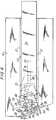
- Fig. 1 is a schematic plan view of a distal portion of a fastener housing according to the present invention;
- Fig. 2 is a top view of a portion of a pusher bar;
- Fig. 3 is a front view of a pusher element of the invention;
- Fig. 4 is a bottom view of the pusher element;
- Fig. 5 is a schematic view of a preferred, formed fastener; and
- Fig. 6 is a schematic plan view of a distal portion of the fastener housing of Fig. 1 at various stages of fastener advancement.
- A variety of actuation and fastener feeding mechanisms may be employed to advance the pusher means of the surgical instrument of the present invention to form and place fasteners. For example, the principles of the present invention may be adapted for use with a variety of handle configurations, e.g., pistol grips, scissor grips, palm grip, etc. Similarly, the fasteners of the assembly according to the invention may be stored and individually placed in the "ready" position using a variety of known mechanisms. Illustrative of such mechanisms are the pinion gear/pinion shaft mechanism and related structure disclosed in Re. 28,932 to Noiles et al., the belt mechanism and related structure disclosed in U.S. Patent No. 3,837,555 to Green, and the mechanism and related structure of U.S. Patent No. 4,204,623 to Green.
- The present invention may be fabricated as a single, unitary assembly intended for single or multiple use, or practiced in association with a reusable actuating assembly which is adapted to receive a plurality of pre-loaded cartridges, whether in a single surgical procedure or, after sterilization, in further procedures. Such choices are well within the skill of one of ordinary skill of the art and are deemed to be within the scope of the present invention.
- The remaining description shall be directed to fastener advancement and formation from the point at which a single fastener has been placed in the "ready" position, i.e., positioned adjacent pusher means adapted to advance the fastener into contact with the anvil means. As noted above, a variety of mechanisms and structure may be employed to position a fastener in the ready position.
- With reference to Fig. 1, a schematic plan view of the fastener housing in the region of fastener delivery is provided. Fastener housing 10 includes a
fastener track 12 which extends substantially along the longitudinal axis of fastener housing 10.Fastener track 12 is defined bytrack walls Fastener track 12 is sized and dimensioned to receive anunformed fastener 44, as discussed hereinbelow. - A
slot 18 is formed infastener track 12 toward the distal end of fastener housing 10.Slot 18 comprisesfirst slot region 20,second slot region 22 andthird slot region 24.First slot region 20 extends substantially along the longitudinal axis of fastener housing 10.Second slot region 22 communicates with and is angularly oriented with respect tofirst slot region 20.Third slot region 24 communicates with and is angularly oriented with respect tosecond slot region 22. More particularly,third slot region 24 extends at an angle to the longitudinal axis of fastener housing 10 which is opposite to the angle ofsecond slot region 22. Although, as illustrated, first andsecond slot regions - An
anvil 26 is positioned adjacent the outlet offastener track 12.Anvil 26 is spaced from the termination ofslot 18.Anvil 26 comprises a rigid material, e.g., stainless steel, which is sized and dimensioned to facilitate fastener formation therearound. Although Fig. 1 shows asingle anvil 26 positioned infastener track 12, additional anvil means are contemplated for incorporation into the instrument of the present invention, as for example the dual anvil sections (106,108) of U.S. Patent No. 4,127,227 to Green, - The
distal end 28 of fastener housing 10 includes anangled face 30 which is at an Angle A to the transverse axis of fastener housing 10. Angle A ofangled face 30 is generally about 5° to 45° and preferably 15° to 25° relative to the transverse axis of fastener housing 10. Angle A may be greater than 45° or less than 5° by making appropriate adjustments to slot 18 andfastener track walls Fastener track wall 14 forms an inwardly directedcam face 32 at its distal end. A corresponding, outwardly directedwall section 34 is formed at the distal end oftrack wall 15. By "inwardly" and "outwardly" directed is meant toward and away from the center line offastener track 12, respectively. Cam face 32 andwall section 34 are preferably at an Angle B to the longitudinal axis of fastener housing 10. Angles A and B are preferably substantially equal.- Inwardly directed
cam face 32 and outwardly directedwall section 34cause fastener track 12 to angle with respect to the longitudinal axis of fastener housing 10. The width offastener track 12 remains substantially constant throughout, i.e., in both its longitudinally oriented and angled regions.Third slot region 24 is typically at the same angle to the longitudinal axis ascam face 32 andwall section 34, i.e.,Angle B. Anvil 26 is positioned transverse to the angled region offastener track 12. - Referring to Figs. 2 and an
elongated pusher bar 38 is slidably received withinfastener track 12.Pusher bar 38 includes atransverse slot 40 at its distal end.Transverse slot 40 is assymetric with respect to the center line ofpusher bar 38. Theproximal end 42 ofpusher bar 38 is adapted to cooperate with an actuating mechanism which effectuates longitudinal movement ofpusher bar 38 withinfastener track 12 to advance and form afastener 44. - As shown in Figs. 3 and 4, a
U-shaped pusher element 46 includes a downwardly extendingpin 48.Pusher element 46 also includes acontact face 50 which includes distally directedpusher legs U-shaped region 56.Side wall 58 includes a longitudinally directedside face 60 and anangled abutment face 62.Pin 48 is sized and dimensioned to extend through and ride withtransverse slot 40 inpusher bar 38, and to further extend into and ride withinslot 18 infastener track 12. - Referring to Fig. 6, the interaction and cooperation of
pusher bar 38,pusher element 46,fastener track 12,slot 18 andanvil 26 will now be described. Fig. 6 shows the above elements at various stages of fastener advance.Fastener 44 is positioned distal of and in abutment withcontact face 50 ofpusher element 46. In the proximal-most pictured position ofpusher element 46,pin 48 is located withinfirst slot region 20 and withintransverse slot 40 to substantially at the center line ofpusher bar 38. - As the
pusher bar 38 is advanced distally,pin 48 enterssecond slot region 22 which causespin 48 to travel withintransverse slot 40 towardtrack wall 14. Contact between side face 60 ofpusher element 46 andtrack wall 14 prevents transverse displacement ofpusher element 46 with respect tofastener track 12 and causes counterclockwise rotation ofpusher element 46 aroundpin 48. This counterclockwise rotation brings angledabutment face 62 into contact with track wall 14 (pusher element 46 is illustrated just prior to complete rotation).Contact face 50 ofpusher element 46 thus assumes an angled orientation with respect to the longitudinal axis of fastener housing 10.Fastener 44 is brought into the same angled orientation through interaction withcontact face 50.Contact face 50 andfastener 44 are preferably oriented at an Angle B to the longitudinal axis offastener housing 12. - Further distal movement of
pusher bar 38 causespin 48 to enterthird slot region 24. Aspin 48 reachesthird slot region 24,side wall 58 ofpusher element 46 comes into contact with inwardly directedcam face 32.Pin 48 travels withintransverse slot 40 towardtrack wall 15 as it moves distally withinthird slot region 24.Fastener 44 is thus advanced through the angled portion offastener track 12.Backspan 64 offastener 44 engagesanvil 26 andpusher legs drive fastener 44 so as to bendfasteners legs 66 therearound (see also Fig. 5).Fastener 44 is fully formed at such time aspin 48 reaches the distal termination ofslot 18. - In use, the surgeon places angled
face 30 of fastener housing 10 adjacent to or against the tissue, reinforcement material or the like, to be fastened. The surgeon may, if he wishes,advance pusher bar 38 and thusfastener 44 to exposefastener legs 66 from fastener housing 10 prior to so placing fastener housing 10, to facilitate proper placement offastener 44. Thereafter,pusher bar 38 is advanced to formfastener 44 in or around the tissue and/or reinforcement material, e.g., mesh, to be fastened. - In a preferred embodiment of the invention,
fastener 44 is formed in a unique configuration which provides significant clinical advantages, particularly when used to fasten a reinforcement material to tissue, e.g., in hernia repair. The unique fastener configuration is accomplished by (i) positioninganvil 26 assymeterically with respect to the center line of the angled portion offastener track 12 and (ii) providing apusher member 42 adapted to cooperate with assymetrically positionedanvil 26 and preferably includingcontact legs unique fastener 44, the surgeon is able to expose greater lengthes offastener legs 66 to facilitate visualization and optimal placement because, when formed,legs 66 assume a substantially overlapping, longitudinally-spaced relation. - Referring to Figs. 3, 4 and 6,
contact leg 52 ofpusher member 42 has a greater width thancontact leg 54.Anvil 26 is positioned assymetrically with respect to the center line of the angled portion offastener track 12, being positioned more toward the side on whichthinner contact leg 54 travels. - As
pusher member 42 approachesanvil 26, contactlegs Fastener 44 is thus bent into the configuration shown in Fig. 5, withlegs 66 in substantially overlapping, longitudinally-spaced relation. The arcuate travel oflegs 66 as they are bent into their final configuration provides an advantageous bite into tissue and/or reinforcement material, and the overlapping, longitudinally-spaced relation provides excellent holding power. Preferablyfastener legs 66, when formed, are in a substantially parallel orientation, although the exact degree to whichfastener legs 66 are parallel will generally depend on the resilience of the substrate into which they are fastened.
Claims (17)
- A fastener-forming assembly comprising:(a) a fastener housing (10) defining a fastener track (12) having a centre line and an opening at one end adapted to permit fastener exit;(b) anvil means (26) positioned adjacent said opening, said anvil means being positioned in a transverse orientation with respect to said centre line; and(c) a fastener (44) having a backspan (64) and a pair of legs (66) extending from the backspan at either end thereof; wherein contact of said fastener with said anvil causes said backspan of said fastener to bend such that fastener legs assume a substantially over-lapping relation; the assembly being characterised in that:(d) the orientation of the anvil means with respect to said centre line is non-symmetrical, whereby the fastener legs when over-lapping are longitudinally spaced from each other.
- An assembly as claimed in claim 1, wherein said fastener-forming assembly further comprises a substantially U-shaped pusher element (46) slidably received in said fastener housing.
- An assembly as claimed in claim 2, wherein said U-shaped pusher element includes first (52) and second (54) distally directed legs and wherein said first leg is wider than said second leg.
- An assembly as claimed in any one of the preceding claims wherein the legs (66) of the fastener are straight, and the backspan (64) is longer than the anvil to permit said bending to be through substantially 90° whereby, after said bending, said fastener legs assume substantially parallel relation.
- An assembly as claimed in any one of the preceding claims wherein said anvil means (26) comprises dual anvil components.
- A surgical instrument including an assembly as claimed in claim 2, or any one of claims 3, 4 and 5 as dependent on claim 2, for placing a fastener in or on tissue, the instrument comprising:(a) pusher means (38) slidably received by said fastener housing, said pusher means comprising a pusher bar (38) which defines a longitudinal axis; and(b) said pusher element (46) slidably mounted to said pusher bar; and(c) slot means (18) in said fastener housing, wherein said pusher means co-operates with said slot means to angularly displace said pusher element with respect to said longitudinal axis as said pusher means is advanced through said fastener housing.
- An instrument as claimed in claim 6, wherein said pusher bar has a transverse slot (40) toward a distal end thereof, and wherein said pusher element includes pin means (48) adapted to travel within said transverse slot.
- An instrument as claimed in claim 7, wherein said pin means is further adapted to travel within said slot means.
- An instrument as claimed in claim 6, 7 or 8, wherein said pusher element is angularly displaced by an angle of from 5 to 45 degrees with respect to said longitudinal axis.
- An instrument as claimed in claim 9, wherein said pusher element is angularly displaced by an angle of from 15 to 25 degrees with respect to said longitudinal axis.
- An instrument as claimed in any one of claims 6 to 10, and including actuating handle means which effects distal movement of the pusher means.
- An instrument as claimed in claim 11 wherein the fastener housing is rotatable with respect to the handle means.
- An instrument as claimed in any one of claims 6 to 12 and which has an endoscopic portion which is adapted for introduction through a trocar sleeve with a diameter in a range of from 10 to 15 mm.
- An instrument as claimed in claim 13 and including internal sealing means to seal relative to an insufflated body cavity.
- An instrument as claimed in any one of claims 6 to 14 including means for preventing more than one fastener from being placed in a "ready" position.
- A surgical instrument or assembly as claimed in any one of the preceding claims, together with a plurality of fasteners (44) housed within the instrument for sequential placement by the instrument.
- A surgical instrument or assembly as claimed in any one of the preceding claims, which is suitable for endoscopic surgery, in that the anvil means is located in a portion of the instrument or assembly which can be advanced through a cannula to the site of surgery.
Priority Applications (1)
| Application Number | Priority Date | Filing Date | Title |
|---|---|---|---|
| DE9219098UDE9219098U1 (en) | 1991-05-07 | 1992-05-06 | Surgical fastening device |
Applications Claiming Priority (2)
| Application Number | Priority Date | Filing Date | Title |
|---|---|---|---|
| US696511 | 1991-05-07 | ||
| US07/696,511US5217472A (en) | 1991-05-07 | 1991-05-07 | Surgical fastening device |
Publications (3)
| Publication Number | Publication Date |
|---|---|
| EP0516988A2 EP0516988A2 (en) | 1992-12-09 |
| EP0516988A3 EP0516988A3 (en) | 1993-03-24 |
| EP0516988B1true EP0516988B1 (en) | 1997-12-29 |
Family
ID=24797371
Family Applications (1)
| Application Number | Title | Priority Date | Filing Date |
|---|---|---|---|
| EP92107625AExpired - LifetimeEP0516988B1 (en) | 1991-05-07 | 1992-05-06 | Surgical fastening device |
Country Status (5)
| Country | Link |
|---|---|
| US (1) | US5217472A (en) |
| EP (1) | EP0516988B1 (en) |
| AU (1) | AU649123B2 (en) |
| CA (1) | CA2067898C (en) |
| DE (1) | DE69223685T2 (en) |
Families Citing this family (63)
| Publication number | Priority date | Publication date | Assignee | Title |
|---|---|---|---|---|
| US5470010A (en)* | 1991-04-04 | 1995-11-28 | Ethicon, Inc. | Multiple fire endoscopic stapling mechanism |
| US5257713A (en)* | 1991-05-07 | 1993-11-02 | United States Surgical Corporation | Surgical fastening device |
| US5626587A (en) | 1992-10-09 | 1997-05-06 | Ethicon Endo-Surgery, Inc. | Method for operating a surgical instrument |
| US5601224A (en) | 1992-10-09 | 1997-02-11 | Ethicon, Inc. | Surgical instrument |
| US5662662A (en) | 1992-10-09 | 1997-09-02 | Ethicon Endo-Surgery, Inc. | Surgical instrument and method |
| US7235089B1 (en) | 1994-12-07 | 2007-06-26 | Boston Scientific Corporation | Surgical apparatus and method |
| US5868760A (en) | 1994-12-07 | 1999-02-09 | Mcguckin, Jr.; James F. | Method and apparatus for endolumenally resectioning tissue |
| DE19518796A1 (en)* | 1995-05-22 | 1996-11-28 | Hoechst Ag | Fluorophenyl-substituted alkenylcarboxylic acid guanidines, processes for their preparation, their use as medicaments or diagnostic agents and medicaments containing them |
| US6318616B1 (en) | 1998-10-23 | 2001-11-20 | United States Surgical | Surgical fastener applier |
| GB9827415D0 (en) | 1998-12-11 | 1999-02-03 | Wild Andrew M | Surgical apparatus and method for occluding a body passageway |
| US20050283189A1 (en)* | 1999-03-31 | 2005-12-22 | Rosenblatt Peter L | Systems and methods for soft tissue reconstruction |
| AU4187800A (en) | 1999-03-31 | 2000-10-16 | Peter L. Rosenblatt | Systems and methods for soft tissue reconstruction |
| US6981983B1 (en) | 1999-03-31 | 2006-01-03 | Rosenblatt Peter L | System and methods for soft tissue reconstruction |
| ES2435094T3 (en) | 2000-05-19 | 2013-12-18 | C.R. Bard, Inc. | Device and method of tissue capture and suturing |
| AU2001288462A1 (en) | 2000-08-30 | 2002-03-13 | Cerebral Vascular Applications Inc. | Medical instrument |
| US7485124B2 (en)* | 2000-10-19 | 2009-02-03 | Ethicon Endo-Surgery, Inc. | Surgical instrument having a fastener delivery mechanism |
| CA2451102C (en)* | 2001-07-09 | 2009-09-15 | Tyco Healthcare Group Lp | Right angle clip applier apparatus and method |
| US6755338B2 (en)* | 2001-08-29 | 2004-06-29 | Cerebral Vascular Applications, Inc. | Medical instrument |
| US6981979B2 (en)* | 2001-12-14 | 2006-01-03 | Enrico Nicolo | Surgical anastomotic devices |
| US6974462B2 (en) | 2001-12-19 | 2005-12-13 | Boston Scientific Scimed, Inc. | Surgical anchor implantation device |
| EP2813186B1 (en)* | 2002-04-22 | 2020-01-01 | Covidien LP | Endoscopic surgical clip |
| US20030229368A1 (en)* | 2002-04-22 | 2003-12-11 | Viola Frank J. | Endoscopic surgical clip |
| GB0305976D0 (en)* | 2003-03-14 | 2003-04-23 | Wild Andrew M | Surgical clip |
| CN1822794B (en) | 2003-05-16 | 2010-05-26 | C.R.巴德有限公司 | Single cannula, multiple needle endoscopic suturing system |
| US8105355B2 (en) | 2006-05-18 | 2012-01-31 | C.R. Bard, Inc. | Suture lock fastening device |
| US7434716B2 (en)* | 2006-12-21 | 2008-10-14 | Tyco Healthcare Group Lp | Staple driver for articulating surgical stapler |
| US8136710B2 (en)* | 2007-03-01 | 2012-03-20 | Cascade Technologies, Llc | Powered stapling device |
| US7922064B2 (en)* | 2007-05-16 | 2011-04-12 | The Invention Science Fund, I, LLC | Surgical fastening device with cutter |
| US7798385B2 (en)* | 2007-05-16 | 2010-09-21 | The Invention Science Fund I, Llc | Surgical stapling instrument with chemical sealant |
| US8485411B2 (en)* | 2007-05-16 | 2013-07-16 | The Invention Science Fund I, Llc | Gentle touch surgical stapler |
| US7823761B2 (en)* | 2007-05-16 | 2010-11-02 | The Invention Science Fund I, Llc | Maneuverable surgical stapler |
| US20080287987A1 (en)* | 2007-05-16 | 2008-11-20 | Searete Llc, A Limited Liability Corporation Of The State Of Delaware | Dispensing system for tissue sealants |
| US7832611B2 (en)* | 2007-05-16 | 2010-11-16 | The Invention Science Fund I, Llc | Steerable surgical stapler |
| US7810691B2 (en)* | 2007-05-16 | 2010-10-12 | The Invention Science Fund I, Llc | Gentle touch surgical stapler |
| US7703653B2 (en) | 2007-09-28 | 2010-04-27 | Tyco Healthcare Group Lp | Articulation mechanism for surgical instrument |
| US20090112243A1 (en)* | 2007-10-25 | 2009-04-30 | Searete Llc, A Limited Liability Corporation Of The State Of Delaware | Surgical cutter with dispensing system for tissue sealants |
| US20090112256A1 (en)* | 2007-10-30 | 2009-04-30 | Searete Llc, A Limited Liability Corporation Of The State Of Delaware | Suturing device with tissue sealant dispenser |
| US20090143816A1 (en)* | 2007-11-30 | 2009-06-04 | Searete Llc, A Limited Liability Corporation Of The State Of Delaware | Grasper with surgical sealant dispenser |
| US8870049B2 (en) | 2008-03-14 | 2014-10-28 | Transenterix, Inc. | Hernia stapler |
| MX2010009586A (en)* | 2008-03-14 | 2011-02-22 | Safestitch Medical Inc | Hernia stapler with integrated mesh manipulator. |
| WO2010081029A1 (en) | 2009-01-08 | 2010-07-15 | Rotation Medical, Inc. | Implantable tendon protection systems and related kits and methods |
| US9179910B2 (en) | 2009-03-20 | 2015-11-10 | Rotation Medical, Inc. | Medical device delivery system and method |
| AU2010256472B2 (en) | 2009-06-04 | 2015-07-09 | Rotation Medical, Inc. | Apparatus for fixing sheet-like materials to a target tissue |
| CA2763937C (en) | 2009-06-04 | 2017-05-23 | Rotation Medical, Inc. | Methods and apparatus for deploying sheet-like materials |
| US9198750B2 (en) | 2010-03-11 | 2015-12-01 | Rotation Medical, Inc. | Tendon repair implant and method of arthroscopic implantation |
| WO2012145059A1 (en) | 2011-02-15 | 2012-10-26 | Rotation Medical, Inc. | Methods and apparatus for fixing sheet-like materials to a target tissue |
| US10952783B2 (en) | 2011-12-29 | 2021-03-23 | Rotation Medical, Inc. | Guidewire having a distal fixation member for delivering and positioning sheet-like materials in surgery |
| WO2012112565A2 (en) | 2011-02-15 | 2012-08-23 | Rotation Medical, Inc. | Methods and apparatus for delivering and positioning sheet-like materials |
| AU2012355433B2 (en) | 2011-12-19 | 2016-10-20 | Rotation Medical, Inc. | Apparatus and method for forming pilot holes in bone and delivering fasteners therein for retaining an implant |
| EP2793712B1 (en) | 2011-12-19 | 2018-03-28 | Rotation Medical, Inc. | Fasteners for affixing sheet -like materials to bone or tissue |
| US9271726B2 (en) | 2011-12-19 | 2016-03-01 | Rotation Medical, Inc. | Fasteners and fastener delivery devices for affixing sheet-like materials to bone or tissue |
| US9107661B2 (en) | 2011-12-19 | 2015-08-18 | Rotation Medical, Inc. | Fasteners and fastener delivery devices for affixing sheet-like materials to bone or tissue |
| WO2013101641A2 (en) | 2011-12-29 | 2013-07-04 | Rotation Medical, Inc. | Anatomical location markers and methods of use in positioning sheet-like materials during surgery |
| EP2797532B1 (en) | 2011-12-29 | 2016-04-06 | Rotation Medical, Inc. | Apparatus for delivering and positioning sheet-like materials in surgery |
| CA2945821C (en) | 2014-05-09 | 2018-09-04 | Rotation Medical, Inc. | Medical implant delivery system for sheet-like implant |
| EP3215025B1 (en) | 2014-11-04 | 2020-12-23 | Rotation Medical, Inc. | Medical implant delivery system |
| US10123796B2 (en) | 2014-11-04 | 2018-11-13 | Rotation Medical, Inc. | Medical implant delivery system and related methods |
| AU2015343273B2 (en) | 2014-11-04 | 2017-12-14 | Rotation Medical, Inc. | Medical implant delivery system and related methods |
| CA2983341A1 (en) | 2015-05-06 | 2016-11-10 | Rotation Medical, Inc. | Medical implant delivery system and related methods |
| US10265156B2 (en) | 2015-06-15 | 2019-04-23 | Rotation Medical, Inc | Tendon repair implant and method of implantation |
| EP3397175B1 (en) | 2015-12-31 | 2021-11-24 | Rotation Medical, Inc. | Fastener delivery system |
| AU2016381936B2 (en) | 2015-12-31 | 2019-02-28 | Rotation Medical, Inc. | Medical implant delivery system and related methods |
| WO2019113292A1 (en) | 2017-12-07 | 2019-06-13 | Rotation Medical, Inc. | Medical implant delivery system and related methods |
Citations (5)
| Publication number | Priority date | Publication date | Assignee | Title |
|---|---|---|---|---|
| FR1234670A (en)* | 1959-09-08 | 1960-10-19 | Inst Rech S Sur L App Et Les I | Multi-staple device for ligation of blood vessels in deep cavities with ii-shaped metal staples |
| DE2703529A1 (en)* | 1977-01-28 | 1978-08-03 | Krupp Gmbh | IMPLANT TO CONNECT SEPARATION SITES IN LIVING TISSUE |
| EP0061867A2 (en)* | 1981-03-27 | 1982-10-06 | Minnesota Mining And Manufacturing Company | Staple and cartridge for use in a tissue-stapling device and a tissue-closing method |
| EP0354724A2 (en)* | 1988-08-09 | 1990-02-14 | Matsutani Seisakusho Co. Ltd., | Surgical stapler |
| GB2233903A (en)* | 1989-07-13 | 1991-01-23 | Vijay Kumar Choudhury | Dissecting-cum-haemostapling scissors |
Family Cites Families (61)
| Publication number | Priority date | Publication date | Assignee | Title |
|---|---|---|---|---|
| US389660A (en)* | 1888-09-18 | Metallic fastener | ||
| US3124136A (en)* | 1964-03-10 | Method of repairing body tissue | ||
| US28932A (en)* | 1860-06-26 | Railroad station-indicator | ||
| US3054406A (en)* | 1958-10-17 | 1962-09-18 | Phillips Petroleum Co | Surgical mesh |
| US3494533A (en)* | 1966-10-10 | 1970-02-10 | United States Surgical Corp | Surgical stapler for stitching body organs |
| US3643851A (en)* | 1969-08-25 | 1972-02-22 | United States Surgical Corp | Skin stapler |
| US3837555A (en)* | 1970-12-14 | 1974-09-24 | Surgical Corp | Powering instrument for stapling skin and fascia |
| DE2330182A1 (en)* | 1973-06-14 | 1975-01-02 | Wolf Gmbh Richard | PLIERS FOR SETTING TANTALUM CLIPS |
| US4027510A (en)* | 1974-05-15 | 1977-06-07 | Siegfried Hiltebrandt | Forceps |
| US4014492A (en)* | 1975-06-11 | 1977-03-29 | Senco Products, Inc. | Surgical staple |
| US4043504A (en)* | 1976-03-09 | 1977-08-23 | Senco Products, Inc. | Staple cartridge and feed means for use with a surgical stapling instrument |
| US4127227A (en)* | 1976-10-08 | 1978-11-28 | United States Surgical Corporation | Wide fascia staple cartridge |
| US4196836A (en)* | 1978-02-14 | 1980-04-08 | Senco Products Inc. | Surgical stapling instrument |
| US4256251A (en)* | 1978-04-24 | 1981-03-17 | Lawrence M. Smith | Surgical staplers and staple |
| US4204623A (en)* | 1978-07-17 | 1980-05-27 | United States Surgical Corporation | Manually powered surgical stapling instrument |
| US4261244A (en)* | 1979-05-14 | 1981-04-14 | Senco Products, Inc. | Surgical staple |
| US4403693A (en)* | 1979-09-24 | 1983-09-13 | Minnesota Mining And Manufacturing Company | Medical stapling device |
| AU534210B2 (en)* | 1980-02-05 | 1984-01-12 | United States Surgical Corporation | Surgical staples |
| US4347847A (en)* | 1980-06-06 | 1982-09-07 | Usher Francis C | Method of hernia repair |
| US4452245A (en)* | 1980-06-06 | 1984-06-05 | Usher Francis C | Surgical mesh and method |
| CA1170536A (en)* | 1980-08-25 | 1984-07-10 | United States Surgical Corporation | Surgical staples |
| US4349028A (en)* | 1980-10-03 | 1982-09-14 | United States Surgical Corporation | Surgical stapling apparatus having self-contained pneumatic system for completing manually initiated motion sequence |
| AU542936B2 (en)* | 1980-10-17 | 1985-03-28 | United States Surgical Corporation | Self centering staple |
| US4375866A (en)* | 1981-01-22 | 1983-03-08 | Edward Weck & Company, Inc. | Skin clip applier |
| US4526174A (en)* | 1981-03-27 | 1985-07-02 | Minnesota Mining And Manufacturing Company | Staple and cartridge for use in a tissue stapling device and a tissue closing method |
| DE3204522A1 (en)* | 1982-02-10 | 1983-08-25 | B. Braun Melsungen Ag, 3508 Melsungen | SURGICAL SKIN CLIP DEVICE |
| DE3204532C2 (en)* | 1982-02-10 | 1983-12-08 | B. Braun Melsungen Ag, 3508 Melsungen | Surgical skin staple |
| US4509518A (en)* | 1982-02-17 | 1985-04-09 | United States Surgical Corporation | Apparatus for applying surgical clips |
| US4802478A (en)* | 1982-03-04 | 1989-02-07 | Minnesota Mining And Manufacturing Company | Medical staple and removal method |
| US4496090A (en)* | 1982-03-10 | 1985-01-29 | Crevier Paul H | Surgical stapler |
| US4664305A (en)* | 1982-05-04 | 1987-05-12 | Blake Joseph W Iii | Surgical stapler |
| US4523707A (en)* | 1982-05-04 | 1985-06-18 | Blake Joseph W Iii | Surgical stapler |
| US4492232A (en)* | 1982-09-30 | 1985-01-08 | United States Surgical Corporation | Surgical clip applying apparatus having fixed jaws |
| US4532927A (en)* | 1983-06-20 | 1985-08-06 | Ethicon, Inc. | Two-piece tissue fastener with non-reentry bent leg staple and retaining receiver |
| US5125553A (en)* | 1987-03-02 | 1992-06-30 | Stryker Sales Corporation | Surgical suturing instrument and method |
| US4919152A (en)* | 1987-03-02 | 1990-04-24 | Ralph Ger | Method of closing the opening of a hernial sac |
| US4944443A (en)* | 1988-04-22 | 1990-07-31 | Innovative Surgical Devices, Inc. | Surgical suturing instrument and method |
| US4583670A (en)* | 1983-12-23 | 1986-04-22 | Alfredo Alvarado | Surgical stapling |
| US4618086A (en)* | 1984-03-12 | 1986-10-21 | American Cyanamid Company | Skin stapler |
| US4634035A (en)* | 1984-03-12 | 1987-01-06 | American Cyanamid Company | Skin stapler |
| DE3582079D1 (en)* | 1984-03-12 | 1991-04-18 | American Cyanamid Co | SKIN CLIP DEVICE. |
| US4607638A (en)* | 1984-04-20 | 1986-08-26 | Design Standards Corporation | Surgical staples |
| US4671279A (en)* | 1984-04-24 | 1987-06-09 | Beta Phase, Inc. | Surgical staple applying method |
| EP0185026A1 (en)* | 1984-05-07 | 1986-06-25 | PUCHY, David Peter William | Surgical stapler providing variable degree of staple closure |
| GB8422863D0 (en)* | 1984-09-11 | 1984-10-17 | Univ London | Sewing machine |
| US4616650A (en)* | 1984-07-27 | 1986-10-14 | United States Surgical Corporation | Apparatus for applying surgical clips |
| US4566620A (en)* | 1984-10-19 | 1986-01-28 | United States Surgical Corporation | Articulated surgical fastener applying apparatus |
| US4787387A (en)* | 1984-11-08 | 1988-11-29 | American Cyanamid Company | Surgical closure element |
| US4610251A (en)* | 1985-04-19 | 1986-09-09 | Kumar Sarbjeet S | Surgical staple |
| US4807628A (en)* | 1985-04-26 | 1989-02-28 | Edward Weck & Company, Inc. | Method and apparatus for storing, dispensing, and applying surgical staples |
| US4655221A (en)* | 1985-05-06 | 1987-04-07 | American Cyanamid Company | Method of using a surgical repair mesh |
| US4728020A (en)* | 1985-08-30 | 1988-03-01 | United States Surgical Corporation | Articulated surgical fastener applying apparatus |
| US4662555A (en)* | 1986-03-11 | 1987-05-05 | Edward Weck & Company, Inc. | Surgical stapler |
| US4874122A (en)* | 1986-07-14 | 1989-10-17 | Minnesota Mining And Manufacturing Company | Bent back box staple and staple closing mechanism with split actuator |
| US4821942A (en)* | 1986-09-11 | 1989-04-18 | Ophthalmic Ventures Limited Partnership | Driver for surgical microstapler |
| US4719917A (en)* | 1987-02-17 | 1988-01-19 | Minnesota Mining And Manufacturing Company | Surgical staple |
| US4747531A (en)* | 1987-03-23 | 1988-05-31 | Ethicon, Inc. | Anvil and driver assembly for a surgical skin stapling instrument |
| US4821939A (en)* | 1987-09-02 | 1989-04-18 | United States Surgical Corporation | Staple cartridge and an anvilless surgical stapler |
| US4919320A (en)* | 1988-03-07 | 1990-04-24 | Technalytics, Inc. | Surgical stapler |
| FR2629998B1 (en)* | 1988-04-14 | 1990-08-17 | Laboureau Jacques Philippe | SKIN SUTURE SURGICAL STAPLE AND TOOL FOR ITS IMPLEMENTATION |
| US4978049A (en)* | 1989-05-26 | 1990-12-18 | United States Surgical Corporation | Three staple drive member |
- 1991
- 1991-05-07USUS07/696,511patent/US5217472A/ennot_activeExpired - Lifetime
- 1992
- 1992-05-01CACA002067898Apatent/CA2067898C/ennot_activeExpired - Lifetime
- 1992-05-06EPEP92107625Apatent/EP0516988B1/ennot_activeExpired - Lifetime
- 1992-05-06DEDE69223685Tpatent/DE69223685T2/ennot_activeExpired - Lifetime
- 1992-05-06AUAU16056/92Apatent/AU649123B2/ennot_activeCeased
Patent Citations (5)
| Publication number | Priority date | Publication date | Assignee | Title |
|---|---|---|---|---|
| FR1234670A (en)* | 1959-09-08 | 1960-10-19 | Inst Rech S Sur L App Et Les I | Multi-staple device for ligation of blood vessels in deep cavities with ii-shaped metal staples |
| DE2703529A1 (en)* | 1977-01-28 | 1978-08-03 | Krupp Gmbh | IMPLANT TO CONNECT SEPARATION SITES IN LIVING TISSUE |
| EP0061867A2 (en)* | 1981-03-27 | 1982-10-06 | Minnesota Mining And Manufacturing Company | Staple and cartridge for use in a tissue-stapling device and a tissue-closing method |
| EP0354724A2 (en)* | 1988-08-09 | 1990-02-14 | Matsutani Seisakusho Co. Ltd., | Surgical stapler |
| GB2233903A (en)* | 1989-07-13 | 1991-01-23 | Vijay Kumar Choudhury | Dissecting-cum-haemostapling scissors |
Also Published As
| Publication number | Publication date |
|---|---|
| DE69223685D1 (en) | 1998-02-05 |
| AU1605692A (en) | 1992-11-12 |
| CA2067898A1 (en) | 1992-11-08 |
| DE69223685T2 (en) | 1998-06-04 |
| AU649123B2 (en) | 1994-05-12 |
| CA2067898C (en) | 2003-07-22 |
| EP0516988A3 (en) | 1993-03-24 |
| US5217472A (en) | 1993-06-08 |
| EP0516988A2 (en) | 1992-12-09 |
Similar Documents
| Publication | Publication Date | Title |
|---|---|---|
| EP0516988B1 (en) | Surgical fastening device | |
| US5257713A (en) | Surgical fastening device | |
| CA2430459C (en) | Tissue fastener having a shaft with a reduced cross-section | |
| JP6208134B2 (en) | Surgical instrument with staple reinforcing clip | |
| US7056330B2 (en) | Method for applying tissue fastener | |
| EP0503271B1 (en) | Surgical staple and endoscopic stapler | |
| EP3515329B1 (en) | Applicator instruments having articulating shafts for dispensing surgical fasteners | |
| EP1767157B1 (en) | Surgical stapling instrument having end effector gripping surfaces | |
| EP0541987B1 (en) | Apparatus for applying surgical staples to attach an object to body tissue | |
| US10568627B2 (en) | Surgical fasteners for mesh and tissue fixation | |
| DE9219098U1 (en) | Surgical fastening device |
Legal Events
| Date | Code | Title | Description |
|---|---|---|---|
| PUAI | Public reference made under article 153(3) epc to a published international application that has entered the european phase | Free format text:ORIGINAL CODE: 0009012 | |
| AK | Designated contracting states | Kind code of ref document:A2 Designated state(s):BE CH DE ES FR GB IT LI LU NL | |
| PUAL | Search report despatched | Free format text:ORIGINAL CODE: 0009013 | |
| AK | Designated contracting states | Kind code of ref document:A3 Designated state(s):BE CH DE ES FR GB IT LI LU NL | |
| 17P | Request for examination filed | Effective date:19930825 | |
| 17Q | First examination report despatched | Effective date:19950327 | |
| GRAG | Despatch of communication of intention to grant | Free format text:ORIGINAL CODE: EPIDOS AGRA | |
| GRAG | Despatch of communication of intention to grant | Free format text:ORIGINAL CODE: EPIDOS AGRA | |
| GRAH | Despatch of communication of intention to grant a patent | Free format text:ORIGINAL CODE: EPIDOS IGRA | |
| GRAH | Despatch of communication of intention to grant a patent | Free format text:ORIGINAL CODE: EPIDOS IGRA | |
| GRAA | (expected) grant | Free format text:ORIGINAL CODE: 0009210 | |
| AK | Designated contracting states | Kind code of ref document:B1 Designated state(s):BE CH DE ES FR GB IT LI LU NL | |
| PG25 | Lapsed in a contracting state [announced via postgrant information from national office to epo] | Ref country code:IT Free format text:LAPSE BECAUSE OF FAILURE TO SUBMIT A TRANSLATION OF THE DESCRIPTION OR TO PAY THE FEE WITHIN THE PRE;WARNING: LAPSES OF ITALIAN PATENTS WITH EFFECTIVE DATE BEFORE 2007 MAY HAVE OCCURRED AT ANY TIME BEFORE 2007. THE CORRECT EFFECTIVE DATE MAY BE DIFFERENT FROM THE ONE RECORDED.SCRIBED TIME-LIMIT Effective date:19971229 Ref country code:CH Free format text:LAPSE BECAUSE OF FAILURE TO SUBMIT A TRANSLATION OF THE DESCRIPTION OR TO PAY THE FEE WITHIN THE PRESCRIBED TIME-LIMIT Effective date:19971229 Ref country code:NL Free format text:LAPSE BECAUSE OF FAILURE TO SUBMIT A TRANSLATION OF THE DESCRIPTION OR TO PAY THE FEE WITHIN THE PRESCRIBED TIME-LIMIT Effective date:19971229 Ref country code:LI Free format text:LAPSE BECAUSE OF FAILURE TO SUBMIT A TRANSLATION OF THE DESCRIPTION OR TO PAY THE FEE WITHIN THE PRESCRIBED TIME-LIMIT Effective date:19971229 Ref country code:ES Free format text:THE PATENT HAS BEEN ANNULLED BY A DECISION OF A NATIONAL AUTHORITY Effective date:19971229 Ref country code:BE Free format text:LAPSE BECAUSE OF FAILURE TO SUBMIT A TRANSLATION OF THE DESCRIPTION OR TO PAY THE FEE WITHIN THE PRESCRIBED TIME-LIMIT Effective date:19971229 | |
| REG | Reference to a national code | Ref country code:CH Ref legal event code:EP | |
| REF | Corresponds to: | Ref document number:69223685 Country of ref document:DE Date of ref document:19980205 | |
| ET | Fr: translation filed | ||
| PG25 | Lapsed in a contracting state [announced via postgrant information from national office to epo] | Ref country code:LU Free format text:LAPSE BECAUSE OF NON-PAYMENT OF DUE FEES Effective date:19980506 | |
| NLV1 | Nl: lapsed or annulled due to failure to fulfill the requirements of art. 29p and 29m of the patents act | ||
| REG | Reference to a national code | Ref country code:CH Ref legal event code:PL | |
| PLBE | No opposition filed within time limit | Free format text:ORIGINAL CODE: 0009261 | |
| STAA | Information on the status of an ep patent application or granted ep patent | Free format text:STATUS: NO OPPOSITION FILED WITHIN TIME LIMIT | |
| 26N | No opposition filed | ||
| REG | Reference to a national code | Ref country code:GB Ref legal event code:IF02 | |
| PGFP | Annual fee paid to national office [announced via postgrant information from national office to epo] | Ref country code:FR Payment date:20110607 Year of fee payment:20 | |
| PGFP | Annual fee paid to national office [announced via postgrant information from national office to epo] | Ref country code:GB Payment date:20110525 Year of fee payment:20 | |
| PGFP | Annual fee paid to national office [announced via postgrant information from national office to epo] | Ref country code:DE Payment date:20110527 Year of fee payment:20 | |
| REG | Reference to a national code | Ref country code:DE Ref legal event code:R071 Ref document number:69223685 Country of ref document:DE | |
| REG | Reference to a national code | Ref country code:DE Ref legal event code:R071 Ref document number:69223685 Country of ref document:DE | |
| REG | Reference to a national code | Ref country code:GB Ref legal event code:PE20 Expiry date:20120505 | |
| PG25 | Lapsed in a contracting state [announced via postgrant information from national office to epo] | Ref country code:DE Free format text:LAPSE BECAUSE OF EXPIRATION OF PROTECTION Effective date:20120508 | |
| PG25 | Lapsed in a contracting state [announced via postgrant information from national office to epo] | Ref country code:GB Free format text:LAPSE BECAUSE OF EXPIRATION OF PROTECTION Effective date:20120505 |