EP0516573B1 - Peristaltic pump device for automatically sampling, weighing and mixing various liquids - Google Patents
Peristaltic pump device for automatically sampling, weighing and mixing various liquidsDownload PDFInfo
- Publication number
- EP0516573B1 EP0516573B1EP92440065AEP92440065AEP0516573B1EP 0516573 B1EP0516573 B1EP 0516573B1EP 92440065 AEP92440065 AEP 92440065AEP 92440065 AEP92440065 AEP 92440065AEP 0516573 B1EP0516573 B1EP 0516573B1
- Authority
- EP
- European Patent Office
- Prior art keywords
- pump body
- rotor
- weighing
- liquid
- hose
- Prior art date
- Legal status (The legal status is an assumption and is not a legal conclusion. Google has not performed a legal analysis and makes no representation as to the accuracy of the status listed.)
- Expired - Lifetime
Links
Images


Classifications
- B—PERFORMING OPERATIONS; TRANSPORTING
- B67—OPENING, CLOSING OR CLEANING BOTTLES, JARS OR SIMILAR CONTAINERS; LIQUID HANDLING
- B67D—DISPENSING, DELIVERING OR TRANSFERRING LIQUIDS, NOT OTHERWISE PROVIDED FOR
- B67D7/00—Apparatus or devices for transferring liquids from bulk storage containers or reservoirs into vehicles or into portable containers, e.g. for retail sale purposes
- B67D7/02—Apparatus or devices for transferring liquids from bulk storage containers or reservoirs into vehicles or into portable containers, e.g. for retail sale purposes for transferring liquids other than fuel or lubricants
- B—PERFORMING OPERATIONS; TRANSPORTING
- B01—PHYSICAL OR CHEMICAL PROCESSES OR APPARATUS IN GENERAL
- B01F—MIXING, e.g. DISSOLVING, EMULSIFYING OR DISPERSING
- B01F35/00—Accessories for mixers; Auxiliary operations or auxiliary devices; Parts or details of general application
- B01F35/71—Feed mechanisms
- B01F35/712—Feed mechanisms for feeding fluids
- B—PERFORMING OPERATIONS; TRANSPORTING
- B01—PHYSICAL OR CHEMICAL PROCESSES OR APPARATUS IN GENERAL
- B01L—CHEMICAL OR PHYSICAL LABORATORY APPARATUS FOR GENERAL USE
- B01L3/00—Containers or dishes for laboratory use, e.g. laboratory glassware; Droppers
- B01L3/02—Burettes; Pipettes
- B01L3/0289—Apparatus for withdrawing or distributing predetermined quantities of fluid
- B01L3/0293—Apparatus for withdrawing or distributing predetermined quantities of fluid for liquids
- G—PHYSICS
- G01—MEASURING; TESTING
- G01G—WEIGHING
- G01G17/00—Apparatus for or methods of weighing material of special form or property
- G01G17/04—Apparatus for or methods of weighing material of special form or property for weighing fluids, e.g. gases, pastes
- G01G17/06—Apparatus for or methods of weighing material of special form or property for weighing fluids, e.g. gases, pastes having means for controlling the supply or discharge
Definitions
- the subject of the present inventionis a device intended for withdrawing, weighing and automatically mixing, according to the data supplied for example by a computer, various and precious liquids, under very strict non-contamination conditions and precise weight dosing.
- document US-A-3 994 687proposes, in order to achieve the geometric dilution of a liquid, the use of a peristaltic pump comprising a plurality of parallel pipes passing under a rotor equipped with rollers pressure, one end of each of said pipes being immersed in a tank of the diluent liquid while the other end is connected to a vertical tube mounted on a movable support and opening above a receiving bottle.
- the device described in this documentdesigned to carry out the geometric dilution of the same liquid in several containers using the same diluent, cannot be suitable for producing a mixture of several liquids, in variable number.
- the device described in this documentcomprises modular elements which can be juxtaposed as a function of demand, each element or module comprising a multiplicity of pumping or transfer blocks, each secured to a bottle or other container containing the material to be transferred to a receiving bottle. .
- each pumping unitcomprises a peristaltic pump incorporating neither a motor nor a rotor, the latter being mounted together and integral with a mobile robot arm comprising a means for holding the receiving bottle while the body of the peristaltic pump incorporates a crushing pipe and is open on the one hand on the front, to allow the introduction of the roller-driven rotor driven by the motor, and on the other hand on the rear, to allow the replacement of the pipe.
- Such a deviceconstitutes a simple assembly for maintenance and use by unqualified personnel and also allows a considerable saving in products and in wiring means, since a single motor equipped with a roller-bearing rotor is sufficient to as many pump bodies as necessary, theoretically without limitation of number.
- the assembly formed by the motor and the roller-bearing rotoris positioned opposite the pump body designated by the sampling and mixing program, mates there and rotates in the direction of flow of the liquid until the desired weight is obtained, then stops then turns in the opposite direction for a revolution or two, in order to reintroduce into the initial container the liquid contained in the pipe and thus remove it from the oxidizing action of l 'air.
- the assemblydecouples and positions itself in front of another pump body according to the rest of the established program, while a device of known type then clamps the pipe so as to prevent the entry of the air and untimely product flow.
- the object of the present inventionis to propose an improvement of the device which is the subject of document WO-A-91/08451.
- the device according to the inventioncomprises, in the same way as the device described in this document, modular elements which can be juxtaposed as a function of demand, each element or module comprising a multiplicity of pumping or transfer blocks incorporating a crushing pipe and each secured to a bottle or other container containing the liquid product to be transferred to a receiving bottle.
- the device according to the inventionalso comprises a two-part peristaltic pump, the first consisting of a pump body intended to receive a crushing pipe, and the second consisting of a rotor driven by a motor secured to a movable assembly comprising a system for holding the receiving bottle, and it is essentially characterized in that each pumping block is open on the top to allow the introduction of the rotor driven by the motor.
- the rotor usedcomprises from three to six cylindrical or cylindrical grooved rollers, one or the other type of rollers which can be used depending on the ability of the pipe to twist or to escape. .
- the body of the peristaltic pumpis integral with the pumping block, which is also open on the sides to allow easy replacement of the pipe.
- the pump bodyis advantageously formed of two parts joined in an elastic manner, in order to allow its adaptation to pipes of different diameters, these diameters generally being between 3 and 6 millimeters.
- the assembly constituted by the motor and the roller-bearing rotoris positioned on the pumping block designated by the sampling and mixing program, mates there, rotates in the direction of flow of the liquid until obtaining the desired weight, stops then turns in the opposite direction for a revolution or two, in order to reintroduce the liquid contained in the pipe into the initial container and thus remove it from the oxidizing action of the air.
- the assemblydecouples and positions itself on another pumping unit according to the rest of the established program.
- the body of the peristaltic pumpis integral with the movable assembly, and the pumping block is opened from below to allow the introduction of said pump body.
- This second embodimentoffers the advantage of requiring only the use of a pump body and a rotor for a multiplicity of pumping blocks.
- the operationis the same as that of the previous embodiment, except that the assembly formed by the motor and the roller-bearing rotor moves at the same time as the pump body, which is placed under the collapsible pipe. of the pumping block while the rotor is placed above.
- a deviceclamps the pipe so as to prevent an untimely flow of the product and the entry of air.
- the device according to the inventionis completed by a simultaneous weighing device of the conventional type, advantageously connected to the computer which controls the automatic operation of the assembly according to the chosen program.
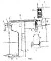
- a pumping block 10 of the devicecomprises a peristaltic pump body 1 capable of being coupled to a mobile assembly 2 comprising a roller rotor 3 equipped with four grooved rollers 33, driven in rotation by a motor 4, and a receiving device 5 intended to hold the receiving bottle 6 where the mixing of the products is carried out, this receiving device 5 incorporating a weighing device (not shown in the figure) allowing to control the quantity of liquid 11 introduced into the bottle 6.
- the pump body 1consists of two parts joined by a leaf spring 16 (visible in FIG. 2) and it incorporates a crushing pipe 8 which opens to a lateral part of the pump body 1 by a guide 17 and which is extended, inside the pump body 1, by a pouring spout 19 opening at its lower part, the pipe 8 is connected on the other hand to the outside to a tube 9 which plunges through a stopper 13 in a bottle 11 'containing the liquid 11 to be sampled and kept in a bottle holder 14 incorporating the stopper 13.
- a short tube 12 passed through the plug 13maintains the liquid 11 at ambient pressure, while a clamp 15 makes it possible to close the pipe 8 after the sampling, the clamp 15 disappears mechanically as soon as the rotor 3 is coupled to the pump body 1.
- a lever 18 pivotally mounted on the movable assembly 2 around an axis 18 'is applied to the base of the pump body 1 during the coupling operation of the rotor 3, so as to facilitate the approach and the positioning of the latter.
- the pipe 8opens out from the pump body 1 through a guide 17 placed on the side of said pump body and the withdrawn liquid 11 flows into the receiving bottle 6 through the spout 19.
- rollers 33 regularly spaced on the rotor 3create a peristaltic movement in the pipe 8, thus allowing sequential pumping of small amounts of liquid 11 in the bottle 11 ', the adjustment of the motor 4 allowing to slow or accelerate the rotation of the rotor 3, and therefore the withdrawal of the liquid 11.
- the pump body 1is secured to the movable assembly 2 via an articulated arm 28 mounted pivoting about an axis 28 ', while the pipe 8 is mounted on a support 81 capable of being coupled to the mobile assembly 2, and open for this purpose at its upper and lower ends.
- the pumping unit 20comprises the pipe 8 mounted on its support 81 and the same elements as in the first embodiment shown in FIG. 1, namely the bottle 11 'containing the liquid 11 to be sampled, held in a bottle holder 14 and provided with a pierced stopper 13 through which a short tube 12 passes, a tube 9 immersed in the liquid 11 and connected to the tube 8, which is extended, inside the pumping block 20, by a pouring spout 19 below which the receiving bottle 6 is positioned positioned on the receiving device 5 secured to the mobile assembly 2.
- the crushing pipes of the pumping blocks of the device according to the inventionmust be chosen to have good resistance to ethanol and certain corrosive liquids, and they are preferably made of a flexible plastic material with properties close to PTFE.
- the pump bodyis preferably made of aluminum alloy for reasons of lightness and rigidity, as well as ease of machining. Certain plastics can also be used, provided they are resistant to the solvents and ethyl vapors contained in the products handled.
- the device according to the inventionis particularly suitable for the automated mixing of liquids liable to be corrosive, of variable quality and viscosity and of various origins, and meets the principles laid down by precise specifications, in particular for this which concerns the need to observe strict non-contamination, both by neighboring products to be handled, and by the manufacturing agents contained in the products used.
- the device according to the inventionis particularly intended for the perfumery, cosmetology, para-pharmacy and pharmacochemical industries, but can also be used in the field of food flavorings, and be used by laboratories wishing to automate their manufacturing.
Landscapes
- Chemical & Material Sciences (AREA)
- Chemical Kinetics & Catalysis (AREA)
- Physics & Mathematics (AREA)
- General Physics & Mathematics (AREA)
- Engineering & Computer Science (AREA)
- Mechanical Engineering (AREA)
- Analytical Chemistry (AREA)
- Health & Medical Sciences (AREA)
- Clinical Laboratory Science (AREA)
- Reciprocating Pumps (AREA)
- External Artificial Organs (AREA)
- Devices For Dispensing Beverages (AREA)
- Beverage Vending Machines With Cups, And Gas Or Electricity Vending Machines (AREA)
- Automatic Analysis And Handling Materials Therefor (AREA)
- Sampling And Sample Adjustment (AREA)
Abstract
Description
Translated fromFrenchLa présente invention a pour objet un dispositif destiné à prélever, peser et mélanger automatiquement, suivant les données fournies par exemple par un ordinateur, des liquides divers et précieux, dans des conditions de non-contamination très strictes et de dosage pondéral précis.The subject of the present invention is a device intended for withdrawing, weighing and automatically mixing, according to the data supplied for example by a computer, various and precious liquids, under very strict non-contamination conditions and precise weight dosing.
Dans le domaine de la parfumerie et de la cosmétologie, ainsi que dans ceux de la pharmacie classique et de l'homéopathie, qui requièrent des dosages extrêmement précis, les opérations de mélange et de pesage sont le plus souvent effectuées manuellement dans les laboratoires, selon une certaine tradition mais en utilisant des balances électroniques de précision, qui ne permettent toutefois pas d'éliminer les risques d'erreurs, tant de dosage que de manipulation des liquides.In the field of perfumery and cosmetology, as well as in those of classical pharmacy and homeopathy, which require extremely precise dosages, the mixing and weighing operations are most often carried out manually in laboratories, according to a certain tradition but by using precision electronic scales, which however do not eliminate the risk of errors, both dosing and handling liquids.
Pour pallier cet inconvénient, le document US-A-3 994 687 propose, en vue de réaliser la dilution géométrique d'un liquide, l'utilisation d'une pompe péristaltique comprenant une pluralité de tuyaux parallèles passant sous un rotor équipé de rouleaux de pression, l'une des extrémités de chacun desdits tuyaux étant immergée dans un réservoir du liquide diluant tandis que l'autre extrémité est reliée à un tube vertical monté sur un support mobile et débouchant au-dessus d'un flacon récepteur.To overcome this drawback, document US-A-3 994 687 proposes, in order to achieve the geometric dilution of a liquid, the use of a peristaltic pump comprising a plurality of parallel pipes passing under a rotor equipped with rollers pressure, one end of each of said pipes being immersed in a tank of the diluent liquid while the other end is connected to a vertical tube mounted on a movable support and opening above a receiving bottle.
Toutefois le dispositif décrit dans ce document, conçu pour effectuer la dilution géométrique d'un même liquide dans plusieurs récipients à l'aide d'un même diluant, ne peut convenir à la réalisation d'un mélange de plusieurs liquides, en nombre variable.However, the device described in this document, designed to carry out the geometric dilution of the same liquid in several containers using the same diluent, cannot be suitable for producing a mixture of several liquids, in variable number.
Le document WO-A-91/08451, au nom de la Demanderesse (ayant une date de dépôt antérieure, mais publié après la date de dépôt de la présente invention), remédie à cette carence en proposant un dispositif qui permet d'éviter les erreurs de dosage ainsi que les risques inhérents à la manipulation de produits très coûteux et parfois corrosifs, en garantissant d'une part une économie optimale de ces produits par une plus grande sûreté et une plus grande précision de manipulation, d'autre part une grande rapidité d'exécution, ainsi qu'une meilleure sécurité sanitaire du personnel, dont le contact avec des vapeurs, notamment éthyliques, se trouve réduit.Document WO-A-91/08451, in the name of the Applicant (having an earlier filing date, but published after the filing date of the present invention), remedies this deficiency by proposing a device which makes it possible to avoid dosing errors as well as the risks inherent in the handling of very expensive and sometimes corrosive products, by guaranteeing on the one hand an optimal economy of these products by a greater safety and a greater precision of handling, on the other hand a great speed of execution, as well as improved health safety for personnel, whose contact with vapors, in particular ethyl, is reduced.
Le dispositif décrit dans ce document comporte des éléments modulaires juxtaposables en fonction de la demande, chaque élément ou module comportant une multiplicité de blocs de pompage ou de transvasement, solidaires chacun d'un flacon ou autre récipient contenant la matière à transvaser dans un flacon récepteur.The device described in this document comprises modular elements which can be juxtaposed as a function of demand, each element or module comprising a multiplicity of pumping or transfer blocks, each secured to a bottle or other container containing the material to be transferred to a receiving bottle. .
Dans ce dispositif chaque bloc de pompage comprend une pompe péristaltique n'incorporant ni moteur ni rotor, ces derniers étant montés ensemble et solidaires d'un bras de robot mobile comportant un moyen de maintien du flacon récepteur tandis que le corps de la pompe péristaltique incorpore un tuyau à écrasement et est ouvert d'une part sur l'avant, afin de permettre l'introduction du rotor porte-galets entraîné par le moteur, et d'autre part sur l'arrière, pour permettre le remplacement du tuyau.In this device, each pumping unit comprises a peristaltic pump incorporating neither a motor nor a rotor, the latter being mounted together and integral with a mobile robot arm comprising a means for holding the receiving bottle while the body of the peristaltic pump incorporates a crushing pipe and is open on the one hand on the front, to allow the introduction of the roller-driven rotor driven by the motor, and on the other hand on the rear, to allow the replacement of the pipe.
Un tel dispositif constitue un ensemble simple d'entretien et d'utilisation par du personnel non qualifié et permet en outre une économie non négligeable en produits et en moyens de câblage, puisqu'un seul moteur équipé d'un rotor porte-galets suffit pour autant de corps de pompes que nécessaire, théoriquement sans limitation de nombre.Such a device constitutes a simple assembly for maintenance and use by unqualified personnel and also allows a considerable saving in products and in wiring means, since a single motor equipped with a roller-bearing rotor is sufficient to as many pump bodies as necessary, theoretically without limitation of number.
En fonctionnement, en effet, l'ensemble formé par le moteur et le rotor porte-galets vient se positionner en face du corps de pompe désigné par le programme de prélèvement et de mélange, s'y accouple et tourne dans le sens du débit du liquide jusqu'à l'obtention du poids désiré, s'arrête alors puis tourne en sens inverse sur un tour ou deux, afin de réintroduire dans le récipient initial le liquide contenu dans le tuyau et le soustraire ainsi à l'action oxydante de l'air. A la fin de cette opération, l'ensemble se désaccouple et se positionne devant un autre corps de pompe selon la suite du programme établi, tandis qu'un dispositif de type connu pince alors le tuyau de manière à empêcher l'entrée de l'air et un écoulement intempestif du produit.In operation, in fact, the assembly formed by the motor and the roller-bearing rotor is positioned opposite the pump body designated by the sampling and mixing program, mates there and rotates in the direction of flow of the liquid until the desired weight is obtained, then stops then turns in the opposite direction for a revolution or two, in order to reintroduce into the initial container the liquid contained in the pipe and thus remove it from the oxidizing action of l 'air. At the end of this operation, the assembly decouples and positions itself in front of another pump body according to the rest of the established program, while a device of known type then clamps the pipe so as to prevent the entry of the air and untimely product flow.
La présente invention a pour but de proposer un perfectionnement du dispositif qui fait l'objet du document WO-A-91/08451.The object of the present invention is to propose an improvement of the device which is the subject of document WO-A-91/08451.
Le dispositif selon l'invention comprend, de la même manière que le dispositif décrit dans ce document, des éléments modulaires juxtaposables en fonction de la demande, chaque élément ou module comportant une multiplicité de blocs de pompage ou de transvasement incorporant un tuyau à écrasement et solidaires chacun d'un flacon ou autre récipient contenant le produit liquide à transvaser dans un flacon récepteur.The device according to the invention comprises, in the same way as the device described in this document, modular elements which can be juxtaposed as a function of demand, each element or module comprising a multiplicity of pumping or transfer blocks incorporating a crushing pipe and each secured to a bottle or other container containing the liquid product to be transferred to a receiving bottle.
Le dispositif selon l'invention comprend également une pompe péristaltique en deux parties, la première constituée d'un corps de pompe destiné à accueillir un tuyau à écrasement, et la seconde constituée d'un rotor entraîné par un moteur solidaire d'un ensemble mobile comportant un système de maintien du flacon récepteur, et il se caractérise essentiellement en ce que chaque bloc de pompage est ouvert sur le dessus pour permettre l'introduction du rotor entraîné par le moteur.The device according to the invention also comprises a two-part peristaltic pump, the first consisting of a pump body intended to receive a crushing pipe, and the second consisting of a rotor driven by a motor secured to a movable assembly comprising a system for holding the receiving bottle, and it is essentially characterized in that each pumping block is open on the top to allow the introduction of the rotor driven by the motor.
Conformément à l'invention, le rotor mis en oeuvre comporte de trois à six galets cylindriques ou cylindriques à gorge, l'un ou l'autre type de galets pouvant être utilisé selon l'aptitude du tuyau à se vriller ou à s'échapper.According to the invention, the rotor used comprises from three to six cylindrical or cylindrical grooved rollers, one or the other type of rollers which can be used depending on the ability of the pipe to twist or to escape. .
Selon un premier mode de réalisation du dispositif selon l'invention, le corps de la pompe péristaltique est solidaire du bloc de pompage, lequel est en outre ouvert sur les côtés pour permettre le remplacement aisé du tuyau.According to a first embodiment of the device according to the invention, the body of the peristaltic pump is integral with the pumping block, which is also open on the sides to allow easy replacement of the pipe.
Dans ce cas, le corps de pompe est avantageusement formé de deux parties réunies de façon élastique, afin de permettre son adaptation à des tuyaux de diamètres différents, ces diamètres se situant généralement entre 3 et 6 millimètres.In this case, the pump body is advantageously formed of two parts joined in an elastic manner, in order to allow its adaptation to pipes of different diameters, these diameters generally being between 3 and 6 millimeters.
En fonctionnement, l'ensemble constitué par le moteur et le rotor porte-galets vient se positionner sur le bloc de pompage désigné par le programme de prélèvement et de mélange, s'y accouple, tourne dans le sens du débit du liquide jusqu'à l'obtention du poids désiré, s'arrête puis tourne en sens inverse sur un tour ou deux, afin de réintroduire dans le récipient initial le liquide contenu dans le tuyau et le soustraire ainsi à l'action oxydante de l'air. A la fin de cette opération, l'ensemble se désaccouple et se positionne sur un autre bloc de pompage selon la suite du programme établi.In operation, the assembly constituted by the motor and the roller-bearing rotor is positioned on the pumping block designated by the sampling and mixing program, mates there, rotates in the direction of flow of the liquid until obtaining the desired weight, stops then turns in the opposite direction for a revolution or two, in order to reintroduce the liquid contained in the pipe into the initial container and thus remove it from the oxidizing action of the air. At the end of this operation, the assembly decouples and positions itself on another pumping unit according to the rest of the established program.
Selon un second mode de réalisation du dispositif selon l'invention, le corps de la pompe péristaltique est solidaire de l'ensemble mobile, et le bloc de pompage est ouvert par le dessous pour permettre l'introduction dudit corps de pompe.According to a second embodiment of the device according to the invention, the body of the peristaltic pump is integral with the movable assembly, and the pumping block is opened from below to allow the introduction of said pump body.
Ce second mode de réalisation offre l'avantage de ne nécessiter la mise en oeuvre que d'un corps de pompe et d'un rotor pour une multiplicité de blocs de pompage.This second embodiment offers the advantage of requiring only the use of a pump body and a rotor for a multiplicity of pumping blocks.
Le fonctionnement est le même que celui du mode de réalisation précédent, à ceci près que l'ensemble formé par le moteur et le rotor porte-galets se déplace en même temps que le corps de pompe, qui vient se placer sous le tuyau à écrasement du bloc de pompage tandis que le rotor se place au-dessus.The operation is the same as that of the previous embodiment, except that the assembly formed by the motor and the roller-bearing rotor moves at the same time as the pump body, which is placed under the collapsible pipe. of the pumping block while the rotor is placed above.
En l'absence du rotor porte-galets un dispositif pince le tuyau de manière à empêcher un écoulement intempestif du produit et l'entrée de l'air.In the absence of the roller-bearing rotor, a device clamps the pipe so as to prevent an untimely flow of the product and the entry of air.
Le dispositif selon l'invention est complété par un dispositif de pesée simultanée de type classique, avantageusement relié à l'ordinateur qui commande le fonctionnement automatique de l'ensemble selon le programme choisi.The device according to the invention is completed by a simultaneous weighing device of the conventional type, advantageously connected to the computer which controls the automatic operation of the assembly according to the chosen program.
La présente invention sera mieux comprise à la lecture de la description qui suit et qui se rapporte au dessin annexé, lequel en représente un mode de réalisation non limitatif.The present invention will be better understood on reading the description which follows and which refers to the appended drawing, which represents a non-limiting embodiment thereof.
Dans le dessin annexe :
- la figure 1 représente un premier mode de réalisation du dispositif selon l'invention, avec son rotor porte-galets en position désaccouplée.
- la figure 2 représente le corps de pompe du dispositif de la figure 1, vu de face.
- la figure 3 représente le même corps de pompe, vu en coupe, selon la ligne de coupe AA de la figure 2, en position désaccouplée avec le rotor.
- la figure 4 représente le même corps de pompe vu en coupe, en position d'accouplement avec le rotor.
- la figure 5 représente un second mode de réalisation du dispositif selon l'invention.
- la figure 6 représente le corps de pompe du dispositif de la figure 5, vu de face.
- la figure 7 représente le même coprs de pompe, vu en coupe, en position désacccouplée avec le rotor.
- la figure 8 représentre le même corps de pompe, vu en coupe, en position d'accouplement avec le rotor.
- FIG. 1 represents a first embodiment of the device according to the invention, with its roller-bearing rotor in the uncoupled position.
- 2 shows the pump body of the device of Figure 1, seen from the front.
- Figure 3 shows the same pump body, seen in section, along the section line AA of Figure 2, in the uncoupled position with the rotor.
- Figure 4 shows the same pump body seen in section, in the coupling position with the rotor.
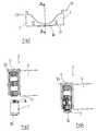
- FIG. 5 represents a second embodiment of the device according to the invention.
- 6 shows the pump body of the device of Figure 5, seen from the front.
- FIG. 7 represents the same pump body, seen in section, in the uncoupled position with the rotor.
- Figure 8 shows the same pump body, seen in section, in the coupling position with the rotor.
Si on se réfère à la figure 1, on voit qu'un bloc de pompage 10 du dispositif selon l'invention comprend un corps de pompe péristaltique 1 susceptible d'être accouplé à un ensemble mobile 2 comportant un rotor à galets 3 équipé de quatre galets à gorge 33, entraîné en rotation par un moteur 4, et un dispositif récepteur 5 destiné à maintenir le flacon récepteur 6 où le mélange des produits est effectué, ce dispositif récepteur 5 incorporant un dispositif de pesée (non représenté sur la figure) permettant de contrôler la quantité de liquide 11 introduite dans le flacon 6.Referring to FIG. 1, it can be seen that a
Le corps de pompe 1 est constitué de deux parties réunies par une lame de ressort 16 (visible sur la figure 2) et il incorpore un tuyau à écrasement 8 qui débouche à une partie latérale du corps de pompe 1 par un guide 17 et qui se prolonge, à l'intérieur du corps de pompe 1, par un bec verseur 19 débouchant à sa partie inférieure, le tuyau 8 se raccordant d'autre part à l'extérieur à un tube 9 qui plonge à travers un bouchon 13 dans un flacon 11' contenant le liquide 11 à prélever et maintenu dans un porte-flacon 14 incorporant le bouchon 13. Un tube court 12 passé à travers le bouchon 13 maintient le liquide 11 à la pression ambiante, tandis qu'une pince 15 permet de fermer le tuyau 8 après le prélèvement, la pince 15 s'effaçant mécaniquement dès l'accouplement du rotor 3 au corps de pompe 1.The
Un levier 18 monté pivotant sur l'ensemble mobile 2 autour d'un axe 18' vient s'appliquer sur la base du corps de pompe 1 pendant l'opération d'accouplement du rotor 3, de manière à faciliter l'approche et le positionnement de ce dernier.A
Si on se réfère aux figures 2, 3 et 4, on voit sur ces figures le corps de pompe 1 de la pompe péristaltique formé de deux parties réunies par une lame de ressort 16, fixé au support 14 au moyen de vis passant par deux orifices 21 et renfermant le tuyau 8 disposé dans deux guides circulaires 17.If we refer to Figures 2, 3 and 4, we see in these figures the
Le tuyau 8 débouche du corps de pompe 1 par un guide 17 disposé sur le côté dudit corps de pompe et le liquide 11 prélevé s'écoule dans le flacon récepteur 6 à travers le bec verseur 19.The
Les galets 33 régulièrement espacés sur le rotor 3 permettent de créer un mouvement péristaltique dans le tuyau 8, autorisant ainsi le pompage séquentiel de petites quantités de liquide 11 dans le flacon 11', le réglage du moteur 4 permettant de ralentir ou d'accélérer la rotation du rotor 3, et donc le prélèvement du liquide 11.The
Si on se réfère à la figure 5, on voit que dans ce mode de réalisation le corps de pompe 1 est solidarisé à l'ensemble mobile 2 par l'intermédiaire d'un bras articulé 28 monté pivotant autour d'un axe 28', tandis que le tuyau 8 est monté sur un support 81 susceptible d'être accouplé à l'ensemble mobile 2, et ouvert à cet effet à ses extrémités supérieure et inférieure.If we refer to Figure 5, we see that in this embodiment the
Dans ce mode de réalisation, le bloc de pompage 20 comprend le tuyau 8 monté sur son support 81 et les mêmes éléments que dans le premier mode de réalisation représenté à la figure 1, à savoir le flacon 11' contenant le liquide 11 à prélever, maintenu dans un porte-flacon 14 et muni d'un bouchon percé 13 à travers lequel passent un tube court 12, un tube 9 plongeant dans le liquide 11 et raccordé au tube 8, lequel est prolongé, à l'intérieur du bloc de pompage 20, par un bec verseur 19 en-dessous duquel vient se positionner le flacon récepteur 6 disposé sur le dispositif récepteur 5 solidaire de l'ensemble mobile 2.In this embodiment, the
Si on se réfère aux figures 6, 7 et 8, on retrouve sur ces figures le corps de pompe 1 solidaire du bras articulé 28, le tuyau 8 sur son support 81, et le rotor 3 avec ses galets 33, solidarisé au moteur 4.If we refer to Figures 6, 7 and 8, we find in these figures the
Les tuyaux à écrasement des blocs de pompage du dispositif selon l'invention doivent être choisis pour présenter une bonne résistance à l'éthanol et à certains liquides corrosifs, et ils sont de préférence réalisés en une matière plastique souple aux propriétés proches du PTFE.The crushing pipes of the pumping blocks of the device according to the invention must be chosen to have good resistance to ethanol and certain corrosive liquids, and they are preferably made of a flexible plastic material with properties close to PTFE.
Le corps de pompe est de préférence réalisé en alliage d'aluminium pour des raisons de légèreté et de rigidité, ainsi que de facilité d'usinage. Certaines matières plastiques peuvent être également utilisées sous réserve de leur bonne tenue aux solvants et aux vapeurs éthyliques contenus dans les produits manipulés.The pump body is preferably made of aluminum alloy for reasons of lightness and rigidity, as well as ease of machining. Certain plastics can also be used, provided they are resistant to the solvents and ethyl vapors contained in the products handled.
Le dispositif selon l'invention est particulièrement adapté au mélange automatisé de liquides susceptibles d'être corrosifs, de qualité et de viscosité variables et d'origines diverses, et répond aux principes édictés par un cahier des charges précis, notamment pour ce qui concerne la nécessité d'observer une non-contamination stricte, tant par les produits voisins devant être manipulés, que par les agents de fabrication contenus dans les produits utilisés.The device according to the invention is particularly suitable for the automated mixing of liquids liable to be corrosive, of variable quality and viscosity and of various origins, and meets the principles laid down by precise specifications, in particular for this which concerns the need to observe strict non-contamination, both by neighboring products to be handled, and by the manufacturing agents contained in the products used.
Le dispositif selon l'invention est particulièrement destiné aux industries de la parfumerie, de la cosmétologie, de la para-pharmacie et de la pharmacochimie, mais peut être également utilisé dans le domaine des produits aromatiques alimentaires, et être mis en oeuvre par les laboratoires désirant automatiser leurs fabrications.The device according to the invention is particularly intended for the perfumery, cosmetology, para-pharmacy and pharmacochemical industries, but can also be used in the field of food flavorings, and be used by laboratories wishing to automate their manufacturing.
Claims (6)
- Device allowing sundry and expensive liquids (11) kept in bottles (11') to be automatically tapped, weighed and mixed, comprising a number of pumping units (10, 20) activated by a two part peristaltic pump, the first part made up of a pump body (1) designed to take a collapsible hose (8) and the second made up of a rotor (3) driven by a motor (4) which is integral with a movable unit (2) with which a receiving device (5) which carries a receiving flask (6) designed to successively take the tapped liquids (11), whereby the said receiving device (5) incorporates a weighing device enabling the quantity of liquid (11) entering the flask (6) to be checked, each pumping unit (10, 20) being open at the top to take the rotor (3) for the purposes of attaching the movable unit (2) to the pump body (1).
- Device according to claim 1, characterised in that the pump body (1) is integral with the pumping unit (10) and incorporates the hose (8).
- Device according to claim 2, characterised in that each pump body (1) is made up of two parts joined by a resilient means (16).
- Device according to claim 1, characterised in that the pump body (1) is integral with the movable unit (2) to which it is attached via an articulated arm (28) mounted so that it pivots around an axis (28'), the hose (8) being fitted on a support (81) which is open at the bottom to allow the said pump body (1) to be introduced.
- Device according to any one of the previous claims, characterised in that a clamp (15) closes the hose (8) after the liquid (11) has been tapped, the said clamp (15) being made to move aside mechanically as soon as the rotor (3) is introduced into the pump body (1).
- Device according to any one of the previous claims, characterised in that the rotor (3) comprises from three to six cylindrical rollers (33), with or without a neck.
Applications Claiming Priority (2)
| Application Number | Priority Date | Filing Date | Title |
|---|---|---|---|
| FR9106705AFR2677008B1 (en) | 1991-05-31 | 1991-05-31 | PERISTALTIC PUMP DEVICE FOR AUTOMATICALLY TAKING, WEIGHING AND MIXING LIQUIDS. |
| FR9106705 | 1991-05-31 |
Publications (2)
| Publication Number | Publication Date |
|---|---|
| EP0516573A1 EP0516573A1 (en) | 1992-12-02 |
| EP0516573B1true EP0516573B1 (en) | 1996-09-04 |
Family
ID=9413426
Family Applications (1)
| Application Number | Title | Priority Date | Filing Date |
|---|---|---|---|
| EP92440065AExpired - LifetimeEP0516573B1 (en) | 1991-05-31 | 1992-05-29 | Peristaltic pump device for automatically sampling, weighing and mixing various liquids |
Country Status (5)
| Country | Link |
|---|---|
| EP (1) | EP0516573B1 (en) |
| AT (1) | ATE142330T1 (en) |
| DE (1) | DE69213330T2 (en) |
| ES (1) | ES2094329T3 (en) |
| FR (1) | FR2677008B1 (en) |
Families Citing this family (6)
| Publication number | Priority date | Publication date | Assignee | Title |
|---|---|---|---|---|
| DE69709768T2 (en)* | 1996-09-06 | 2002-07-18 | Jean Pierre Solignac | METHOD, DEVICE AND PLANT FOR DISPENSING QUANTITY OF LIQUID |
| FR2753190B1 (en)* | 1996-09-06 | 1998-11-13 | Solignac Jean Pierre | DEVICES INTENDED FOR THE AUTOMATIC SAMPLING, BY GRAVITY OR UNDER PRESSURE, OF VERY PRECISE QUANTITIES OF LIQUIDS, AND ALLOWING, AMONG OTHERS, THE AUTOMATIC PRODUCTION OF COMPOSITIONS |
| JP3679004B2 (en)* | 1998-12-30 | 2005-08-03 | ザ・ビー・オー・シー・グループ・インコーポレイテッド | Liquid chemical substance delivery system and delivery method |
| CN106955617B (en)* | 2017-04-07 | 2022-09-13 | 长沙湘智离心机仪器有限公司 | RC-12 automatic counterweight liquid adding instrument |
| CN111780837B (en)* | 2020-06-04 | 2021-09-10 | 安徽圣仁电子科技有限公司 | Electronic analysis balance for mass measurement |
| CN115430175B (en)* | 2022-09-20 | 2023-06-23 | 潍坊奥奇生物科技有限公司 | A plant source fungicide production preparation mixing extraction device |
Family Cites Families (6)
| Publication number | Priority date | Publication date | Assignee | Title |
|---|---|---|---|---|
| US4473173A (en)* | 1983-01-10 | 1984-09-25 | Applied Color Systems, Inc. | Apparatus and method for low volume dispensing |
| DE3346102C2 (en)* | 1983-12-21 | 1986-04-03 | Bühler-Miag GmbH, 3300 Braunschweig | Device for automated weighing |
| US4552516A (en)* | 1984-06-15 | 1985-11-12 | Cole-Parmer Instrument Company | Peristaltic pump |
| EP0173846A1 (en)* | 1984-08-07 | 1986-03-12 | Abbott Laboratories | Removable peristaltic pump head |
| FR2655092B1 (en)* | 1989-11-24 | 1994-07-08 | Bernard Vilbert | OPEN PERISTALTIC PUMP WITH DECOUPLABLE ROTOR FOR PERFUMER ROBOT. |
| FR2665092B1 (en)* | 1990-07-24 | 1995-02-03 | Gamet Precision | TIGHTENING CHUCK FOR MACHINE TOOL. |
- 1991
- 1991-05-31FRFR9106705Apatent/FR2677008B1/ennot_activeExpired - Fee Related
- 1992
- 1992-05-29EPEP92440065Apatent/EP0516573B1/ennot_activeExpired - Lifetime
- 1992-05-29DEDE69213330Tpatent/DE69213330T2/ennot_activeExpired - Lifetime
- 1992-05-29ATAT92440065Tpatent/ATE142330T1/ennot_activeIP Right Cessation
- 1992-05-29ESES92440065Tpatent/ES2094329T3/ennot_activeExpired - Lifetime
Also Published As
| Publication number | Publication date |
|---|---|
| FR2677008A1 (en) | 1992-12-04 |
| EP0516573A1 (en) | 1992-12-02 |
| FR2677008B1 (en) | 1996-12-20 |
| ES2094329T3 (en) | 1997-01-16 |
| DE69213330T2 (en) | 1997-04-24 |
| ATE142330T1 (en) | 1996-09-15 |
| DE69213330D1 (en) | 1996-10-10 |
Similar Documents
| Publication | Publication Date | Title |
|---|---|---|
| WO2019170548A1 (en) | Post-mixing beverage dispenser having pressurizable ingredient containers | |
| FR2607479A1 (en) | DEVICE FOR GRIPPING AND RETAINING OBJECTS, SUCH AS, FOR EXAMPLE, CONTAINERS, TO A CONVEYOR, AND CONVEYOR EQUIPPED WITH SAID DEVICE | |
| EP1474331A1 (en) | Installation for filling containers according to variable product compositions | |
| EP0516573B1 (en) | Peristaltic pump device for automatically sampling, weighing and mixing various liquids | |
| FR2720824A1 (en) | Method for online control of the weight of capsules and relative apparatus. | |
| FR2568703A1 (en) | DISPENSING APPARATUS DISPENSING TABS CONTAINING DRINKS MANUFACTURED INSTANTLY | |
| EP0218619A1 (en) | Granule dispensing apparatus, particularly for a tube of homoeopathic drugs, and method for the utilization thereof | |
| EP1353155A1 (en) | Method and apparatus for continuous weighing of articles and corresponding installation for calibrating shellfish | |
| WO1991008451A1 (en) | Device for automatically sampling, weighing and mixing various expensive liquids | |
| EP1910186A1 (en) | Anti-filling device | |
| WO2009144226A1 (en) | Device for diluting a sample | |
| EP0653486B1 (en) | Machine for the treatment of wine by the champagne process | |
| FR2744101A1 (en) | Plastics stopper for condiment container | |
| EP0251960B1 (en) | Dispenser for hot and cold beverages prepared with a hydrosoluble extract | |
| FR2901694A3 (en) | Pill supporting product e.g. capsule, amount counting device, has sliding plate guided in its displacement according to required quantity of products so that products fall into lower element from wells | |
| EP2786102B1 (en) | Device for dispensing powder, cap for such a device and workstation comprising such a device | |
| EP4016046B1 (en) | Device for gravimetric dilution of a sample with a predetermined amount of liquid and corresponding method | |
| EP3917363A1 (en) | Device for dispensing bulk products | |
| EP0337146B1 (en) | Dispenser for pills, tablets or the like | |
| EP0334729A1 (en) | Article dispenser with reciprocating motion | |
| EP0187774A1 (en) | Conditioning belt for siphon type sprinklers | |
| EP0859944B1 (en) | Powder dispenser | |
| EP4196754A1 (en) | Fluid product dispensing mechanism intended for a product dispensing machine, and associated machine | |
| WO2024141472A1 (en) | Bulk dispensing machine | |
| FR2723350A1 (en) | DEVICE FOR COLLECTING A POWDER CONTAINED IN A TANK |
Legal Events
| Date | Code | Title | Description |
|---|---|---|---|
| PUAI | Public reference made under article 153(3) epc to a published international application that has entered the european phase | Free format text:ORIGINAL CODE: 0009012 | |
| AK | Designated contracting states | Kind code of ref document:A1 Designated state(s):AT BE CH DE DK ES FR GB GR IT LI LU MC NL PT SE | |
| 17P | Request for examination filed | Effective date:19930503 | |
| 17Q | First examination report despatched | Effective date:19940310 | |
| RAP1 | Party data changed (applicant data changed or rights of an application transferred) | Owner name:SOLIGNAC INDUSTRIES | |
| GRAH | Despatch of communication of intention to grant a patent | Free format text:ORIGINAL CODE: EPIDOS IGRA | |
| GRAA | (expected) grant | Free format text:ORIGINAL CODE: 0009210 | |
| AK | Designated contracting states | Kind code of ref document:B1 Designated state(s):AT BE CH DE DK ES FR GB GR IT LI LU MC NL PT SE | |
| PG25 | Lapsed in a contracting state [announced via postgrant information from national office to epo] | Ref country code:GR Free format text:LAPSE BECAUSE OF FAILURE TO SUBMIT A TRANSLATION OF THE DESCRIPTION OR TO PAY THE FEE WITHIN THE PRESCRIBED TIME-LIMIT Effective date:19960904 Ref country code:DK Effective date:19960904 Ref country code:AT Effective date:19960904 | |
| REF | Corresponds to: | Ref document number:142330 Country of ref document:AT Date of ref document:19960915 Kind code of ref document:T | |
| REF | Corresponds to: | Ref document number:69213330 Country of ref document:DE Date of ref document:19961010 | |
| ITF | It: translation for a ep patent filed | ||
| PG25 | Lapsed in a contracting state [announced via postgrant information from national office to epo] | Ref country code:SE Effective date:19961204 Ref country code:PT Effective date:19961204 | |
| GBT | Gb: translation of ep patent filed (gb section 77(6)(a)/1977) | Effective date:19961205 | |
| REG | Reference to a national code | Ref country code:ES Ref legal event code:FG2A Ref document number:2094329 Country of ref document:ES Kind code of ref document:T3 | |
| PLBE | No opposition filed within time limit | Free format text:ORIGINAL CODE: 0009261 | |
| 26N | No opposition filed | ||
| PG25 | Lapsed in a contracting state [announced via postgrant information from national office to epo] | Ref country code:MC Effective date:19971130 | |
| REG | Reference to a national code | Ref country code:FR Ref legal event code:TP | |
| PGFP | Annual fee paid to national office [announced via postgrant information from national office to epo] | Ref country code:BE Payment date:19990716 Year of fee payment:8 | |
| PG25 | Lapsed in a contracting state [announced via postgrant information from national office to epo] | Ref country code:BE Free format text:LAPSE BECAUSE OF NON-PAYMENT OF DUE FEES Effective date:20000531 | |
| BERE | Be: lapsed | Owner name:SOLIGNAC INDUSTRIES Effective date:20000531 | |
| REG | Reference to a national code | Ref country code:FR Ref legal event code:ST | |
| REG | Reference to a national code | Ref country code:FR Ref legal event code:RN | |
| REG | Reference to a national code | Ref country code:GB Ref legal event code:IF02 | |
| REG | Reference to a national code | Ref country code:CH Ref legal event code:NV Representative=s name:BOVARD AG PATENTANWAELTE | |
| REG | Reference to a national code | Ref country code:FR Ref legal event code:FC | |
| REG | Reference to a national code | Ref country code:CH Ref legal event code:PFA Owner name:SOLIGNAC INDUSTRIES Free format text:SOLIGNAC INDUSTRIES#PARC INDUSTRIELLE ET TECHNOLOGIQUE DE LA POMPIGNANE, RUE DE LA VIEILLE POSTE, BP 1021#F-34006 MONTPELLIER CEDEX (FR) -TRANSFER TO- SOLIGNAC INDUSTRIES#PARC INDUSTRIELLE ET TECHNOLOGIQUE DE LA POMPIGNANE, RUE DE LA VIEILLE POSTE, BP 1021#F-34006 MONTPELLIER CEDEX (FR) | |
| PGFP | Annual fee paid to national office [announced via postgrant information from national office to epo] | Ref country code:ES Payment date:20110511 Year of fee payment:20 Ref country code:FR Payment date:20110518 Year of fee payment:20 Ref country code:CH Payment date:20110530 Year of fee payment:20 Ref country code:LU Payment date:20110531 Year of fee payment:20 | |
| PGFP | Annual fee paid to national office [announced via postgrant information from national office to epo] | Ref country code:GB Payment date:20110511 Year of fee payment:20 Ref country code:NL Payment date:20110601 Year of fee payment:20 | |
| PGFP | Annual fee paid to national office [announced via postgrant information from national office to epo] | Ref country code:IT Payment date:20110527 Year of fee payment:20 | |
| PGFP | Annual fee paid to national office [announced via postgrant information from national office to epo] | Ref country code:DE Payment date:20110629 Year of fee payment:20 | |
| REG | Reference to a national code | Ref country code:DE Ref legal event code:R071 Ref document number:69213330 Country of ref document:DE | |
| REG | Reference to a national code | Ref country code:NL Ref legal event code:V4 Effective date:20120529 Ref country code:DE Ref legal event code:R071 Ref document number:69213330 Country of ref document:DE | |
| REG | Reference to a national code | Ref country code:CH Ref legal event code:PL | |
| REG | Reference to a national code | Ref country code:GB Ref legal event code:PE20 Expiry date:20120528 | |
| PG25 | Lapsed in a contracting state [announced via postgrant information from national office to epo] | Ref country code:DE Free format text:LAPSE BECAUSE OF EXPIRATION OF PROTECTION Effective date:20120530 | |
| PG25 | Lapsed in a contracting state [announced via postgrant information from national office to epo] | Ref country code:GB Free format text:LAPSE BECAUSE OF EXPIRATION OF PROTECTION Effective date:20120528 | |
| REG | Reference to a national code | Ref country code:ES Ref legal event code:FD2A Effective date:20121207 | |
| PG25 | Lapsed in a contracting state [announced via postgrant information from national office to epo] | Ref country code:ES Free format text:LAPSE BECAUSE OF EXPIRATION OF PROTECTION Effective date:20120530 |