EP0516130A2 - Circuit for measuring battery current - Google Patents
Circuit for measuring battery currentDownload PDFInfo
- Publication number
- EP0516130A2 EP0516130A2EP92109066AEP92109066AEP0516130A2EP 0516130 A2EP0516130 A2EP 0516130A2EP 92109066 AEP92109066 AEP 92109066AEP 92109066 AEP92109066 AEP 92109066AEP 0516130 A2EP0516130 A2EP 0516130A2
- Authority
- EP
- European Patent Office
- Prior art keywords
- resistor
- operational amplifier
- input terminal
- battery
- current
- Prior art date
- Legal status (The legal status is an assumption and is not a legal conclusion. Google has not performed a legal analysis and makes no representation as to the accuracy of the status listed.)
- Granted
Links
Images


Classifications
- G—PHYSICS
- G01—MEASURING; TESTING
- G01R—MEASURING ELECTRIC VARIABLES; MEASURING MAGNETIC VARIABLES
- G01R31/00—Arrangements for testing electric properties; Arrangements for locating electric faults; Arrangements for electrical testing characterised by what is being tested not provided for elsewhere
- G01R31/36—Arrangements for testing, measuring or monitoring the electrical condition of accumulators or electric batteries, e.g. capacity or state of charge [SoC]
- G01R31/382—Arrangements for monitoring battery or accumulator variables, e.g. SoC
Definitions
- the present inventionrelates to a current measuring circuit for measuring discharging current and charging current of a battery, which is selectively connected to a load such as an electronic apparatus or the like and a battery charger.
- an object of the present inventionis to provide a current measuring circuit capable of measuring battery discharging current and charging current over a wide range from a small current to a large current.
- Another object of the present inventionis to provide a current measuring circuit capable of correctly measuring the battery discharging current and charging current with an economical structure not using expensive parts.
- a current measuring circuitfor measuring discharging current and charging current of a battery comprising a first battery, which is selectively connected to a load and a charger; a resistor connected in series with the first battery having a sufficiently low resistance value as not to substantially restrain the output current from the first battery; and a first differential amplifier for amplifying a potential difference between two ends of the resistor; in which the first differential amplifier comprises a first operational amplifier, a first resistor connected between one end of the resistor and one input terminal of the first operational amplifier, a second resistor connected between the one input terminal and the output terminal of the first operational amplifier, a third resistor connected between the other end of the resistor and the other input terminal of the first operational amplifier, and a fourth resistor connected between the other input terminal of the first operational amplifier and ground, and in which the resistance value of the first resistor is set equal to the resistance value of the third resistor and the resistance value of the second resistor is set equal to the resistance value of the fourth resistor.
- the current measuring circuitis provided with a short-circuiting means for short-circuiting the one input terminal and the other input terminal of the first operational amplifier, so that the output voltage of the first operational amplifier in such short-circuited state, i.e., the offset/drift voltage of the operational amplifier, is obtained.
- this offset/drift voltagefor correcting the output voltage from the first operational amplifier at the time of current measurement, it becomes possible to attain accurate measurement of the discharging current and charging current of the battery without using an expensive operational amplifier of a low offset/low drift type.
- the current measuring circuitis provided with a fifth resistor connected in parallel with the second resistor, a first switch connected in series with the fifth resistor and in parallel with the second resistor, a sixth resistor connected in parallel with the fourth resistor, and a second switch connected in series with the sixth resistor and in parallel with the fourth resistor. Then, by closing the first and second switches, the gain of the first operational amplifier can be decreased and, hence, the amplification factor of the first differential amplifier can be made smaller. By switching the gains of the operational amplifier as described above, it becomes possible to achieve measurement of a wide range of currents from a small current to a large current.
- Reference numeral 10denotes a rechargeable battery such as a nickel-cadmium battery.
- a switch 22By connecting a switch 22 to the side of a load 20 such as a portable telephone set, the load 20 comes to be driven by the battery 10.
- the switch 22When the switch 22 is connected to the side of a battery charger 21, the battery 10 is charged.
- the resistor R AOn the positive electrode side of the battery 10, there is connected a resistor R A in series with the battery.
- the resistor R Ahas a sufficiently low resistance value as not to virtually restrain the output current from the battery.
- the resistance value of the resistor R Ais set below 0.1 ⁇ .
- the differential amplifier 1acomprises an operational amplifier 2. There are connected a first resistor R1 between one input terminal (the inverting input terminal '-' in FIG. 1) of the operational amplifier 2 and one end of the resistor R A , a second resistor R2 between the inverting input terminal '-' and the output terminal of the operational amplifier 2, a third resistor R3 between the other input terminal (the noninverting input terminal '+' in FIG. 1) of the operational amplifier 2 and the other end of the resistor R A , and a fourth resistor R4 between the noninverting input terminal '+' of the operational amplifier 2 and ground 3.
- a first resistor R1between one input terminal (the inverting input terminal '-' in FIG. 1) of the operational amplifier 2 and one end of the resistor R A
- a second resistor R2between the inverting input terminal '-' and the output terminal of the operational amplifier 2
- a third resistor R3between the other input terminal (the noninverting input terminal '+' in FIG
- the differential amplifier 1aamplifies the voltage V3 applied thereto by the factor R2/R1 and outputs the amplified voltage from its output terminal 12 as a voltage V0.
- the output voltage V0becomes a positive or a negative voltage depending on the direction of the current with respect to the battery 10.
- the voltage V0becomes positive when the current flows out of the battery 10 in the discharging direction (in the direction of the arrow Y1) and becomes negative when the current flows in the charging direction (in the direction of the arrow Y2).
- the discharging current or charging current of the battery 10can be measured.
- the output voltage V0becomes positive or negative, it is required to apply a bias voltage to the A/D converter circuit in the measuring apparatus for determining the positive or negative polarity of the voltage V0.
- operating power-supply voltagesare applied to the positive power-supply terminal 13 and the negative power-supply terminal 14 of the operational amplifier 2.
- the positive power-supply voltagea positive voltage higher than the sum of the voltage of the battery 10 and the voltage of the potential difference V3 is required, and as the negative power-supply voltage, a negative voltage lower than - V3 is required.
- the positive power-supply terminal 13is connected with a positive power supply, not shown, to supply such a positive voltage
- the negative power-supply terminal 14is connected with a negative power supply, not shown, to supply such a negative voltage.
- the current I1flows in the direction of the arrow Y1 and thereby a very small potential difference V3 is produced between both ends of the resistor R A .
- the very small potential difference V 3is multiplied in the differential amplifier 1a by the factor R2/R1 and output from the output terminal 12 as the voltage V0.
- the discharging current I1 of the battery 10can be measured by measuring the output voltage V0.
- the switch 22is connected to the side of the charger 21 and the battery 10 is charged.
- the charging current I1decreases and, hence, the output voltage V0 of the differential amplifier 1a lowers. Therefore, the timing at which the battery 10 is fully charged can be determined by observing the output voltage V0.
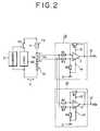
- FIG. 2there is shown a current measuring circuit of a second embodiment of the present invention.
- the current measuring circuit in this embodimentis composed of two sets of the differential amplifiers 1a shown in FIG. 1.
- a single prime (')is attached to reference numerals of one differential amplifier.
- the current measuring circuit of the present embodimentis arranged by interconnecting differential amplifiers 1a and 1a'.
- One end of the resistor R1 of the differential amplifier 1ais connected with one end of the resistor R3' of the differential amplifier 1a', while one end of the resistor R3 is connected with one end of the resistor R1'.
- the negative power-supply terminals 14 and 14' of the operational amplifiers 2 and 2'are connected with ground 3.
- the output voltage V01 of the differential amplifier 1abecomes 0 volt
- the voltage V3 of the potential differenceis amplified by the factor R2'/R1' and this voltage is output from the output terminal 12' as a positive voltage V02.
- the discharging current or charging current of the battery 10can be measured. Since measurement of only positive voltage is made in the present embodiment, negative power supplies as the operating power supplies for the operational amplifiers 2 and 2' are not required. That is, the negative power-supply voltage can be 0 V. Therefore, the negative power-supply terminals 14 and 14' of the operational amplifiers 2 and 2' can be connected to ground 3 as described above. Thus, the negative power supply can be eliminated and, hence, the power supply circuit can be simplified.
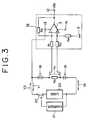
- FIG. 3there is shown a current measuring circuit of a third embodiment of the present invention.
- the battery 10 in the first and second embodimentsis divided into two batteries 15 and 16 and the resistor R A is connected between the batteries 15 and 16 in series with them.
- the positive power-supply terminal 13is connected with the positive side of the battery 16.
- the positive power-supply voltage as the operating power supply for the operational amplifier 2is only required to be a voltage higher than the sum of the voltage of the battery 15 and the voltage of the potential difference V4. Therefore, as shown in FIG. 3, the positive power-supply terminal 13 can be connected to the positive side of the battery 16 to thereby utilize the battery voltage.
- a separate positive power supplycan be eliminated and, hence, the power supply circuit can be simplified.
- FIG. 4there is shown a current measuring circuit of a fourth embodiment of the present invention.
- the current measuring circuit of this embodimentis arranged by adding a differential amplifier 1a' to the current measuring circuit shown in FIG. 3. More specifically, one end of a resistor R3' of the differential amplifier 1a' is connected to one end of the resistor R1 of the differential amplifier 1a and one end of a resistor R1' is connected to one end of the resistor R3, and a positive power-supply terminal 13' of an operational amplifier 2' is connected to the positive side of the battery 16 the same as the positive power-supply terminal 13 of the operational amplifier 2.
- a positive output voltage V04is output from the output terminal 12 of the differential amplifier 1a when a discharging current flows out of the batteries 15 and 16, while a positive output voltage V05 is output from the output terminal 12' of the differential amplifier 1a' when the batteries 15 and 16 are charged by the charger 21.
- the current flowing whether in the discharging direction or in the charging directioncan be measured as a positive voltage.
- the negative power-supply voltages for the operational amplifiers 2 and 2'can be 0 V and, hence, the negative power-supply terminals 14 and 14' can be connected to ground to eliminate the negative power supply.
- voltages of the batteries 15 and 16can be utilized as the positive power supplies for the operational amplifiers 2 and 2', no positive and negative power-supply apparatuses are required to be additionally provided for driving the operational amplifiers 2 and 2'.
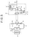
- FIG. 5there is shown a current measuring circuit of a fifth embodiment of the present invention.
- the differential amplifier 1b in this embodimentis arranged by adding a fifth resistor R5 and a sixth resistor R6 to the differential amplifier 1a shown in FIG. 1. More specifically, the fifth resistor R5 is connected in parallel with the second resistor R2 through a first switch 4 and the sixth resistor R6 is connected in parallel with the fourth resistor R4 through a second switch 5. Further, the first and second switches 4 and 5 are adapted to be turned on/off responding to a first control signal 6 output from a control means, not shown.
- the resistance value determining the gain of the operational amplifier 2becomes ⁇ R2 ⁇ R5/(R2 + R5 ) ⁇ /R1, which is smaller than the resistance value determining the gain R2/R1 in the previous state.
- the gain of the operational amplifier 2can be decreased and, hence, the amplification factor of the differential amplifier 1b can be made smaller.
- the above described meritcan be equally obtained by a sixth embodiment to an eighth embodiment shown in FIG. 6 to FIG. 8.
- the sixth embodiment shown in FIG. 6is proved, from its comparison with the second embodiment shown in FIG. 2, to be using differential amplifiers 1b and 1b' in place of the differential amplifiers 1a and 1a' in the second embodiment.
- the seventh embodiment shown in FIG. 7is proved, from its comparison with the third embodiment shown in FIG. 3, to be using a differential amplifier 1b in place of the differential amplifier 1a in the third embodiment.
- the eighth embodiment shown in FIG. 8is proved, from its comparison with the fourth embodiment shown in FIG. 4, to be using differential amplifiers 1b and 1b' in place of the differential amplifiers 1a and 1a' in the fourth embodiment.
- sixth to eighth embodimentscan easily change the amplification factors of the differential amplifiers, they can make measurement of a wide range of currents. Operations and other advantages of the sixth to eighth embodiments are equal to those of the second to fourth embodiments shown in FIG. 2 to FIG. 4.
- the current measuring circuit of this embodimentis arranged by using a third switch 8 and a fourth switch 9 in addition to the components making up the fifth embodiment.
- the third switch 8which, responding to a second control signal 7, either connects one input terminal of the differential amplifier 1b (one end of the first resistor R1 in FIG. 9) and one end of the resistor R A or isolates that input terminal of the differential amplifier 1b and that end of the resistor R A and, in addition, short-circuits that input terminal and the other input terminal of the differential amplifier 1b (one end of the third resistor R3 in FIG. 9).
- the fourth switch 9which similarly responding to the second control signal 7, either connects the other input terminal of the differential amplifier 1b and the other end of the resistor R A or isolates them.
- the third switch 8 and the fourth switch 9are switched to the sides indicated by the broken lines.
- the resistor R Ais isolated from the resistor R1 and the inverting input terminal (- ) and the non-inverting input terminal (+ ) are short-circuited through the resistors R1 and R3 and, hence, the potential difference between both the input terminals becomes zero.
- the offset/drift voltage V0' output from the operational amplifier 2 when both its input terminals are short-circuitedis measured by and stored in a processing unit through an A/D converter circuit, which is not shown.
- the third and fourth switches 8 and 9are switched to the sides indicated by the solid lines and the output voltage V0 of the operational amplifier 2 at this time is measured by the processing unit through the A/D converter circuit, and the difference between the thus measured voltage V0 and the earlier stored voltage V0' is obtained. This difference provides a proper current value after correction.
- a highly accurate current measuring circuitcan be provided economically, without using an expensive operational amplifier of a low offset/low drift voltage type. Further, such a merit is obtained that power consumption in the current measuring circuit can be reduced by turning off the fourth switch 9 thereby isolating the other input terminal of the differential amplifier 1b from the other end of the resistor R A and cutting off the useless current flowing through the resistors R3 and R4 when the current measurement is not performed.
- the above described two merits obtained in the ninth embodimentare similarly obtained by a tenth to a twelfth embodiment shown in FIG. 10 to FIG. 12.
- the tenth embodiment shown in FIG. 10has the arrangement of the sixth embodiment shown in FIG. 6 with a third switch 8 and a fourth switch 9 added thereto.
- the third switch 8 and the fourth switch 9are switched responding to a second control signal 7 to the side indicated by the broken lines, and an offset/drift voltage V01' or V02' then output from the differential amplifier 1b or 1b' is measured by and stored in a processing unit through an A/D converter circuit, not shown.
- the third and fourth switches 8 and 9are switched to the side indicated by the solid lines.
- the output voltage V01 or V02 at this timeis measured by the processing unit through the A/D converter circuit and the difference between the thus measured voltage V01 or V02 and the earlier stored voltage V01' or V02' is obtained.
- FIG. 11shows the eleventh embodiment of the present invention.
- This embodimenthas the arrangement of the seventh embodiment shown in FIG. 7 with a third switch 8 and a fourth switch 9 added thereto.
- an offset/drift voltage V03'is similarly measured and stored.
- the output voltage V03 of the differential amplifier 1bis measured and the difference between this measured voltage V03 and the earlier stored voltage V03' is obtained.
- highly accurate measurement of the discharging current or charging currentcan be achieved.
- by turning off the fourth switch 9 when the current I2 is not measuredpower consumption in the current measuring circuit can be reduced.
- FIG. 12shows the twelfth embodiment of the present invention.
- This embodimenthas the arrangement of the eighth embodiment shown in FIG. 8 with a third switch 8 and a fourth switch 9 added thereto.
- an offset/drift voltage V04' or V05'is similarly measured and stored.
- output voltage V04 or V05 of the differential amplifier 1b or 1b'is measured and the difference between this measured output voltage V04 or V05 and the earlier stored voltage V04' or V05' is obtained.
- highly accurate measurement of the discharging current or charging currentcan be achieved.
- power consumption in the current measuring circuit when no current is measuredcan be reduced by turning off the fourth switch 9.
Landscapes
- Physics & Mathematics (AREA)
- General Physics & Mathematics (AREA)
- Measurement Of Current Or Voltage (AREA)
- Secondary Cells (AREA)
- Measuring Instrument Details And Bridges, And Automatic Balancing Devices (AREA)
- Tests Of Electric Status Of Batteries (AREA)
Abstract
Description
- The present invention relates to a current measuring circuit for measuring discharging current and charging current of a battery, which is selectively connected to a load such as an electronic apparatus or the like and a battery charger.
- Mobile terminals such as portable telephone sets are generally driven by a battery. Therefore, it is desirable to constantly measure the charged condition of the battery and to charge the battery when the residual capacity of the battery decreases. In such a battery as a nickel-cadmium battery, the voltage does not fall so much but the discharging current remarkably decreases when the residual capacity decreases. Accordingly, so-called residual capacity meters adapted to detect the discharging current of a battery to thereby measure the residual capacity of the battery have so far been in wide use. As a discharging current measuring circuit of the prior art, such a circuit, as disclosed for example in Japanese Laid-open Patent Publication No. 59-145485, in which a resistor is connected to the positive terminal of a battery and a voltage for detecting current is directly taken out from both ends of the resistor through an A/D converter has so far been used. With such a current measuring circuit, the current value I can be obtained by substituting the potential difference V between both ends of the resistor and the resistance value R in Ohm's low I = V/R.
- In the prior art current measuring circuit, the discharging current of the battery is restrained by the inserted resistor, and therefore, there have been problems with such prior art current measuring circuit that it is not suitable for measuring the discharging current of a battery supplying a large current and it is unable to measure a wide range of currents.
- There is also known such a type of current measuring circuit in which it is adapted such that the potential difference between both ends of a resistor for current detection is amplified by a differential amplifier before being output to an A/D converter. However, in correctly measuring the discharging current of a battery, an operational amplifier of an expensive low offset/low drift voltage type must be used in the differential amplifier. Hence, there has been a problem with this type that the current measuring circuit incurs an increase in cost.
- Accordingly, an object of the present invention is to provide a current measuring circuit capable of measuring battery discharging current and charging current over a wide range from a small current to a large current.
- Another object of the present invention is to provide a current measuring circuit capable of correctly measuring the battery discharging current and charging current with an economical structure not using expensive parts.
- In accordance with an aspect of the present invention, there is provided a current measuring circuit for measuring discharging current and charging current of a battery comprising a first battery, which is selectively connected to a load and a charger; a resistor connected in series with the first battery having a sufficiently low resistance value as not to substantially restrain the output current from the first battery; and a first differential amplifier for amplifying a potential difference between two ends of the resistor; in which the first differential amplifier comprises a first operational amplifier, a first resistor connected between one end of the resistor and one input terminal of the first operational amplifier, a second resistor connected between the one input terminal and the output terminal of the first operational amplifier, a third resistor connected between the other end of the resistor and the other input terminal of the first operational amplifier, and a fourth resistor connected between the other input terminal of the first operational amplifier and ground, and in which the resistance value of the first resistor is set equal to the resistance value of the third resistor and the resistance value of the second resistor is set equal to the resistance value of the fourth resistor.
- Preferably, the current measuring circuit is provided with a short-circuiting means for short-circuiting the one input terminal and the other input terminal of the first operational amplifier, so that the output voltage of the first operational amplifier in such short-circuited state, i.e., the offset/drift voltage of the operational amplifier, is obtained. By using this offset/drift voltage for correcting the output voltage from the first operational amplifier at the time of current measurement, it becomes possible to attain accurate measurement of the discharging current and charging current of the battery without using an expensive operational amplifier of a low offset/low drift type.
- Preferably, the current measuring circuit is provided with a fifth resistor connected in parallel with the second resistor, a first switch connected in series with the fifth resistor and in parallel with the second resistor, a sixth resistor connected in parallel with the fourth resistor, and a second switch connected in series with the sixth resistor and in parallel with the fourth resistor. Then, by closing the first and second switches, the gain of the first operational amplifier can be decreased and, hence, the amplification factor of the first differential amplifier can be made smaller. By switching the gains of the operational amplifier as described above, it becomes possible to achieve measurement of a wide range of currents from a small current to a large current.
- The above and other objects, features and advantages of the present invention and the manner of realizing them will become more apparent, and the invention itself will best be understood from a study of the following description and appended claims with reference to the attached drawings showing some preferred embodiments of the invention.
- FIG. 1 is a circuit diagram of a current measuring circuit for measuring battery discharging/charging current according to a first embodiment of the present invention;
- FIG. 2 is a circuit diagram of a current measuring circuit for measuring battery discharging/charging current according to a second embodiment of the present invention;
- FIG. 3 is a circuit diagram of a current measuring circuit for measuring battery discharging/charging current according to a third embodiment of the present invention;
- FIG. 4 is a circuit diagram of a current measuring circuit for measuring battery discharging/charging current according to a fourth embodiment of the present invention;
- FIG. 5 is a circuit diagram of a current measuring circuit for measuring battery discharging/charging current according to a fifth embodiment of the present invention;
- FIG. 6 is a circuit diagram of a current measuring circuit for measuring battery discharging/charging current according to a sixth embodiment of the present invention;
- FIG. 7 is a circuit diagram of a current measuring circuit for measuring battery discharging/charging current according to a seventh embodiment of the present invention;
- FIG. 8 is a circuit diagram of a current measuring circuit for measuring battery discharging/charging current according to an eighth embodiment of the present invention;
- FIG. 9 is a circuit diagram of a current measuring circuit for measuring battery discharging/charging current according to a ninth embodiment of the present invention;
- FIG. 10 is a circuit diagram of a current measuring circuit for measuring battery discharging/charging current according to a tenth embodiment of the present invention;
- FIG. 11 is a circuit diagram of a current measuring circuit for measuring battery discharging/charging current according to an eleventh embodiment of the present invention; and
- FIG. 12 is a circuit diagram of a current measuring circuit for measuring battery discharging/charging current according to a twelfth embodiment of the present invention.
- Embodiments of the present invention will be described below in detail with reference to the accompanying drawings.
- Referring first to FIG. 1, a current measuring circuit of a first embodiment of the present invention will be described.
Reference numeral 10 denotes a rechargeable battery such as a nickel-cadmium battery. By connecting aswitch 22 to the side of aload 20 such as a portable telephone set, theload 20 comes to be driven by thebattery 10. When theswitch 22 is connected to the side of abattery charger 21, thebattery 10 is charged. - On the positive electrode side of the
battery 10, there is connected a resistor RA in series with the battery. The resistor RA has a sufficiently low resistance value as not to virtually restrain the output current from the battery. Preferably, the resistance value of the resistor RA is set below 0.1Ω . - When the
switch 22 is connected to the side of theload 20 and the load is driven by thebattery 10, a current I₁ flows in the direction of the arrow Y1 (discharging direction). On the other hand, when theswitch 22 is connected to the side of thecharger 21, the current I₁ flows in the direction of the arrow Y2 (charging direction) and thebattery 10 is thereby charged. As the current I₁ flowing out of thebattery 10 or flowing into thebattery 10 flows through the resistor RA, there is generated a very small potential difference V₃ between both ends of the resistor RA and this potential difference V₃ is applied to both inputs of adifferential amplifier 1a. - The
differential amplifier 1a comprises anoperational amplifier 2. There are connected a first resistor R₁ between one input terminal (the inverting input terminal '-' in FIG. 1) of theoperational amplifier 2 and one end of the resistor RA, a second resistor R₂ between the inverting input terminal '-' and the output terminal of theoperational amplifier 2, a third resistor R₃ between the other input terminal (the noninverting input terminal '+' in FIG. 1) of theoperational amplifier 2 and the other end of the resistor RA, and a fourth resistor R₄ between the noninverting input terminal '+' of theoperational amplifier 2 andground 3. - When the resistance values of the first to fourth resistors R₁ to R₄ are so set as to be R₁ = R₃ and R₂ = R₄ in the arrangement of the
differential amplifier 1a as described above, the gain of theoperational amplifier 2 comes to be determined by R₂/R₁ and this becomes the amplification factor of thedifferential amplifier 1a. Accordingly, by setting the resistance values of the resistors R₁ to R₄ at will under the conditions of R₁ = R₃ and R₂ = R₄, the amplification factor of thedifferential amplifier 1a can be set as desired. - The
differential amplifier 1a amplifies the voltage V₃ applied thereto by the factor R₂/R₁ and outputs the amplified voltage from itsoutput terminal 12 as a voltage V₀. The output voltage V₀ becomes a positive or a negative voltage depending on the direction of the current with respect to thebattery 10. The voltage V₀ becomes positive when the current flows out of thebattery 10 in the discharging direction (in the direction of the arrow Y1) and becomes negative when the current flows in the charging direction (in the direction of the arrow Y2). - Thus, by measuring the voltage V₀ with a measuring apparatus, which is not shown, the discharging current or charging current of the
battery 10 can be measured. However, since the output voltage V₀ becomes positive or negative, it is required to apply a bias voltage to the A/D converter circuit in the measuring apparatus for determining the positive or negative polarity of the voltage V₀. - In the case of the circuit configuration shown in FIG. 1, operating power-supply voltages are applied to the positive power-
supply terminal 13 and the negative power-supply terminal 14 of theoperational amplifier 2. As the positive power-supply voltage, a positive voltage higher than the sum of the voltage of thebattery 10 and the voltage of the potential difference V₃ is required, and as the negative power-supply voltage, a negative voltage lower than - V₃ is required. Accordingly, the positive power-supply terminal 13 is connected with a positive power supply, not shown, to supply such a positive voltage and the negative power-supply terminal 14 is connected with a negative power supply, not shown, to supply such a negative voltage. - When the
load 20 such as a portable telephone set or the like is driven by thebattery 10, the current I₁ flows in the direction of the arrow Y1 and thereby a very small potential difference V₃ is produced between both ends of the resistor RA. The very small potential difference V3 is multiplied in thedifferential amplifier 1a by the factor R₂/R₁ and output from theoutput terminal 12 as the voltage V₀. Then, the discharging current I₁ of thebattery 10 can be measured by measuring the output voltage V₀. As thebattery 10 is used up, the discharging current I₁ decreases, and therefore, by observing the discharging current, the timing for charging thebattery 10 can be determined. When thebattery 10 is used up, theswitch 22 is connected to the side of thecharger 21 and thebattery 10 is charged. When thebattery 10 is sufficiently charged, the charging current I₁ decreases and, hence, the output voltage V₀ of thedifferential amplifier 1a lowers. Therefore, the timing at which thebattery 10 is fully charged can be determined by observing the output voltage V₀. - Referring to FIG. 2, there is shown a current measuring circuit of a second embodiment of the present invention. The current measuring circuit in this embodiment is composed of two sets of the
differential amplifiers 1a shown in FIG. 1. In order to distinguish between the two differential amplifiers, a single prime (') is attached to reference numerals of one differential amplifier. - The current measuring circuit of the present embodiment is arranged by interconnecting
differential amplifiers differential amplifier 1a is connected with one end of the resistor R₃' of thedifferential amplifier 1a', while one end of the resistor R₃ is connected with one end of the resistor R₁'. Further, the negative power-supply terminals 14 and 14' of theoperational amplifiers 2 and 2' are connected withground 3. - In the described arrangement, when the discharging current I₁ of the
battery 10 flows through the resistor RA, a very small potential difference V₃ is generated between both ends of the resistor RA and the voltage V₃ of the potential difference is applied between both the input terminals of thedifferential amplifiers differential amplifier 1a and a positive voltage V₀₁ is output from theoutput terminal 12. At this time, the output voltage V₀₂ of thedifferential amplifier 1a' becomes 0 volt. - On the other hand, when the
battery 10 is charged by thecharger 21, the voltage V₃ of the potential difference due to the charging current I₁ is generated between both ends of the resistor RA, and the voltage V₃ of the potential difference is applied between both the input terminals of thedifferential amplifiers differential amplifier 1a becomes 0 volt, while in thedifferential amplifier 1a', the voltage V₃ of the potential difference is amplified by the factor R₂'/R₁' and this voltage is output from the output terminal 12' as a positive voltage V₀₂. Thus, according to the present embodiment, no matter whether in discharging direction or in charging direction the current may be flowing, the output voltage can be measured as a positive voltage. Hence, it becomes unnecessary to distinguish between positive and negative voltages as in the above described first embodiment. Therefore, by measuring the positive voltage V₀₁ or V₀₂ with a measuring apparatus, the discharging current or charging current of thebattery 10 can be measured. Since measurement of only positive voltage is made in the present embodiment, negative power supplies as the operating power supplies for theoperational amplifiers 2 and 2' are not required. That is, the negative power-supply voltage can be 0 V. Therefore, the negative power-supply terminals 14 and 14' of theoperational amplifiers 2 and 2' can be connected toground 3 as described above. Thus, the negative power supply can be eliminated and, hence, the power supply circuit can be simplified. - Referring to FIG. 3, there is shown a current measuring circuit of a third embodiment of the present invention. In this third embodiment, the
battery 10 in the first and second embodiments is divided into twobatteries batteries supply terminal 13 is connected with the positive side of thebattery 16. - As a current A₂ flowing out of or into the
batteries differential amplifier 1a to be output therefrom as a positive or negative voltage V₀₃. As mentioned herein-above, the positive power-supply voltage as the operating power supply for theoperational amplifier 2 is only required to be a voltage higher than the sum of the voltage of thebattery 15 and the voltage of the potential difference V₄. Therefore, as shown in FIG. 3, the positive power-supply terminal 13 can be connected to the positive side of thebattery 16 to thereby utilize the battery voltage. Thus, in the present embodiment, a separate positive power supply can be eliminated and, hence, the power supply circuit can be simplified. - Referring to FIG. 4, there is shown a current measuring circuit of a fourth embodiment of the present invention. The current measuring circuit of this embodiment is arranged by adding a
differential amplifier 1a' to the current measuring circuit shown in FIG. 3. More specifically, one end of a resistor R3' of thedifferential amplifier 1a' is connected to one end of the resistor R₁ of thedifferential amplifier 1a and one end of a resistor R₁' is connected to one end of the resistor R₃, and a positive power-supply terminal 13' of an operational amplifier 2' is connected to the positive side of thebattery 16 the same as the positive power-supply terminal 13 of theoperational amplifier 2. - In operation of the current measuring circuit of the present embodiment, the same as in the second embodiment shown in FIG. 2, a positive output voltage V₀₄ is output from the
output terminal 12 of thedifferential amplifier 1a when a discharging current flows out of thebatteries differential amplifier 1a' when thebatteries charger 21. - Therefore, the current flowing whether in the discharging direction or in the charging direction can be measured as a positive voltage. Thus, the negative power-supply voltages for the
operational amplifiers 2 and 2' can be 0 V and, hence, the negative power-supply terminals 14 and 14' can be connected to ground to eliminate the negative power supply. Further, since voltages of thebatteries operational amplifiers 2 and 2', no positive and negative power-supply apparatuses are required to be additionally provided for driving theoperational amplifiers 2 and 2'. - Referring to FIG. 5, there is shown a current measuring circuit of a fifth embodiment of the present invention. The
differential amplifier 1b in this embodiment is arranged by adding a fifth resistor R₅ and a sixth resistor R₆ to thedifferential amplifier 1a shown in FIG. 1. More specifically, the fifth resistor R₅ is connected in parallel with the second resistor R₂ through afirst switch 4 and the sixth resistor R₆ is connected in parallel with the fourth resistor R₄ through asecond switch 5. Further, the first andsecond switches first control signal 6 output from a control means, not shown. When the first andsecond switches first control signal 6 as indicated by the respective broken lines, the resistance value determining the gain of theoperational amplifier 2 becomes {R₂·R₅/(R₂ + R₅ )}/R₁, which is smaller than the resistance value determining the gain R₂/R₁ in the previous state. Thus, the gain of theoperational amplifier 2 can be decreased and, hence, the amplification factor of thedifferential amplifier 1b can be made smaller. - Accordingly, even when the current flowing through the resistor RA is a large current, it becomes possible, by turning on the first and
second switches differential amplifier 1b to such a suitable voltage value as can be measured by a measuring means. That is, according to the present embodiment, currents widely ranging from a large current to a small current can be measured by switching the first and second switches. - The above described merit can be equally obtained by a sixth embodiment to an eighth embodiment shown in FIG. 6 to FIG. 8. The sixth embodiment shown in FIG. 6 is proved, from its comparison with the second embodiment shown in FIG. 2, to be using
differential amplifiers differential amplifiers differential amplifier 1b in place of thedifferential amplifier 1a in the third embodiment. Further, the eighth embodiment shown in FIG. 8 is proved, from its comparison with the fourth embodiment shown in FIG. 4, to be usingdifferential amplifiers differential amplifiers - Since the sixth to eighth embodiments can easily change the amplification factors of the differential amplifiers, they can make measurement of a wide range of currents. Operations and other advantages of the sixth to eighth embodiments are equal to those of the second to fourth embodiments shown in FIG. 2 to FIG. 4.
- Referring now to FIG. 9, a current measuring circuit of a ninth embodiment of the present invention will be described. The current measuring circuit of this embodiment is arranged by using a
third switch 8 and afourth switch 9 in addition to the components making up the fifth embodiment. - More specifically, there is provided the
third switch 8 which, responding to asecond control signal 7, either connects one input terminal of thedifferential amplifier 1b (one end of the first resistor R₁ in FIG. 9) and one end of the resistor RA or isolates that input terminal of thedifferential amplifier 1b and that end of the resistor RA and, in addition, short-circuits that input terminal and the other input terminal of thedifferential amplifier 1b (one end of the third resistor R3 in FIG. 9). Further, there is provided thefourth switch 9, which similarly responding to thesecond control signal 7, either connects the other input terminal of thedifferential amplifier 1b and the other end of the resistor RA or isolates them. - With the third and
fourth switches operational amplifier 2 are short-circuited, an offset/drift voltage V₀' is output from theoperational amplifier 2. In measurement of the discharging current and charging current of thebattery 10, by correcting the voltage V₀ output from thedifferential amplifier 1b using the offset/drift voltage V₀', the current measurement can be performed more accurately. - At the time of the measurement, the
third switch 8 and thefourth switch 9 are switched to the sides indicated by the broken lines. Thereby, the resistor RA is isolated from the resistor R₁ and the inverting input terminal (- ) and the non-inverting input terminal (+ ) are short-circuited through the resistors R₁ and R₃ and, hence, the potential difference between both the input terminals becomes zero. The offset/drift voltage V₀' output from theoperational amplifier 2 when both its input terminals are short-circuited is measured by and stored in a processing unit through an A/D converter circuit, which is not shown. - Then, the third and
fourth switches operational amplifier 2 at this time is measured by the processing unit through the A/D converter circuit, and the difference between the thus measured voltage V₀ and the earlier stored voltage V₀' is obtained. This difference provides a proper current value after correction. - By correcting the output voltage of the operational amplifier at the time of current measurement using the offset/drift voltage, a highly accurate current measuring circuit can be provided economically, without using an expensive operational amplifier of a low offset/low drift voltage type. Further, such a merit is obtained that power consumption in the current measuring circuit can be reduced by turning off the
fourth switch 9 thereby isolating the other input terminal of thedifferential amplifier 1b from the other end of the resistor RA and cutting off the useless current flowing through the resistors R₃ and R₄ when the current measurement is not performed. - The above described two merits obtained in the ninth embodiment are similarly obtained by a tenth to a twelfth embodiment shown in FIG. 10 to FIG. 12. The tenth embodiment shown in FIG. 10 has the arrangement of the sixth embodiment shown in FIG. 6 with a
third switch 8 and afourth switch 9 added thereto. In the tenth embodiment, thethird switch 8 and thefourth switch 9 are switched responding to asecond control signal 7 to the side indicated by the broken lines, and an offset/drift voltage V₀₁' or V₀₂' then output from thedifferential amplifier fourth switches - Thus, highly accurate measurement of the discharging current or charging current of the
battery 10 can be achieved and, further, power consumption in the current measuring circuit when no current is measured can be reduced by turning off thefourth switch 9. - FIG. 11 shows the eleventh embodiment of the present invention. This embodiment has the arrangement of the seventh embodiment shown in FIG. 7 with a
third switch 8 and afourth switch 9 added thereto. Also in this embodiment, an offset/drift voltage V₀₃' is similarly measured and stored. Then, the output voltage V₀₃ of thedifferential amplifier 1b is measured and the difference between this measured voltage V₀₃ and the earlier stored voltage V₀₃' is obtained. Thereby, highly accurate measurement of the discharging current or charging current can be achieved. Further, by turning off thefourth switch 9 when the current I₂ is not measured, power consumption in the current measuring circuit can be reduced. - FIG. 12 shows the twelfth embodiment of the present invention. This embodiment has the arrangement of the eighth embodiment shown in FIG. 8 with a
third switch 8 and afourth switch 9 added thereto. Also in this embodiment, an offset/drift voltage V₀₄' or V₀₅' is similarly measured and stored. Then output voltage V₀₄ or V₀₅ of thedifferential amplifier fourth switch 9.
Claims (10)
- A current measuring circuit for measuring discharging current and charging current of a battery comprising:
a first battery adapted to be selectively connected to a load and a charger;
a resistor connected in series with said first battery having a sufficiently low resistance value as not to substantially restrain the output current from said first battery; and
a first differential amplifier for amplifying a potential difference between both ends of said resistor, said first differential amplifier comprising a first operational amplifier, a first resistor connected between one end of said resistor and one input terminal of said first operational amplifier, a second resistor connected between the one input terminal and the output terminal of said first operational amplifier, a third resistor connected between the other end of said resistor and the other input terminal of said first operational amplifier, and a fourth resistor connected between the other input terminal of said first operational amplifier and ground, the resistance value of said first resistor being equal to the resistance value of said third resistor and the resistance value of said second resistor being equal to the resistance value of said fourth resistor. - A current measuring circuit according to claim 1, further comprising means for short-circuiting the one input terminal and the other input terminal of said first operational amplifier, and calculating means for calculating the difference between an output voltage from said first operational amplifier when the one input terminal and the other input terminal of said first operational amplifier are short-circuited and an output voltage from said first operational amplifier when the one input terminal of said first operational amplifier is connected with the one end of said resistor and the other input terminal of said first operational amplifier is connected with the other end of said resistor.
- A current measuring circuit according to claim 1, further comprising a fifth resistor connected in parallel with said second resistor, a first switch connected in series with said fifth resistor and in parallel with said second resistor, a sixth resistor connected in parallel with said fourth resistor, and a second switch connected in series with said sixth resistor and in parallel with said fourth resistor.
- A current measuring circuit according to claim 1, further comprising a second differential amplifier for amplifying the potential difference between both ends of said resistor, said second differential amplifier comprising a second operational amplifier, a seventh resistor connected between the other end of said resistor and one input terminal of said second operational amplifier, an eighth resistor connected between the one input terminal and the output terminal of said second operational amplifier, a ninth resistor connected between the one end of said resistor and the other input terminal of said second operational amplifier, and a tenth resistor connected between the other input terminal of said second operational amplifier and ground, the resistance value of said seventh resistor being equal to the resistance value of said ninth resistor and the resistance value of said eighth resistor being equal to the resistance value of said tenth resistor.
- A current measuring circuit according to claim 1, further comprising a second battery connected in series with said resistor at the one end of said resistor, wherein the positive power-supply terminal of said first operational amplifier is connected with the positive voltage output terminal of said second battery.
- A current measuring circuit according to claim 4, further comprising a second battery connected in series with said resistor at the one end of said resistor, wherein the positive power-supply terminals of said first operational amplifier and said second operational amplifier are connected with the positive voltage output terminal of said second battery and the negative power-supply terminals of said first operational amplifier and said second operational amplifier are grounded.
- A current measuring circuit according to claim 1, wherein the resistance value of said resistor is below 0.1Ω .
- A current measuring circuit for measuring discharging current of a battery comprising:
a battery connected to a load;
a resistor connected in series with said battery having a sufficiently low resistance value as not to substantially restrain the output current from said battery; and
a differential amplifier for amplifying a potential difference between both ends of said resistor, said differential amplifier comprising an operational amplifier, a first resistor connected between one end of said resistor and one input terminal of said operational amplifier, a second resistor connected between the one input terminal and the output terminal of said operational amplifier, a third resistor connected between the other end of said resistor and the other input terminal of said operational amplifier, and a fourth resistor connected between the other input terminal of said operational amplifier and ground, the resistance value of said first resistor being equal to the resistance value of said third resistor and the resistance value of said second resistor being equal to the resistance value of said fourth resistor. - A current measuring circuit according to claim 8, further comprising means for short-circuiting the one input terminal and the other input terminal of said operational amplifier, and calculating means for calculating the difference between an output voltage from said operational amplifier when the one input terminal and the other input terminal of said operational amplifier are short-circuited and an output voltage from said operational amplifier when the one input terminal of said operational amplifier is connected with the one end of said resistor and the other input terminal of said operational amplifier is connected with the other end of said resistor.
- A current measuring circuit according to claim 8, further comprising a fifth resistor connected in parallel with said second resistor, a first switch connected in series with said fifth resistor and in parallel with said second resistor, a sixth resistor connected in parallel with said fourth resistor, and a second switch connected in series with said sixth resistor and in parallel with said fourth resistor.
Applications Claiming Priority (3)
| Application Number | Priority Date | Filing Date | Title |
|---|---|---|---|
| JP3152138AJP2593253B2 (en) | 1991-05-29 | 1991-05-29 | Current measurement circuit |
| JP15213891 | 1991-05-29 | ||
| JP152138/91 | 1991-05-29 |
Publications (3)
| Publication Number | Publication Date |
|---|---|
| EP0516130A2true EP0516130A2 (en) | 1992-12-02 |
| EP0516130A3 EP0516130A3 (en) | 1995-03-08 |
| EP0516130B1 EP0516130B1 (en) | 1999-11-24 |
Family
ID=15533877
Family Applications (1)
| Application Number | Title | Priority Date | Filing Date |
|---|---|---|---|
| EP92109066AExpired - LifetimeEP0516130B1 (en) | 1991-05-29 | 1992-05-29 | Circuit for measuring battery current |
Country Status (5)
| Country | Link |
|---|---|
| US (1) | US5254951A (en) |
| EP (1) | EP0516130B1 (en) |
| JP (1) | JP2593253B2 (en) |
| CA (1) | CA2069858C (en) |
| DE (1) | DE69230323T2 (en) |
Cited By (25)
| Publication number | Priority date | Publication date | Assignee | Title |
|---|---|---|---|---|
| GB2331639A (en)* | 1997-11-25 | 1999-05-26 | Rohm Co Ltd | Current detector for battery charger |
| WO2004003576A3 (en)* | 2002-07-01 | 2004-02-26 | Honeywell Int Inc | Cell buffer with built-in test |
| EP2079149A3 (en)* | 1997-10-09 | 2010-04-14 | Hospira, Inc. | Battery management system |
| WO2010055233A1 (en)* | 2008-11-17 | 2010-05-20 | Societe De Vehicules Electriques | Method of monitoring the voltage of an electrical energy generating element of a battery |
| CN105738812A (en)* | 2014-12-10 | 2016-07-06 | 深圳富泰宏精密工业有限公司 | Apparatus and method for detecting charge and discharge currents of battery |
| US9995611B2 (en) | 2012-03-30 | 2018-06-12 | Icu Medical, Inc. | Air detection system and method for detecting air in a pump of an infusion system |
| US10022498B2 (en) | 2011-12-16 | 2018-07-17 | Icu Medical, Inc. | System for monitoring and delivering medication to a patient and method of using the same to minimize the risks associated with automated therapy |
| US10046112B2 (en) | 2013-05-24 | 2018-08-14 | Icu Medical, Inc. | Multi-sensor infusion system for detecting air or an occlusion in the infusion system |
| US10166328B2 (en) | 2013-05-29 | 2019-01-01 | Icu Medical, Inc. | Infusion system which utilizes one or more sensors and additional information to make an air determination regarding the infusion system |
| US10342917B2 (en) | 2014-02-28 | 2019-07-09 | Icu Medical, Inc. | Infusion system and method which utilizes dual wavelength optical air-in-line detection |
| US10430761B2 (en) | 2011-08-19 | 2019-10-01 | Icu Medical, Inc. | Systems and methods for a graphical interface including a graphical representation of medical data |
| US10463788B2 (en) | 2012-07-31 | 2019-11-05 | Icu Medical, Inc. | Patient care system for critical medications |
| US10596316B2 (en) | 2013-05-29 | 2020-03-24 | Icu Medical, Inc. | Infusion system and method of use which prevents over-saturation of an analog-to-digital converter |
| US10635784B2 (en) | 2007-12-18 | 2020-04-28 | Icu Medical, Inc. | User interface improvements for medical devices |
| US10656894B2 (en) | 2017-12-27 | 2020-05-19 | Icu Medical, Inc. | Synchronized display of screen content on networked devices |
| US10850024B2 (en) | 2015-03-02 | 2020-12-01 | Icu Medical, Inc. | Infusion system, device, and method having advanced infusion features |
| US11135360B1 (en) | 2020-12-07 | 2021-10-05 | Icu Medical, Inc. | Concurrent infusion with common line auto flush |
| US11246985B2 (en) | 2016-05-13 | 2022-02-15 | Icu Medical, Inc. | Infusion pump system and method with common line auto flush |
| US11278671B2 (en) | 2019-12-04 | 2022-03-22 | Icu Medical, Inc. | Infusion pump with safety sequence keypad |
| US11324888B2 (en) | 2016-06-10 | 2022-05-10 | Icu Medical, Inc. | Acoustic flow sensor for continuous medication flow measurements and feedback control of infusion |
| US11344673B2 (en) | 2014-05-29 | 2022-05-31 | Icu Medical, Inc. | Infusion system and pump with configurable closed loop delivery rate catch-up |
| US11344668B2 (en) | 2014-12-19 | 2022-05-31 | Icu Medical, Inc. | Infusion system with concurrent TPN/insulin infusion |
| US11883361B2 (en) | 2020-07-21 | 2024-01-30 | Icu Medical, Inc. | Fluid transfer devices and methods of use |
| US12350233B2 (en) | 2021-12-10 | 2025-07-08 | Icu Medical, Inc. | Medical fluid compounding systems with coordinated flow control |
| USD1091564S1 (en) | 2021-10-13 | 2025-09-02 | Icu Medical, Inc. | Display screen or portion thereof with graphical user interface for a medical device |
Families Citing this family (28)
| Publication number | Priority date | Publication date | Assignee | Title |
|---|---|---|---|---|
| US5592068A (en)* | 1993-05-28 | 1997-01-07 | William E. Gregory | Lead acid battery rejuvenator |
| US5648714A (en)* | 1994-11-30 | 1997-07-15 | 3266991 Manitoba Ltd. | Method and device for charging and conditioning batteries |
| WO1997011361A1 (en)* | 1995-09-08 | 1997-03-27 | Madill Technologies, Inc. | Apparatus and method for electrical system measurement |
| US5721688A (en)* | 1996-09-06 | 1998-02-24 | Madill Technologies, Inc. | Apparatus and method for electrical system measurements including battery condition, resistance of wires and connections, total electrical system quality and current flow |
| JP3863262B2 (en)* | 1997-09-30 | 2006-12-27 | 松下電器産業株式会社 | Battery voltage measuring device |
| US6051957A (en)* | 1998-10-21 | 2000-04-18 | Duracell Inc. | Battery pack having a state of charge indicator |
| US6242921B1 (en)* | 1998-10-30 | 2001-06-05 | Snap-On Tools Company | Alternator testing apparatus and method |
| JP3438647B2 (en)* | 1999-05-14 | 2003-08-18 | 株式会社村田製作所 | Charge controller |
| JP3438646B2 (en)* | 1999-05-14 | 2003-08-18 | 株式会社村田製作所 | Charge controller |
| US6479968B1 (en) | 2000-09-27 | 2002-11-12 | Motorola, Inc. | Method of charging a battery utilizing dynamic cable compensation |
| US6563080B2 (en)* | 2001-02-15 | 2003-05-13 | Scimed Life Systems, Inc. | Laser cutting of stents and other medical devices |
| JP4668836B2 (en)* | 2006-05-09 | 2011-04-13 | ローム株式会社 | CHARGE CONTROL CIRCUIT AND CHARGE CIRCUIT AND ELECTRONIC DEVICE USING THE SAME |
| JP2008203075A (en)* | 2007-02-20 | 2008-09-04 | Jeol Ltd | Absorption current detector for charged particle beam device |
| JP5422212B2 (en)* | 2009-01-22 | 2014-02-19 | ザインエレクトロニクス株式会社 | Current detection circuit |
| JP5592073B2 (en)* | 2009-02-09 | 2014-09-17 | 富士電機株式会社 | Bidirectional switch current detection circuit |
| KR101065974B1 (en)* | 2009-10-30 | 2011-09-19 | 삼성에스디아이 주식회사 | Control circuit of secondary battery |
| JP2012194151A (en)* | 2011-03-18 | 2012-10-11 | Hioki Ee Corp | Current detection device |
| EP2693597B1 (en)* | 2011-03-31 | 2023-10-25 | Renesas Electronics Corporation | Voltage monitoring module and voltage monitoring system using same |
| JP6001334B2 (en)* | 2012-05-31 | 2016-10-05 | ルネサスエレクトロニクス株式会社 | Semiconductor device, battery state monitoring module, and vehicle system |
| GB2508836A (en)* | 2012-12-12 | 2014-06-18 | Sony Corp | Shunt resistor current sense circuit for use in a battery state of charge meter |
| JP6067470B2 (en)* | 2013-04-23 | 2017-01-25 | 日置電機株式会社 | Current sensor |
| US10312808B2 (en)* | 2015-11-04 | 2019-06-04 | Getac Technology Corporation | Power supply and power control method thereof |
| EP3190422B1 (en)* | 2016-01-07 | 2018-10-17 | Braun GmbH | Electronic circuit for measuring currents during charging and discharging of a secondary battery |
| JP7345472B2 (en)* | 2017-12-22 | 2023-09-15 | パナシア・クワンタム・リープ・テクノロジー・エルエルシー | bidirectional sensor circuit |
| US10348185B1 (en)* | 2018-07-24 | 2019-07-09 | Infineon Technologies Ag | Output current sensing for DC/DC converter with external power stage |
| CN109738817A (en)* | 2019-02-26 | 2019-05-10 | 东莞市熠源电子科技有限公司 | A system for monitoring battery charge and discharge status |
| JP7086492B2 (en)* | 2020-02-10 | 2022-06-20 | 矢崎総業株式会社 | Voltage detector |
| JP2022117164A (en) | 2021-01-29 | 2022-08-10 | ローム株式会社 | Voltage Comparator Circuits, Power Management Circuits, Electronics |
Family Cites Families (8)
| Publication number | Priority date | Publication date | Assignee | Title |
|---|---|---|---|---|
| JPS61108972A (en)* | 1984-11-01 | 1986-05-27 | Sanyo Electric Co Ltd | Current measuring circuit |
| FR2586482B1 (en)* | 1985-08-23 | 1988-02-19 | Abiven Jacques | DEVICE FOR MONITORING A BATTERY |
| JPS62254080A (en)* | 1986-04-28 | 1987-11-05 | Hitachi Ltd | Current detection circuit for measuring residual capacity of battery |
| US4823086A (en)* | 1986-12-23 | 1989-04-18 | Whitmire Warren T | Battery monitoring and condition indicator system for multi-battery pack |
| JPH0682133B2 (en)* | 1987-05-29 | 1994-10-19 | 三菱電機株式会社 | Current detector |
| JPS6453969U (en)* | 1987-09-30 | 1989-04-03 | ||
| DE69015289T2 (en)* | 1989-09-11 | 1995-08-03 | Snap On Tools Corp | Automatic battery tester with motorized carbon cell load. |
| US5124627A (en)* | 1990-02-07 | 1992-06-23 | Sanyo Electric Co., Ltd. | Battery capacity computing apparatus |
- 1991
- 1991-05-29JPJP3152138Apatent/JP2593253B2/ennot_activeExpired - Fee Related
- 1992
- 1992-05-27USUS07/888,785patent/US5254951A/ennot_activeExpired - Lifetime
- 1992-05-28CACA002069858Apatent/CA2069858C/ennot_activeExpired - Fee Related
- 1992-05-29EPEP92109066Apatent/EP0516130B1/ennot_activeExpired - Lifetime
- 1992-05-29DEDE69230323Tpatent/DE69230323T2/ennot_activeExpired - Fee Related
Cited By (51)
| Publication number | Priority date | Publication date | Assignee | Title |
|---|---|---|---|---|
| EP2079149A3 (en)* | 1997-10-09 | 2010-04-14 | Hospira, Inc. | Battery management system |
| GB2331639A (en)* | 1997-11-25 | 1999-05-26 | Rohm Co Ltd | Current detector for battery charger |
| GB2331639B (en)* | 1997-11-25 | 2001-10-10 | Rohm Co Ltd | Battery charging circuit and battery charging device |
| WO2004003576A3 (en)* | 2002-07-01 | 2004-02-26 | Honeywell Int Inc | Cell buffer with built-in test |
| US10635784B2 (en) | 2007-12-18 | 2020-04-28 | Icu Medical, Inc. | User interface improvements for medical devices |
| WO2010055233A1 (en)* | 2008-11-17 | 2010-05-20 | Societe De Vehicules Electriques | Method of monitoring the voltage of an electrical energy generating element of a battery |
| FR2938657A1 (en)* | 2008-11-17 | 2010-05-21 | Vehicules Electr Soc D | METHOD FOR MONITORING THE VOLTAGE OF AN ELECTRIC POWER GENERATING ELEMENT OF A BATTERY |
| US10430761B2 (en) | 2011-08-19 | 2019-10-01 | Icu Medical, Inc. | Systems and methods for a graphical interface including a graphical representation of medical data |
| US11972395B2 (en) | 2011-08-19 | 2024-04-30 | Icu Medical, Inc. | Systems and methods for a graphical interface including a graphical representation of medical data |
| US11599854B2 (en) | 2011-08-19 | 2023-03-07 | Icu Medical, Inc. | Systems and methods for a graphical interface including a graphical representation of medical data |
| US11004035B2 (en) | 2011-08-19 | 2021-05-11 | Icu Medical, Inc. | Systems and methods for a graphical interface including a graphical representation of medical data |
| US12346879B2 (en) | 2011-08-19 | 2025-07-01 | Icu Medical, Inc. | Systems and methods for a graphical interface including a graphical representation of medical data |
| US10022498B2 (en) | 2011-12-16 | 2018-07-17 | Icu Medical, Inc. | System for monitoring and delivering medication to a patient and method of using the same to minimize the risks associated with automated therapy |
| US11376361B2 (en) | 2011-12-16 | 2022-07-05 | Icu Medical, Inc. | System for monitoring and delivering medication to a patient and method of using the same to minimize the risks associated with automated therapy |
| US11933650B2 (en) | 2012-03-30 | 2024-03-19 | Icu Medical, Inc. | Air detection system and method for detecting air in a pump of an infusion system |
| US9995611B2 (en) | 2012-03-30 | 2018-06-12 | Icu Medical, Inc. | Air detection system and method for detecting air in a pump of an infusion system |
| US10578474B2 (en) | 2012-03-30 | 2020-03-03 | Icu Medical, Inc. | Air detection system and method for detecting air in a pump of an infusion system |
| US10463788B2 (en) | 2012-07-31 | 2019-11-05 | Icu Medical, Inc. | Patient care system for critical medications |
| US12280239B2 (en) | 2012-07-31 | 2025-04-22 | Icu Medical, Inc. | Patient care system for critical medications |
| US11623042B2 (en) | 2012-07-31 | 2023-04-11 | Icu Medical, Inc. | Patient care system for critical medications |
| US10874793B2 (en) | 2013-05-24 | 2020-12-29 | Icu Medical, Inc. | Multi-sensor infusion system for detecting air or an occlusion in the infusion system |
| US10046112B2 (en) | 2013-05-24 | 2018-08-14 | Icu Medical, Inc. | Multi-sensor infusion system for detecting air or an occlusion in the infusion system |
| US12048831B2 (en) | 2013-05-24 | 2024-07-30 | Icu Medical, Inc. | Multi-sensor infusion system for detecting air or an occlusion in the infusion system |
| US12059551B2 (en) | 2013-05-29 | 2024-08-13 | Icu Medical, Inc. | Infusion system and method of use which prevents over-saturation of an analog-to-digital converter |
| US10166328B2 (en) | 2013-05-29 | 2019-01-01 | Icu Medical, Inc. | Infusion system which utilizes one or more sensors and additional information to make an air determination regarding the infusion system |
| US11596737B2 (en) | 2013-05-29 | 2023-03-07 | Icu Medical, Inc. | Infusion system and method of use which prevents over-saturation of an analog-to-digital converter |
| US10596316B2 (en) | 2013-05-29 | 2020-03-24 | Icu Medical, Inc. | Infusion system and method of use which prevents over-saturation of an analog-to-digital converter |
| US11433177B2 (en) | 2013-05-29 | 2022-09-06 | Icu Medical, Inc. | Infusion system which utilizes one or more sensors and additional information to make an air determination regarding the infusion system |
| US10342917B2 (en) | 2014-02-28 | 2019-07-09 | Icu Medical, Inc. | Infusion system and method which utilizes dual wavelength optical air-in-line detection |
| US12083310B2 (en) | 2014-02-28 | 2024-09-10 | Icu Medical, Inc. | Infusion system and method which utilizes dual wavelength optical air-in-line detection |
| US11344673B2 (en) | 2014-05-29 | 2022-05-31 | Icu Medical, Inc. | Infusion system and pump with configurable closed loop delivery rate catch-up |
| CN105738812A (en)* | 2014-12-10 | 2016-07-06 | 深圳富泰宏精密工业有限公司 | Apparatus and method for detecting charge and discharge currents of battery |
| US11344668B2 (en) | 2014-12-19 | 2022-05-31 | Icu Medical, Inc. | Infusion system with concurrent TPN/insulin infusion |
| US12115337B2 (en) | 2015-03-02 | 2024-10-15 | Icu Medical, Inc. | Infusion system, device, and method having advanced infusion features |
| US10850024B2 (en) | 2015-03-02 | 2020-12-01 | Icu Medical, Inc. | Infusion system, device, and method having advanced infusion features |
| US12201811B2 (en) | 2016-05-13 | 2025-01-21 | Icu Medical, Inc. | Infusion pump system and method with common line auto flush |
| US11246985B2 (en) | 2016-05-13 | 2022-02-15 | Icu Medical, Inc. | Infusion pump system and method with common line auto flush |
| US11324888B2 (en) | 2016-06-10 | 2022-05-10 | Icu Medical, Inc. | Acoustic flow sensor for continuous medication flow measurements and feedback control of infusion |
| US12076531B2 (en) | 2016-06-10 | 2024-09-03 | Icu Medical, Inc. | Acoustic flow sensor for continuous medication flow measurements and feedback control of infusion |
| US12333201B2 (en) | 2017-12-27 | 2025-06-17 | Icu Medical, Inc. | Synchronized display of screen content on networked devices |
| US11868161B2 (en) | 2017-12-27 | 2024-01-09 | Icu Medical, Inc. | Synchronized display of screen content on networked devices |
| US10656894B2 (en) | 2017-12-27 | 2020-05-19 | Icu Medical, Inc. | Synchronized display of screen content on networked devices |
| US11029911B2 (en) | 2017-12-27 | 2021-06-08 | Icu Medical, Inc. | Synchronized display of screen content on networked devices |
| US11278671B2 (en) | 2019-12-04 | 2022-03-22 | Icu Medical, Inc. | Infusion pump with safety sequence keypad |
| US12268843B2 (en) | 2019-12-04 | 2025-04-08 | Icu Medical, Inc. | Infusion pump with safety sequence keypad |
| US12310921B2 (en) | 2020-07-21 | 2025-05-27 | Icu Medical, Inc. | Fluid transfer devices and methods of use |
| US11883361B2 (en) | 2020-07-21 | 2024-01-30 | Icu Medical, Inc. | Fluid transfer devices and methods of use |
| US11135360B1 (en) | 2020-12-07 | 2021-10-05 | Icu Medical, Inc. | Concurrent infusion with common line auto flush |
| US12390586B2 (en) | 2020-12-07 | 2025-08-19 | Icu Medical, Inc. | Concurrent infusion with common line auto flush |
| USD1091564S1 (en) | 2021-10-13 | 2025-09-02 | Icu Medical, Inc. | Display screen or portion thereof with graphical user interface for a medical device |
| US12350233B2 (en) | 2021-12-10 | 2025-07-08 | Icu Medical, Inc. | Medical fluid compounding systems with coordinated flow control |
Also Published As
| Publication number | Publication date |
|---|---|
| DE69230323D1 (en) | 1999-12-30 |
| JP2593253B2 (en) | 1997-03-26 |
| CA2069858C (en) | 1997-09-23 |
| US5254951A (en) | 1993-10-19 |
| DE69230323T2 (en) | 2000-04-20 |
| EP0516130A3 (en) | 1995-03-08 |
| CA2069858A1 (en) | 1992-11-30 |
| EP0516130B1 (en) | 1999-11-24 |
| JPH04351969A (en) | 1992-12-07 |
Similar Documents
| Publication | Publication Date | Title |
|---|---|---|
| EP0516130B1 (en) | Circuit for measuring battery current | |
| JP3157127B2 (en) | Charge / discharge control circuit with charge / discharge current detection function and rechargeable power supply | |
| US7952327B2 (en) | Assembled battery total voltage detection and leak detection apparatus | |
| JP4719972B2 (en) | Charge / discharge current measuring device | |
| US8305035B2 (en) | Energy storage device | |
| US6407534B1 (en) | Detecting a microcurrent and a microcurrent detecting circuit | |
| JP2001186684A (en) | Lithium-ion battery charger | |
| JP3863262B2 (en) | Battery voltage measuring device | |
| GB2321714A (en) | Device for determining remaining battery capacity | |
| JP3204091B2 (en) | Charge / discharge current measuring device | |
| JPS5919692B2 (en) | Biological resistance change measurement and display device | |
| US20050218976A1 (en) | Differential voltage amplifier circuit | |
| JP2002243771A (en) | Battery voltage detection circuit | |
| JP2001305166A (en) | Current detection circuit | |
| JP3691364B2 (en) | Current detection device and battery device including current detection device | |
| JP2003282158A (en) | Battery voltage measurement circuit | |
| JP4254485B2 (en) | Current detection circuit | |
| JPH11332111A (en) | Battery state monitoring circuit and battery device | |
| WO2012039209A1 (en) | Rechargeable electric apparatus | |
| JP3316081B2 (en) | Power supply with variable output resistance | |
| KR200256197Y1 (en) | Battery Charge/Discharge System | |
| JPH0833213A (en) | Capacity indicator for secondary battery | |
| JP2001185232A (en) | Battery pack | |
| JPH1175326A (en) | Charging device and discharging device | |
| JPWO2004093311A1 (en) | Differential voltage amplifier circuit |
Legal Events
| Date | Code | Title | Description |
|---|---|---|---|
| PUAI | Public reference made under article 153(3) epc to a published international application that has entered the european phase | Free format text:ORIGINAL CODE: 0009012 | |
| AK | Designated contracting states | Kind code of ref document:A2 Designated state(s):DE FR GB | |
| PUAL | Search report despatched | Free format text:ORIGINAL CODE: 0009013 | |
| AK | Designated contracting states | Kind code of ref document:A3 Designated state(s):DE FR GB | |
| 17P | Request for examination filed | Effective date:19950508 | |
| 17Q | First examination report despatched | Effective date:19960524 | |
| GRAG | Despatch of communication of intention to grant | Free format text:ORIGINAL CODE: EPIDOS AGRA | |
| GRAG | Despatch of communication of intention to grant | Free format text:ORIGINAL CODE: EPIDOS AGRA | |
| GRAH | Despatch of communication of intention to grant a patent | Free format text:ORIGINAL CODE: EPIDOS IGRA | |
| GRAH | Despatch of communication of intention to grant a patent | Free format text:ORIGINAL CODE: EPIDOS IGRA | |
| GRAA | (expected) grant | Free format text:ORIGINAL CODE: 0009210 | |
| AK | Designated contracting states | Kind code of ref document:B1 Designated state(s):DE FR GB | |
| REF | Corresponds to: | Ref document number:69230323 Country of ref document:DE Date of ref document:19991230 | |
| ET | Fr: translation filed | ||
| PGFP | Annual fee paid to national office [announced via postgrant information from national office to epo] | Ref country code:GB Payment date:20000328 Year of fee payment:9 | |
| PGFP | Annual fee paid to national office [announced via postgrant information from national office to epo] | Ref country code:FR Payment date:20000331 Year of fee payment:9 | |
| PGFP | Annual fee paid to national office [announced via postgrant information from national office to epo] | Ref country code:DE Payment date:20000524 Year of fee payment:9 | |
| PLBE | No opposition filed within time limit | Free format text:ORIGINAL CODE: 0009261 | |
| STAA | Information on the status of an ep patent application or granted ep patent | Free format text:STATUS: NO OPPOSITION FILED WITHIN TIME LIMIT | |
| 26N | No opposition filed | ||
| PG25 | Lapsed in a contracting state [announced via postgrant information from national office to epo] | Ref country code:GB Free format text:LAPSE BECAUSE OF NON-PAYMENT OF DUE FEES Effective date:20010529 | |
| GBPC | Gb: european patent ceased through non-payment of renewal fee | Effective date:20010529 | |
| PG25 | Lapsed in a contracting state [announced via postgrant information from national office to epo] | Ref country code:FR Free format text:LAPSE BECAUSE OF NON-PAYMENT OF DUE FEES Effective date:20020131 | |
| PG25 | Lapsed in a contracting state [announced via postgrant information from national office to epo] | Ref country code:DE Free format text:LAPSE BECAUSE OF NON-PAYMENT OF DUE FEES Effective date:20020301 |