EP0514139A2 - Surgical stapler with spent cartridge sensing and lockout means - Google Patents
Surgical stapler with spent cartridge sensing and lockout meansDownload PDFInfo
- Publication number
- EP0514139A2 EP0514139A2EP92304275AEP92304275AEP0514139A2EP 0514139 A2EP0514139 A2EP 0514139A2EP 92304275 AEP92304275 AEP 92304275AEP 92304275 AEP92304275 AEP 92304275AEP 0514139 A2EP0514139 A2EP 0514139A2
- Authority
- EP
- European Patent Office
- Prior art keywords
- anvil
- cartridge
- cartridge assembly
- alignment
- stapler
- Prior art date
- Legal status (The legal status is an assumption and is not a legal conclusion. Google has not performed a legal analysis and makes no representation as to the accuracy of the status listed.)
- Granted
Links
Images


Classifications
- A—HUMAN NECESSITIES
- A61—MEDICAL OR VETERINARY SCIENCE; HYGIENE
- A61B—DIAGNOSIS; SURGERY; IDENTIFICATION
- A61B17/00—Surgical instruments, devices or methods
- A61B17/068—Surgical staplers, e.g. containing multiple staples or clamps
- A61B17/072—Surgical staplers, e.g. containing multiple staples or clamps for applying a row of staples in a single action, e.g. the staples being applied simultaneously
- A—HUMAN NECESSITIES
- A61—MEDICAL OR VETERINARY SCIENCE; HYGIENE
- A61B—DIAGNOSIS; SURGERY; IDENTIFICATION
- A61B17/00—Surgical instruments, devices or methods
- A61B2017/00017—Electrical control of surgical instruments
- A61B2017/00022—Sensing or detecting at the treatment site
- A—HUMAN NECESSITIES
- A61—MEDICAL OR VETERINARY SCIENCE; HYGIENE
- A61B—DIAGNOSIS; SURGERY; IDENTIFICATION
- A61B17/00—Surgical instruments, devices or methods
- A61B17/068—Surgical staplers, e.g. containing multiple staples or clamps
- A61B17/072—Surgical staplers, e.g. containing multiple staples or clamps for applying a row of staples in a single action, e.g. the staples being applied simultaneously
- A61B2017/07214—Stapler heads
- A61B2017/07271—Stapler heads characterised by its cartridge
- A—HUMAN NECESSITIES
- A61—MEDICAL OR VETERINARY SCIENCE; HYGIENE
- A61B—DIAGNOSIS; SURGERY; IDENTIFICATION
- A61B17/00—Surgical instruments, devices or methods
- A61B17/28—Surgical forceps
- A61B17/29—Forceps for use in minimally invasive surgery
- A61B17/2909—Handles
- A61B2017/2912—Handles transmission of forces to actuating rod or piston
- A61B2017/2919—Handles transmission of forces to actuating rod or piston details of linkages or pivot points
- A61B2017/2922—Handles transmission of forces to actuating rod or piston details of linkages or pivot points toggle linkages
Definitions
- the present inventionrelates generally to surgical stapling instruments and more particularly to the type of surgical stapling instruments used for applying linear parallel rows of staggered staples through compressed living tissue.
- Surgical stapling instruments used for applying parallel rows of staples through compressed living tissueare well known in the art, and are commonly used for closure of tissue or organs prior to transection, prior to resection, or in anastomoses, and for occlusion of organs in thoracic and abdominal plasty procedures.
- PI type staplershave a handle lever, a generally C-shaped anvil portion having free and supported ends with an alignment aperture generally adjacent its free end, a cartridge transport member adapted to releasably receive a cartridge or staple housing having an alignment through passage, and an alignment pin movable between an engaged or alignment position with the alignment pin extending through the through passage in the staple housing and into the alignment aperture in the anvil jaw and a release or disengaged position with the alignment pin spaced from the alignment through passage and alignment aperture to afford removal and replacement of a spent staple cartridge.
- the anvil and cartridge transport membersare each elongate in a longitudinal direction, and the anvil portion has specially shaped anvil surfaces situated in a plane generally perpendicular to the longitudinal direction.
- the specially shaped anvil surfacesare positioned generally opposite longitudinal slots in the cartridge or staple housing which contain unfired staples.
- the cartridge transport member/cartridge housingis movable between a closed or clamping position with the cartridge housing and the anvil surfaces in closely spaced relationship, and an open position with the cartridge housing and the anvil surfaces spaced farther from each other than in the closed position.
- a "PI" type stapleris positioned adjacent the tissue to be stapled, the anvil and jaw portions are approximated adjacent the tissue to be stapled, the alignment pin is moved to the alignment position, and the stapler is clamped on the tissue by moving the handle lever in a first movement to cause the cartridge holder to move toward the anvil placing the cartridge housing in a closed “clamping" position where the staples may be fired. Moving the handle lever in a second movement "fires” the stapler (e.g. it ejects the staples from the cartridge).
- the clamping forceresults in tissue that is highly compressed to ensure, inter alia, proper hemostasis in the tissues being stapled.
- the clamping forceis present in various degrees in each of the surgical procedures for a "PI" type surgical stapler. Such a clamping force causes tissue trauma in the tissue to be stapled, at least to some degree.
- a prior art "PI" type stapler without an engaged alignment pintypically “scissors” or fails by deflection of the anvil portion and the cartridge housing laterally relative to one another (e.g. where the anvil portion deflects laterally with respect to the longitudinal axis of the stapler and/or where the cartridge housing deflects in a lateral direction opposite the deflection direction of the anvil portion).
- Moving the alignment pin to the alignment position before firing the stapler or before clamping tissue between the anvil and cartridge housingaffords a more precisely controlled formation of the fired staples by aligning the specially shaped surfaces on the anvil portions with the staples in the cartridge housing and by preventing the cartridge housing and the specially shaped anvil surfaces from "scissoring". Moving the alignment pin to the alignment position also prevents tissue from escaping from between the anvil and cartridge housing when the cartridge assembly is clamped on the tissue to be stapled.
- the prior art "PI" type staplersencounter problems because it is possible to fire the stapler or clamp tissue between the anvil and cartridge housing without the alignment pin in the alignment position. It is believed that it is difficult to determine whether the alignment pins of the prior art "PI” type staplers are engaged, particularly in the surgical environment. Also, it is possible to inadvertently fail to move the alignment pin to the alignment position. If the alignment pin is not moved to the alignment position before clamping tissue between the anvil and cartridge housing, tissue intended to be stapled may escape from between the anvil and cartridge housing resulting in incomplete anastomoses and other undesirable results. Additionally, if the alignment pin is not moved to the alignment position before the stapler is fired, the staples may be improperly formed.
- PI type staplersalso encounter problems because it is difficult to determine when they are loaded with a "spent" cartridge or with a cartridge that does not contain staples.
- a spent cartridgemay be inadvertently left in a stapler after it has been fired during a surgical procedure where the stapler is used several times for the same patient, or a spent cartridge may be inadvertently loaded into a stapler that is about to be fired in the patient. If a stapler is loaded with a cartridge housing other than a ready-to-fire cartridge housing and the stapler is clamped on tissue to be stapled, the compressive forces created by the stapler subject the tissue to undesirable and unnecessary trauma.
- the prior art "PI" type staplersmay be used in procedures in which the surgeon uses a scalpel to manually create an incision on a side of closed staples (e.g. the procedure described in the article entitled “Resection of the Lesion” on pages 14 and 15 of the publication entitled “Surgical Stapling, Gastric and Small Bowel Procedures, Volume I”, ISBN 0-937433-00-4, Library of Congreas Catalog Number 85-082599 available from Minnesota Mining and Manufacturing Company (3M), St. Paul, Minnesota).
- a spent stapler cartridge used in such proceduresmay result in unnecessary blood loss, inadequate hemostasis and tissue trauma for the patient undergoing the procedure.
- Surgical stapler cartridge safety devicesare described in U.S. Patents No. 4,863,088 and 4,955,959, and U.S. Patent Application 07/629,597.
- the firing mechanisms in those staplerssequentially close staples into tissue. Since each staple is closed within tissue one after another in succession, the force required to fire such staplers is generally less than the force required to fire a "PI" type stapler where all the staples are generally closed in tissue at the same time.
- the "ILA" type staplers described in U.S. Patents No. 4,863,088 and 4,955,959, and U.S. Patent Application 07/629,597utilize separate and distinct member to (1) sequentially fire the staples (e.g. a firing tab or button) and (2) clamp onto the tissue (an element of the stapler that does not include the firing tab or button).
- U.S. Patent No. 4,527,724 to Chow et al. and assigned to Senmed, Inc., of Cincinnati, Ohiodiscloses a surgical stapler similar to the surgical stapler sold by Ethicon, Inc., of Somerville, N.J. under the trade name "Proximate". That stapler includes a lockout device which precludes rotation of an adjustment knob to clamp the stapler on tissue unless the alignment and retaining pin is shifted to its operative position. The lockout device, however, is only operative until the user slides the alignment and retaining pin to the operative position. Once the user slides the alignment and retaining pin to the operative position, the lockout device is not designed to be easily reactivated. Thus, to defeat the lockout device, a user need only slide the pin to the operative position and then away from the operative position. The stapler has no feature which retains the pin in the operative position when the stapler is clamped on tissue.
- the present inventionprovides a surgical stapler comprising an anvil frame elongate in a longitudinal direction and including anvil surfaces in a plane generally perpendicular to the longitudinal direction, surfaces defining an alignment aperture opening onto the anvil surf aces, and a cartridge assembly movable relative to the anvil frame between an open position with the cartridge assembly spaced from the anvil surfaces and a closed position with the cartridge assembly and the anvil surfaces in closely spaced relationship.
- the cartridge assemblycomprises a cartridge housing containing a plurality of staples disposed in rows positioned in opposition to the anvil surfaces.
- the surgical stapleralso includes a longitudinally extending alignment pin mounted on the stapler for movement between an alignment position with the alignment pin extending into the alignment aperture, and a release position with the alignment pin spaced from the alignment aperture.
- the present inventionprovides a stapler which (1) contributes to the proper formation of staples, (2) promotes proper hemostasis in the tissue to be stapled, (3) prevents "scissoring" of the anvil and cartridge portions of the stapler, (4) prevents tissue from escaping from between the anvil and cartridge housing when the cartridge assembly is clamped on the tissue to be stapled, and (5) reduces the likelihood of a weak joint or an absence of blood flow in the joint and tissue.
- the stapler according to the inventionincludes a mechanism for firing the stapler by engaging and closing the staples in tissue between the cartridge housing and the anvil surfaces, and a means preventing the cartridge assembly from moving from the open to the closed position unless the stapler is loaded with a ready-to-fire cartridge housing.
- the means for preventing the cartridge assembly from moving from the open to the closed position(1) prevents approximation and clamping of living tissue between anvil and cartridge components of the stapler when the stapler is loaded with a spent stapler cartridge, (2) prevents the user from attempting to refire the stapler, and (3) provides a stapler that reduces the chances of unnecessary tissue trauma, blood loss, inadequate hemostasis, and squandered time during surgery.
- a stapling instrumentcomprising an anvil frame having proximal and distal ends and a pair of lateral side portions that are each elongate in a longitudinal direction and spaced to define a channel therebetween.
- the anvil framehas a handle portion generally adjacent the proximal end with first and second ends, and a jaw portion having anvil surfaces generally adjacent the distal end.
- the jaw portionincludes surfaces defining an alignment aperture opening onto the anvil surfaces, and the anvil surfaces are positioned in a plane generally perpendicular to the longitudinal direction.
- An elongate manually movable handle or lever part having first and second endsis pivotally mounted at its second end to afford pivotal movement of the lever part relative to the anvil frame between a release position with the first end of the lever part being spaced from the first end of the handle portion and an actuation position with the lever part and the handle portion in closely spaced relationship.
- a biasing means(such as a coil spring mounted at one end to the anvil frame and at the other end to the lever part) biases the lever part toward the release position.
- the biasing meanscomprises a coil spring mounted at one end to the anvil frame and at the other end to the lever part.
- a cartridge assembly having proximal and distal endsis mounted in the channel between the lateral side portions for longitudinal movement relative to the anvil frame.
- the cartridge assemblycomprises a cartridge transporting member having first and second side portions that are each elongate in the longitudinal direction and that are spaced to define a ram channel therebetween.
- the first and second side portionshave surfaces defining a cartridge groove generally adjacent the distal end of the cartridge assembly.
- the cartridge groove surfacesare adapted to releasably receive a cartridge housing containing a plurality of staples disposed in rows positioned in opposition to the anvil surfaces, and pusher means, such as a pusher, for pressing the staples within the cartridge housing against the anvil surfaces to engage and close the staples in tissue between the cartridge housing and the anvil surfaces.
- the pusherhas a pair of edges and is positioned proximate the staples for movement between pre-fired and fired positions with the pusher adapted to move distally relative to the cartridge housing when the stapler is fired.
- the cartridge housingalso includes surfaces defining an alignment through passage positioned in opposition to the alignment aperture and whose function will be described later.
- a meansmounts the cartridge assembly for longitudinal movement relative to the anvil frame between a closed position with the cartridge housing and the anvil surfaces in closely spaced relationship, and an open position with the cartridge housing and the anvil surfaces spaced farther from each other than in the closed position.
- An elongate T-bar or "ram"is mounted in the ram channel between the first and second side portions for longitudinal movement relative to the cartridge transporting member and the anvil frame.
- the ramis adapted to engage and drive the pusher distally to fire the stapler when the cartridge housing the anvil surfaces are in the closed position.
- An actuation meansis present to initially move the cartridge assembly from the open to the closed position by a first movement of the lever part from the release to the actuation position and for subsequently firing the stapler (i. e. moving the ram distally relative to the cartridge transporting member to cause the pusher to eject the staples from the cartridge housing, to press the staples against the anvil surfaces and to engage and close the staples in tissues between the cartridge housing and the anvil jaw portion) by a second movement of the lever part from the release to the actuation position.
- Another biasing means(such as a coil spring connected between the anvil frame and the ram) biases the cartridge assembly from the closed to the open position. That biasing means preferably comprises a coil spring connected between the anvil frame and the ram.
- the actuation meanspreferably comprises a toggle joint linkage having an over center pivoting portion and first and second ends with the first end fixed to the anvil frame and with the second end connected to the cartridge transporting member.
- the over center pivoting portionpreferably has surfaces adapted to engage the lever part when the lever part is first moved from the release to the actuation position to move the toggle joint linkage from a retracted position past an in-line or centered position with the toggle joint linkage generally straight, to a slightly inverted (relative to the retracted position) extended position to drive the cartridge assembly from the open to the closed positions.
- the actuation meansalso preferably includes means for retaining the cartridge assembly in the closed position against the bias of the coil spring that biases the cartridge assembly from the closed to the open position.
- such a meanscomprises a stop flange on the over center pivoting portion of the toggle joint linkage that prevents the toggle joint linkage from moving past the extended position.
- such a meansmay comprise a stop surface located on a handle cover.
- the actuation meansalso preferably includes surfaces defining a cam shoulder surface on the ram, and a pawl having first and second ends and a cam surface generally adjacent the second end of the pawl, and means mounting the pawl on the lever part for movement between a first position with the cam surf ace generally spaced from the cam shoulder surface on the ram and a second position with the cam surface engaged with the cam shoulder surface on the ram to afford firing of the stapler by driving the ram distally relative to the cartridge transporting member.
- the staplerfurther includes means, such as a torsion spring, for biasing the pawl toward the second position, and the ram has surfaces which are adapted to retain the pawl in the first position until the cartridge assembly is moved from the open to the closed position.
- meanssuch as a torsion spring
- the staplerpreferably further includes a release arm having a first end pivotally mounted to the proximal end of the anvil frame and a second engagement end.
- the release armhas surf aces adapted to engage the pawl and the toggle joint linkage to move the pawl from the second to the first position and to move the toggle joint linkage from the extended toward the retracted position to afford movement of the cartridge assembly from the closed to the open position under the bias of the means for biasing the cartridge assembly from the closed to the open position (e.g. the coil spring).
- the stapler according to the present inventionalso includes a means for sensing whether the stapler is loaded with a fired cartridge housing and for preventing the stapler from being closed or fired when loaded with the fired cartridge.
- the means for preventing the cartridge assembly from moving from the open to the closed position when the stapler is loaded with a spent cartridge housingcomprises the anvil frame having surfaces defining a safety aperture opening into the surface of the anvil frame and having a bottom surface, and a locking pin having first and second ends.
- the locking pinis mounted within the safety aperture for movement between a free travel position with the first end of the locking pin abutting an edge of the pusher to afford a single, reciprocating movement of the cartridge assembly between the open and closed positions, and a blocking position with the first end of the locking pin projecting beyond the safety aperture and into the path of the ram to prevent subsequent movement of the cartridge assembly from the open to the closed position.
- a biasing meansbiases the locking pin toward the blocking position. That biasing means preferably comprises a coil spring having a first end connected to the second end of the locking pin and a second end connected to the bottom surface of the safety aperture.
- the staplerincludes a different means for preventing the cartridge assembly from moving from the open to the closed position when the stapler is loaded with a cartridge housing with the pusher in a fired position comprising a locking notch in the cartridge transport member of the cartridge assembly such that the locking pin engages with the surfaces of the locking notch to prevent movement of the cartridge assembly from the open to the closed position when the locking pin is in the blocking position.
- the locking pinengages the locking notch to prevent movement of the cartridge assembly rather than simply acting as an obstacle to the ram.
- the locking notch and/or the locking pinhave sloped or ramped camming surfaces to cam the locking pin toward the free travel position when the cartridge assembly initially moves from the open to the closed position.
- the three embodiments mentioned abovemay also include a safety guide member.
- the safety guide membercomprises (1) a sleeve slidably mounted on the anvil frame for longitudinal movement relative thereto and having proximal and distal ends, (2) a longitudinally extending alignment pin mounted on the distal end of the sleeve for movement between an alignment position with the pin passing through the cartridge housing alignment through passage and extending into the alignment aperture and a release position with the alignment pin spaced from the alignment through passage and the alignment aperture, and (3) means for preventing the cartridge assembly from moving from the open to the closed positions unless the alignment pin is in the alignment position, and for preventing the alignment pin from moving from the alignment position toward the release position when the cartridge assembly is in the closed position.
- the means for preventing the cartridge assembly from moving from the open to the closed positions unless the alignment pin is in the alignment position, and for preventing the alignment pin from moving from the alignment position toward the release position when the cartridge assembly is in the closed positionpreferably comprises surfaces defining a safety notch in the anvil frame, cartridge transport member and ram, and a safety gate having cam shoulder surfaces and surfaces defining a hole.
- the surfaces defining a safety notch in the anvil frame, cartridge transport member and ramare aligned when the cartridge assembly is in the open position to define a continuous safety notch extending laterally across the stapler and are staggered when the cartridge assembly is in the closed position.
- the safety gateis mounted adjacent the anvil frame for relative movement thereto between a latched position with the safety gate engaged with the surfaces defining the continuous safety notch to prevent relative movement between the cartridge assembly and the anvil frame, and an unlatched position with the safety gate spaced from the safety notches to afford relative movement of the cartridge assembly and the anvil frame between the open and closed positions.
- the safety guide memberincludes safety gate deactivating guides projecting proximally from the proximal end of the sleeve and through the safety gate hole.
- the guidesare adapted to bias the safety gate toward the latched position when the alignment pin is in a position other than the alignment position and have cam surfaces at a proximal end adapted to engage the cam shoulder surfaces of the safety gate to drive the safety gate from the latched to the unlatched position when the alignment pin is moved to the alignment position.
- the means for preventing the alignment pin from moving from the alignment position toward the release position when the cartridge assembly is in the closed positionincludes the safety gate deactivating guides having return cam surfaces generally opposite the cam surfaces adapted to engage surfaces on the safety gate to drive the safety gate from the unlatched toward the latched position when the alignment pin is moved away from the alignment position, and surfaces on the cartridge transport member and ram adapted to engage the safety gate to prevent the return cam surfaces from driving the safety gate from the unlatched position toward the latched position to thereby prevent the alignment pin from moving from the alignment position toward the release position when the cartridge assembly is in the closed position.
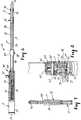
- FIG. 10a first embodiment of surgical stapling instrument according to the present invention, generally designated by the reference numeral 10.
- the surgical stapling instrument 10comprises an anvil frame 12 having proximal 14 and distal 16 ends and a pair of lateral side portions 17 and 18 that are each elongate in a longitudinal direction and spaced to define a channel therebetween.
- the anvil frame 12has a handle portion 19 generally adjacent the proximal end 14 with first 20 and second 21 ends, and a jaw portion 22 having anvil surfaces 23 generally adjacent the distal end 16.
- the anvil surfaces 23are specially shaped and are positioned in a plane generally perpendicular to the longitudinal direction.
- the jaw portion 22includes surfaces defining an alignment aperture 15 opening onto the anvil surfaces 23, the function of which will be described later.
- a handle housing 24is attached to the anvil frame 12 and may be constructed from any suitable material such as but not limited to a polymeric material such as nylon, polypropylene, high density polyethylene, acrylonitrile butadiene styrene (ABS), polyetherimide, polystyrene, acetal or polycarbonate.
- a polymeric materialsuch as nylon, polypropylene, high density polyethylene, acrylonitrile butadiene styrene (ABS), polyetherimide, polystyrene, acetal or polycarbonate.
- An elongate manually movable handle or lever part 25(see Figure 9) having first 26 and second 27 ends is pivotally mounted at its second end 27 to the anvil frame 12 by means such as a pin 28.
- a handle cover 29is attached to the lever part 25 and may be constructed from any suitable material such as but not limited to a polymeric material similar to the material used to construct the handle housing 24.
- the handle cover 29 and the handle housing 24are shaped to afford convenient, efficient manual grasping of the stapler 10 and may be snap fit to the stapler 10 (e.g. the lever part 25 and anvil frame 12 respectively).
- the lever part 25is connected to the anvil frame 12 at a position generally adjacent the second end 21 of the handle portion 19.
- the pin 28mounts the handle part 25 and handle cover 29 to the anvil frame 12 to afford pivotal movement of the lever part 25 relative to the anvil frame 12 between a release position ( Figures 1, 2 and 4) with the first end 26 of the lover part 25 spaced from the first end 14 of the handle portion 19 and an actuation position ( Figures 3 and 5) with the lever part 25 and the handle portion 19 in closely spaced relationship.
- a biasing meansbiases the lever part 25 toward the release position.
- the biasing meanscomprises an extension coil spring 30 mounted at one end to the anvil frame 12 and at the other end to the lever part 25.
- a cartridge assembly 32 having proximal 33 and distal 34 endsis mounted in the channel between the lateral side portions 17 and 18 for longitudinal movement relative to the anvil frame 12.
- the cartridge assembly 32comprises a cartridge transporting member 35 having first 36 and second 37 side portions that are each elongate in the longitudinal direction and that are spaced to define a ram channel therebetween.
- the first and second side portions 36 and 37have surfaces defining a cartridge groove 38 generally adjacent the distal end 34 of the cartridge assembly 32.
- the cartridge groove surfaces 38are adapted to releasably receive a cartridge housing 40.
- the cartridge housing 40includes a plurality of staples 41 disposed in rows oriented in planes generally perpendicular to the longitudinal direction and positioned in opposition to the anvil surfaces 23, and manually activatable means, such as a pusher 42, for pressing the staples 41 within longitudinal slots 46 in the cartridge housing 40 against specially shaped anvil surfaces 23 to engage and close the staples 41 in tissue between the cartridge housing 40 and the anvil surfaces 23.
- the pusher 42has a pair of edges 43 and is positioned proximate the staples 41 for movement between pre-fired ( Figure 12) and fired (Figure 13) positions with the pusher 42 adapted to move distally relative to the cartridge housing 40 when the stapler 10 is fired.
- the cartridge housing 40also has surfaces defining a close fitting hole or alignment through passage 58 positioned in opposition to the alignment aperture 15 in the anvil frame 12.
- the alignment through passage 58 and the alignment aperture 15may be generally cylindrical and coaxial and perform a function to be described later.
- a means such as pins 44 and grooves 45mounts the cartridge assembly 32 for longitudinal movement relative to the anvil frame 12 between a closed position ( Figures 3, 4 and 5) with the cartridge housing 40 and the anvil surfaces 23 in closely spaced relationship, and an open position ( Figures 1 and 2) with the cartridge housing 40 and the anvil surfaces 23 spaced farther from each other than in the closed position.
- An elongate T-bar or ram 48is mounted in the ram channel between the first and second side portions 36 and 37 of the cartridge transport member 35 for longitudinal movement relative to the cartridge transporting member 35 and the anvil frame 12.
- the T-bar or ram 48is adapted to engage the pusher 42 to drive the pusher 42 distally to eject the staples 41 from the cartridge housing 40, to press the staples 41 against the specially shaped anvil surfaces 23 and to engage and close the staples 41 in tissues between the cartridge housing 40 and the anvil jaw portion 22 when the cartridge housing 40 and the anvil surfaces 23 are in the closed position.
- FIGS 2 through 5sequentially illustrate the operation of the stapler 10.
- the actuation means 50is operable in a second movement ( Figures 4 and 5) of the lever part 25 from the release to the actuation position to subsequently fire the stapler 10 (e.g. the actuation means 50 drives the ram 48 distally relative to the cartridge transporting member 35 to engage and move the pusher 42 distally to eject the staples 41 from the cartridge housing 40, to press the staples 41 against the anvil surfaces 23 and to engage and close the staples 41 in tissues between the cartridge housing 40 and the anvil jaw portion 22).
- a meanssuch as a coil spring 51 connected between the anvil frame 12 and the ram 48 bias the cartridge assembly 32 from the closed to the open position and is temporarily overcome by the actuation means 50.
- the actuation means 50preferably comprises a toggle joint linkage 52 having an over center pivoting portion 53 and first 54 and second 55 ends with the first end 54 pivotally mounted to the anvil frame 12 by pin 56 and with the second end 55 pivotally connected to the cartridge transporting member 35 by a pin 57.
- the over center pivoting portion 53preferably has surfaces adapted to engage cooperable surfaces on the lever part 25 when the lever part 25 is first moved from the release to the actuation position to move the toggle joint linkage 52 from a retracted position (see Figures 1 and 2 with the cartridge assembly 32 in the open position) past an in-line or centered position with the toggle joint linkage generally straight, to an extended position ( Figures 3, 4, 5 and 10) with the toggle joint linkage 52 being slightly bent in a direction inverted relative to the retracted position. Movement of the toggle joint linkage 52 from the retracted to the extended position drives the cartridge assembly 32 from the open to the closed positions.
- the actuation meansalso preferably includes means for retaining the cartridge assembly 32 in the closed position against the bias of the coil spring 51 for biasing the cartridge assembly 32 from the closed to the open position.
- a meanscomprises a stop flange 66 on the over center pivoting portion 53 of the toggle joint linkage 52.
- the stop flange 66is adapted to engage surfaces on the toggle joint linkage 52 to prevent the toggle joint linkage 52 from moving past the extended position.
- a meansmay comprise a stop surface located on the handle housing 24.
- a relatively weak torsion spring(not shown) may be mounted on the over center pivoting portion 53 of the toggle joint linkage 52 to bias the toggle joint linkage 52 toward the extended position and to prevent the cartridge assembly from accidentally opening when the handle lever 15 is moved from the actuation to the release position just after firing the stapler 10.
- the actuation means 50preferably includes surfaces defining a cam shoulder surface 49 on the ram 48, and a pawl 60 having first 61 and second 62 ends and a cam surface 63 generally adjacent the second end 62.
- a means such as pin 64mounts the pawl 60 on the lever part 25 for movement between a first position ( Figures 2, 3 and 9) with the cam surface 63 spaced from the cam shoulder surface 49 on the ram 48 and a second position ( Figures 4, 10 and 11) with the cam surface 63 engaged with the cam shoulder surface 49 on the ram 48 to afford firing of the stapler 10 by driving the ram 48 distally relative to the cartridge transporting member 35 when the cartridge assembly 32 is in the closed position.
- the stapler 10further includes means for biasing the pawl toward the second position such as torsion spring 65, and the ram 48 has sliding surfaces 47 adapted to retain the pawl 60 in the first position until the cartridge assembly 32 is moved from the open to the closed position.
- the stapler 10includes a release arm 70 having a first end pivotally mounted to the proximal end 14 of the anvil frame 12 by pin 56 and a second end connected to manually activatable release button 72 extending laterally from the handle housing 24.
- the release arm 70has surfaces 73 adapted to engage shoulder portions or "pin" 67 of the pawl 60 and laterally inwardly projecting surfaces (not shown) adapted to engage the over center portion 53 of the toggle joint linkage 52 to initially move the pawl 60 from the second toward the first position and to then move the toggle joint linkage 52 from the extended toward the retracted position to afford movement of the cartridge assembly 32 from the closed to the open position under the bias of spring 51.
- a safety guide member 88comprising a sleeve 89 having proximal and distal ends.
- the sleeve 89is slidably mounted on the anvil frame 12 for longitudinal movement relative thereto.
- a longitudinally extending alignment or retention pin 90is mounted on the distal end of the sleeve 89 for movement between an alignment position ( Figures 3, 4 and 5) with the alignment pin 90 passing through the cartridge housing alignment through passage 58 and extending into the alignment aperture 15 to position the rows of staples 41 relative to the specially shaped surfaces 23 on the anvil frame 12 to afford a more precisely controlled formation of fired staples and to prevent tissue from escaping from between the cartridge housing 40 and the anvil surfaces 23 when the cartridge assembly 32 is moved to the closed position, and a release position ( Figures 1 and 2) with the alignment pin 90 spaced from the alignment through passage 58 and the alignment aperture 15 to afford removal and replacement of the cartridge housing with a new cartridge housing.
- the alignment pin 90is adapted to position the rows of staples 41 relative to the specially shaped surfaces 23 on the anvil frame 12 to afford a more precisely controlled formation of fired staples and to prevent tissue from escaping from between the cartridge housing 40 and the anvil surfaces 23 when the cartridge assembly 32 is moved to the closed position.
- means 94for preventing the cartridge assembly 32 from moving from the open to the closed position unless the alignment pin 90 is in the alignment position, and for preventing the alignment pin 90 from moving from the alignment position toward the release position when the cartridge assembly 32 is in the closed position comprising surfaces defining a safety notch 92 in the cartridge assembly 32 (including both the ram 48 and the cartridge transport member 35) and the anvil frame 12.
- the means 94includes a safety gate 95 ( Figures 18 and 19) having cam shoulder surfaces 85 and return cam surfaces 8 generally opposite the cam surfaces 85.
- the safety gate 95includes surfaces defining a safety gate hole 87.
- the safety gate 95is mounted adjacent the anvil frame 12 for relative movement thereto between a latched position ( Figure 2) with the safety gate 95 engaged with the surfaces defining the continuous safety notch 92 to prevent relative movement between the cartridge assembly 32 and the anvil frame 12 when the cartridge assembly 32 is in the open position, and an unlatched position ( Figures 3, 4 and 9) with the safety gate 95 spaced from the safety notch 92 to afford relative longitudinal movement of the cartridge assembly 32 and the anvil frame 12 between the open and closed positions.
- the handle housing 24includes guide surfaces defining a slot 77 that affords reciprocating movement of the safety gate 95 between the latched and unlatched positions.
- the safety guide member 88includes safety gate deactivating guides 98 projecting proximally from the proximal end of the sleeve 89 and through the safety gate hole 87. Return cam surfaces 8 of the guides 98 bias the safety gate 95 toward the latched position when the alignment pin 90 is in a position other than the alignment position.
- the cam surfaces 99 at a proximal end of the guides 98are adapted to engage the cam shoulder surfaces 85 of the safety gate 95 to drive the safety gate 95 from the latched to the unlatched position when the alignment pin 90 is moved to the alignment position.
- the stapler 10also includes a means preventing the cartridge assembly from moving from the open to the closed position unless the stapler 10 is loaded with a ready-to-fire staple cartridge.
- a first embodiment of a stapler 10may comprise a means for preventing the cartridge assembly 32 from moving from the open to the closed position when the stapler 10 is loaded with a cartridge housing 40 having a pusher 42 in a fired position.
- a means for preventing the cartridge assembly 32 from moving from the open to the closed position when the stapler 10 is loaded with a cartridge housing 40 having a pusher 42 in a fired positionprevents approximation and clamping of living tissue between anvil (e.g. 23) and cartridge (e.g. 40) components of the stapler 10 when the stapler 10 is loaded with a spent stapler cartridge, and prevents firing of the stapler 10 when the stapler is loaded with a spent stapler cartridge.
- Figures 12 through 14illustrate a stapler 10 wherein the means for preventing the cartridge assembly 32 from moving from the open to the closed position comprises the anvil frame 12 having surfaces defining a safety aperture 81 opening into the surface of the anvil frame 12 and having a bottom surface, and a locking plate or pin 82 having first 83 and second 84 ends.
- the locking pin 82is mounted within the safety aperture 81 for movement between a free travel position ( Figure 12) with the first end 83 of the locking pin 82 generally abutting an edge 43 of the pusher 42 to afford a single, reciprocating movement of the cartridge assembly 32 between the open and closed positions, and a blocking position ( Figure 13) with the first end 83 of the locking pin 82 projecting beyond the safety aperture 81 and into the path of the ram 48 to prevent movement of the cartridge assembly 32 from the open to the closed position.
- a biasing meansbiases the locking pin 82 toward the blocking position. That biasing means preferably comprises a coil spring 86 having a first end connected to the second end 84 of the locking pin 82 and a second end connected to the bottom surf ace of the safety aperture 81.
- Figure 2illustrates the relative positions of the anvil frame 12 and the cartridge assembly 32 in an open position.
- the stapler 10may be positioned adjacent the tissue to be stapled, and the alignment pin 90 is then moved from the release position ( Figure 2) to the alignment position ( Figures 3, 4 and 5) by moving the sleeve 89 distally.
- the cam surfaces 99move the safety gate 95 to the unlatched position to afford relative movement between the cartridge assembly 32 and the anvil frame 12.
- the alignment pin 90passes through the cartridge housing alignment through passage 58 and extends into the alignment aperture 15 to orient and position the rows of staples 41 relative to the specially shaped surfaces 23 on the anvil frame 12 to afford a more precisely controlled formation of fired staples. Placing the alignment pin 90 in the alignment position also prevents tissue from escaping from between the cartridge housing 40 and the anvil surfaces 23 when the cartridge assembly 32 is moved to the closed position.
- Figure 3illustrates the positions of the anvil frame 12 and the cartridge assembly 32 just after the cartridge assembly 32 is moved to the closed position by a first movement of the lever part 25 from the release position to the actuation position, after which the coil spring 30 returns the lever part 25 to the release position shown in Figure 4.
- the surfaces 7 ( Figure 18) on the cartridge transport member 35 and ram 48are adapted to engage the "top" of the safety gate 95 and prevent the return cam surfaces 8 from driving the safety gate 95 from the unlatched position toward the latched position.
- the means 94also prevents the alignment pin 90 from moving from the alignment position toward the release position when the cartridge assembly 32 is in the closed position. This feature prevents a user from (1) clamping the stapler 10 on the tissue to be stapled and (2) thereafter moving the alignment pin 90 from the alignment position.
- Figure 4shows the positions of the anvil frame 12 and the cartridge assembly 32 just before the stapler 10 is fired.
- the pawl 60moves to the second position with the cam surface 63 generally engaged with the cam shoulder surface 49 of the ram 48. In this position, the stapler 10 is ready to be fired.
- a second movement of the lever part 25 from the release position to the actuation position( Figure 5) causes the ram 48 to move distally relative to the cartridge transport member 35 and the anvil frame 12, which drives the pusher 42 distally to eject the staples 41 from the cartridge housing 40 to press the staples 41 against the specially shaped anvil surfaces 23 and to engage and close the staples 41 in tissues between the cartridge housing 40 and the anvil jaw portion 22.
- the spring 51biases the cartridge assembly toward the open position but is prevented from moving the cartridge assembly 32 to the open position by engagement between a stop flange 66 of the toggle joint linkage 52 with another portion of the toggle joint linkage 52 generally adjacent the over center pivoting portion 53.
- engagement between the toggle joint linkage 52 and surfaces on the handle housing 24may prevent further movement of the toggle joint linkage 52.
- a torsion spring(not shown) prevents the toggle joint linkage from accidentally "popping-up" or returning to the retracted position when the stapler 10 is fired.
- the usermay control the return of the cartridge assembly 32 to the open position by moving manually activatable release button 72 "upward” to engage surfaces 73 of release arm 70 with shoulder portions or pin 67 of the pawl 60 and to engage laterally inwardly projecting surfaces (not shown) on the arm 70 with the over center portion 53 of the toggle joint linkage 52 to move the pawl 60 from the second toward the first position and to move the toggle Joint linkage 52 from the extended toward the retracted position against the bias of the torsion spring (not shown).
- Such a movement of the release arm 70allows the spring 51 to return the cartridge assembly 32 to the open position.
- the pusher 42is located closer to the cartridge housing 40 than in the pre-fired position so that the second end of pin 82 no longer engages the edge 43 of pusher 42.
- the spring 86biases the pin 82 from the free-travel to the blocking position with the first end 83 of the locking pin 82 projecting beyond the safety aperture 81 and into the path of the ram 48 to thereby prevent movement of the cartridge assembly 32 from the open to the closed position.
- the pin 82will not only prevent the stapler 10 from firing when loaded with a spent cartridge, but will also prevent the firing of the stapler 10 when the stapler is not loaded with a cartridge housing 40 at all.
- the pin 82prevents firing of the stapler 10 should the fired cartridge housing be replaced with another fired cartridge, since the edge portion of the pusher of the fired cartridge would not be able to move the pin 82 from the blocking to the free-travel position.
- the stapler 10can be refired only by replacing the fired cartridge housing with an unfired or ready-to-fire cartridge housing 40 having an edge surface 43 of the pusher 42 in the proper position to move the pin 82 to the free-travel position.
- the mechanical advantage provided by the toggle joint linkage 52is at its minimum when the cartridge assembly 32 is in the open position and generally increases as the cartridge assembly 32 moves toward the closed position. Thus, it is important to prevent the cartridge assembly 32 from moving from the open toward the closed position to thereby minimize the shear force transmitted through the toggle joint linkage 52 to the pin 82.
- FIGS 15 through 17illustrate a second embodiment of surgical stapler generally designated by the reference character 100 which has many parts that are essentially the same as the parts of the stapler 10 and which have been identified by the same reference numeral to which the suffix "A" has been added.
- the stapler 100includes comprises an anvil frame 12A having proximal and distal 16A ends and a pair of lateral side portions 17A and 18A that are each elongate in a longitudinal direction and spaced to define a channel therebetween.
- the anvil frame 12Ahas a handle portion (not shown but generally identical to the handle 19 of stapler 10) generally adjacent the proximal end with first and second ends, and a jaw portion 22A having specially shaped anvil surfaces 23A generally adjacent the distal end 16A.
- the anvil surfaces 23Aare positioned in a plane generally perpendicular to the longitudinal direction.
- the jaw portion 22Aincludes surfaces defining an alignment aperture 15A opening onto the anvil surfaces 23A.
- the stapler 100includes a cartridge assembly 32A having proximal and distal 34A ends that is mounted in the channel between the lateral side portions 17A and 18A for longitudinal movement relative to the anvil frame 12A.
- the cartridge assembly 32Acomprises a cartridge transporting member 35A having first and second side portions that are each elongate in the longitudinal direction and that are spaced to define a ram channel therebetween.
- the first and second side portionshave surfaces defining a cartridge groove 38A generally adjacent the distal end 34A of the cartridge assembly 32A.
- the cartridge groove surfaces 38Aare adapted to releasably receive a cartridge housing 40A.
- the cartridge housing 40Aincludes a plurality of staples 41A disposed in rows oriented in planes generally perpendicular to the longitudinal direction and positioned in opposition to the anvil surfaces 23A, and manually activatable means, such as a pusher 42A, for pressing the staples 41A within longitudinal slots in the cartridge housing 40A against the specially shaped anvil surfaces 23A to engage and close the staples 41A in tissue between the cartridge housing 40A and the anvil surfaces 23A.
- the pusher 42Ahas a pair of edges 43A and is positioned proximate the staples 41A for movement between pre-fired (Figure 15) and fired ( Figure 16) positions with the pusher 42A adapted to move distally relative to the cartridge assembly 32A when the stapler 100 is fired.
- the cartridge housing 40Aalso has surfaces defining a close fitting hole or alignment through passage positioned in opposition to the alignment aperture 15A in the anvil frame 12A.
- the alignment through passage and the alignment aperture 15Amay be generally cylindrical and coaxial.
- An elongate T-bar or ram 48Ais mounted in the ram channel between the first and second side portions of the cartridge transport member 35A for longitudinal movement relative to the cartridge transporting member 35A and the anvil frame 12A.
- the T-bar or ram 48Ais adapted to drive the pusher 42A distally to eject the staples 41A from the cartridge housing 40A to press the staples 41A against the specially shaped anvil surfaces 23A and to engage and close the staples 41A in tissues between the cartridge housing 40A and the anvil jaw portion 22A when the cartridge housing 40A the anvil surfaces 23A are in the closed position.
- the stapler 100includes a different means 102 for preventing the cartridge assembly 32A from moving from the open to the closed position when the stapler 100 is loaded with a cartridge housing 40A with the pusher 42A in a fired position.
- the means 102prevents approximation and clamping of living tissue between anvil (e.g. 23A) and cartridge (e.g. 40A) components of the stapler 100 when the stapler 100 is loaded with a spent stapler cartridge, and prevents firing of the stapler 100 when the stapler 100 is loaded with a spent stapler cartridge.
- the means 102comprises the anvil frame 12A having surfaces defining a safety aperture 103 opening into the surface of the anvil frame 12A and having a bottom surface, a locking notch 110 in the cartridge transport member 35A of the cartridge assembly 32A, and a locking plate or pin 104 having first 105 and second 106 ends.
- the locking pin 104is mounted within the safety aperture 103 for movement between a free travel position ( Figure 15) with the first end 105 of the locking pin 104 generally abutting an edge 43A of the pusher 42A and spaced from the locking notch 110 to afford a single, reciprocating movement of the cartridge assembly 32A between the open and closed positions, and a blocking position ( Figure 16) with the first end 105 of the locking pin 104 projecting beyond the safety aperture 103 and engaged with the surfaces of the locking notch 110 to prevent movement of the cartridge assembly 32A from the open to the closed position.
- Biasing meanssuch as a coil spring 109 having a first end connected to the second end 106 of the locking pin 104 and a second end connected to the bottom surface of the safety aperture 103, biases the locking pin 104 toward the blocking position.
- FIGS 20 and 21illustrate a third embodiment of surgical stapler according to the present invention generally designated by the reference character 200 which has many parts that are essentially the same as the parts of the stapler 100 and which have been identified by the same reference numeral to which the suffix "B" has been added.
- the stapler 200includes comprises an anvil frame 12B which is elongate in a longitudinal direction.
- the anvil frame 12Bhas a handle portion (not shown but generally identical to the handle 19 of stapler 10), and a jaw portion 22B having specially shaped anvil surfaces (not shown but generally identical to the anvil surfaces 23 and 23A).
- the anvil surfacesare positioned in a plane generally perpendicular to the longitudinal direction.
- the jaw portion 22Bincludes surfaces defining an alignment aperture opening onto the anvil surfaces.
- the stapler 200includes a cartridge assembly 32B that is mounted for longitudinal movement relative to the anvil frame 12B.
- the cartridge assembly 32Bcomprises a cartridge transporting member 35B surfaces defining a cartridge groove generally adjacent a distal end of the cartridge assembly 32B.
- the cartridge groove surfacesare adapted to releasably receive a cartridge housing (not shown but generally identical to the cartridge housings 40 and 40A).
- the cartridge housingincludes a plurality of staples (not shown but generally identical to the staples 41 and 41) disposed in rows oriented in planes generally perpendicular to the longitudinal direction and positioned in opposition to the anvil surfaces and manually activatable means, such as a pusher 42B, for pressing the staples within longitudinal slots in the cartridge housing against the specially shaped anvil surfaces to engage and close the staples in tissue between the cartridge housing and the anvil surfaces.
- a pusher 42Bmanually activatable means
- the pusher 42Ahas a pair of edges 43B and is positioned proximate the staples for movement between pre-fired ( Figure 20) and fired ( Figure 21) positions with the pusher 42B adapted to move distally relative to the cartridge assembly 32B when the stapler 200 is fired.
- the cartridge housingalso has surfaces defining a close fitting hole or alignment through passage positioned in opposition to an alignment aperture in the anvil frame 12B.
- the alignment through passage and the alignment aperturemay be generally cylindrical and coaxial.
- An elongate T-bar or ram 48Bis mounted in the ram channel between the first and second side portions of the cartridge transport member for longitudinal movement relative to the cartridge transporting member and the anvil frame 12B.
- the T-bar or ram 48Bis adapted to drive the pusher 42B distally to eject the staples from the cartridge housing to press the staples against the specially shaped anvil surfaces and to engage and close the staples in tissues between the cartridge housing and the anvil jaw portion 22B when the cartridge housing the anvil surfaces are in the closed position.
- the stapler 200includes a different means 202 for preventing the cartridge assembly 32B from moving from the open to the closed position unless the stapler 200 is loaded with a ready-to-fire cartridge housing.
- the means 202prevents approximation and clamping of living tissue between anvil and cartridge components of the stapler 200 when the stapler 200 is unloaded or loaded with a spent stapler cartridge, and prevents firing of the stapler 200 when the stapler 200 is unloaded or loaded with a spent stapler cartridge.
- the means 202comprises the anvil frame 12B having surfaces defining a safety aperture 103B opening into the surface of the anvil frame 12B and having a bottom surface.
- the means 202includes a locking notch 210 in the cartridge transport member of the cartridge assembly 32B having sloped surfaces 220, and a locking plate or pin 204 having first 205 and second 206 ends with a ramped camming surface 230 generally adjacent the first end 205.
- the locking pin 204is mounted within the safety aperture 103B for movement between a free travel position ( Figure 20) with the first end 205 of the locking pin 204 generally abutting an edge of the pusher 42B and spaced from the locking notch 210 to afford a single, reciprocating movement of the cartridge assembly 32B between the open and closed positions, and a blocking position ( Figure 16) with the first end 205 of the locking pin 204 projecting beyond the safety aperture 103B and engaged with the surfaces of the locking notch 210 to prevent movement of the cartridge assembly 32B from the open to the closed position.
- Biasing meanssuch as a coil spring 109B having a first end connected to the second end 206 of the locking pin 204 and a second end connected to the bottom surface of the safety aperture 103B biases the locking pin 204 toward the blocking position.
- either the locking notch 210 and/or the locking pin 204may have sloped or ramped camming surfaces to cam the locking pin 204 to the free travel position when the cartridge assembly initially moves from the open to the closed position, but which does not cam the locking pin 204 to the free-travel position when the stapler is unloaded or when the stapler is loaded with a staple cartridge other than a ready-to-fire staple cartridge.
- the means 202is believed to provide a mechanism which is easier to construct than the means 102 as the sloped surfaces 220 and the ramped camming surface 230 are believed to be less sensitive to individual part differences or tolerances, in for example, the relative positions of the cartridge housing 40B, the cartridge transport member 35B and the edge 43B of the pusher 42B.
- the pin 82 and the spring 86may be replaced with a plastic part with an integrally molded spring.
- the pin 104may be adapted to engage a slot (not shown) in the cartridge housing 40A rather than the locking notch 110 in the cartridge assembly 32.
- the means 94could be completely eliminated from the stapler 10 according to the present invention, and the anvil frame 12 and the cartridge assembly 32 may be constructed from any suitable material such as but not limited to a metal or plastic material.
- the locking plate or pins 82, 104, 204may be constructed from any suitable, tough material such as metal or plastic and may have arcuate portions (not shown) adjacent their ends which are adapted to engage the edge (e.g. 43B) of the pusher. The arcuate edges cam the pins toward the free travel position when the stapler is loaded with an unfired cartridge and the cartridge assembly initially moves toward the closed position.
- the scope of the present inventionshould not be limited to the structure described in this application, but only by structures described by the language of the claims and the equivalents of those structures.
Landscapes
- Health & Medical Sciences (AREA)
- Life Sciences & Earth Sciences (AREA)
- Surgery (AREA)
- Heart & Thoracic Surgery (AREA)
- Engineering & Computer Science (AREA)
- Biomedical Technology (AREA)
- Nuclear Medicine, Radiotherapy & Molecular Imaging (AREA)
- Medical Informatics (AREA)
- Molecular Biology (AREA)
- Animal Behavior & Ethology (AREA)
- General Health & Medical Sciences (AREA)
- Public Health (AREA)
- Veterinary Medicine (AREA)
- Surgical Instruments (AREA)
Abstract

Description
- The present invention relates generally to surgical stapling instruments and more particularly to the type of surgical stapling instruments used for applying linear parallel rows of staggered staples through compressed living tissue.
- Surgical stapling instruments used for applying parallel rows of staples through compressed living tissue are well known in the art, and are commonly used for closure of tissue or organs prior to transection, prior to resection, or in anastomoses, and for occlusion of organs in thoracic and abdominal plasty procedures.
- One known pneumo-intestinal surgical stapling instrument of this type has been in use for many years, and is currently available under the trade designation "The PI Stapler", catalog # 3960 by minnesota Mining and Manufacturing Company (3M), St. Paul, Minnesota, the use of which stapler is described in a publication entitled "Surgical Stapling, Gastric and Small Bowel Procedures, Volume I". ISBN 0-937433-00-4, Library of Congress Catalog Number 85-082599 available from Minnesota Mining and Manufacturing Company (3M), St. Paul, Minnesota. That stapler and a similar stapler described in Freund et al. PCT Application No. WO 83/02247, published July 7, 1983 are adapted for firing staples into compressed living tissue from a staple filled cartridge or housing. The staplers have anvil and jaw portions, a cartridge holder including a removable cartridge and a handle lever.
- "PI" type staplers have a handle lever, a generally C-shaped anvil portion having free and supported ends with an alignment aperture generally adjacent its free end, a cartridge transport member adapted to releasably receive a cartridge or staple housing having an alignment through passage, and an alignment pin movable between an engaged or alignment position with the alignment pin extending through the through passage in the staple housing and into the alignment aperture in the anvil jaw and a release or disengaged position with the alignment pin spaced from the alignment through passage and alignment aperture to afford removal and replacement of a spent staple cartridge.
- The anvil and cartridge transport members are each elongate in a longitudinal direction, and the anvil portion has specially shaped anvil surfaces situated in a plane generally perpendicular to the longitudinal direction. When the alignment pin extends through the through passage in the staple housing and into the alignment aperture in the anvil jaw (i.e. when the alignment pin is in the alignment position), the specially shaped anvil surfaces are positioned generally opposite longitudinal slots in the cartridge or staple housing which contain unfired staples. The cartridge transport member/cartridge housing is movable between a closed or clamping position with the cartridge housing and the anvil surfaces in closely spaced relationship, and an open position with the cartridge housing and the anvil surfaces spaced farther from each other than in the closed position.
- Typically, a "PI" type stapler is positioned adjacent the tissue to be stapled, the anvil and jaw portions are approximated adjacent the tissue to be stapled, the alignment pin is moved to the alignment position, and the stapler is clamped on the tissue by moving the handle lever in a first movement to cause the cartridge holder to move toward the anvil placing the cartridge housing in a closed "clamping" position where the staples may be fired. Moving the handle lever in a second movement "fires" the stapler (e.g. it ejects the staples from the cartridge).
- In some surgical procedures the clamping force results in tissue that is highly compressed to ensure, inter alia, proper hemostasis in the tissues being stapled. The clamping force is present in various degrees in each of the surgical procedures for a "PI" type surgical stapler. Such a clamping force causes tissue trauma in the tissue to be stapled, at least to some degree.
- Under a great clamping force, a prior art "PI" type stapler without an engaged alignment pin typically "scissors" or fails by deflection of the anvil portion and the cartridge housing laterally relative to one another (e.g. where the anvil portion deflects laterally with respect to the longitudinal axis of the stapler and/or where the cartridge housing deflects in a lateral direction opposite the deflection direction of the anvil portion).
- Moving the alignment pin to the alignment position before firing the stapler or before clamping tissue between the anvil and cartridge housing affords a more precisely controlled formation of the fired staples by aligning the specially shaped surfaces on the anvil portions with the staples in the cartridge housing and by preventing the cartridge housing and the specially shaped anvil surfaces from "scissoring". Moving the alignment pin to the alignment position also prevents tissue from escaping from between the anvil and cartridge housing when the cartridge assembly is clamped on the tissue to be stapled.
- The prior art "PI" type staplers encounter problems because it is possible to fire the stapler or clamp tissue between the anvil and cartridge housing without the alignment pin in the alignment position. It is believed that it is difficult to determine whether the alignment pins of the prior art "PI" type staplers are engaged, particularly in the surgical environment. Also, it is possible to inadvertently fail to move the alignment pin to the alignment position. If the alignment pin is not moved to the alignment position before clamping tissue between the anvil and cartridge housing, tissue intended to be stapled may escape from between the anvil and cartridge housing resulting in incomplete anastomoses and other undesirable results. Additionally, if the alignment pin is not moved to the alignment position before the stapler is fired, the staples may be improperly formed.
- The prior art "PI" type staplers also encounter problems because it is difficult to determine when they are loaded with a "spent" cartridge or with a cartridge that does not contain staples. on occasion, a spent cartridge may be inadvertently left in a stapler after it has been fired during a surgical procedure where the stapler is used several times for the same patient, or a spent cartridge may be inadvertently loaded into a stapler that is about to be fired in the patient. If a stapler is loaded with a cartridge housing other than a ready-to-fire cartridge housing and the stapler is clamped on tissue to be stapled, the compressive forces created by the stapler subject the tissue to undesirable and unnecessary trauma. The sequence of (1) clamping the stapler with a spent cartridge on tissue, (2) firing the "dud" stapler (3) subsequently rearming, (4) again approximating the stapler adjacent the tissue to be stapled and (5) reclamping the stapler wastes precious time during the surgical procedure.
- Additionally, the prior art "PI" type staplers may be used in procedures in which the surgeon uses a scalpel to manually create an incision on a side of closed staples (e.g. the procedure described in the article entitled "Resection of the Lesion" on
pages 14 and 15 of the publication entitled "Surgical Stapling, Gastric and Small Bowel Procedures, Volume I", ISBN 0-937433-00-4, Library of Congreas Catalog Number 85-082599 available from Minnesota Mining and Manufacturing Company (3M), St. Paul, Minnesota). A spent stapler cartridge used in such procedures may result in unnecessary blood loss, inadequate hemostasis and tissue trauma for the patient undergoing the procedure. - Surgical stapler cartridge safety devices are described in U.S. Patents No. 4,863,088 and 4,955,959, and U.S. Patent Application 07/629,597. The firing mechanisms in those staplers sequentially close staples into tissue. Since each staple is closed within tissue one after another in succession, the force required to fire such staplers is generally less than the force required to fire a "PI" type stapler where all the staples are generally closed in tissue at the same time.
- Unlike the present invention wherein the same part (e.g. a lever or "handle") is operable in both a first movement to approximate and clamp tissue and a second movement to close all the staples within tissue generally simultaneously, the "ILA" type staplers described in U.S. Patents No. 4,863,088 and 4,955,959, and U.S. Patent Application 07/629,597 utilize separate and distinct member to (1) sequentially fire the staples (e.g. a firing tab or button) and (2) clamp onto the tissue (an element of the stapler that does not include the firing tab or button).
- U.S. Patent No. 4,527,724 to Chow et al. and assigned to Senmed, Inc., of Cincinnati, Ohio discloses a surgical stapler similar to the surgical stapler sold by Ethicon, Inc., of Somerville, N.J. under the trade name "Proximate". That stapler includes a lockout device which precludes rotation of an adjustment knob to clamp the stapler on tissue unless the alignment and retaining pin is shifted to its operative position. The lockout device, however, is only operative until the user slides the alignment and retaining pin to the operative position. Once the user slides the alignment and retaining pin to the operative position, the lockout device is not designed to be easily reactivated. Thus, to defeat the lockout device, a user need only slide the pin to the operative position and then away from the operative position. The stapler has no feature which retains the pin in the operative position when the stapler is clamped on tissue.
- The present invention provides a surgical stapler comprising an anvil frame elongate in a longitudinal direction and including anvil surfaces in a plane generally perpendicular to the longitudinal direction, surfaces defining an alignment aperture opening onto the anvil surf aces, and a cartridge assembly movable relative to the anvil frame between an open position with the cartridge assembly spaced from the anvil surfaces and a closed position with the cartridge assembly and the anvil surfaces in closely spaced relationship. The cartridge assembly comprises a cartridge housing containing a plurality of staples disposed in rows positioned in opposition to the anvil surfaces.
- The surgical stapler also includes a longitudinally extending alignment pin mounted on the stapler for movement between an alignment position with the alignment pin extending into the alignment aperture, and a release position with the alignment pin spaced from the alignment aperture.
- By including a mechanism for engaging the cartridge assembly and anvil for continuously preventing the cartridge assembly from moving from the open to the closed position whenever the alignment pin is in a position other than the alignment position, and for preventing the alignment pin from moving from the alignment position toward the release position when the cartridge assembly is in the closed position, the present invention provides a stapler which (1) contributes to the proper formation of staples, (2) promotes proper hemostasis in the tissue to be stapled, (3) prevents "scissoring" of the anvil and cartridge portions of the stapler, (4) prevents tissue from escaping from between the anvil and cartridge housing when the cartridge assembly is clamped on the tissue to be stapled, and (5) reduces the likelihood of a weak joint or an absence of blood flow in the joint and tissue.
- The stapler according to the invention includes a mechanism for firing the stapler by engaging and closing the staples in tissue between the cartridge housing and the anvil surfaces, and a means preventing the cartridge assembly from moving from the open to the closed position unless the stapler is loaded with a ready-to-fire cartridge housing. The means for preventing the cartridge assembly from moving from the open to the closed position (1) prevents approximation and clamping of living tissue between anvil and cartridge components of the stapler when the stapler is loaded with a spent stapler cartridge, (2) prevents the user from attempting to refire the stapler, and (3) provides a stapler that reduces the chances of unnecessary tissue trauma, blood loss, inadequate hemostasis, and squandered time during surgery.
- According to a preferred embodiment of the stapler of the present invention, there is provided a stapling instrument comprising an anvil frame having proximal and distal ends and a pair of lateral side portions that are each elongate in a longitudinal direction and spaced to define a channel therebetween. The anvil frame has a handle portion generally adjacent the proximal end with first and second ends, and a jaw portion having anvil surfaces generally adjacent the distal end. The jaw portion includes surfaces defining an alignment aperture opening onto the anvil surfaces, and the anvil surfaces are positioned in a plane generally perpendicular to the longitudinal direction.
- An elongate manually movable handle or lever part having first and second ends is pivotally mounted at its second end to afford pivotal movement of the lever part relative to the anvil frame between a release position with the first end of the lever part being spaced from the first end of the handle portion and an actuation position with the lever part and the handle portion in closely spaced relationship. A biasing means (such as a coil spring mounted at one end to the anvil frame and at the other end to the lever part) biases the lever part toward the release position. Preferably the biasing means comprises a coil spring mounted at one end to the anvil frame and at the other end to the lever part.
- A cartridge assembly having proximal and distal ends is mounted in the channel between the lateral side portions for longitudinal movement relative to the anvil frame. The cartridge assembly comprises a cartridge transporting member having first and second side portions that are each elongate in the longitudinal direction and that are spaced to define a ram channel therebetween. The first and second side portions have surfaces defining a cartridge groove generally adjacent the distal end of the cartridge assembly.
- The cartridge groove surfaces are adapted to releasably receive a cartridge housing containing a plurality of staples disposed in rows positioned in opposition to the anvil surfaces, and pusher means, such as a pusher, for pressing the staples within the cartridge housing against the anvil surfaces to engage and close the staples in tissue between the cartridge housing and the anvil surfaces. The pusher has a pair of edges and is positioned proximate the staples for movement between pre-fired and fired positions with the pusher adapted to move distally relative to the cartridge housing when the stapler is fired. The cartridge housing also includes surfaces defining an alignment through passage positioned in opposition to the alignment aperture and whose function will be described later.
- A means mounts the cartridge assembly for longitudinal movement relative to the anvil frame between a closed position with the cartridge housing and the anvil surfaces in closely spaced relationship, and an open position with the cartridge housing and the anvil surfaces spaced farther from each other than in the closed position.
- An elongate T-bar or "ram" is mounted in the ram channel between the first and second side portions for longitudinal movement relative to the cartridge transporting member and the anvil frame. The ram is adapted to engage and drive the pusher distally to fire the stapler when the cartridge housing the anvil surfaces are in the closed position.
- An actuation means is present to initially move the cartridge assembly from the open to the closed position by a first movement of the lever part from the release to the actuation position and for subsequently firing the stapler (i. e. moving the ram distally relative to the cartridge transporting member to cause the pusher to eject the staples from the cartridge housing, to press the staples against the anvil surfaces and to engage and close the staples in tissues between the cartridge housing and the anvil jaw portion) by a second movement of the lever part from the release to the actuation position. Another biasing means (such as a coil spring connected between the anvil frame and the ram) biases the cartridge assembly from the closed to the open position. That biasing means preferably comprises a coil spring connected between the anvil frame and the ram.
- The actuation means preferably comprises a toggle joint linkage having an over center pivoting portion and first and second ends with the first end fixed to the anvil frame and with the second end connected to the cartridge transporting member. The over center pivoting portion preferably has surfaces adapted to engage the lever part when the lever part is first moved from the release to the actuation position to move the toggle joint linkage from a retracted position past an in-line or centered position with the toggle joint linkage generally straight, to a slightly inverted (relative to the retracted position) extended position to drive the cartridge assembly from the open to the closed positions. The actuation means also preferably includes means for retaining the cartridge assembly in the closed position against the bias of the coil spring that biases the cartridge assembly from the closed to the open position. Preferably, such a means comprises a stop flange on the over center pivoting portion of the toggle joint linkage that prevents the toggle joint linkage from moving past the extended position. Alternatively such a means may comprise a stop surface located on a handle cover.
- The actuation means also preferably includes surfaces defining a cam shoulder surface on the ram, and a pawl having first and second ends and a cam surface generally adjacent the second end of the pawl, and means mounting the pawl on the lever part for movement between a first position with the cam surf ace generally spaced from the cam shoulder surface on the ram and a second position with the cam surface engaged with the cam shoulder surface on the ram to afford firing of the stapler by driving the ram distally relative to the cartridge transporting member. Also preferably, the stapler further includes means, such as a torsion spring, for biasing the pawl toward the second position, and the ram has surfaces which are adapted to retain the pawl in the first position until the cartridge assembly is moved from the open to the closed position.
- Additionally, the stapler preferably further includes a release arm having a first end pivotally mounted to the proximal end of the anvil frame and a second engagement end. The release arm has surf aces adapted to engage the pawl and the toggle joint linkage to move the pawl from the second to the first position and to move the toggle joint linkage from the extended toward the retracted position to afford movement of the cartridge assembly from the closed to the open position under the bias of the means for biasing the cartridge assembly from the closed to the open position (e.g. the coil spring).
- The stapler according to the present invention also includes a means for sensing whether the stapler is loaded with a fired cartridge housing and for preventing the stapler from being closed or fired when loaded with the fired cartridge.
- In a first embodiment of a stapler according to the present invention, the means for preventing the cartridge assembly from moving from the open to the closed position when the stapler is loaded with a spent cartridge housing comprises the anvil frame having surfaces defining a safety aperture opening into the surface of the anvil frame and having a bottom surface, and a locking pin having first and second ends. The locking pin is mounted within the safety aperture for movement between a free travel position with the first end of the locking pin abutting an edge of the pusher to afford a single, reciprocating movement of the cartridge assembly between the open and closed positions, and a blocking position with the first end of the locking pin projecting beyond the safety aperture and into the path of the ram to prevent subsequent movement of the cartridge assembly from the open to the closed position. A biasing means biases the locking pin toward the blocking position. That biasing means preferably comprises a coil spring having a first end connected to the second end of the locking pin and a second end connected to the bottom surface of the safety aperture.
- In a second embodiment of stapler according to the present invention, the stapler includes a different means for preventing the cartridge assembly from moving from the open to the closed position when the stapler is loaded with a cartridge housing with the pusher in a fired position comprising a locking notch in the cartridge transport member of the cartridge assembly such that the locking pin engages with the surfaces of the locking notch to prevent movement of the cartridge assembly from the open to the closed position when the locking pin is in the blocking position. In the second embodiment, the locking pin engages the locking notch to prevent movement of the cartridge assembly rather than simply acting as an obstacle to the ram.
- In a third embodiment of stapler according to the present invention, the locking notch and/or the locking pin have sloped or ramped camming surfaces to cam the locking pin toward the free travel position when the cartridge assembly initially moves from the open to the closed position.
- The three embodiments mentioned above may also include a safety guide member. The safety guide member comprises (1) a sleeve slidably mounted on the anvil frame for longitudinal movement relative thereto and having proximal and distal ends, (2) a longitudinally extending alignment pin mounted on the distal end of the sleeve for movement between an alignment position with the pin passing through the cartridge housing alignment through passage and extending into the alignment aperture and a release position with the alignment pin spaced from the alignment through passage and the alignment aperture, and (3) means for preventing the cartridge assembly from moving from the open to the closed positions unless the alignment pin is in the alignment position, and for preventing the alignment pin from moving from the alignment position toward the release position when the cartridge assembly is in the closed position.
- The means for preventing the cartridge assembly from moving from the open to the closed positions unless the alignment pin is in the alignment position, and for preventing the alignment pin from moving from the alignment position toward the release position when the cartridge assembly is in the closed position preferably comprises surfaces defining a safety notch in the anvil frame, cartridge transport member and ram, and a safety gate having cam shoulder surfaces and surfaces defining a hole. The surfaces defining a safety notch in the anvil frame, cartridge transport member and ram are aligned when the cartridge assembly is in the open position to define a continuous safety notch extending laterally across the stapler and are staggered when the cartridge assembly is in the closed position.
- The safety gate is mounted adjacent the anvil frame for relative movement thereto between a latched position with the safety gate engaged with the surfaces defining the continuous safety notch to prevent relative movement between the cartridge assembly and the anvil frame, and an unlatched position with the safety gate spaced from the safety notches to afford relative movement of the cartridge assembly and the anvil frame between the open and closed positions.
- The safety guide member includes safety gate deactivating guides projecting proximally from the proximal end of the sleeve and through the safety gate hole. The guides are adapted to bias the safety gate toward the latched position when the alignment pin is in a position other than the alignment position and have cam surfaces at a proximal end adapted to engage the cam shoulder surfaces of the safety gate to drive the safety gate from the latched to the unlatched position when the alignment pin is moved to the alignment position.
- The means for preventing the alignment pin from moving from the alignment position toward the release position when the cartridge assembly is in the closed position includes the safety gate deactivating guides having return cam surfaces generally opposite the cam surfaces adapted to engage surfaces on the safety gate to drive the safety gate from the unlatched toward the latched position when the alignment pin is moved away from the alignment position, and surfaces on the cartridge transport member and ram adapted to engage the safety gate to prevent the return cam surfaces from driving the safety gate from the unlatched position toward the latched position to thereby prevent the alignment pin from moving from the alignment position toward the release position when the cartridge assembly is in the closed position.
- The present invention will be further described with reference to the accompanying drawing wherein like reference numerals refer to like parts in the several views, and wherein:
- Figure 1 is a perspective view of the surgical stapling instrument according to the present invention;
- Figures 2 through 5 are enlarged first side views of the surgical instrument of Figure 1 which sequentially illustrate the operation of the stapler wherein:
- Figure 2 shows the relative positions of the anvil frame and the cartridge assembly in an open position and has portions broken away to show details;
- Figure 3 illustrates the positions of the anvil frame and the cartridge assembly just after the cartridge assembly is moved to the closed position and has portions broken away to show details;
- Figure 4 shows the positions of the anvil frame and the cartridge assembly just before the stapler is fired and has portions broken away to show details;
- Figure 5 illustrates the stapler just after the stapler is fired;
- Figure 6 is an enlarged bottom view or the surgical instrument of Figure 1 which has portions broken away to show details;
- Figure 7 is an enlarged sectional view of the stapler of Figure 1 taken approximately along line 7-7 of Figure 5;
- Figure 8 is an enlarged sectional view of the stapler of Figure 1 taken approximately along line 8-8 of Figure 2 and having portions broken away to show details;
- Figure 9 is an enlarged second side view of the stapler of Figure 1 having portions broken away to show details of an actuation mechanism;
- Figure 10 is an enlarged second side view of the stapler of Figure 1 having portions broken away to show details of an actuation mechanism and which illustrates the proximal end of the stapler;
- Figure 11 is an enlarged first side view of the stapler of Figure 1 having portions broken away to show details or an actuation mechanism;
- Figure 12 is an enlarged first side view or the distal end of the stapler of Figure 1 illustrating a pusher in a pre-fired position;
- Figure 13 is an enlarged first side view of the distal end of the stapler of Figure 1 illustrating a pusher in a fired position;
- Figure 14 is an enlarged sectional view of the stapler of Figure 13 taken approximately along line 14-14 of Figure 13 and having portions broken away to show details;
- Figure 15 is an enlarged first side view of a distal end of a second embodiment of surgical stapler according to the present invention whose proximal end is generally identical to the proximal end of the stapler of Figure 1, and which illustrates a pusher in a pre-fired position;
- Figure 16 is an enlarged first side view of the distal end of the stapler of Figure 15 illustrating a pusher in a fired position;
- Figure 17 is an enlarged sectional view of the stapler of Figure 15 taken approximately along line 17-17 of Figure 16 and having portions broken away to show details;
- Figure 18 is an enlarged perspective view of the stapler of Figure 1 having portions broken away to show detail and showing a safety gate in a latched position;
- Figure 19 is a sectional view of the stapler of Figure 1 taken approximately along line 19-19 of Figure 9;
- Figure 20 is an enlarged first side view of a distal end of a third embodiment of surgical stapler according to the present invention whose proximal end is generally identical to the proximal end of the stapler of Figure 1, with portions broken away to shown details of a ramped pin and locking notch, illustrating a pusher in a pre-fired position; and
- Figure 21 is an enlarged first side view of the distal end of the stapler of Figure 20 illustrating a pusher in a fired position.
- Referring now to Figures 1 through 14 of the drawing, there is shown a first embodiment of surgical stapling instrument according to the present invention, generally designated by the
reference numeral 10. - Generally the
surgical stapling instrument 10 comprises ananvil frame 12 having proximal 14 and distal 16 ends and a pair oflateral side portions anvil frame 12 has ahandle portion 19 generally adjacent theproximal end 14 with first 20 and second 21 ends, and ajaw portion 22 having anvil surfaces 23 generally adjacent thedistal end 16. The anvil surfaces 23 are specially shaped and are positioned in a plane generally perpendicular to the longitudinal direction. Thejaw portion 22 includes surfaces defining an alignment aperture 15 opening onto the anvil surfaces 23, the function of which will be described later. - A
handle housing 24 is attached to theanvil frame 12 and may be constructed from any suitable material such as but not limited to a polymeric material such as nylon, polypropylene, high density polyethylene, acrylonitrile butadiene styrene (ABS), polyetherimide, polystyrene, acetal or polycarbonate. - An elongate manually movable handle or lever part 25 (see Figure 9) having first 26 and second 27 ends is pivotally mounted at its
second end 27 to theanvil frame 12 by means such as apin 28. Ahandle cover 29 is attached to thelever part 25 and may be constructed from any suitable material such as but not limited to a polymeric material similar to the material used to construct thehandle housing 24. Thehandle cover 29 and thehandle housing 24 are shaped to afford convenient, efficient manual grasping of thestapler 10 and may be snap fit to the stapler 10 (e.g. thelever part 25 andanvil frame 12 respectively). - The
lever part 25 is connected to theanvil frame 12 at a position generally adjacent thesecond end 21 of thehandle portion 19. Thepin 28 mounts thehandle part 25 and handlecover 29 to theanvil frame 12 to afford pivotal movement of thelever part 25 relative to theanvil frame 12 between a release position (Figures 1, 2 and 4) with thefirst end 26 of thelover part 25 spaced from thefirst end 14 of thehandle portion 19 and an actuation position (Figures 3 and 5) with thelever part 25 and thehandle portion 19 in closely spaced relationship. A biasing means biases thelever part 25 toward the release position. Preferably, the biasing means comprises anextension coil spring 30 mounted at one end to theanvil frame 12 and at the other end to thelever part 25. - A
cartridge assembly 32 having proximal 33 and distal 34 ends is mounted in the channel between thelateral side portions anvil frame 12. Thecartridge assembly 32 comprises acartridge transporting member 35 having first 36 and second 37 side portions that are each elongate in the longitudinal direction and that are spaced to define a ram channel therebetween. The first andsecond side portions cartridge groove 38 generally adjacent thedistal end 34 of thecartridge assembly 32. The cartridge groove surfaces 38 are adapted to releasably receive acartridge housing 40. - The
cartridge housing 40 includes a plurality ofstaples 41 disposed in rows oriented in planes generally perpendicular to the longitudinal direction and positioned in opposition to the anvil surfaces 23, and manually activatable means, such as apusher 42, for pressing thestaples 41 withinlongitudinal slots 46 in thecartridge housing 40 against specially shaped anvil surfaces 23 to engage and close thestaples 41 in tissue between thecartridge housing 40 and the anvil surfaces 23. Thepusher 42 has a pair ofedges 43 and is positioned proximate thestaples 41 for movement between pre-fired (Figure 12) and fired (Figure 13) positions with thepusher 42 adapted to move distally relative to thecartridge housing 40 when thestapler 10 is fired. - The
cartridge housing 40 also has surfaces defining a close fitting hole or alignment throughpassage 58 positioned in opposition to the alignment aperture 15 in theanvil frame 12. The alignment throughpassage 58 and the alignment aperture 15 may be generally cylindrical and coaxial and perform a function to be described later. - A means such as
pins 44 andgrooves 45 mounts thecartridge assembly 32 for longitudinal movement relative to theanvil frame 12 between a closed position (Figures 3, 4 and 5) with thecartridge housing 40 and the anvil surfaces 23 in closely spaced relationship, and an open position (Figures 1 and 2) with thecartridge housing 40 and the anvil surfaces 23 spaced farther from each other than in the closed position. - An elongate T-bar or ram 48 is mounted in the ram channel between the first and
second side portions cartridge transport member 35 for longitudinal movement relative to thecartridge transporting member 35 and theanvil frame 12. The T-bar or ram 48 is adapted to engage thepusher 42 to drive thepusher 42 distally to eject thestaples 41 from thecartridge housing 40, to press thestaples 41 against the specially shaped anvil surfaces 23 and to engage and close thestaples 41 in tissues between thecartridge housing 40 and theanvil jaw portion 22 when thecartridge housing 40 and the anvil surfaces 23 are in the closed position. - Figures 2 through 5 sequentially illustrate the operation of the
stapler 10. An actuation means 50 operable in a first movement of thelever part 25 from the release to the actuation position initially moves thecartridge assembly 32 from the open to the closed position (Figure 2 and 3). The actuation means 50 is operable in a second movement (Figures 4 and 5) of thelever part 25 from the release to the actuation position to subsequently fire the stapler 10 (e.g. the actuation means 50 drives theram 48 distally relative to thecartridge transporting member 35 to engage and move thepusher 42 distally to eject thestaples 41 from thecartridge housing 40, to press thestaples 41 against the anvil surfaces 23 and to engage and close thestaples 41 in tissues between thecartridge housing 40 and the anvil jaw portion 22). A means such as acoil spring 51 connected between theanvil frame 12 and theram 48 bias thecartridge assembly 32 from the closed to the open position and is temporarily overcome by the actuation means 50. - The actuation means 50 preferably comprises a toggle
joint linkage 52 having an overcenter pivoting portion 53 and first 54 and second 55 ends with thefirst end 54 pivotally mounted to theanvil frame 12 bypin 56 and with thesecond end 55 pivotally connected to thecartridge transporting member 35 by apin 57. The overcenter pivoting portion 53 preferably has surfaces adapted to engage cooperable surfaces on thelever part 25 when thelever part 25 is first moved from the release to the actuation position to move the togglejoint linkage 52 from a retracted position (see Figures 1 and 2 with thecartridge assembly 32 in the open position) past an in-line or centered position with the toggle joint linkage generally straight, to an extended position (Figures 3, 4, 5 and 10) with the togglejoint linkage 52 being slightly bent in a direction inverted relative to the retracted position. Movement of the togglejoint linkage 52 from the retracted to the extended position drives thecartridge assembly 32 from the open to the closed positions. - The actuation means also preferably includes means for retaining the
cartridge assembly 32 in the closed position against the bias of thecoil spring 51 for biasing thecartridge assembly 32 from the closed to the open position. Preferably, such a means comprises astop flange 66 on the overcenter pivoting portion 53 of the togglejoint linkage 52. Thestop flange 66 is adapted to engage surfaces on the togglejoint linkage 52 to prevent the togglejoint linkage 52 from moving past the extended position. Alternatively such a means may comprise a stop surface located on thehandle housing 24. Also, a relatively weak torsion spring (not shown) may be mounted on the overcenter pivoting portion 53 of the togglejoint linkage 52 to bias the togglejoint linkage 52 toward the extended position and to prevent the cartridge assembly from accidentally opening when the handle lever 15 is moved from the actuation to the release position just after firing thestapler 10. - The actuation means 50 preferably includes surfaces defining a
cam shoulder surface 49 on theram 48, and apawl 60 having first 61 and second 62 ends and acam surface 63 generally adjacent thesecond end 62. A means such aspin 64 mounts thepawl 60 on thelever part 25 for movement between a first position (Figures 2, 3 and 9) with thecam surface 63 spaced from thecam shoulder surface 49 on theram 48 and a second position (Figures 4, 10 and 11) with thecam surface 63 engaged with thecam shoulder surface 49 on theram 48 to afford firing of thestapler 10 by driving theram 48 distally relative to thecartridge transporting member 35 when thecartridge assembly 32 is in the closed position. Also preferably, thestapler 10 further includes means for biasing the pawl toward the second position such astorsion spring 65, and theram 48 has slidingsurfaces 47 adapted to retain thepawl 60 in the first position until thecartridge assembly 32 is moved from the open to the closed position. - Additionally, the
stapler 10 includes arelease arm 70 having a first end pivotally mounted to theproximal end 14 of theanvil frame 12 bypin 56 and a second end connected to manuallyactivatable release button 72 extending laterally from thehandle housing 24. Therelease arm 70 hassurfaces 73 adapted to engage shoulder portions or "pin" 67 of thepawl 60 and laterally inwardly projecting surfaces (not shown) adapted to engage the overcenter portion 53 of the togglejoint linkage 52 to initially move thepawl 60 from the second toward the first position and to then move the togglejoint linkage 52 from the extended toward the retracted position to afford movement of thecartridge assembly 32 from the closed to the open position under the bias ofspring 51. - The function of the alignment through
passage 58 and the alignment aperture 15 will now be described relative to the function of asafety guide member 88 comprising asleeve 89 having proximal and distal ends. Thesleeve 89 is slidably mounted on theanvil frame 12 for longitudinal movement relative thereto. A longitudinally extending alignment orretention pin 90 is mounted on the distal end of thesleeve 89 for movement between an alignment position (Figures 3, 4 and 5) with thealignment pin 90 passing through the cartridge housing alignment throughpassage 58 and extending into the alignment aperture 15 to position the rows ofstaples 41 relative to the specially shapedsurfaces 23 on theanvil frame 12 to afford a more precisely controlled formation of fired staples and to prevent tissue from escaping from between thecartridge housing 40 and the anvil surfaces 23 when thecartridge assembly 32 is moved to the closed position, and a release position (Figures 1 and 2) with thealignment pin 90 spaced from the alignment throughpassage 58 and the alignment aperture 15 to afford removal and replacement of the cartridge housing with a new cartridge housing. - In the alignment position, the
alignment pin 90 is adapted to position the rows ofstaples 41 relative to the specially shapedsurfaces 23 on theanvil frame 12 to afford a more precisely controlled formation of fired staples and to prevent tissue from escaping from between thecartridge housing 40 and the anvil surfaces 23 when thecartridge assembly 32 is moved to the closed position. - There may also be present means 94 for preventing the
cartridge assembly 32 from moving from the open to the closed position unless thealignment pin 90 is in the alignment position, and for preventing thealignment pin 90 from moving from the alignment position toward the release position when thecartridge assembly 32 is in the closed position comprising surfaces defining asafety notch 92 in the cartridge assembly 32 (including both theram 48 and the cartridge transport member 35) and theanvil frame 12. - The surfaces defining a
safety notch 92 in theanvil frame 12,cartridge transport member 35 and ram 48 are aligned when thecartridge assembly 32 is in the open position to define a continuous safety notch (Figures 2, 9, 18 and 19) extending laterally across thestapler 10 and are staggered (see Figures 3, 4 and 10) when thecartridge assembly 32 is in the closed position. - The means 94 includes a safety gate 95 (Figures 18 and 19) having cam shoulder surfaces 85 and return cam surfaces 8 generally opposite the cam surfaces 85. The
safety gate 95 includes surfaces defining asafety gate hole 87. Thesafety gate 95 is mounted adjacent theanvil frame 12 for relative movement thereto between a latched position (Figure 2) with thesafety gate 95 engaged with the surfaces defining thecontinuous safety notch 92 to prevent relative movement between thecartridge assembly 32 and theanvil frame 12 when thecartridge assembly 32 is in the open position, and an unlatched position (Figures 3, 4 and 9) with thesafety gate 95 spaced from thesafety notch 92 to afford relative longitudinal movement of thecartridge assembly 32 and theanvil frame 12 between the open and closed positions. Thehandle housing 24 includes guide surfaces defining aslot 77 that affords reciprocating movement of thesafety gate 95 between the latched and unlatched positions. - As part of the
means 94, thesafety guide member 88 includes safety gate deactivating guides 98 projecting proximally from the proximal end of thesleeve 89 and through thesafety gate hole 87. Return cam surfaces 8 of theguides 98 bias thesafety gate 95 toward the latched position when thealignment pin 90 is in a position other than the alignment position. The cam surfaces 99 at a proximal end of theguides 98 are adapted to engage the cam shoulder surfaces 85 of thesafety gate 95 to drive thesafety gate 95 from the latched to the unlatched position when thealignment pin 90 is moved to the alignment position. Surfaces 7 (Figure 18) on thecartridge transport member 35 and ram 48 are adapted to engage the "top" of thesafety gate 95 to prevent the return cam surfaces 8 from driving thesafety gate 95 from the unlatched position toward the latched position when the cartridge assembly is in the closed position. Thus, once thealignment pin 90 is moved to the aligned position, themeans 94 also prevents thealignment pin 90 from moving from the alignment position toward the release position when thecartridge assembly 32 is in the closed position. - The
stapler 10 according to the present invention also includes a means preventing the cartridge assembly from moving from the open to the closed position unless thestapler 10 is loaded with a ready-to-fire staple cartridge. - As best seen in Figures 12 though 14, a first embodiment of a
stapler 10 according to the present invention may comprise a means for preventing thecartridge assembly 32 from moving from the open to the closed position when thestapler 10 is loaded with acartridge housing 40 having apusher 42 in a fired position. Such a means prevents approximation and clamping of living tissue between anvil (e.g. 23) and cartridge (e.g. 40) components of thestapler 10 when thestapler 10 is loaded with a spent stapler cartridge, and prevents firing of thestapler 10 when the stapler is loaded with a spent stapler cartridge. - Figures 12 through 14 illustrate a
stapler 10 wherein the means for preventing thecartridge assembly 32 from moving from the open to the closed position comprises theanvil frame 12 having surfaces defining asafety aperture 81 opening into the surface of theanvil frame 12 and having a bottom surface, and a locking plate or pin 82 having first 83 and second 84 ends. The lockingpin 82 is mounted within thesafety aperture 81 for movement between a free travel position (Figure 12) with thefirst end 83 of the lockingpin 82 generally abutting anedge 43 of thepusher 42 to afford a single, reciprocating movement of thecartridge assembly 32 between the open and closed positions, and a blocking position (Figure 13) with thefirst end 83 of the lockingpin 82 projecting beyond thesafety aperture 81 and into the path of theram 48 to prevent movement of thecartridge assembly 32 from the open to the closed position. A biasing means biases the lockingpin 82 toward the blocking position. That biasing means preferably comprises acoil spring 86 having a first end connected to thesecond end 84 of the lockingpin 82 and a second end connected to the bottom surf ace of thesafety aperture 81. - The operation of the present invention may now be described with reference to the
stapler 10. Figures 2 through 5 sequentially illustrate the operation of thestapler 10. - Figure 2 illustrates the relative positions of the
anvil frame 12 and thecartridge assembly 32 in an open position. Typically thestapler 10 may be positioned adjacent the tissue to be stapled, and thealignment pin 90 is then moved from the release position (Figure 2) to the alignment position (Figures 3, 4 and 5) by moving thesleeve 89 distally. When thealignment pin 90 is located in the alignment position, the cam surfaces 99 move thesafety gate 95 to the unlatched position to afford relative movement between thecartridge assembly 32 and theanvil frame 12. - In the alignment position, the
alignment pin 90 passes through the cartridge housing alignment throughpassage 58 and extends into the alignment aperture 15 to orient and position the rows ofstaples 41 relative to the specially shapedsurfaces 23 on theanvil frame 12 to afford a more precisely controlled formation of fired staples. Placing thealignment pin 90 in the alignment position also prevents tissue from escaping from between thecartridge housing 40 and the anvil surfaces 23 when thecartridge assembly 32 is moved to the closed position. - Figure 3 illustrates the positions of the
anvil frame 12 and thecartridge assembly 32 just after thecartridge assembly 32 is moved to the closed position by a first movement of thelever part 25 from the release position to the actuation position, after which thecoil spring 30 returns thelever part 25 to the release position shown in Figure 4. When the cartridge assembly is in the closed position, the surfaces 7 (Figure 18) on thecartridge transport member 35 and ram 48 are adapted to engage the "top" of thesafety gate 95 and prevent the return cam surfaces 8 from driving thesafety gate 95 from the unlatched position toward the latched position. Thus, once thealignment pin 90 is moved to the aligned position as shown in Figure 3, themeans 94 also prevents thealignment pin 90 from moving from the alignment position toward the release position when thecartridge assembly 32 is in the closed position. This feature prevents a user from (1) clamping thestapler 10 on the tissue to be stapled and (2) thereafter moving thealignment pin 90 from the alignment position. - Figure 4 shows the positions of the
anvil frame 12 and thecartridge assembly 32 just before thestapler 10 is fired. After thecartridge assembly 32 is moved to the closed position, thepawl 60 moves to the second position with thecam surface 63 generally engaged with thecam shoulder surface 49 of theram 48. In this position, thestapler 10 is ready to be fired. A second movement of thelever part 25 from the release position to the actuation position (Figure 5) causes theram 48 to move distally relative to thecartridge transport member 35 and theanvil frame 12, which drives thepusher 42 distally to eject thestaples 41 from thecartridge housing 40 to press thestaples 41 against the specially shaped anvil surfaces 23 and to engage and close thestaples 41 in tissues between thecartridge housing 40 and theanvil jaw portion 22. - Once the
cartridge assembly 32 is moved to the closed position, thespring 51 biases the cartridge assembly toward the open position but is prevented from moving thecartridge assembly 32 to the open position by engagement between astop flange 66 of the togglejoint linkage 52 with another portion of the togglejoint linkage 52 generally adjacent the overcenter pivoting portion 53. Optionally, engagement between the togglejoint linkage 52 and surfaces on thehandle housing 24 may prevent further movement of the togglejoint linkage 52. A torsion spring (not shown) prevents the toggle joint linkage from accidentally "popping-up" or returning to the retracted position when thestapler 10 is fired. - After the
stapler 10 is fired, the user may control the return of thecartridge assembly 32 to the open position by moving manuallyactivatable release button 72 "upward" to engagesurfaces 73 ofrelease arm 70 with shoulder portions or pin 67 of thepawl 60 and to engage laterally inwardly projecting surfaces (not shown) on thearm 70 with the overcenter portion 53 of the togglejoint linkage 52 to move thepawl 60 from the second toward the first position and to move thetoggle Joint linkage 52 from the extended toward the retracted position against the bias of the torsion spring (not shown). Such a movement of therelease arm 70 allows thespring 51 to return thecartridge assembly 32 to the open position. - Once the
cartridge assembly 32 is moved to the open position, the return cam surfaces 8 are free to drive thesafety gate 95 into engagement with thesafety notch 92 to prevent thecartridge assembly 32 from moving from the open to the closed position unless thealignment pin 90 is again moved to the alignment position. Thus this feature operates continuously, even if the stapler is subsequently reused in the same patient. - As best seen in Figure 13, after the
stapler 10 is fired and thecartridge assembly 32 is moved to the open position, thepusher 42 is located closer to thecartridge housing 40 than in the pre-fired position so that the second end ofpin 82 no longer engages theedge 43 ofpusher 42. Thus after theram 48 moves back to the open position, thespring 86 biases thepin 82 from the free-travel to the blocking position with thefirst end 83 of the lockingpin 82 projecting beyond thesafety aperture 81 and into the path of theram 48 to thereby prevent movement of thecartridge assembly 32 from the open to the closed position. It should be pointed out that thepin 82 will not only prevent thestapler 10 from firing when loaded with a spent cartridge, but will also prevent the firing of thestapler 10 when the stapler is not loaded with acartridge housing 40 at all. - Also, the
pin 82 prevents firing of thestapler 10 should the fired cartridge housing be replaced with another fired cartridge, since the edge portion of the pusher of the fired cartridge would not be able to move thepin 82 from the blocking to the free-travel position. Thestapler 10 can be refired only by replacing the fired cartridge housing with an unfired or ready-to-fire cartridge housing 40 having anedge surface 43 of thepusher 42 in the proper position to move thepin 82 to the free-travel position. - It should be noted that the mechanical advantage provided by the toggle
joint linkage 52 is at its minimum when thecartridge assembly 32 is in the open position and generally increases as thecartridge assembly 32 moves toward the closed position. Thus, it is important to prevent thecartridge assembly 32 from moving from the open toward the closed position to thereby minimize the shear force transmitted through the togglejoint linkage 52 to thepin 82. - Figures 15 through 17 illustrate a second embodiment of surgical stapler generally designated by the
reference character 100 which has many parts that are essentially the same as the parts of thestapler 10 and which have been identified by the same reference numeral to which the suffix "A" has been added. Like thestapler 10, thestapler 100 includes comprises ananvil frame 12A having proximal and distal 16A ends and a pair oflateral side portions anvil frame 12A has a handle portion (not shown but generally identical to thehandle 19 of stapler 10) generally adjacent the proximal end with first and second ends, and ajaw portion 22A having specially shaped anvil surfaces 23A generally adjacent thedistal end 16A. The anvil surfaces 23A are positioned in a plane generally perpendicular to the longitudinal direction. Thejaw portion 22A includes surfaces defining analignment aperture 15A opening onto the anvil surfaces 23A. - Like the
stapler 10, thestapler 100 includes acartridge assembly 32A having proximal and distal 34A ends that is mounted in the channel between thelateral side portions anvil frame 12A. Thecartridge assembly 32A comprises acartridge transporting member 35A having first and second side portions that are each elongate in the longitudinal direction and that are spaced to define a ram channel therebetween. The first and second side portions have surfaces defining acartridge groove 38A generally adjacent thedistal end 34A of thecartridge assembly 32A. The cartridge groove surfaces 38A are adapted to releasably receive acartridge housing 40A. - The
cartridge housing 40A includes a plurality ofstaples 41A disposed in rows oriented in planes generally perpendicular to the longitudinal direction and positioned in opposition to the anvil surfaces 23A, and manually activatable means, such as apusher 42A, for pressing thestaples 41A within longitudinal slots in thecartridge housing 40A against the specially shaped anvil surfaces 23A to engage and close thestaples 41A in tissue between thecartridge housing 40A and the anvil surfaces 23A. Thepusher 42A has a pair of edges 43A and is positioned proximate thestaples 41A for movement between pre-fired (Figure 15) and fired (Figure 16) positions with thepusher 42A adapted to move distally relative to thecartridge assembly 32A when thestapler 100 is fired. Thecartridge housing 40A also has surfaces defining a close fitting hole or alignment through passage positioned in opposition to thealignment aperture 15A in theanvil frame 12A. The alignment through passage and thealignment aperture 15A may be generally cylindrical and coaxial. - An elongate T-bar or
ram 48A is mounted in the ram channel between the first and second side portions of thecartridge transport member 35A for longitudinal movement relative to thecartridge transporting member 35A and theanvil frame 12A. The T-bar orram 48A is adapted to drive thepusher 42A distally to eject thestaples 41A from thecartridge housing 40A to press thestaples 41A against the specially shaped anvil surfaces 23A and to engage and close thestaples 41A in tissues between thecartridge housing 40A and theanvil jaw portion 22A when thecartridge housing 40A the anvil surfaces 23A are in the closed position. - Unlike the
stapler 10, thestapler 100 includes adifferent means 102 for preventing thecartridge assembly 32A from moving from the open to the closed position when thestapler 100 is loaded with acartridge housing 40A with thepusher 42A in a fired position. Like themeans 80, themeans 102 prevents approximation and clamping of living tissue between anvil (e.g. 23A) and cartridge (e.g. 40A) components of thestapler 100 when thestapler 100 is loaded with a spent stapler cartridge, and prevents firing of thestapler 100 when thestapler 100 is loaded with a spent stapler cartridge. - The means 102 comprises the
anvil frame 12A having surfaces defining asafety aperture 103 opening into the surface of theanvil frame 12A and having a bottom surface, a lockingnotch 110 in thecartridge transport member 35A of thecartridge assembly 32A, and a locking plate or pin 104 having first 105 and second 106 ends. - The
locking pin 104 is mounted within thesafety aperture 103 for movement between a free travel position (Figure 15) with thefirst end 105 of thelocking pin 104 generally abutting an edge 43A of thepusher 42A and spaced from the lockingnotch 110 to afford a single, reciprocating movement of thecartridge assembly 32A between the open and closed positions, and a blocking position (Figure 16) with thefirst end 105 of thelocking pin 104 projecting beyond thesafety aperture 103 and engaged with the surfaces of the lockingnotch 110 to prevent movement of thecartridge assembly 32A from the open to the closed position. Biasing means, such as acoil spring 109 having a first end connected to thesecond end 106 of thelocking pin 104 and a second end connected to the bottom surface of thesafety aperture 103, biases thelocking pin 104 toward the blocking position. - Figures 20 and 21 illustrate a third embodiment of surgical stapler according to the present invention generally designated by the reference character 200 which has many parts that are essentially the same as the parts of the
stapler 100 and which have been identified by the same reference numeral to which the suffix "B" has been added. Like thestapler 100, the stapler 200 includes comprises ananvil frame 12B which is elongate in a longitudinal direction. Theanvil frame 12B has a handle portion (not shown but generally identical to thehandle 19 of stapler 10), and ajaw portion 22B having specially shaped anvil surfaces (not shown but generally identical to the anvil surfaces 23 and 23A). The anvil surfaces are positioned in a plane generally perpendicular to the longitudinal direction. Thejaw portion 22B includes surfaces defining an alignment aperture opening onto the anvil surfaces. - Like the
stapler 100, the stapler 200 includes acartridge assembly 32B that is mounted for longitudinal movement relative to theanvil frame 12B. Thecartridge assembly 32B comprises acartridge transporting member 35B surfaces defining a cartridge groove generally adjacent a distal end of thecartridge assembly 32B. The cartridge groove surfaces are adapted to releasably receive a cartridge housing (not shown but generally identical to thecartridge housings - The cartridge housing includes a plurality of staples (not shown but generally identical to the
staples 41 and 41) disposed in rows oriented in planes generally perpendicular to the longitudinal direction and positioned in opposition to the anvil surfaces and manually activatable means, such as apusher 42B, for pressing the staples within longitudinal slots in the cartridge housing against the specially shaped anvil surfaces to engage and close the staples in tissue between the cartridge housing and the anvil surfaces. - The
pusher 42A has a pair of edges 43B and is positioned proximate the staples for movement between pre-fired (Figure 20) and fired (Figure 21) positions with thepusher 42B adapted to move distally relative to thecartridge assembly 32B when the stapler 200 is fired. - The cartridge housing also has surfaces defining a close fitting hole or alignment through passage positioned in opposition to an alignment aperture in the
anvil frame 12B. The alignment through passage and the alignment aperture may be generally cylindrical and coaxial. - An elongate T-bar or
ram 48B is mounted in the ram channel between the first and second side portions of the cartridge transport member for longitudinal movement relative to the cartridge transporting member and theanvil frame 12B. The T-bar orram 48B is adapted to drive thepusher 42B distally to eject the staples from the cartridge housing to press the staples against the specially shaped anvil surfaces and to engage and close the staples in tissues between the cartridge housing and theanvil jaw portion 22B when the cartridge housing the anvil surfaces are in the closed position. - Unlike the
stapler 100, the stapler 200 includes adifferent means 202 for preventing thecartridge assembly 32B from moving from the open to the closed position unless the stapler 200 is loaded with a ready-to-fire cartridge housing. Like themeans 102, themeans 202 prevents approximation and clamping of living tissue between anvil and cartridge components of the stapler 200 when the stapler 200 is unloaded or loaded with a spent stapler cartridge, and prevents firing of the stapler 200 when the stapler 200 is unloaded or loaded with a spent stapler cartridge. - Also like the
means 102, themeans 202 comprises theanvil frame 12B having surfaces defining asafety aperture 103B opening into the surface of theanvil frame 12B and having a bottom surface. Unlike themeans 102, themeans 202 includes a lockingnotch 210 in the cartridge transport member of thecartridge assembly 32B having slopedsurfaces 220, and a locking plate or pin 204 having first 205 and second 206 ends with a rampedcamming surface 230 generally adjacent thefirst end 205. - The
locking pin 204 is mounted within thesafety aperture 103B for movement between a free travel position (Figure 20) with thefirst end 205 of thelocking pin 204 generally abutting an edge of thepusher 42B and spaced from the lockingnotch 210 to afford a single, reciprocating movement of thecartridge assembly 32B between the open and closed positions, and a blocking position (Figure 16) with thefirst end 205 of thelocking pin 204 projecting beyond thesafety aperture 103B and engaged with the surfaces of the lockingnotch 210 to prevent movement of thecartridge assembly 32B from the open to the closed position. - Biasing means such as a coil spring 109B having a first end connected to the
second end 206 of thelocking pin 204 and a second end connected to the bottom surface of thesafety aperture 103B biases thelocking pin 204 toward the blocking position. - Optionally, either the locking
notch 210 and/or thelocking pin 204 may have sloped or ramped camming surfaces to cam thelocking pin 204 to the free travel position when the cartridge assembly initially moves from the open to the closed position, but which does not cam thelocking pin 204 to the free-travel position when the stapler is unloaded or when the stapler is loaded with a staple cartridge other than a ready-to-fire staple cartridge. - The means 202 is believed to provide a mechanism which is easier to construct than the
means 102 as thesloped surfaces 220 and the rampedcamming surface 230 are believed to be less sensitive to individual part differences or tolerances, in for example, the relative positions of the cartridge housing 40B, thecartridge transport member 35B and the edge 43B of thepusher 42B. - The present invention has now been described with reference to several embodiments thereof. It will be apparent to those skilled in the art that many changes can be made in the embodiment described without departing from the scope of the present invention. For example, the
pin 82 and thespring 86 may be replaced with a plastic part with an integrally molded spring. Also, thepin 104 may be adapted to engage a slot (not shown) in thecartridge housing 40A rather than the lockingnotch 110 in thecartridge assembly 32. Additionally, themeans 94 could be completely eliminated from thestapler 10 according to the present invention, and theanvil frame 12 and thecartridge assembly 32 may be constructed from any suitable material such as but not limited to a metal or plastic material. Moreover, the locking plate or pins 82, 104, 204 may be constructed from any suitable, tough material such as metal or plastic and may have arcuate portions (not shown) adjacent their ends which are adapted to engage the edge (e.g. 43B) of the pusher. The arcuate edges cam the pins toward the free travel position when the stapler is loaded with an unfired cartridge and the cartridge assembly initially moves toward the closed position. Thus the scope of the present invention should not be limited to the structure described in this application, but only by structures described by the language of the claims and the equivalents of those structures.
Claims (35)
- A surgical stapler comprising:
an anvil frame having proximal and distal ends and a pair of lateral side portions each being elongate in a longitudinal direction and spaced to define a channel therebetween, said anvil frame having a handle portion generally adjacent said proximal end and having first and second ends, and a jaw portion having anvil surfaces generally adjacent said distal end and positioned in a plane generally perpendicular to said longitudinal direction,
an elongate manually movable lever part having first and second ends,
said lever part having pivot means at said second end adapted for affording relative pivotal movement of said lever part and said anvil frame between a release position with said first end of said lever part being spaced from said first end of said handle portion and an actuation position with said lever part and said handle portion in closely spaced relationship;
biasing means for biasing said lever part toward said release position,
a cartridge assembly having proximal and distal ends and being mounted in said channel between said lateral side portions for longitudinal movement relative to said anvil frame;
said cartridge assembly comprising:
a cartridge transporting member having first and second side portions each being elongate in said longitudinal direction and being spaced to define a ram channel therebetween, said first and second side portions having surfaces defining a cartridge groove generally adjacent said distal end of said cartridge assembly, said cartridge groove surfaces being adapted to releasably receive a cartridge housing containing a plurality of staples disposed in at least one row positioned in opposition to said anvil surfaces, and pusher means for pressing said staples within said cartridge housing against said anvil surfaces to engage and close the staples in tissue between the cartridge housing and the anvil surfaces, said means for pressing said staples being movable relative to the cartridge housing between a pre-fired and a fired position;
means mounting said cartridge assembly for longitudinal movement relative to said anvil frame between a closed position with said cartridge housing and said anvil surfaces in closely spaced relationship, and an open position with said cartridge housing and said anvil surfaces spaced farther from each other than in said closed position,
an elongate ram being mounted in said ram channel between said first and second side portions for longitudinal movement relative to said cartridge transporting member and said anvil frame, said ram being adapted for engaging said pusher means to move said pusher means from said prefired to said fired position when said cartridge housing and said anvil surfaces are in said closed position,
actuation means for initially moving said cartridge assembly from said open to said closed position by moving said lever part from said release to said actuation position and for subsequently firing said stapler by moving said ram distally relative to said cartridge transporting member by again moving said lever part from said release to said actuation position,
means for biasing said cartridge assembly from said closed to said open position and
means for preventing said cartridge assembly from moving from said open to said closed position when the stapler is loaded with a cartridge housing having the pusher means in a fired position. - A surgical stapler according to claim 1 wherein said pusher means comprises a pusher having a pair of edges and being positioned proximate the staples for movement between said pre-fired and said fired position with the pusher adapted to move distally relative to said cartridge housing when the stapler is fired, and
said means for preventing said cartridge assembly from moving from said open to said closed position comprises said anvil frame having surfaces defining a safety aperture opening into the surface of the anvil frame and having a bottom surface,
a locking pin having first and second ends, said locking pin being mounted within said safety aperture for movement between a free travel position with the first end of the locking pin abutting an edge of said pusher to afford a single, reciprocating movement of said cartridge assembly between said open and closed positions, and a blocking position with the first end of the locking pin projecting beyond the safety aperture to prevent movement of said cartridge assembly from said open to said closed position, and
biasing means for biasing said locking pin toward said blocking position. - A surgical stapler according to claim 2 wherein said biasing means for biasing said locking pin toward said blocking position comprises a coil spring having a first end connected to said second end of said locking pin and a second end connected to the bottom surface of said safety aperture.
- A surgical stapler according to claim 1 wherein said actuation means comprises a toggle joint linkage having an over center pivoting portion and first and second ends with the first end fixed to said anvil frame and with the second end connected to said cartridge transporting member, said over center pivoting portion having surfaces adapted to engage said lever part when said lever part is first moved from said release to said actuation position to move said toggle joint linkage from a retracted position with the cartridge assembly in said open position toward an extended position to drive said cartridge assembly from said open to said closed position,
means for retaining said cartridge assembly in said closed position against the bias of said means for biasing said cartridge assembly from said closed to said open position,
surfaces defining a cam shoulder surface on said ram, and
a pawl having first and second ends and a cam surface generally adjacent the second end, and means mounting said pawl on said lever part for movement between a first position with the cam surface being spaced from the cam shoulder surface on said ram and a second position with the cam surface engaged with the cam shoulder surface on said ram to afford firing of said stapler by driving said ram distally relative to said cartridge transporting member by moving said lever part from said release to said actuation position a second time. - A surgical stapler according to claim 4 wherein said stapler further includes means for biasing said pawl toward said second position, and
said ram has surfaces adapted to retain said pawl in said first position until said cartridge assembly is moved from said open to said closed position. - A surgical stapler according to claim 4 wherein said stapler further includes a release arm having a first end pivotally mounted to the proximal end of said anvil frame and a second engagement end, said release arm having surfaces adapted to engage said pawl and said toggle joint linkage to move said pawl from said second to said first position and to move said toggle joint linkage from said extended toward said retracted position to afford movement of said cartridge assembly from said closed to said open position under the bias of said means for biasing said cartridge assembly from said closed to said open position.
- A surgical stapler according to claim 2 wherein said locking pin has a ramped camming surface generally adjacent its first end.
- A surgical stapler comprising:
an elongate anvil frame having a longitudinal axis, proximal and distal ends, and a jaw portion having anvil surfaces generally adjacent said distal end and positioned in a plane generally perpendicular to the direction of elongation of said anvil frame,
an elongate manually movable lever having pivot means adapted for affording relative pivotal movement of said lever and said anvil frame between a release position with one end of said lever being spaced from said proximal end of said anvil frame and an actuation position with said lever and said anvil frame in closely spaced relationship;
a cartridge assembly having proximal and distal ends and being mounted adjacent said anvil frame for longitudinal movement relative to said anvil frame;
said cartridge assembly comprising:
a cartridge transporting member having surfaces defining a cartridge groove generally adjacent said distal end of said cartridge assembly, said cartridge groove surfaces being adapted to releasably receive a cartridge housing containing a plurality of staples disposed in at least one row positioned in opposition to said anvil surfaces, and pusher means for pressing said staples within said cartridge housing against said anvil surfaces to engage and close the staples in tissue between the cartridge housing and the anvil surfaces, said means for pressing said staples being movable relative to said cartridge housing between pre-fired and fired positions;
means mounting said cartridge assembly for longitudinal movement relative to said anvil frame between a closed position with said cartridge housing and said anvil surfaces in closely spaced relationship, and an open position with said cartridge housing and said anvil surfaces spaced farther from each other than in said closed position,
an elongate ram being mounted for longitudinal movement relative to said cartridge transporting member and said anvil frame, said ram being adapted to engage the pusher means when said cartridge housing and said anvil surfaces are in said closed position;
actuation means operably in a first movement to initially moving said cartridge assembly from said open to said closed position by moving said lever from said release to said actuation position and operable in a second movement to subsequently fire said stapler by moving said ram distally relative to said cartridge transporting member by again moving said lever from said release to said actuation position, and
means for preventing said cartridge assembly from moving from said open to said closed position when the stapler is loaded with a cartridge housing having a pusher means in a fired position. - A surgical stapler comprising:
an elongate anvil frame including anvil surfaces in a plane generally perpendicular to the direction of elongation of the anvil frame
a cartridge assembly movable relative to said anvil frame between an open position with the cartridge assembly spaced from said anvil surfaces and a closed position with said cartridge assembly and said anvil surfaces in closely spaced relationship,
said cartridge assembly including a cartridge housing containing a plurality of staples disposed in at least one row positioned in opposition to said anvil surfaces, and pusher means for pressing said staples within said cartridge housing against said anvil surfaces to engage and close the staples in tissue between the cartridge housing and the anvil surfaces,
said pusher means being movable relative to said cartridge housing between pre-fired and fired positions; and
means for preventing said cartridge assembly from moving from said open to said closed position when the stapler is loaded with a cartridge housing having a pusher means in a fired position. - A surgical stapler according to claim 9 wherein said pusher means comprises a pusher having a pair of edges and being positioned proximate the staples for movement between said pre-fired and said fired position with the pusher adapted to move distally relative to said cartridge housing when the stapler is fired, and
said means for preventing said cartridge assembly from moving from said open to said closed position comprises said anvil frame having surfaces defining a safety aperture opening into the surface of the anvil frame and having a bottom surface,
a locking pin having first and second ends, said locking pin being mounted within said safety aperture for movement between a free travel position with the first end of the locking pin abutting an edge of said pusher to afford a single, reciprocating movement of said cartridge assembly between said open and closed positions, and a blocking position with the first end of the locking pin projecting beyond the safety aperture to prevent movement of said cartridge assembly from said open to said closed position, and
biasing means for biasing said locking pin toward said blocking position. - A surgical stapler according to claim 10 wherein said biasing means for biasing said locking pin toward said blocking position comprises a coil spring having a first end connected to said second end of said locking pin and a second end connected to the bottom surface of said safety aperture.
- A surgical stapler comprising :
an elongate anvil including anvil surfaces in a plane generally perpendicular to the direction of elongation of said anvil,
a cartridge assembly movable relative to said anvil between an open position with the cartridge assembly spaced from said anvil surfaces and a closed position with said cartridge assembly and said anvil surfaces in closely spaced relationship,
said cartridge assembly including a cartridge housing containing a plurality of staples disposed in at least one row positioned in opposition to said anvil surfaces and
means for firing the stapler by engaging and closing the staples in tissue between the cartridge housing and the anvil surfaces,
means for sensing whether said stapler is loaded with a fired cartridge housing and for preventing the stapler from being fired when loaded with said fired cartridge housing. - A surgical stapler according to claim 12 wherein said means for firing the stapler comprises a pusher having a pair of edges and being positioned proximate the staples for movement between pre-fired and fired positions with the pusher adapted to move distally relative to said cartridge assembly when the stapler is fired,
said means for preventing said stapler from being fired comprises said anvil having surfaces defining a safety aperture opening into the surface of the anvil,
a locking pin having first and second ends, said locking pin being mounted within said safety aperture for movement between a free travel position with the first end of the locking pin abutting an edge of said pusher to afford a single, reciprocating movement of said cartridge assembly between said open and closed positions, and a blocking position with the first end of the locking pin projecting beyond the safety aperture to prevent movement of said cartridge assembly from said open to said closed position, and
biasing means for biasing said locking pin toward said blocking position. - A surgical stapler according to claim 13 wherein said biasing means for biasing said locking pin toward said blocking position comprises a coil spring having a first end connected to said second end of said locking pin and a second end connected to the safety aperture of the anvil.
- A surgical stapler comprising:
an elongate anvil including anvil surfaces in a plane generally perpendicular to the direction of elongation of said anvil,
a cartridge assembly movable relative to said anvil between an open position with the cartridge assembly spaced from said anvil surfaces and a closed position with said cartridge assembly and said anvil surfaces in closely spaced relationship,
said cartridge assembly including a cartridge housing containing a plurality of staples disposed in at least one row positioned in opposition to said anvil surfaces,
means for firing the stapler by engaging and closing the staples in tissue between the cartridge housing and the anvil surfaces, and means for preventing said cartridge assembly from moving from said open to said closed position unless said stapler is loaded with a ready to fire staple cartridge. - A surgical stapler comprising:
an elongate anvil including anvil surfaces in a plane generally perpendicular to the direction of elongation of said anvil,
a cartridge assembly movable relative to said anvil between an open position with the cartridge assembly spaced from said anvil surfaces and a closed position with said cartridge assembly and said anvil surfaces in closely spaced relationship,
said cartridge assembly including a cartridge housing containing a plurality of staples disposed in at least one row positioned in opposition to said anvil surfaces, and
means for firing the stapler by engaging and closing the staples in tissue between the cartridge housing and the anvil surfaces,
means for preventing said stapler from firing unless said stapler is loaded with a ready to fire staple cartridge. - A stapler according to claim 16 wherein said means for preventing said stapler from firing unless said stapler is loaded with a ready to fire staple cartridge comprises said anvil having surfaces defining a safety aperture opening into the surface of the anvil and having a bottom surface,
a locking pin having first and second ends, said locking pin being mounted within said safety aperture for movement between a free travel position with the first end of the locking pin abutting an edge of said pusher to afford a single, reciprocating movement of said cartridge assembly between said open and closed positions, and a blocking position with the first end of the locking pin projecting beyond the safety aperture to prevent movement of said cartridge assembly from said open to said closed position, and
biasing means for biasing said locking pin toward said blocking position. - A stapler according to claim 17 wherein said cartridge assembly includes surfaces defining a locking notch, and, in the blocking position, said locking pin projects beyond the safety aperture and engages with the surfaces of the locking notch to prevent movement of the cartridge assembly from the open to the closed position.
- A stapler according to claim 18 wherein said locking notch includes a sloped surface.
- A stapler according to claim 18 wherein said locking pin includes a ramped camming surface.
- A surgical stapler comprising:
an anvil frame having proximal and distal ends and a pair of lateral side portions each being elongate in a longitudinal direction and spaced to define a channel therebetween, said anvil frame having a handle portion generally adjacent said proximal end and having first and second ends, and a jaw portion having specially shaped anvil surfaces generally adjacent said distal end and positioned in a plane generally perpendicular to said longitudinal direction, said jaw portion including surfaces defining an alignment aperture opening onto said anvil surfaces,
an elongate manually movable handle part having first and second ends,
said handle part having pivot means at said second end adapted for affording relative pivotal movement of said handle part and said anvil frame between a release position with said first end of said handle part being spaced from said first end of said handle portion and an actuation position with said handle part and said handle portion in closely spaced relationship;
biasing means for biasing said handle portion toward said release position,
a cartridge assembly having proximal and distal ends and being mounted in said channel between said lateral side portions for longitudinal movement relative to said anvil frame;
said cartridge assembly comprising:
a cartridge transporting member having first and second side portions each being elongate in said longitudinal direction and being spaced to define a ram channel therebetween, said first and second side portions having surfaces defining a cartridge groove generally adjacent said distal end of said cartridge assembly, said cartridge groove surfaces being adapted to releasably receive a cartridge housing containing a plurality of staples disposed in rows positioned in opposition to said anvil surfaces, the cartridge housing having surfaces defining an alignment through passage positioned in opposition to the alignment aperture,
means mounting said cartridge assembly for longitudinal movement relative to said anvil frame between a closed position with said cartridge housing and said anvil surfaces in closely spaced relationship, and an open position with said cartridge housing and said anvil surfaces spaced farther from each other than in said closed position,
an elongate ram being mounted in said ram channel between said first and second side portions for longitudinal movement relative to said cartridge transporting member and said anvil frame, said ram being adapted for ejecting the staples from the cartridge housing to press the staples against said anvil surfaces and to engage and close the staples in tissues between said cartridge housing and said anvil jaw portion when said cartridge housing and said anvil surfaces are in said closed position,
actuation means operable in a first movement of said handle part from said release to said actuation positions to initially move said cartridge assembly from said open to said closed positions and operable in a second movement of said handle part from said release to said actuation positions to subsequently fire said stapler by moving said ram distally relative to said cartridge transporting member to eject the staples from the cartridge housing to press the staples against said anvil surfaces and to engage and close the staples in tissues between said cartridge housing and said anvil jaw portion,
means for biasing said cartridge assembly from said closed to said open position, and
a safety guide member comprising:
a sleeve having proximal and distal ends and being slidably mounted on said anvil frame for longitudinal movement relative thereto,
a longitudinally extending alignment pin mounted on said distal end of said sleeve for movement between an alignment position with said pin passing through said cartridge housing alignment through passage and extending into said alignment aperture to position said rows of staples relative to said specially shaped surfaces on said anvil to afford a more precisely controlled formation of fired staples and to prevent tissue from escaping from between the cartridge housing and the anvil surfaces when the cartridge assembly is moved to the closed position, and a release position with said alignment pin spaced from said alignment through passage and said alignment aperture to afford removal and replacement of said cartridge housing with a new cartridge housing, and
means, mounted on said safety guide member, for repeatably and continuously preventing said cartridge assembly from moving from said open to said closed position unless said alignment pin is in said alignment position. - A surgical stapler comprising:
an anvil frame having proximal and distal ends and a pair of lateral side portions each being elongate in a first longitudinal direction and spaced to define a channel therebetween, said anvil frame having a handle portion generally adjacent said proximal end and having first and second ends, and a jaw portion having specially shaped anvil surfaces generally adjacent said distal end and positioned in a plane generally perpendicular to said first longitudinal direction, said jaw portion including surfaces defining an alignment aperture opening onto said anvil surfaces,
an elongate manually movable handle part having first and second ends,
said handle part having pivot means at said second end adapted for affording relative pivotal movement of said handle part and said anvil frame between a release position with said first end of said handle part being spaced from said first end of said handle portion and an actuation position with said handle part and said handle portion in closely spaced relationship;
biasing means for biasing said handle portion toward said release position,
a cartridge assembly having proximal and distal ends and being mounted in said channel between said lateral side portions for longitudinal movement relative to said anvil frame;
said cartridge assembly comprising:
a cartridge transporting member having first and second side portions each being elongate in said longitudinal direction and being spaced to define a ram channel therebetween, said first and second side portions having surfaces defining a cartridge groove generally adjacent said distal end of said cartridge assembly, said cartridge groove surfaces being adapted to releasably receive a cartridge housing containing a plurality of staples disposed in rows positioned in opposition to said anvil surfaces, the cartridge housing having surfaces defining an alignment through passage positioned in opposition to the alignment aperture, and
means mounting said cartridge assembly for longitudinal,movement relative to said anvil frame between a closed position with said cartridge housing and said anvil surfaces in closely spaced relationship, and an open position with said cartridge housing and said anvil surfaces spaced farther from each other than in said closed position,
an elongate ram being mounted in said ram channel between said first and second side portions for longitudinal movement relative to said cartridge transporting member and said anvil frame, said ram being adapted for ejecting the staples from the cartridge housing to press the staples against said anvil surfaces and to engage and close the staples in tissues between said cartridge housing and said anvil jaw portion when said cartridge housing and said anvil surfaces are in said closed position,
actuation means operable in a first movement of said handle part from said release to said actuation positions to initially move said cartridge assembly from said open to said closed positions and operable in a second movement of said handle part from said release to said actuation positions to subsequently fire said stapler by moving said ram distally relative to said cartridge transporting member to eject the staples from the cartridge housing to press the staples against said anvil surfaces and to engage and close the staples in tissues between said cartridge housing and said anvil jaw portion,
means for biasing said cartridge assembly from said closed to said open position, and
a safety guide member comprising:
a sleeve having proximal and distal ends and being slidably mounted on said anvil frame for longitudinal movement relative thereto,
a longitudinally extending alignment pin mounted on said distal end of said sleeve for movement between an alignment position with said pin passing through said cartridge housing alignment through passage and extending into said alignment aperture to position said rows of staples relative to said specially shaped surfaces on said anvil to afford a more precisely controlled formation of fired staples and to prevent tissue from escaping from between the cartridge housing and the anvil surfaces when the cartridge assembly is moved to the closed position, and a release position with said alignment pin spaced from said alignment through passage and said alignment aperture to afford removal and replacement of said cartridge housing with a new cartridge housing, and
means for repeatably and continuously preventing said cartridge assembly from moving from said open to said closed position unless said alignment pin is in said alignment position comprising:
said anvil frame, cartridge transport member and ram each having surfaces defining safety notches which are aligned when said cartridge assembly is in said open position,
a safety gate having cam shoulder surfaces and surfaces defining a hole, said safety gate being mounted adjacent said anvil frame for relative movement thereto between a latched position with the safety gate engaged with the surfaces defining the safety notches to prevent relative movement between the cartridge assembly and the anvil frame when the cartridge assembly is in said open position, and an unlatched position with the safety gate spaced from said safety notches to afford relative movement of the cartridge assembly and the anvil frame between the open and closed positions, and
said safety guide member including safety gate deactivating guides projecting proximally from the proximal end of said sleeve and through said safety gate hole, said guides being adapted to drive said safety gate toward said latched position when the alignment pin is in a position other than the alignment position and having cam surfaces at a proximal end adapted to engage the cam shoulder surfaces of said safety gate to drive the safety gate from said latched to said unlatched position when the alignment pin is moved to the alignment position. - A stapler according to claim 22 wherein said stapler includes means for preventing said alignment pin from moving from said alignment position toward said release position when said cartridge assembly is in said closed position comprising:
said safety gate deactivating guides having return cam surfaces generally opposite said cam surfaces adapted to engage surfaces on said safety gate to drive the safety gate from the unlatched toward the latched position when the alignment pin is moved away from the alignment position, and
surfaces on said cartridge transport member and ram adapted to engage the safety gate to prevent the alignment pin from moving from the alignment position toward the release position when the cartridge assembly is in the closed position. - A surgical stapler comprising:
an elongate anvil including anvil surfaces in a plane generally perpendicular to the direction of elongation of said anvil and surfaces defining an alignment aperture opening onto said anvil surfaces,
a cartridge assembly movable relative to said anvil between an open position with the cartridge assembly spaced from said anvil surfaces and a closed position with said cartridge assembly and said anvil surfaces in closely spaced relationship,
a longitudinally extending alignment pin assembly mounted on said stapler for movement between an alignment position with said alignment pin assembly extending into said alignment aperture, and a release position with said alignment pin assembly spaced from said alignment aperture, and
means, mounted on said alignment pin assembly, adapted to engage said cartridge assembly for repeatedly and continuously preventing said cartridge assembly from moving from said open toward said closed position whenever said alignment pin is in a position other than said alignment position. - A stapler comprising:
an elongate anvil including anvil surfaces in a plane generally perpendicular to the direction of elongation of said anvil, and surfaces defining an alignment aperture opening onto said anvil surfaces,
a cartridge assembly movable relative to said anvil between an open position with the cartridge assembly spaced from said anvil surfaces and a closed position with said cartridge assembly and said anvil surfaces in closely spaced relationship,
a longitudinally extending alignment pin mounted on said stapler for movement between an alignment position with said alignment pin extending into said alignment aperture, and a release position with said alignment pin spaced from said alignment aperture, and
means adapted to engage said cartridge assembly for repeatedly and continuously preventing said cartridge assembly from moving from said open toward said closed position whenever said alignment pin is in a position other than said alignment position comprising:
surfaces defining a safety notch in said cartridge assembly and anvil when said cartridge assembly is in said open position,
a safety gate having cam shoulder surfaces and surfaces defining a hole, said safety gate being mounted adjacent said anvil for relative movement thereto between a latched position with the safety gate engaged with the surfaces defining the safety notch to prevent relative movement between the cartridge assembly and the anvil, and an unlatched position with the safety gate spaced from said safety notch to afford relative movement of the cartridge assembly and the anvil between the open and closed positions, and
a safety guide member including a sleeve with safety gate deactivating guides projecting proximally from a proximal end of said sleeve and through said safety gate hole, said guides being adapted to bias said safety gate toward said latched position when the alignment pin is in a position other than the alignment position and having cam surfaces at a proximal end adapted to engage the cam shoulder surfaces of said safety gate to drive the safety gate from said latched to said unlatched position when the alignment pin is moved to the alignment position. - A stapler according to claim 25 wherein said cartridge assembly includes a cartridge transport member, said stapler includes a ram, and said stapler includes means for preventing said alignment pin from moving from said alignment position toward said release position when said cartridge assembly is in said closed position comprising:
said safety gate deactivating guides having return cam surfaces generally opposite said can surfaces, said return cam surfaces being adapted to engage surfaces on said safety gate to drive the safety gate from the unlatched toward the latched position when the alignment pin is moved away from the alignment position, and
surfaces on said cartridge transport member and ram adapted to engage the safety gate to prevent the return camming surfaces from driving the safety gate to the latched position to thereby prevent the alignment pin from moving from the alignment position toward the release position when the cartridge assembly is in the closed position. - A surgical stapler comprising:
an anvil elongate in a longitudinal direction and including anvil surfaces in a plane generally perpendicular to said longitudinal direction and surfaces defining an alignment aperture opening onto said anvil surfaces,
a cartridge assembly movable relative to said anvil between an open position with the cartridge assembly spaced from said anvil surfaces and a closed position with said cartridge assembly and said anvil surfaces in closely spaced relationship,
a longitudinally extending alignment pin mounted on said stapler for movement between an alignment position with said alignment pin extending into said alignment aperture, and a release position with said alignment pin spaced from said alignment aperture, and
means for preventing said alignment pin from moving from said alignment position toward said release position when said cartridge assembly is in said closed position. - A surgical stapler comprising:
an anvil elongate in a longitudinal direction and including anvil surfaces and surfaces defining an alignment aperture opening onto said anvil surfaces,
a cartridge assembly movable relative to said anvil between an open position with the cartridge assembly spaced from said anvil surfaces and a closed position with said cartridge assembly and said anvil surfaces in closely spaced relationship,
a longitudinally extending alignment pin mounted on said stapler for movement between an alignment position with said alignment pin extending into said alignment aperture, and a release position with said alignment pin spaced from said alignment aperture, and
means adapted to engage said cartridge assembly for continuously preventing said cartridge assembly from moving from said open to said closed position whenever said alignment pin is in a position other than said alignment position, and for preventing said alignment pin from moving from said alignment position toward said release position when said cartridge assembly is in said closed position. - A surgical stapler comprising:
an anvil elongate in a longitudinal direction and including anvil surfaces in a plane generally perpendicular to said longitudinal direction and surfaces defining an alignment aperture opening onto said anvil surfaces,
a cartridge assembly movable relative to said anvil between an open position with the cartridge assembly spaced from said anvil surfaces and a closed position with said cartridge assembly and said anvil surfaces in closely spaced relationship,
a longitudinally extending alignment pin mounted on said stapler for movement between an alignment position with said alignment pin extending into said alignment aperture, and a release position with said alignment pin spaced from said alignment aperture, and
means for continuously preventing said cartridge assembly from moving from said open to said closed position whenever said alignment pin is in a position other than said alignment position, and for preventing said alignment pin from moving from said alignment position toward said release position when said cartridge assembly is in said closed position. - A stapler according to claim 29 wherein said means for continuously preventing said cartridge assembly from moving from said open to said closed position whenever said alignment pin is in a position other than said alignment position, and for preventing said alignment pin from moving from said alignment position toward said release position when said cartridge assembly is in said closed position comprises:
a safety guide member comprising:
a sleeve having proximal and distal ends and being slidably mounted on said anvil for longitudinal movement relative thereto,
said anvil and cartridge assembly each having surfaces defining safety notches which are aligned when said cartridge assembly is in said open position and which are staggered when said cartridge assembly is in said closed position,
a safety gate having cam shoulder surfaces and surfaces defining a hole, said safety gate being mounted adjacent said anvil for relative movement thereto between a latched position with the safety gate engaged with the surfaces defining the safety notches to prevent relative movement between the cartridge assembly and the anvil when the cartridge assembly is in said open position, and an unlatched position with the safety gate spaced from said safety notches to afford relative movement of the cartridge assembly and the anvil between the open and closed positions,
said safety guide member including safety gate deactivating guides projecting proximally from the proximal end of said sleeve and through said safety gate hole, said guides having return cam surfaces to bias said safety gate toward said latched position when the alignment pin is in a position other than the alignment position and having cam surfaces generally opposite said return cam surfaces that are adapted to engage the cam shoulder surfaces of said safety gate to drive the safety gate from said latched to said unlatched position when the alignment pin is moved to the alignment position, and
surfaces on said cartridge assembly adapted to engage the safety gate to prevent the alignment pin from moving from the alignment position toward the release position when the cartridge assembly is in the closed position. - A surgical stapler comprising:
an elongate anvil including anvil surfaces, a cartridge assembly movable relative to said anvil between an open position with the cartridge assembly spaced from said anvil surfaces and a closed position with said cartridge assembly and said anvil surfaces in closely spaced relationship,
an alignment pin mounted on said stapler for movement between an alignment position adapted to align the cartridge assembly with said anvil and a release position with said alignment pin spaced from said anvil, and
means for preventing said alignment pin from moving from said alignment position toward said release position when said cartridge assembly is in said closed position. - A surgical stapler comprising:
an elongate anvil including anvil surfaces, a cartridge assembly movable relative to said anvil between an open position with the cartridge assembly spaced from said anvil surfaces and a closed position with said cartridge assembly and said anvil surfaces in closely spaced relationship,
an alignment pin assembly mounted on said stapler for movement between an alignment position adapted to align the cartridge assembly with said anvil surfaces and a release position with said alignment pin assembly spaced from said anvil surfaces, and
means, mounted on said alignment pin assembly, for continuously and repeatedly preventing said cartridge assembly from moving from said open toward said closed position whenever said alignment pin assembly is in a position other than said alignment position. - A stapler according to claim 32, wherein said stapler includes surfaces defining a safety notch in said cartridge assembly and anvil when said cartridge assembly is in said open position, and
said means, mounted on said alignment pin assembly comprises:
a safety gate having cam shoulder surfaces and surfaces defining a hole, said safety gate being mounted on said alignment pin assembly for relative movement thereto between a latched position with the safety gate engaged with the surfaces defining the safety notch to prevent relative movement between the cartridge assembly and the anvil, and an unlatched position with the safety gate spaced from said safety notch to afford relative movement of the cartridge assembly and the anvil between the open and closed positions. - A stapler according to claim 33 wherein said alignment pin assembly comprises a safety guide member including a sleeve with safety gate deactivating guides projecting proximally from a proximal end of said sleeve and through said safety gate hole, said guides being adapted to bias said safety gate toward said latched position when the alignment pin assembly is in a position other than the alignment position and having cam surfaces at a proximal end adapted to engage the cam shoulder surfaces of said safety gate to drive the safety gate from said latched to said unlatched position when the alignment pin assembly is moved to the alignment position.
- A stapler according to claim 34 wherein said cartridge assembly includes a cartridge transport member, said stapler includes a ram, and said stapler includes means for preventing said alignment pin assembly from moving from said alignment position toward said release position when said cartridge assembly is in said closed position comprising:
said safety gate deactivating guides having return cam surfaces generally opposite said can surfaces, said return can surfaces being adapted to engage surfaces on said safety gate to drive the safety gate from the unlatched toward the latched position when the alignment pin assembly is moved away from the alignment position, and
surfaces on said cartridge transport member and ram adapted to engage the safety gate to prevent the return camming surfaces from driving the safety gate to the latched position to thereby prevent the alignment pin assembly from moving from the alignment position toward the release position when the cartridge assembly is in the closed position.
Priority Applications (1)
| Application Number | Priority Date | Filing Date | Title |
|---|---|---|---|
| EP93120901AEP0596543B1 (en) | 1991-05-14 | 1992-05-12 | Surgical stapler with spent cartridge sensing and lockout means |
Applications Claiming Priority (3)
| Application Number | Priority Date | Filing Date | Title |
|---|---|---|---|
| US69971991A | 1991-05-14 | 1991-05-14 | |
| US07/699,718US5413267A (en) | 1991-05-14 | 1991-05-14 | Surgical stapler with spent cartridge sensing and lockout means |
| US699718 | 1991-05-14 |
Related Child Applications (2)
| Application Number | Title | Priority Date | Filing Date |
|---|---|---|---|
| EP93120901ADivisionEP0596543B1 (en) | 1991-05-14 | 1992-05-12 | Surgical stapler with spent cartridge sensing and lockout means |
| EP93120901.9Division-Into | 1992-05-12 |
Publications (3)
| Publication Number | Publication Date |
|---|---|
| EP0514139A2true EP0514139A2 (en) | 1992-11-19 |
| EP0514139A3 EP0514139A3 (en) | 1993-03-03 |
| EP0514139B1 EP0514139B1 (en) | 1999-08-18 |
Family
ID=27106482
Family Applications (2)
| Application Number | Title | Priority Date | Filing Date |
|---|---|---|---|
| EP93120901AExpired - LifetimeEP0596543B1 (en) | 1991-05-14 | 1992-05-12 | Surgical stapler with spent cartridge sensing and lockout means |
| EP92304275AExpired - LifetimeEP0514139B1 (en) | 1991-05-14 | 1992-05-12 | Surgical stapler with spent cartridge sensing and lockout means |
Family Applications Before (1)
| Application Number | Title | Priority Date | Filing Date |
|---|---|---|---|
| EP93120901AExpired - LifetimeEP0596543B1 (en) | 1991-05-14 | 1992-05-12 | Surgical stapler with spent cartridge sensing and lockout means |
Country Status (5)
| Country | Link |
|---|---|
| EP (2) | EP0596543B1 (en) |
| JP (2) | JP3244767B2 (en) |
| AU (1) | AU666647B2 (en) |
| CA (1) | CA2068581C (en) |
| DE (1) | DE69229792T2 (en) |
Cited By (303)
| Publication number | Priority date | Publication date | Assignee | Title |
|---|---|---|---|---|
| EP0552050A3 (en)* | 1992-01-17 | 1994-03-23 | Ethicon Inc | |
| EP0537572A3 (en)* | 1991-10-18 | 1994-07-20 | United States Surgical Corp | A locking device for an apparatus for applying surgical fasteners |
| US5447265A (en)* | 1993-04-30 | 1995-09-05 | Minnesota Mining And Manufacturing Company | Laparoscopic surgical instrument with a mechanism for preventing its entry into the abdominal cavity once it is depleted and removed from the abdominal cavity |
| WO1995023557A1 (en)* | 1994-03-01 | 1995-09-08 | United States Surgical Corporation | Surgical stapler with anvil sensor and lockout |
| US5470007A (en)* | 1994-05-02 | 1995-11-28 | Minnesota Mining And Manufacturing Company | Laparoscopic stapler with overload sensor and interlock |
| US5489058A (en)* | 1994-05-02 | 1996-02-06 | Minnesota Mining And Manufacturing Company | Surgical stapler with mechanisms for reducing the firing force |
| US5762255A (en)* | 1996-02-20 | 1998-06-09 | Richard-Allan Medical Industries, Inc. | Surgical instrument with improvement safety lockout mechanisms |
| US6264087B1 (en) | 1999-07-12 | 2001-07-24 | Powermed, Inc. | Expanding parallel jaw device for use with an electromechanical driver device |
| US7552854B2 (en) | 2006-05-19 | 2009-06-30 | Applied Medical Resources Corporation | Surgical stapler with firing lock mechanism |
| CN102599955A (en)* | 2012-04-01 | 2012-07-25 | 北京中法派尔特医疗设备有限公司 | Stitching instrument with scalpel and triggering security device of stitching instrument |
| CN102835982A (en)* | 2011-06-21 | 2012-12-26 | 伊西康内外科公司 | Linear stitching instrument with multifunctional retaining pin assembly |
| CN103006282A (en)* | 2012-12-28 | 2013-04-03 | 北京中法派尔特医疗设备有限公司 | Surgical stitching instrument with safety device |
| US8573460B2 (en) | 2007-08-31 | 2013-11-05 | Covidien Lp | Surgical instrument |
| WO2013122792A3 (en)* | 2012-02-14 | 2014-03-06 | Ethicon-Endo Surgery, Inc. | Linear stapler |
| US8740932B2 (en) | 2001-11-30 | 2014-06-03 | Covidien Lp | Surgical device |
| US8858589B2 (en) | 2002-01-08 | 2014-10-14 | Covidien Lp | Surgical device |
| US8931681B2 (en) | 2011-06-30 | 2015-01-13 | Covidien Lp | Surgical instrument and cartridge for use therewith |
| US9004340B2 (en) | 2006-10-06 | 2015-04-14 | Covidien Lp | Surgical instrument having a plastic surface |
| US9027817B2 (en) | 1997-09-23 | 2015-05-12 | Covidien Lp | Surgical stapling apparatus including sensing mechanism |
| US9247940B2 (en) | 1999-06-02 | 2016-02-02 | Covidien Lp | Surgical cutting and stapling device |
| US9282961B2 (en) | 2007-09-21 | 2016-03-15 | Covidien Lp | Surgical device having multiple drivers |
| US9364200B2 (en) | 1999-06-02 | 2016-06-14 | Covidien Lp | Electro-mechanical surgical device |
| US9364232B2 (en) | 2008-09-23 | 2016-06-14 | Covidien Lp | Tissue stop for surgical instrument |
| US9433411B2 (en) | 2002-10-04 | 2016-09-06 | Covidien Lp | Tool assembly for a surgical stapling device |
| US9526499B2 (en) | 2011-10-25 | 2016-12-27 | Covidien Lp | Multi-use loading unit |
| EP3120787A3 (en)* | 2012-05-04 | 2017-02-22 | Covidien LP | Surgical clip applier with dissector |
| US9615827B2 (en) | 2001-10-05 | 2017-04-11 | Covidien Lp | Surgical stapling device with locking member |
| US9629627B2 (en) | 2014-01-28 | 2017-04-25 | Coviden Lp | Surgical apparatus |
| US9629628B2 (en) | 2013-03-13 | 2017-04-25 | Covidien Lp | Surgical stapling apparatus |
| US9636128B2 (en) | 2006-10-05 | 2017-05-02 | Covidien Lp | Method and force-limiting handle mechanism for a surgical instrument |
| US9662109B2 (en) | 1999-06-02 | 2017-05-30 | Covidien Lp | Electromechanical drive and remote surgical instrument attachment having computer assisted control capabilities |
| US9662108B2 (en) | 2013-08-30 | 2017-05-30 | Covidien Lp | Surgical stapling apparatus |
| US9668729B2 (en) | 2013-03-13 | 2017-06-06 | Covidien Lp | Surgical stapling apparatus |
| US9668733B2 (en) | 2014-04-21 | 2017-06-06 | Covidien Lp | Stapling device with features to prevent inadvertent firing of staples |
| US9713470B2 (en) | 2003-04-29 | 2017-07-25 | Covidien Lp | Surgical stapling device with dissecting tip |
| US9717498B2 (en) | 2013-03-13 | 2017-08-01 | Covidien Lp | Surgical stapling apparatus |
| US9724095B2 (en) | 2011-08-08 | 2017-08-08 | Covidien Lp | Surgical fastener applying apparatus |
| US9724093B2 (en) | 2008-09-23 | 2017-08-08 | Covidien Lp | Surgical instrument and loading unit for use therewith |
| US9757126B2 (en) | 2014-03-31 | 2017-09-12 | Covidien Lp | Surgical stapling apparatus with firing lockout mechanism |
| US9814463B2 (en) | 2013-03-13 | 2017-11-14 | Covidien Lp | Surgical stapling apparatus |
| US9820737B2 (en) | 2006-10-06 | 2017-11-21 | Covidien Lp | Surgical instrument including a locking assembly |
| US9848874B2 (en) | 2014-02-14 | 2017-12-26 | Covidien Lp | Small diameter endoscopic stapler |
| US9855043B2 (en) | 2011-12-19 | 2018-01-02 | Covidien Lp | Jaw closure mechanism for a surgical clip applier |
| US9855039B2 (en) | 2003-06-17 | 2018-01-02 | Covidien Lp | Surgical stapling device |
| US9861358B2 (en) | 2009-08-17 | 2018-01-09 | Covidien Lp | One handed stapler |
| US9861362B2 (en) | 2002-06-14 | 2018-01-09 | Covidien Lp | Surgical device |
| US9861366B2 (en) | 2014-05-06 | 2018-01-09 | Covidien Lp | Ejecting assembly for a surgical stapler |
| US9867613B2 (en) | 2013-12-19 | 2018-01-16 | Covidien Lp | Surgical staples and end effectors for deploying the same |
| US9918717B2 (en) | 2015-03-18 | 2018-03-20 | Covidien Lp | Pivot mechanism for surgical device |
| US9931124B2 (en) | 2015-01-07 | 2018-04-03 | Covidien Lp | Reposable clip applier |
| US9943311B2 (en) | 2003-04-29 | 2018-04-17 | Covidien Lp | Surgical stapling device with dissecting tip |
| US9968361B2 (en) | 2003-03-11 | 2018-05-15 | Covidien Lp | Clip applying apparatus with angled jaw |
| US9968362B2 (en) | 2013-01-08 | 2018-05-15 | Covidien Lp | Surgical clip applier |
| US9980726B2 (en) | 2012-05-07 | 2018-05-29 | Covidien Lp | Surgical instrument with articulation mechanism |
| US9987012B2 (en) | 2015-07-21 | 2018-06-05 | Covidien Lp | Small diameter cartridge design for a surgical stapling instrument |
| US10022124B2 (en) | 2007-11-06 | 2018-07-17 | Covidien Lp | Articulation and firing force mechanisms |
| US10039545B2 (en) | 2015-02-23 | 2018-08-07 | Covidien Lp | Double fire stapling |
| US10045782B2 (en) | 2015-07-30 | 2018-08-14 | Covidien Lp | Surgical stapling loading unit with stroke counter and lockout |
| US10064622B2 (en) | 2015-07-29 | 2018-09-04 | Covidien Lp | Surgical stapling loading unit with stroke counter and lockout |
| USD829902S1 (en) | 2015-02-26 | 2018-10-02 | Covidien Lp | Shipping wedge |
| US10085749B2 (en) | 2015-02-26 | 2018-10-02 | Covidien Lp | Surgical apparatus with conductor strain relief |
| US10111660B2 (en) | 2015-12-03 | 2018-10-30 | Covidien Lp | Surgical stapler flexible distal tip |
| US10117651B2 (en) | 2007-09-21 | 2018-11-06 | Covidien Lp | Surgical device having a rotatable jaw portion |
| US10123797B2 (en) | 2011-08-08 | 2018-11-13 | Covidien Lp | Surgical fastener applying apparatus |
| US10130360B2 (en) | 2002-10-04 | 2018-11-20 | Covidien Lp | Surgical stapler with universal articulation and tissue pre-clamp |
| US10143474B2 (en) | 2015-05-08 | 2018-12-04 | Just Right Surgical, Llc | Surgical stapler |
| US10159484B2 (en) | 2008-08-29 | 2018-12-25 | Covidien Lp | Endoscopic surgical clip applier with connector plate |
| US10159492B2 (en) | 2012-05-31 | 2018-12-25 | Covidien Lp | Endoscopic clip applier |
| US10159491B2 (en) | 2015-03-10 | 2018-12-25 | Covidien Lp | Endoscopic reposable surgical clip applier |
| US10166027B2 (en) | 2006-10-17 | 2019-01-01 | Covidien Lp | Apparatus for applying surgical clips |
| US10172615B2 (en) | 2015-05-27 | 2019-01-08 | Covidien Lp | Multi-fire push rod stapling device |
| US10213204B2 (en) | 2015-10-02 | 2019-02-26 | Covidien Lp | Micro surgical instrument and loading unit for use therewith |
| US10231738B2 (en) | 2008-08-29 | 2019-03-19 | Covidien Lp | Endoscopic surgical clip applier with wedge plate |
| US10251647B2 (en) | 2008-09-23 | 2019-04-09 | Covidien Lp | Knife bar for surgical instrument |
| US10258346B2 (en) | 2007-04-11 | 2019-04-16 | Covidien Lp | Surgical clip applier |
| US10271854B2 (en) | 2010-02-25 | 2019-04-30 | Covidien Lp | Articulating endoscopic surgical clip applier |
| US10278696B2 (en) | 2011-06-09 | 2019-05-07 | Covidien Lp | Surgical fastener applying apparatus |
| US10292712B2 (en) | 2015-01-28 | 2019-05-21 | Covidien Lp | Surgical clip applier with integrated cutter |
| US10299790B2 (en) | 2017-03-03 | 2019-05-28 | Covidien Lp | Adapter with centering mechanism for articulation joint |
| US10299815B2 (en) | 2012-01-19 | 2019-05-28 | Covidien Lp | Surgical instrument with clam releases mechanism |
| US10349936B2 (en) | 2011-12-29 | 2019-07-16 | Covidien Lp | Surgical clip applier with integrated clip counter |
| US10349941B2 (en) | 2015-05-27 | 2019-07-16 | Covidien Lp | Multi-fire lead screw stapling device |
| US10349937B2 (en) | 2016-02-10 | 2019-07-16 | Covidien Lp | Surgical stapler with articulation locking mechanism |
| US10349950B2 (en) | 2004-10-08 | 2019-07-16 | Covidien Lp | Apparatus for applying surgical clips |
| US10357250B2 (en) | 2011-01-31 | 2019-07-23 | Covidien Lp | Locking cam driver and jaw assembly for clip applier |
| US10363045B2 (en) | 2007-03-26 | 2019-07-30 | Covidien Lp | Endoscopic surgical clip applier |
| US10368876B2 (en) | 2015-01-15 | 2019-08-06 | Covidien Lp | Endoscopic reposable surgical clip applier |
| US10376264B2 (en) | 2011-08-08 | 2019-08-13 | Covidien Lp | Surgical fastener applying apparatus |
| US10390831B2 (en) | 2015-11-10 | 2019-08-27 | Covidien Lp | Endoscopic reposable surgical clip applier |
| US10390826B2 (en) | 2017-05-08 | 2019-08-27 | Covidien Lp | Surgical stapling device with elongated tool assembly and methods of use |
| US10420559B2 (en) | 2016-02-11 | 2019-09-24 | Covidien Lp | Surgical stapler with small diameter endoscopic portion |
| US10420551B2 (en) | 2017-05-30 | 2019-09-24 | Covidien Lp | Authentication and information system for reusable surgical instruments |
| US10426489B2 (en) | 2016-11-01 | 2019-10-01 | Covidien Lp | Endoscopic reposable surgical clip applier |
| US10448949B2 (en) | 2015-08-06 | 2019-10-22 | Applied Medical Resources Corporation | Surgical stapler having locking articulation joint |
| US10448964B2 (en) | 2011-07-08 | 2019-10-22 | Covidien Lp | Surgical device with articulation and wrist rotation |
| US10463368B2 (en) | 2015-04-10 | 2019-11-05 | Covidien Lp | Endoscopic stapler |
| US10463371B2 (en) | 2016-11-29 | 2019-11-05 | Covidien Lp | Reload assembly with spent reload indicator |
| US10470765B2 (en) | 2009-12-15 | 2019-11-12 | Covidien Lp | Surgical clip applier |
| US10478185B2 (en) | 2017-06-02 | 2019-11-19 | Covidien Lp | Tool assembly with minimal dead space |
| US10485538B2 (en) | 2004-10-08 | 2019-11-26 | Covidien Lp | Endoscopic surgical clip applier |
| US10492784B2 (en) | 2016-11-08 | 2019-12-03 | Covidien Lp | Surgical tool assembly with compact firing assembly |
| US10492795B2 (en) | 2016-11-01 | 2019-12-03 | Covidien Lp | Endoscopic surgical clip applier |
| US10499910B2 (en) | 2010-10-01 | 2019-12-10 | Covidien Lp | Tissue stop for surgical instrument |
| US10512461B2 (en) | 2014-05-15 | 2019-12-24 | Covidien Lp | Surgical fastener applying apparatus |
| US10517593B2 (en) | 2013-11-04 | 2019-12-31 | Covidien Lp | Surgical fastener applying apparatus |
| US10517597B2 (en) | 2016-04-12 | 2019-12-31 | Applied Medical Resources Corporation | Surgical stapler having articulation mechanism |
| US10517589B2 (en) | 2017-05-05 | 2019-12-31 | Covidien Lp | Surgical staples with expandable backspan |
| US10542999B2 (en) | 2008-08-25 | 2020-01-28 | Covidien Lp | Surgical clip applier and method of assembly |
| US10542980B2 (en) | 2011-06-09 | 2020-01-28 | Covidien Lp | Surgical fastener applying apparatus |
| US10548599B2 (en) | 2015-07-20 | 2020-02-04 | Covidien Lp | Endoscopic stapler and staple |
| US10548602B2 (en) | 2017-02-23 | 2020-02-04 | Covidien Lp | Endoscopic surgical clip applier |
| US10561419B2 (en) | 2016-05-04 | 2020-02-18 | Covidien Lp | Powered end effector assembly with pivotable channel |
| US10582931B2 (en) | 2016-02-24 | 2020-03-10 | Covidien Lp | Endoscopic reposable surgical clip applier |
| US10595864B2 (en) | 2015-11-24 | 2020-03-24 | Covidien Lp | Adapter assembly for interconnecting electromechanical surgical devices and surgical loading units, and surgical systems thereof |
| US10595866B2 (en) | 2013-03-15 | 2020-03-24 | Applied Medical Resources Corporation | Surgical stapler handle assembly having actuation mechanism with longitudinally rotatable shaft |
| US10603038B2 (en) | 2017-02-22 | 2020-03-31 | Covidien Lp | Surgical clip applier including inserts for jaw assembly |
| US10603035B2 (en) | 2017-05-02 | 2020-03-31 | Covidien Lp | Surgical loading unit including an articulating end effector |
| US10610225B2 (en) | 2016-04-12 | 2020-04-07 | Applied Medical Resources Corporation | Surgical stapler having a powered handle |
| US10610236B2 (en) | 2016-11-01 | 2020-04-07 | Covidien Lp | Endoscopic reposable surgical clip applier |
| US10624636B2 (en) | 2017-08-23 | 2020-04-21 | Covidien Lp | Surgical stapling device with floating staple cartridge |
| US10631857B2 (en) | 2016-11-04 | 2020-04-28 | Covidien Lp | Loading unit for surgical instruments with low profile pushers |
| US10639044B2 (en) | 2016-10-31 | 2020-05-05 | Covidien Lp | Ligation clip module and clip applier |
| US10639032B2 (en) | 2017-06-30 | 2020-05-05 | Covidien Lp | Endoscopic surgical clip applier including counter assembly |
| US10646219B2 (en) | 2003-10-17 | 2020-05-12 | Covidien Lp | Surgical stapling device with independent tip rotation |
| US10653429B2 (en) | 2017-09-13 | 2020-05-19 | Covidien Lp | Endoscopic surgical clip applier |
| US10660723B2 (en) | 2017-06-30 | 2020-05-26 | Covidien Lp | Endoscopic reposable surgical clip applier |
| US10660725B2 (en) | 2017-02-14 | 2020-05-26 | Covidien Lp | Endoscopic surgical clip applier including counter assembly |
| US10660651B2 (en) | 2016-10-31 | 2020-05-26 | Covidien Lp | Endoscopic reposable surgical clip applier |
| US10660623B2 (en) | 2016-01-15 | 2020-05-26 | Covidien Lp | Centering mechanism for articulation joint |
| US10660641B2 (en) | 2017-03-16 | 2020-05-26 | Covidien Lp | Adapter with centering mechanism for articulation joint |
| US10675112B2 (en) | 2017-08-07 | 2020-06-09 | Covidien Lp | Endoscopic surgical clip applier including counter assembly |
| US10675043B2 (en) | 2017-05-04 | 2020-06-09 | Covidien Lp | Reposable multi-fire surgical clip applier |
| US10682135B2 (en) | 2008-08-29 | 2020-06-16 | Covidien Lp | Endoscopic surgical clip applier |
| US10702280B2 (en) | 2015-11-10 | 2020-07-07 | Covidien Lp | Endoscopic reposable surgical clip applier |
| US10702279B2 (en) | 2015-11-03 | 2020-07-07 | Covidien Lp | Endoscopic surgical clip applier |
| US10702278B2 (en) | 2014-12-02 | 2020-07-07 | Covidien Lp | Laparoscopic surgical ligation clip applier |
| US10709455B2 (en) | 2017-02-02 | 2020-07-14 | Covidien Lp | Endoscopic surgical clip applier |
| US10709901B2 (en) | 2017-01-05 | 2020-07-14 | Covidien Lp | Implantable fasteners, applicators, and methods for brachytherapy |
| US10722235B2 (en) | 2017-05-11 | 2020-07-28 | Covidien Lp | Spring-release surgical clip |
| US10722236B2 (en) | 2017-12-12 | 2020-07-28 | Covidien Lp | Endoscopic reposable surgical clip applier |
| CN111479522A (en)* | 2017-09-27 | 2020-07-31 | 爱惜康有限责任公司 | Circular stapling instrument with firing trigger having integral elastic features |
| US10736631B2 (en) | 2018-08-07 | 2020-08-11 | Covidien Lp | End effector with staple cartridge ejector |
| US10743887B2 (en) | 2017-12-13 | 2020-08-18 | Covidien Lp | Reposable multi-fire surgical clip applier |
| US10758245B2 (en) | 2017-09-13 | 2020-09-01 | Covidien Lp | Clip counting mechanism for surgical clip applier |
| US10758234B2 (en) | 2009-12-09 | 2020-09-01 | Covidien Lp | Surgical clip applier |
| US10758244B2 (en) | 2017-02-06 | 2020-09-01 | Covidien Lp | Endoscopic surgical clip applier |
| US10765431B2 (en) | 2016-01-18 | 2020-09-08 | Covidien Lp | Endoscopic surgical clip applier |
| US10772632B2 (en) | 2015-10-28 | 2020-09-15 | Covidien Lp | Surgical stapling device with triple leg staples |
| US10772626B2 (en) | 2013-03-25 | 2020-09-15 | Covidien Lp | Micro surgical instrument and loading unit for use therewith |
| US10786262B2 (en) | 2017-08-09 | 2020-09-29 | Covidien Lp | Endoscopic reposable surgical clip applier |
| US10786263B2 (en) | 2017-08-15 | 2020-09-29 | Covidien Lp | Endoscopic reposable surgical clip applier |
| US10792038B2 (en) | 2014-09-15 | 2020-10-06 | Applied Medical Resources Corporation | Surgical stapler with self-adjusting staple height |
| US10806452B2 (en) | 2017-08-24 | 2020-10-20 | Covidien Lp | Loading unit for a surgical stapling instrument |
| US10806464B2 (en) | 2016-08-11 | 2020-10-20 | Covidien Lp | Endoscopic surgical clip applier and clip applying systems |
| US10828036B2 (en) | 2017-11-03 | 2020-11-10 | Covidien Lp | Endoscopic surgical clip applier and handle assemblies for use therewith |
| US10835341B2 (en) | 2017-09-12 | 2020-11-17 | Covidien Lp | Endoscopic surgical clip applier and handle assemblies for use therewith |
| US10835260B2 (en) | 2017-09-13 | 2020-11-17 | Covidien Lp | Endoscopic surgical clip applier and handle assemblies for use therewith |
| US10849630B2 (en) | 2017-12-13 | 2020-12-01 | Covidien Lp | Reposable multi-fire surgical clip applier |
| US10849620B2 (en) | 2018-09-14 | 2020-12-01 | Covidien Lp | Connector mechanisms for surgical stapling instruments |
| US10849622B2 (en) | 2018-06-21 | 2020-12-01 | Covidien Lp | Articulated stapling with fire lock |
| US10849621B2 (en) | 2017-02-23 | 2020-12-01 | Covidien Lp | Surgical stapler with small diameter endoscopic portion |
| US10863987B2 (en) | 2017-11-16 | 2020-12-15 | Covidien Lp | Surgical instrument with imaging device |
| US10888326B2 (en) | 2013-03-15 | 2021-01-12 | Applied Medical Resources Corporation | Surgical stapler with expandable jaw |
| US10888327B2 (en) | 2011-06-09 | 2021-01-12 | Covidien Lp | Surgical fastener applying apparatus |
| US10905425B2 (en) | 2015-11-10 | 2021-02-02 | Covidien Lp | Endoscopic reposable surgical clip applier |
| US10905420B2 (en) | 2016-04-12 | 2021-02-02 | Applied Medical Resources Corporation | Reload shaft assembly for surgical stapler |
| US10912563B2 (en) | 2019-01-02 | 2021-02-09 | Covidien Lp | Stapling device including tool assembly stabilizing member |
| US10925603B2 (en) | 2017-11-14 | 2021-02-23 | Covidien Lp | Reload with articulation stabilization system |
| US10932790B2 (en) | 2017-08-08 | 2021-03-02 | Covidien Lp | Geared actuation mechanism and surgical clip applier including the same |
| US10932793B2 (en) | 2016-01-11 | 2021-03-02 | Covidien Lp | Endoscopic reposable surgical clip applier |
| US10945732B2 (en) | 2018-01-17 | 2021-03-16 | Covidien Lp | Surgical stapler with self-returning assembly |
| US10952731B2 (en) | 2013-11-04 | 2021-03-23 | Covidien Lp | Surgical fastener applying apparatus |
| US10959737B2 (en) | 2017-12-13 | 2021-03-30 | Covidien Lp | Reposable multi-fire surgical clip applier |
| US10966717B2 (en) | 2016-01-07 | 2021-04-06 | Covidien Lp | Surgical fastener apparatus |
| US10993721B2 (en) | 2018-04-25 | 2021-05-04 | Covidien Lp | Surgical clip applier |
| US11020117B2 (en) | 2014-06-11 | 2021-06-01 | Applied Medical Resources Corporation | Surgical stapler with circumferential firing |
| US11033264B2 (en) | 2013-11-04 | 2021-06-15 | Covidien Lp | Surgical fastener applying apparatus |
| US11051812B2 (en) | 2013-03-14 | 2021-07-06 | Applied Medical Resources Corporation | Surgical stapler with partial pockets |
| US11051828B2 (en) | 2018-08-13 | 2021-07-06 | Covidien Lp | Rotation knob assemblies and surgical instruments including same |
| US11064999B2 (en) | 2018-02-27 | 2021-07-20 | Applied Medical Resources Corporation | Surgical stapler having a powered handle |
| US11065022B2 (en) | 2016-05-17 | 2021-07-20 | Covidien Lp | Cutting member for a surgical instrument |
| US11071553B2 (en) | 2016-08-25 | 2021-07-27 | Covidien Lp | Endoscopic surgical clip applier and clip applying systems |
| CN113197604A (en)* | 2020-01-31 | 2021-08-03 | 柯惠Lp公司 | Surgical stapling device with lockout |
| US11090051B2 (en) | 2018-10-23 | 2021-08-17 | Covidien Lp | Surgical stapling device with floating staple cartridge |
| US11109862B2 (en) | 2019-12-12 | 2021-09-07 | Covidien Lp | Surgical stapling device with flexible shaft |
| US11116513B2 (en) | 2017-11-03 | 2021-09-14 | Covidien Lp | Modular surgical clip cartridge |
| US11116514B2 (en) | 2017-02-06 | 2021-09-14 | Covidien Lp | Surgical clip applier with user feedback feature |
| US11123068B2 (en) | 2019-11-08 | 2021-09-21 | Covidien Lp | Surgical staple cartridge |
| US11147566B2 (en) | 2018-10-01 | 2021-10-19 | Covidien Lp | Endoscopic surgical clip applier |
| US11191537B1 (en) | 2020-05-12 | 2021-12-07 | Covidien Lp | Stapling device with continuously parallel jaws |
| US11191538B1 (en) | 2020-06-08 | 2021-12-07 | Covidien Lp | Surgical stapling device with parallel jaw closure |
| US11197673B2 (en) | 2018-10-30 | 2021-12-14 | Covidien Lp | Surgical stapling instruments and end effector assemblies thereof |
| US11219463B2 (en) | 2018-08-13 | 2022-01-11 | Covidien Lp | Bilateral spring for surgical instruments and surgical instruments including the same |
| US11224424B2 (en) | 2019-08-02 | 2022-01-18 | Covidien Lp | Linear stapling device with vertically movable knife |
| US11241228B2 (en) | 2019-04-05 | 2022-02-08 | Covidien Lp | Surgical instrument including an adapter assembly and an articulating surgical loading unit |
| US11246593B2 (en) | 2020-03-06 | 2022-02-15 | Covidien Lp | Staple cartridge |
| US11246601B2 (en) | 2018-08-13 | 2022-02-15 | Covidien Lp | Elongated assemblies for surgical clip appliers and surgical clip appliers incorporating the same |
| US11259808B2 (en) | 2019-03-13 | 2022-03-01 | Covidien Lp | Tool assemblies with a gap locking member |
| US11266402B2 (en) | 2020-07-30 | 2022-03-08 | Covidien Lp | Sensing curved tip for surgical stapling instruments |
| US11278267B2 (en) | 2018-08-13 | 2022-03-22 | Covidien Lp | Latch assemblies and surgical instruments including the same |
| US11278282B2 (en) | 2020-01-31 | 2022-03-22 | Covidien Lp | Stapling device with selective cutting |
| US11284893B2 (en) | 2019-04-02 | 2022-03-29 | Covidien Lp | Stapling device with articulating tool assembly |
| US11284892B2 (en) | 2019-04-02 | 2022-03-29 | Covidien Lp | Loading unit and adapter with modified coupling assembly |
| US11311293B2 (en) | 2019-02-27 | 2022-04-26 | Applied Medical Resources Corporation | Surgical stapling instrument having a two-position lockout mechanism |
| US11317911B2 (en) | 2020-03-10 | 2022-05-03 | Covidien Lp | Tool assembly with replaceable cartridge assembly |
| US11324502B2 (en) | 2017-05-02 | 2022-05-10 | Covidien Lp | Surgical loading unit including an articulating end effector |
| US11324500B2 (en) | 2020-06-30 | 2022-05-10 | Covidien Lp | Surgical stapling device |
| US11331098B2 (en) | 2020-04-01 | 2022-05-17 | Covidien Lp | Sled detection device |
| US11344316B2 (en) | 2018-08-13 | 2022-05-31 | Covidien Lp | Elongated assemblies for surgical clip appliers and surgical clip appliers incorporating the same |
| US11344297B2 (en) | 2019-02-28 | 2022-05-31 | Covidien Lp | Surgical stapling device with independently movable jaws |
| US11344301B2 (en) | 2020-03-02 | 2022-05-31 | Covidien Lp | Surgical stapling device with replaceable reload assembly |
| US11344302B2 (en) | 2020-03-05 | 2022-05-31 | Covidien Lp | Articulation mechanism for surgical stapling device |
| US11350915B2 (en) | 2017-02-23 | 2022-06-07 | Covidien Lp | Surgical stapler with small diameter endoscopic portion |
| US11357505B2 (en) | 2020-03-10 | 2022-06-14 | Covidien Lp | Surgical stapling apparatus with firing lockout mechanism |
| US11369371B2 (en) | 2018-03-02 | 2022-06-28 | Covidien Lp | Surgical stapling instrument |
| US11376015B2 (en) | 2017-11-03 | 2022-07-05 | Covidien Lp | Endoscopic surgical clip applier and handle assemblies for use therewith |
| US11395654B2 (en) | 2020-08-07 | 2022-07-26 | Covidien Lp | Surgical stapling device with articulation braking assembly |
| US11395653B2 (en) | 2019-11-26 | 2022-07-26 | Covidien Lp | Surgical stapling device with impedance sensor |
| US11406387B2 (en) | 2020-05-12 | 2022-08-09 | Covidien Lp | Surgical stapling device with replaceable staple cartridge |
| US11406383B2 (en) | 2020-03-17 | 2022-08-09 | Covidien Lp | Fire assisted powered EGIA handle |
| US11406382B2 (en)* | 2018-03-28 | 2022-08-09 | Cilag Gmbh International | Staple cartridge comprising a lockout key configured to lift a firing member |
| US11406384B2 (en) | 2020-10-05 | 2022-08-09 | Covidien Lp | Stapling device with drive assembly stop member |
| US11406385B2 (en) | 2019-10-11 | 2022-08-09 | Covidien Lp | Stapling device with a gap locking member |
| US11426159B2 (en) | 2020-04-01 | 2022-08-30 | Covidien Lp | Sled detection device |
| US11439392B2 (en) | 2020-08-03 | 2022-09-13 | Covidien Lp | Surgical stapling device and fastener for pathological exam |
| US11446028B2 (en) | 2020-07-09 | 2022-09-20 | Covidien Lp | Tool assembly with pivotable clamping beam |
| US11504117B2 (en) | 2020-04-02 | 2022-11-22 | Covidien Lp | Hand-held surgical instruments |
| CN115381511A (en)* | 2021-05-19 | 2022-11-25 | 欣格誉科技(无锡)有限公司 | Trigger mechanism for anastomat |
| US11510673B1 (en) | 2021-05-25 | 2022-11-29 | Covidien Lp | Powered stapling device with manual retraction |
| US11510669B2 (en) | 2020-09-29 | 2022-11-29 | Covidien Lp | Hand-held surgical instruments |
| US11517305B2 (en) | 2020-07-09 | 2022-12-06 | Covidien Lp | Contoured staple pusher |
| US11517313B2 (en) | 2021-01-27 | 2022-12-06 | Covidien Lp | Surgical stapling device with laminated drive member |
| US11524398B2 (en) | 2019-03-19 | 2022-12-13 | Covidien Lp | Gear drive mechanisms for surgical instruments |
| US11534167B2 (en) | 2020-05-28 | 2022-12-27 | Covidien Lp | Electrotaxis-conducive stapling |
| US11534163B2 (en) | 2019-11-21 | 2022-12-27 | Covidien Lp | Surgical stapling instruments |
| US11540831B1 (en) | 2021-08-12 | 2023-01-03 | Covidien Lp | Staple cartridge with actuation sled detection |
| US11553914B2 (en) | 2020-12-22 | 2023-01-17 | Covidien Lp | Surgical stapling device with parallel jaw closure |
| US11576671B1 (en) | 2021-08-20 | 2023-02-14 | Covidien Lp | Small diameter linear surgical stapling apparatus |
| US11576675B2 (en) | 2021-06-07 | 2023-02-14 | Covidien Lp | Staple cartridge with knife |
| US11576674B2 (en) | 2020-10-06 | 2023-02-14 | Covidien Lp | Surgical stapling device with articulation lock assembly |
| US11576670B2 (en) | 2021-05-06 | 2023-02-14 | Covidien Lp | Surgical stapling device with optimized drive assembly |
| US11583291B2 (en) | 2017-02-23 | 2023-02-21 | Covidien Lp | Endoscopic surgical clip applier |
| US11602344B2 (en) | 2021-06-30 | 2023-03-14 | Covidien Lp | Surgical stapling apparatus with firing lockout assembly |
| US11602342B2 (en) | 2020-08-27 | 2023-03-14 | Covidien Lp | Surgical stapling device with laser probe |
| US11617579B2 (en) | 2021-06-29 | 2023-04-04 | Covidien Lp | Ultra low profile surgical stapling instrument for tissue resections |
| US11642126B2 (en) | 2016-11-04 | 2023-05-09 | Covidien Lp | Surgical stapling apparatus with tissue pockets |
| US11653922B2 (en) | 2021-09-29 | 2023-05-23 | Covidien Lp | Surgical stapling device with firing lockout mechanism |
| US11660092B2 (en) | 2020-09-29 | 2023-05-30 | Covidien Lp | Adapter for securing loading units to handle assemblies of surgical stapling instruments |
| US11660094B2 (en) | 2021-09-29 | 2023-05-30 | Covidien Lp | Surgical fastening instrument with two-part surgical fasteners |
| US11666330B2 (en) | 2021-04-05 | 2023-06-06 | Covidien Lp | Surgical stapling device with lockout mechanism |
| US11678878B2 (en) | 2020-09-16 | 2023-06-20 | Covidien Lp | Articulation mechanism for surgical stapling device |
| US11696755B2 (en) | 2021-05-19 | 2023-07-11 | Covidien Lp | Surgical stapling device with reload assembly removal lockout |
| US11701119B2 (en) | 2021-05-26 | 2023-07-18 | Covidien Lp | Powered stapling device with rack release |
| US11707278B2 (en) | 2020-03-06 | 2023-07-25 | Covidien Lp | Surgical stapler tool assembly to minimize bleeding |
| US11707274B2 (en) | 2019-12-06 | 2023-07-25 | Covidien Lp | Articulating mechanism for surgical instrument |
| US11707275B2 (en) | 2021-06-29 | 2023-07-25 | Covidien Lp | Asymmetrical surgical stapling device |
| US11707277B2 (en) | 2021-08-20 | 2023-07-25 | Covidien Lp | Articulating surgical stapling apparatus with pivotable knife bar guide assembly |
| US11717300B2 (en) | 2021-03-11 | 2023-08-08 | Covidien Lp | Surgical stapling apparatus with integrated visualization |
| US11717293B2 (en) | 2019-03-29 | 2023-08-08 | Applied Medical Resources Corporation | Reload cover for surgical stapling system |
| US11723669B2 (en) | 2020-01-08 | 2023-08-15 | Covidien Lp | Clip applier with clip cartridge interface |
| US11730475B2 (en) | 2020-10-29 | 2023-08-22 | Applied Medical Resources Corporation | Surgical stapler having a powered handle |
| US11737774B2 (en) | 2020-12-04 | 2023-08-29 | Covidien Lp | Surgical instrument with articulation assembly |
| US11737747B2 (en) | 2019-12-17 | 2023-08-29 | Covidien Lp | Hand-held surgical instruments |
| US11744582B2 (en) | 2021-01-05 | 2023-09-05 | Covidien Lp | Surgical stapling device with firing lockout mechanism |
| US11759206B2 (en) | 2021-01-05 | 2023-09-19 | Covidien Lp | Surgical stapling device with firing lockout mechanism |
| US11759207B2 (en) | 2021-01-27 | 2023-09-19 | Covidien Lp | Surgical stapling apparatus with adjustable height clamping member |
| US11771428B2 (en) | 2020-10-29 | 2023-10-03 | Applied Medical Resources Corporation | Actuation shaft retention mechanism for surgical stapler |
| US11771423B2 (en) | 2021-05-25 | 2023-10-03 | Covidien Lp | Powered stapling device with manual retraction |
| US11779340B2 (en) | 2020-01-02 | 2023-10-10 | Covidien Lp | Ligation clip loading device |
| US11779334B2 (en) | 2021-08-19 | 2023-10-10 | Covidien Lp | Surgical stapling device including a manual retraction assembly |
| US11812956B2 (en) | 2021-05-18 | 2023-11-14 | Covidien Lp | Dual firing radial stapling device |
| US11819200B2 (en) | 2020-12-15 | 2023-11-21 | Covidien Lp | Surgical instrument with articulation assembly |
| US11844517B2 (en) | 2020-06-25 | 2023-12-19 | Covidien Lp | Linear stapling device with continuously parallel jaws |
| US11849949B2 (en) | 2021-09-30 | 2023-12-26 | Covidien Lp | Surgical stapling device with firing lockout member |
| US11864761B2 (en) | 2021-09-14 | 2024-01-09 | Covidien Lp | Surgical instrument with illumination mechanism |
| US11890014B2 (en) | 2020-02-14 | 2024-02-06 | Covidien Lp | Cartridge holder for surgical staples and having ridges in peripheral walls for gripping tissue |
| US11890007B2 (en) | 2020-11-18 | 2024-02-06 | Covidien Lp | Stapling device with flex cable and tensioning mechanism |
| CN117731345A (en)* | 2024-01-04 | 2024-03-22 | 常州安克医疗科技有限公司 | Box, handle, hanger and operation method thereof |
| US11937794B2 (en) | 2020-05-11 | 2024-03-26 | Covidien Lp | Powered handle assembly for surgical devices |
| US11944304B2 (en) | 2017-02-22 | 2024-04-02 | Covidien Lp | Loading unit for surgical instruments with low profile pushers |
| US11963711B2 (en) | 2019-12-31 | 2024-04-23 | Applied Medical Resources Corporation | Electrosurgical system with tissue and maximum current identification |
| US11974743B2 (en) | 2019-12-02 | 2024-05-07 | Covidien Lp | Linear stapling device with a gap locking member |
| US11974750B2 (en) | 2021-03-26 | 2024-05-07 | Covidien Lp | Surgical staple cartridge |
| US12023027B2 (en) | 2020-07-02 | 2024-07-02 | Covidien Lp | Surgical stapling device with compressible staple cartridge |
| US12023028B2 (en) | 2021-08-20 | 2024-07-02 | Covidien Lp | Articulating surgical stapling apparatus with pivotable knife bar guide assembly |
| US12035909B2 (en) | 2021-10-13 | 2024-07-16 | Covidien Lp | Surgical stapling device with firing lockout mechanism |
| US12048431B2 (en) | 2020-10-29 | 2024-07-30 | Applied Medical Resources Corporation | Material combinations and processing methods for a surgical instrument |
| US12089838B2 (en) | 2020-07-21 | 2024-09-17 | Covidien Lp | Shipping cover for staple cartridge |
| US12108953B2 (en) | 2020-03-24 | 2024-10-08 | Covidien Lp | Surgical stapling device with replaceable staple cartridge |
| US12114866B2 (en) | 2020-03-26 | 2024-10-15 | Covidien Lp | Interoperative clip loading device |
| US12133650B2 (en) | 2015-05-25 | 2024-11-05 | Covidien Lp | Small diameter surgical stapling device |
| US12137905B2 (en) | 2022-05-16 | 2024-11-12 | Covidien Lp | Gas-powered continuous feed surgical fastening device |
| US12156651B2 (en) | 2020-02-03 | 2024-12-03 | Covidien Lp | Surgical stapling device |
| US12161322B2 (en) | 2013-03-13 | 2024-12-10 | Covidien Lp | Surgical stapling apparatus |
| US12193666B2 (en) | 2022-05-27 | 2025-01-14 | Covidien Lp | Replaceable staple cartridge with retractable knife |
| US12220124B2 (en) | 2020-02-14 | 2025-02-11 | Covidien Lp | Surgical stapling device |
| US12268389B2 (en) | 2021-11-12 | 2025-04-08 | Covidien Lp | Surgical stapling device with firing lockout |
| US12279767B2 (en) | 2021-01-14 | 2025-04-22 | Applied Medical Resources Corporation | Surgical stapler having shaft recognition mechanism |
| US12336708B2 (en) | 2020-12-23 | 2025-06-24 | Covidien Lp | Surgical instrument including a decoupling mechanism |
| US12349902B2 (en) | 2020-07-09 | 2025-07-08 | Covidien Lp | Powered handle assembly for surgical devices |
| US12383260B2 (en) | 2019-12-13 | 2025-08-12 | Covidien Lp | Surgical stapler with universal tip reload |
| US12414770B2 (en) | 2021-05-21 | 2025-09-16 | Covidien Lp | Articulation assembly for a surgical device |
| US12419648B2 (en) | 2022-09-26 | 2025-09-23 | Covidien Lp | Two-part fasteners for surgical clip appliers and surgical clip appliers for deploying the same |
Families Citing this family (54)
| Publication number | Priority date | Publication date | Assignee | Title |
|---|---|---|---|---|
| US4884873A (en)* | 1981-09-16 | 1989-12-05 | Manchester R & D Partnership | Encapsulated liquid crystal material, apparatus and method having interconnected capsules |
| US5514157A (en) | 1992-02-12 | 1996-05-07 | United States Surgical Corporation | Articulating endoscopic surgical apparatus |
| US6716232B1 (en) | 1993-04-30 | 2004-04-06 | United States Surgical Corporation | Surgical instrument having an articulated jaw structure and a detachable knife |
| US5988479A (en)* | 1994-12-13 | 1999-11-23 | United States Surgical Corporation | Apparatus for applying surgical fasteners |
| US5636779A (en)* | 1994-12-13 | 1997-06-10 | United States Surgical Corporation | Apparatus for applying surgical fasteners |
| US5782396A (en) | 1995-08-28 | 1998-07-21 | United States Surgical Corporation | Surgical stapler |
| US5762256A (en) | 1995-08-28 | 1998-06-09 | United States Surgical Corporation | Surgical stapler |
| US6109500A (en) | 1996-10-04 | 2000-08-29 | United States Surgical Corporation | Lockout mechanism for a surgical stapler |
| US7032798B2 (en) | 1999-06-02 | 2006-04-25 | Power Medical Interventions, Inc. | Electro-mechanical surgical device |
| US7951071B2 (en) | 1999-06-02 | 2011-05-31 | Tyco Healthcare Group Lp | Moisture-detecting shaft for use with an electro-mechanical surgical device |
| US6315184B1 (en) | 1999-06-02 | 2001-11-13 | Powermed, Inc. | Stapling device for use with an electromechanical driver device for use with anastomosing, stapling, and resecting instruments |
| US6491201B1 (en) | 2000-02-22 | 2002-12-10 | Power Medical Interventions, Inc. | Fluid delivery mechanism for use with anastomosing, stapling, and resecting instruments |
| US6981941B2 (en) | 1999-06-02 | 2006-01-03 | Power Medical Interventions | Electro-mechanical surgical device |
| US6533157B1 (en) | 2000-02-22 | 2003-03-18 | Power Medical Interventions, Inc. | Tissue stapling attachment for use with an electromechanical driver device |
| US6488197B1 (en) | 2000-02-22 | 2002-12-03 | Power Medical Interventions, Inc. | Fluid delivery device for use with anastomosing resecting and stapling instruments |
| US6817508B1 (en)* | 2000-10-13 | 2004-11-16 | Tyco Healthcare Group, Lp | Surgical stapling device |
| US9113878B2 (en) | 2002-01-08 | 2015-08-25 | Covidien Lp | Pinion clip for right angle linear cutter |
| WO2004032754A2 (en) | 2002-10-04 | 2004-04-22 | Tyco Healthcare Group, Lp | Tool assembly for surgical stapling device |
| US7494039B2 (en) | 2003-06-17 | 2009-02-24 | Tyco Healthcare Group Lp | Surgical stapling device |
| US7434715B2 (en)* | 2003-09-29 | 2008-10-14 | Ethicon Endo-Surgery, Inc. | Surgical stapling instrument having multistroke firing with opening lockout |
| CN100522076C (en)* | 2004-09-30 | 2009-08-05 | 伊西康内外科公司 | Surgical stapling instrument |
| US9138226B2 (en) | 2005-03-30 | 2015-09-22 | Covidien Lp | Cartridge assembly for a surgical stapling device |
| US7780055B2 (en) | 2005-04-06 | 2010-08-24 | Tyco Healthcare Group Lp | Loading unit having drive assembly locking mechanism |
| US7886953B2 (en)* | 2005-08-18 | 2011-02-15 | Ethicon Endo-Surgery, Inc. | Fired device lockout for a curved cutter stapler with a free moving trigger |
| CA2563147C (en) | 2005-10-14 | 2014-09-23 | Tyco Healthcare Group Lp | Surgical stapling device |
| US7624902B2 (en) | 2007-08-31 | 2009-12-01 | Tyco Healthcare Group Lp | Surgical stapling apparatus |
| US8424738B2 (en) | 2008-06-04 | 2013-04-23 | Covidien Lp | Attachable clamp for surgical stapler |
| US7789283B2 (en) | 2008-06-06 | 2010-09-07 | Tyco Healthcare Group Lp | Knife/firing rod connection for surgical instrument |
| US8701959B2 (en) | 2008-06-06 | 2014-04-22 | Covidien Lp | Mechanically pivoting cartridge channel for surgical instrument |
| US7942303B2 (en) | 2008-06-06 | 2011-05-17 | Tyco Healthcare Group Lp | Knife lockout mechanisms for surgical instrument |
| US7896214B2 (en) | 2008-09-23 | 2011-03-01 | Tyco Healthcare Group Lp | Tissue stop for surgical instrument |
| US8292154B2 (en) | 2009-04-16 | 2012-10-23 | Tyco Healthcare Group Lp | Surgical apparatus for applying tissue fasteners |
| US8127976B2 (en) | 2009-05-08 | 2012-03-06 | Tyco Healthcare Group Lp | Stapler cartridge and channel interlock |
| US8132706B2 (en) | 2009-06-05 | 2012-03-13 | Tyco Healthcare Group Lp | Surgical stapling apparatus having articulation mechanism |
| US8418907B2 (en) | 2009-11-05 | 2013-04-16 | Covidien Lp | Surgical stapler having cartridge with adjustable cam mechanism |
| US8348127B2 (en) | 2010-04-07 | 2013-01-08 | Covidien Lp | Surgical fastener applying apparatus |
| US8308041B2 (en) | 2010-11-10 | 2012-11-13 | Tyco Healthcare Group Lp | Staple formed over the wire wound closure procedure |
| US10828030B2 (en) | 2011-10-26 | 2020-11-10 | Intuitive Surgical Operations, Inc. | Cartridge status and presence detection |
| US8740036B2 (en) | 2011-12-01 | 2014-06-03 | Covidien Lp | Surgical instrument with actuator spring arm |
| US8864010B2 (en) | 2012-01-20 | 2014-10-21 | Covidien Lp | Curved guide member for articulating instruments |
| US8979827B2 (en) | 2012-03-14 | 2015-03-17 | Covidien Lp | Surgical instrument with articulation mechanism |
| US9078653B2 (en)* | 2012-03-26 | 2015-07-14 | Ethicon Endo-Surgery, Inc. | Surgical stapling device with lockout system for preventing actuation in the absence of an installed staple cartridge |
| US9232944B2 (en) | 2012-06-29 | 2016-01-12 | Covidien Lp | Surgical instrument and bushing |
| US9364217B2 (en) | 2012-10-16 | 2016-06-14 | Covidien Lp | In-situ loaded stapler |
| US9345480B2 (en) | 2013-01-18 | 2016-05-24 | Covidien Lp | Surgical instrument and cartridge members for use therewith |
| US9445810B2 (en) | 2013-06-12 | 2016-09-20 | Covidien Lp | Stapling device with grasping jaw mechanism |
| US10045781B2 (en) | 2014-06-13 | 2018-08-14 | Ethicon Llc | Closure lockout systems for surgical instruments |
| CN104207810B (en)* | 2014-09-05 | 2018-04-24 | 北京派尔特医疗科技股份有限公司 | A kind of stitching unstrument |
| US11324504B2 (en)* | 2019-04-26 | 2022-05-10 | Cilag Gmbh International | Cartridge based lockout mechanism for right angle surgical stapler |
| CN115697214A (en)* | 2020-06-12 | 2023-02-03 | 柯惠有限合伙公司 | a sewing device |
| US11931025B2 (en) | 2020-10-29 | 2024-03-19 | Cilag Gmbh International | Surgical instrument comprising a releasable closure drive lock |
| CN113288272B (en)* | 2021-05-25 | 2022-05-27 | 常州安康医疗器械有限公司 | Cavity mirror anastomat nail storehouse subassembly |
| US12279845B2 (en) | 2021-10-18 | 2025-04-22 | Cilag Gmbh International | Cable-driven actuation system for robotic surgical tool attachment |
| US12251105B2 (en) | 2021-10-20 | 2025-03-18 | Cilag Gmbh International | Lockout arrangements for surgical instruments |
Family Cites Families (4)
| Publication number | Priority date | Publication date | Assignee | Title |
|---|---|---|---|---|
| US4527724A (en)* | 1983-06-10 | 1985-07-09 | Senmed, Inc. | Disposable linear surgical stapling instrument |
| US4607636A (en)* | 1984-07-16 | 1986-08-26 | Ethicon, Inc. | Surgical instrument for applying fasteners having tissue locking means for maintaining the tissue in the instrument while applying the fasteners (case I) |
| US4955959A (en)* | 1989-05-26 | 1990-09-11 | United States Surgical Corporation | Locking mechanism for a surgical fastening apparatus |
| CA2055943C (en)* | 1990-12-06 | 2003-09-23 | Daniel P. Rodak | Surgical fastening apparatus with locking mechanism |
- 1992
- 1992-05-12EPEP93120901Apatent/EP0596543B1/ennot_activeExpired - Lifetime
- 1992-05-12DEDE69229792Tpatent/DE69229792T2/ennot_activeExpired - Lifetime
- 1992-05-12EPEP92304275Apatent/EP0514139B1/ennot_activeExpired - Lifetime
- 1992-05-13CACA002068581Apatent/CA2068581C/ennot_activeExpired - Lifetime
- 1992-05-13AUAU16243/92Apatent/AU666647B2/ennot_activeExpired
- 1992-05-14JPJP12180692Apatent/JP3244767B2/ennot_activeExpired - Lifetime
- 2001
- 2001-08-13JPJP2001245676Apatent/JP3532542B2/ennot_activeExpired - Lifetime
Cited By (498)
| Publication number | Priority date | Publication date | Assignee | Title |
|---|---|---|---|---|
| EP0537572A3 (en)* | 1991-10-18 | 1994-07-20 | United States Surgical Corp | A locking device for an apparatus for applying surgical fasteners |
| US5462215A (en)* | 1991-10-18 | 1995-10-31 | United States Surgical Corporation | Locking device for an apparatus for applying surgical fasteners |
| US5667517A (en)* | 1992-01-17 | 1997-09-16 | Ethicon, Inc. | Endoscopic surgical system with sensing means |
| EP0552050A3 (en)* | 1992-01-17 | 1994-03-23 | Ethicon Inc | |
| US5518163A (en)* | 1992-01-17 | 1996-05-21 | Ethicon, Inc. | Endoscopic surgical system with sensing means |
| US5518164A (en)* | 1992-01-17 | 1996-05-21 | Ethicon, Inc. | Endoscopic surgical system with sensing means |
| US5447265A (en)* | 1993-04-30 | 1995-09-05 | Minnesota Mining And Manufacturing Company | Laparoscopic surgical instrument with a mechanism for preventing its entry into the abdominal cavity once it is depleted and removed from the abdominal cavity |
| US5728110A (en)* | 1993-04-30 | 1998-03-17 | United States Surgical Corporation | Procedure for use of laparoscopic surgical instruments |
| WO1995023557A1 (en)* | 1994-03-01 | 1995-09-08 | United States Surgical Corporation | Surgical stapler with anvil sensor and lockout |
| EP1702567A2 (en) | 1994-05-02 | 2006-09-20 | United States Surgical Corporation | Surgical stapler with mechanisms for reducing the firing force |
| US5535935A (en)* | 1994-05-02 | 1996-07-16 | United States Surgical Corporation | Surgical stapler with mechanisms for reducing the firing force |
| US5489058A (en)* | 1994-05-02 | 1996-02-06 | Minnesota Mining And Manufacturing Company | Surgical stapler with mechanisms for reducing the firing force |
| US5816471A (en)* | 1994-05-02 | 1998-10-06 | United States Surgical Corporation | Surgical stapler with mechanisms for reducing the firing force |
| US5586711A (en)* | 1994-05-02 | 1996-12-24 | United States Surgical Corporation | Surgical stapler with mechanisms for reducing the firing force |
| US5470007A (en)* | 1994-05-02 | 1995-11-28 | Minnesota Mining And Manufacturing Company | Laparoscopic stapler with overload sensor and interlock |
| US5762255A (en)* | 1996-02-20 | 1998-06-09 | Richard-Allan Medical Industries, Inc. | Surgical instrument with improvement safety lockout mechanisms |
| US9566067B2 (en) | 1997-09-23 | 2017-02-14 | Covidien Lp | Surgical stapling apparatus including sensing mechanism |
| US9027817B2 (en) | 1997-09-23 | 2015-05-12 | Covidien Lp | Surgical stapling apparatus including sensing mechanism |
| US9247940B2 (en) | 1999-06-02 | 2016-02-02 | Covidien Lp | Surgical cutting and stapling device |
| US10335143B2 (en) | 1999-06-02 | 2019-07-02 | Covidien Lp | Surgical cutting and stapling device |
| US9782172B2 (en) | 1999-06-02 | 2017-10-10 | Covidien Lp | Electromechanical drive and remote surgical instrument attachment having computer assisted control capabilities |
| US9078654B2 (en) | 1999-06-02 | 2015-07-14 | Covidien Lp | Surgical device |
| US9662109B2 (en) | 1999-06-02 | 2017-05-30 | Covidien Lp | Electromechanical drive and remote surgical instrument attachment having computer assisted control capabilities |
| US9364200B2 (en) | 1999-06-02 | 2016-06-14 | Covidien Lp | Electro-mechanical surgical device |
| US10314659B2 (en) | 1999-06-02 | 2019-06-11 | Covidien Lp | Electro-mechanical surgical device |
| US6264087B1 (en) | 1999-07-12 | 2001-07-24 | Powermed, Inc. | Expanding parallel jaw device for use with an electromechanical driver device |
| US11337696B2 (en) | 2001-10-05 | 2022-05-24 | Covidien Lp | Surgical stapling device |
| US10617415B2 (en) | 2001-10-05 | 2020-04-14 | Covidien Lp | Surgical stapling device |
| US9615827B2 (en) | 2001-10-05 | 2017-04-11 | Covidien Lp | Surgical stapling device with locking member |
| US8740932B2 (en) | 2001-11-30 | 2014-06-03 | Covidien Lp | Surgical device |
| US8858589B2 (en) | 2002-01-08 | 2014-10-14 | Covidien Lp | Surgical device |
| US9861362B2 (en) | 2002-06-14 | 2018-01-09 | Covidien Lp | Surgical device |
| US11517310B2 (en) | 2002-10-04 | 2022-12-06 | Covidien Lp | Tool assembly for a surgical stapling device |
| US10517591B2 (en) | 2002-10-04 | 2019-12-31 | Covidien LLP | Surgical stapler with universal articulation and tissue pre-clamp |
| US9848878B2 (en) | 2002-10-04 | 2017-12-26 | Covidien Lp | Tool assembly for a surgical stapling device |
| US11224430B2 (en) | 2002-10-04 | 2022-01-18 | Covidien Lp | Tool assembly for a surgical stapling device |
| US11224429B2 (en) | 2002-10-04 | 2022-01-18 | Covidien Lp | Tool assembly for a surgical stapling device |
| US9433411B2 (en) | 2002-10-04 | 2016-09-06 | Covidien Lp | Tool assembly for a surgical stapling device |
| US10219805B1 (en) | 2002-10-04 | 2019-03-05 | Covidien Lp | Surgical stapler with universal articulation and tissue pre-clamp |
| US10271847B2 (en) | 2002-10-04 | 2019-04-30 | Covidien Lp | Tool assembly for a surgical stapling device |
| US10603037B2 (en) | 2002-10-04 | 2020-03-31 | Covidien Lp | Tool assembly for a surgical stapling device |
| US10130360B2 (en) | 2002-10-04 | 2018-11-20 | Covidien Lp | Surgical stapler with universal articulation and tissue pre-clamp |
| US10342538B2 (en) | 2002-10-04 | 2019-07-09 | Covidien Lp | Tool assembly for a surgical stapling device |
| US11399824B2 (en) | 2002-10-04 | 2022-08-02 | Covidien Lp | Surgical stapler with universal articulation and tissue pre-clamp |
| US10959723B2 (en) | 2002-10-04 | 2021-03-30 | Covidien Lp | Surgical stapler with universal articulation and tissue pre-clamp |
| US9968361B2 (en) | 2003-03-11 | 2018-05-15 | Covidien Lp | Clip applying apparatus with angled jaw |
| US10314584B2 (en) | 2003-04-29 | 2019-06-11 | Covidien Lp | Surgical stapling device with dissecting tip |
| US11317914B2 (en) | 2003-04-29 | 2022-05-03 | Covidien Lp | Surgical stapling device with dissecting tip |
| US9943311B2 (en) | 2003-04-29 | 2018-04-17 | Covidien Lp | Surgical stapling device with dissecting tip |
| US9713470B2 (en) | 2003-04-29 | 2017-07-25 | Covidien Lp | Surgical stapling device with dissecting tip |
| US10779827B2 (en) | 2003-04-29 | 2020-09-22 | Covidien Lp | Surgical stapling device with dissecting tip |
| US10537323B2 (en) | 2003-06-17 | 2020-01-21 | Covidien Lp | Surgical stapling device |
| US11559301B2 (en) | 2003-06-17 | 2023-01-24 | Covidien Lp | Surgical stapling device |
| US9855039B2 (en) | 2003-06-17 | 2018-01-02 | Covidien Lp | Surgical stapling device |
| US10231732B1 (en) | 2003-06-17 | 2019-03-19 | Covidien Lp | Surgical stapling device |
| US11357502B2 (en) | 2003-10-17 | 2022-06-14 | Covidien Lp | Surgical stapling device with independent tip rotation |
| US10646219B2 (en) | 2003-10-17 | 2020-05-12 | Covidien Lp | Surgical stapling device with independent tip rotation |
| US11219452B2 (en) | 2004-02-23 | 2022-01-11 | Covidien Lp | Surgical cutting and stapling device |
| US10485538B2 (en) | 2004-10-08 | 2019-11-26 | Covidien Lp | Endoscopic surgical clip applier |
| US10349950B2 (en) | 2004-10-08 | 2019-07-16 | Covidien Lp | Apparatus for applying surgical clips |
| US10470766B2 (en) | 2006-05-19 | 2019-11-12 | Applied Materials Resources Corporation | Surgical stapler with firing lock mechanism |
| US7552854B2 (en) | 2006-05-19 | 2009-06-30 | Applied Medical Resources Corporation | Surgical stapler with firing lock mechanism |
| US11375999B2 (en) | 2006-05-19 | 2022-07-05 | Applied Medical Resources Corporation | Surgical stapler with firing lock mechanism |
| US9636128B2 (en) | 2006-10-05 | 2017-05-02 | Covidien Lp | Method and force-limiting handle mechanism for a surgical instrument |
| US10702265B2 (en) | 2006-10-06 | 2020-07-07 | Covidien Lp | Surgical instrument including a locking assembly |
| US9004340B2 (en) | 2006-10-06 | 2015-04-14 | Covidien Lp | Surgical instrument having a plastic surface |
| US9820737B2 (en) | 2006-10-06 | 2017-11-21 | Covidien Lp | Surgical instrument including a locking assembly |
| US11134939B2 (en) | 2006-10-06 | 2021-10-05 | Covidien Lp | Surgical instrument having a plastic surface |
| US9814461B2 (en) | 2006-10-06 | 2017-11-14 | Covidien Lp | Surgical instrument having a plastic surface |
| US11350930B2 (en) | 2006-10-06 | 2022-06-07 | Covidien Lp | Surgical instrument having a plastic surface |
| US9987002B2 (en) | 2006-10-06 | 2018-06-05 | Covidien Lp | Surgical instrument having a multi-layered drive beam |
| US10542975B2 (en) | 2006-10-06 | 2020-01-28 | Convidien LP | Surgical instrument having a plastic surface |
| US10166027B2 (en) | 2006-10-17 | 2019-01-01 | Covidien Lp | Apparatus for applying surgical clips |
| US10363045B2 (en) | 2007-03-26 | 2019-07-30 | Covidien Lp | Endoscopic surgical clip applier |
| US10258346B2 (en) | 2007-04-11 | 2019-04-16 | Covidien Lp | Surgical clip applier |
| US9655617B2 (en) | 2007-08-31 | 2017-05-23 | Covidien Lp | Surgical instrument |
| US8573460B2 (en) | 2007-08-31 | 2013-11-05 | Covidien Lp | Surgical instrument |
| US10456135B2 (en) | 2007-08-31 | 2019-10-29 | Covidien Lp | Surgical instrument |
| US8888814B2 (en) | 2007-08-31 | 2014-11-18 | Covidien Lp | Surgical instrument |
| US9282961B2 (en) | 2007-09-21 | 2016-03-15 | Covidien Lp | Surgical device having multiple drivers |
| US10420548B2 (en) | 2007-09-21 | 2019-09-24 | Covidien Lp | Surgical device having multiple drivers |
| US11317909B2 (en) | 2007-09-21 | 2022-05-03 | Covidien Lp | Surgical device having multiple drivers |
| US10117651B2 (en) | 2007-09-21 | 2018-11-06 | Covidien Lp | Surgical device having a rotatable jaw portion |
| US10881397B2 (en) | 2007-09-21 | 2021-01-05 | Covidien Lp | Surgical device having a rotatable jaw portion |
| US10022124B2 (en) | 2007-11-06 | 2018-07-17 | Covidien Lp | Articulation and firing force mechanisms |
| US11510682B2 (en) | 2008-08-25 | 2022-11-29 | Covidien Lp | Surgical clip applier and method of assembly |
| US10542999B2 (en) | 2008-08-25 | 2020-01-28 | Covidien Lp | Surgical clip applier and method of assembly |
| US10682135B2 (en) | 2008-08-29 | 2020-06-16 | Covidien Lp | Endoscopic surgical clip applier |
| US10159484B2 (en) | 2008-08-29 | 2018-12-25 | Covidien Lp | Endoscopic surgical clip applier with connector plate |
| US11806021B2 (en) | 2008-08-29 | 2023-11-07 | Covidien Lp | Endoscopic surgical clip applier with wedge plate |
| US10231738B2 (en) | 2008-08-29 | 2019-03-19 | Covidien Lp | Endoscopic surgical clip applier with wedge plate |
| US10231735B2 (en) | 2008-08-29 | 2019-03-19 | Covidien Lp | Endoscopic surgical clip applier |
| US11213298B2 (en) | 2008-08-29 | 2022-01-04 | Covidien Lp | Endoscopic surgical clip applier with wedge plate |
| US10251647B2 (en) | 2008-09-23 | 2019-04-09 | Covidien Lp | Knife bar for surgical instrument |
| US10028799B2 (en) | 2008-09-23 | 2018-07-24 | Covidien Lp | Tissue stop for surgical instrument |
| US9724093B2 (en) | 2008-09-23 | 2017-08-08 | Covidien Lp | Surgical instrument and loading unit for use therewith |
| US9364232B2 (en) | 2008-09-23 | 2016-06-14 | Covidien Lp | Tissue stop for surgical instrument |
| US9615829B2 (en) | 2008-09-23 | 2017-04-11 | Covidien Lp | Tissue stop for surgical instrument |
| US10786324B2 (en) | 2008-09-23 | 2020-09-29 | Covidien Lp | Tissue stop for surgical instrument |
| US9861358B2 (en) | 2009-08-17 | 2018-01-09 | Covidien Lp | One handed stapler |
| US10758234B2 (en) | 2009-12-09 | 2020-09-01 | Covidien Lp | Surgical clip applier |
| US10470765B2 (en) | 2009-12-15 | 2019-11-12 | Covidien Lp | Surgical clip applier |
| US11918231B2 (en) | 2010-02-25 | 2024-03-05 | Covidien Lp | Articulating endoscopic surgical clip applier |
| US11213299B2 (en) | 2010-02-25 | 2022-01-04 | Covidien Lp | Articulating endoscopic surgical clip applier |
| US10271854B2 (en) | 2010-02-25 | 2019-04-30 | Covidien Lp | Articulating endoscopic surgical clip applier |
| US11375998B2 (en) | 2010-10-01 | 2022-07-05 | Covidien Lp | Tissue stop for surgical instrument |
| US10499910B2 (en) | 2010-10-01 | 2019-12-10 | Covidien Lp | Tissue stop for surgical instrument |
| US10357250B2 (en) | 2011-01-31 | 2019-07-23 | Covidien Lp | Locking cam driver and jaw assembly for clip applier |
| US10888327B2 (en) | 2011-06-09 | 2021-01-12 | Covidien Lp | Surgical fastener applying apparatus |
| US10542980B2 (en) | 2011-06-09 | 2020-01-28 | Covidien Lp | Surgical fastener applying apparatus |
| US10278696B2 (en) | 2011-06-09 | 2019-05-07 | Covidien Lp | Surgical fastener applying apparatus |
| CN102835982B (en)* | 2011-06-21 | 2016-11-02 | 伊西康内外科公司 | There is the linear staplers of multi-functional holding pin assemblies |
| CN102835982A (en)* | 2011-06-21 | 2012-12-26 | 伊西康内外科公司 | Linear stitching instrument with multifunctional retaining pin assembly |
| US10413292B2 (en) | 2011-06-21 | 2019-09-17 | Ethicon Endo-Surgery, Inc. | Linear stapler with a multi-functional retaining pin subassembly |
| WO2012177407A1 (en)* | 2011-06-21 | 2012-12-27 | Ethicon Endo-Surgery, Inc. | Linear stapler with a multi-functional retaining pin subassembly |
| US8931681B2 (en) | 2011-06-30 | 2015-01-13 | Covidien Lp | Surgical instrument and cartridge for use therewith |
| US9364227B2 (en) | 2011-06-30 | 2016-06-14 | Covidien Lp | Surgical instrument and cartridge for use therewith |
| US10448964B2 (en) | 2011-07-08 | 2019-10-22 | Covidien Lp | Surgical device with articulation and wrist rotation |
| US11457942B2 (en) | 2011-07-08 | 2022-10-04 | Covidien Lp | Surgical device with articulation and wrist rotation |
| US10376264B2 (en) | 2011-08-08 | 2019-08-13 | Covidien Lp | Surgical fastener applying apparatus |
| US10517588B2 (en) | 2011-08-08 | 2019-12-31 | Covidien Lp | Surgical fastener applying apparatus |
| US10123797B2 (en) | 2011-08-08 | 2018-11-13 | Covidien Lp | Surgical fastener applying apparatus |
| US9724095B2 (en) | 2011-08-08 | 2017-08-08 | Covidien Lp | Surgical fastener applying apparatus |
| US10463367B2 (en) | 2011-10-25 | 2019-11-05 | Covidien Lp | Multi-use loading unit |
| US11957341B2 (en) | 2011-10-25 | 2024-04-16 | Covidien Lp | Multi-use loading unit |
| US9526499B2 (en) | 2011-10-25 | 2016-12-27 | Covidien Lp | Multi-use loading unit |
| US11246591B2 (en) | 2011-10-25 | 2022-02-15 | Covidien Lp | Multi-use loading unit |
| US9855043B2 (en) | 2011-12-19 | 2018-01-02 | Covidien Lp | Jaw closure mechanism for a surgical clip applier |
| US11278287B2 (en) | 2011-12-29 | 2022-03-22 | Covidien Lp | Surgical clip applier with integrated clip counter |
| US10349936B2 (en) | 2011-12-29 | 2019-07-16 | Covidien Lp | Surgical clip applier with integrated clip counter |
| US10299815B2 (en) | 2012-01-19 | 2019-05-28 | Covidien Lp | Surgical instrument with clam releases mechanism |
| WO2013122792A3 (en)* | 2012-02-14 | 2014-03-06 | Ethicon-Endo Surgery, Inc. | Linear stapler |
| RU2623130C2 (en)* | 2012-02-14 | 2017-06-22 | Этикон Эндо-Серджери, Инк. | Linear suturing device |
| CN102599955A (en)* | 2012-04-01 | 2012-07-25 | 北京中法派尔特医疗设备有限公司 | Stitching instrument with scalpel and triggering security device of stitching instrument |
| EP3120787A3 (en)* | 2012-05-04 | 2017-02-22 | Covidien LP | Surgical clip applier with dissector |
| US9980726B2 (en) | 2012-05-07 | 2018-05-29 | Covidien Lp | Surgical instrument with articulation mechanism |
| US10863985B2 (en) | 2012-05-07 | 2020-12-15 | Covidien Lp | Surgical instrument with articulation mechanism |
| US11026696B2 (en) | 2012-05-31 | 2021-06-08 | Covidien Lp | Endoscopic clip applier |
| US10159492B2 (en) | 2012-05-31 | 2018-12-25 | Covidien Lp | Endoscopic clip applier |
| CN103006282B (en)* | 2012-12-28 | 2016-03-30 | 北京中法派尔特医疗设备有限公司 | A kind of surgery suturing appliance with safety |
| CN103006282A (en)* | 2012-12-28 | 2013-04-03 | 北京中法派尔特医疗设备有限公司 | Surgical stitching instrument with safety device |
| US9968362B2 (en) | 2013-01-08 | 2018-05-15 | Covidien Lp | Surgical clip applier |
| US10702271B2 (en) | 2013-03-13 | 2020-07-07 | Covidien Lp | Surgical stapling apparatus |
| US9888921B2 (en) | 2013-03-13 | 2018-02-13 | Covidien Lp | Surgical stapling apparatus |
| US12161322B2 (en) | 2013-03-13 | 2024-12-10 | Covidien Lp | Surgical stapling apparatus |
| US9717498B2 (en) | 2013-03-13 | 2017-08-01 | Covidien Lp | Surgical stapling apparatus |
| US9668728B2 (en) | 2013-03-13 | 2017-06-06 | Covidien Lp | Surgical stapling apparatus |
| US11376004B2 (en) | 2013-03-13 | 2022-07-05 | Covidien Lp | Surgical stapling apparatus |
| US10499915B2 (en) | 2013-03-13 | 2019-12-10 | Covidien Lp | Surgical stapling apparatus |
| US11395656B2 (en) | 2013-03-13 | 2022-07-26 | Covidien Lp | Surgical stapling apparatus |
| US10959726B2 (en) | 2013-03-13 | 2021-03-30 | Covidien Lp | Surgical stapling apparatus |
| US9668729B2 (en) | 2013-03-13 | 2017-06-06 | Covidien Lp | Surgical stapling apparatus |
| US9629628B2 (en) | 2013-03-13 | 2017-04-25 | Covidien Lp | Surgical stapling apparatus |
| US10182815B2 (en) | 2013-03-13 | 2019-01-22 | Covidien Lp | Surgical stapling apparatus |
| US11717287B2 (en) | 2013-03-13 | 2023-08-08 | Covidien Lp | Surgical stapling apparatus |
| US9814463B2 (en) | 2013-03-13 | 2017-11-14 | Covidien Lp | Surgical stapling apparatus |
| US11812963B2 (en) | 2013-03-14 | 2023-11-14 | Applied Medical Resources Corporation | Surgical stapler with partial pockets |
| US11051812B2 (en) | 2013-03-14 | 2021-07-06 | Applied Medical Resources Corporation | Surgical stapler with partial pockets |
| US10912565B2 (en) | 2013-03-15 | 2021-02-09 | Applied Medical Resources Corporation | Surgical stapler handle assembly having actuation mechanism with longitudinally rotatable shaft |
| US11529141B2 (en) | 2013-03-15 | 2022-12-20 | Applied Medical Resources Corporation | Surgical stapler handle assembly having actuation mechanism with longitudinally rotatable shaft |
| US11389163B2 (en) | 2013-03-15 | 2022-07-19 | Applied Medical Resources Corporation | Surgical stapler with expandable jaw |
| US12137907B2 (en) | 2013-03-15 | 2024-11-12 | Applied Medical Resources Corporation | Surgical stapler handle assembly having actuation mechanism with longitudinally rotatable shaft |
| US12144504B2 (en) | 2013-03-15 | 2024-11-19 | Applied Medical Resources Corporation | Surgical stapler with expandable jaw |
| US11844491B2 (en) | 2013-03-15 | 2023-12-19 | Applied Medical Resources Corporation | Surgical stapler handle assembly having actuation mechanism with longitudinally rotatable shaft |
| US11607220B2 (en) | 2013-03-15 | 2023-03-21 | Applied Medical Resources Corporation | Surgical stapler with expandable jaw |
| US10595866B2 (en) | 2013-03-15 | 2020-03-24 | Applied Medical Resources Corporation | Surgical stapler handle assembly having actuation mechanism with longitudinally rotatable shaft |
| US10888326B2 (en) | 2013-03-15 | 2021-01-12 | Applied Medical Resources Corporation | Surgical stapler with expandable jaw |
| US10772626B2 (en) | 2013-03-25 | 2020-09-15 | Covidien Lp | Micro surgical instrument and loading unit for use therewith |
| US10610220B2 (en) | 2013-08-30 | 2020-04-07 | Covidien Lp | Surgical stapling apparatus |
| US9662108B2 (en) | 2013-08-30 | 2017-05-30 | Covidien Lp | Surgical stapling apparatus |
| US11284889B2 (en) | 2013-08-30 | 2022-03-29 | Covidien Lp | Surgical stapling apparatus |
| US11033264B2 (en) | 2013-11-04 | 2021-06-15 | Covidien Lp | Surgical fastener applying apparatus |
| US10517593B2 (en) | 2013-11-04 | 2019-12-31 | Covidien Lp | Surgical fastener applying apparatus |
| US10952731B2 (en) | 2013-11-04 | 2021-03-23 | Covidien Lp | Surgical fastener applying apparatus |
| US11446026B2 (en) | 2013-12-19 | 2022-09-20 | Covidien Lp | Surgical staples and end effectors for deploying the same |
| US12029418B2 (en) | 2013-12-19 | 2024-07-09 | Covidien Lp | Surgical staples and end effectors for deploying the same |
| US10603034B2 (en) | 2013-12-19 | 2020-03-31 | Covidien Lp | Surgical staples and end effectors for deploying the same |
| US9867613B2 (en) | 2013-12-19 | 2018-01-16 | Covidien Lp | Surgical staples and end effectors for deploying the same |
| US9629627B2 (en) | 2014-01-28 | 2017-04-25 | Coviden Lp | Surgical apparatus |
| US11185326B2 (en) | 2014-01-28 | 2021-11-30 | Covidien LLP | Surgical stapling apparatus |
| US9987004B2 (en) | 2014-02-14 | 2018-06-05 | Covidien Lp | Small diameter endoscopic stapler |
| US10499911B2 (en) | 2014-02-14 | 2019-12-10 | Covidien Lp | Small diameter endoscopic stapler |
| US9848874B2 (en) | 2014-02-14 | 2017-12-26 | Covidien Lp | Small diameter endoscopic stapler |
| US9757126B2 (en) | 2014-03-31 | 2017-09-12 | Covidien Lp | Surgical stapling apparatus with firing lockout mechanism |
| US9668733B2 (en) | 2014-04-21 | 2017-06-06 | Covidien Lp | Stapling device with features to prevent inadvertent firing of staples |
| US11426166B2 (en) | 2014-05-06 | 2022-08-30 | Covidien Lp | Ejecting assembly for a surgical stapler |
| US10751054B2 (en) | 2014-05-06 | 2020-08-25 | Covidien Lp | Ejecting assembly for a surgical stapler |
| US9861366B2 (en) | 2014-05-06 | 2018-01-09 | Covidien Lp | Ejecting assembly for a surgical stapler |
| US11497497B2 (en) | 2014-05-15 | 2022-11-15 | Covidien Lp | Surgical fastener applying apparatus |
| US10512461B2 (en) | 2014-05-15 | 2019-12-24 | Covidien Lp | Surgical fastener applying apparatus |
| US11666336B2 (en) | 2014-06-11 | 2023-06-06 | Applied Medical Resources Corporation | Surgical stapler with circumferential firing |
| US11020117B2 (en) | 2014-06-11 | 2021-06-01 | Applied Medical Resources Corporation | Surgical stapler with circumferential firing |
| US12161336B2 (en) | 2014-06-11 | 2024-12-10 | Applied Medical Resources Corporation | Surgical stapler with circumferential firing |
| US11523825B2 (en) | 2014-09-15 | 2022-12-13 | Applied Medical Resources Corporation | Surgical stapler with self-adjusting staple height |
| US10792038B2 (en) | 2014-09-15 | 2020-10-06 | Applied Medical Resources Corporation | Surgical stapler with self-adjusting staple height |
| US12011169B2 (en) | 2014-09-15 | 2024-06-18 | Applied Medical Resources Corporation | Surgical stapler with self-adjusting staple height |
| US10702278B2 (en) | 2014-12-02 | 2020-07-07 | Covidien Lp | Laparoscopic surgical ligation clip applier |
| US10765435B2 (en) | 2015-01-07 | 2020-09-08 | Covidien Lp | Reposable clip applier |
| US9931124B2 (en) | 2015-01-07 | 2018-04-03 | Covidien Lp | Reposable clip applier |
| US11058432B2 (en) | 2015-01-15 | 2021-07-13 | Covidien Lp | Endoscopic reposable surgical clip applier |
| US10368876B2 (en) | 2015-01-15 | 2019-08-06 | Covidien Lp | Endoscopic reposable surgical clip applier |
| US10292712B2 (en) | 2015-01-28 | 2019-05-21 | Covidien Lp | Surgical clip applier with integrated cutter |
| US11134956B2 (en) | 2015-01-28 | 2021-10-05 | Covidien Lp | Surgical clip applier with integrated cutter |
| US10327768B2 (en) | 2015-02-23 | 2019-06-25 | Covidien Lp | Double fire stapling |
| US10039545B2 (en) | 2015-02-23 | 2018-08-07 | Covidien Lp | Double fire stapling |
| USD829902S1 (en) | 2015-02-26 | 2018-10-02 | Covidien Lp | Shipping wedge |
| US11134948B2 (en) | 2015-02-26 | 2021-10-05 | Covidien Lp | Surgical apparatus |
| US11696756B2 (en) | 2015-02-26 | 2023-07-11 | Covidien Lp | Surgical apparatus with conductor strain relief |
| US10987105B2 (en) | 2015-02-26 | 2021-04-27 | Covidien Lp | Surgical apparatus |
| US10918383B2 (en) | 2015-02-26 | 2021-02-16 | Covidien Lp | Surgical apparatus with conductor strain relief |
| US10130367B2 (en) | 2015-02-26 | 2018-11-20 | Covidien Lp | Surgical apparatus |
| US10285698B2 (en) | 2015-02-26 | 2019-05-14 | Covidien Lp | Surgical apparatus |
| USD829903S1 (en) | 2015-02-26 | 2018-10-02 | Covidien Lp | Shipping wedge |
| US10085749B2 (en) | 2015-02-26 | 2018-10-02 | Covidien Lp | Surgical apparatus with conductor strain relief |
| US10159491B2 (en) | 2015-03-10 | 2018-12-25 | Covidien Lp | Endoscopic reposable surgical clip applier |
| US10828044B2 (en) | 2015-03-10 | 2020-11-10 | Covidien Lp | Endoscopic reposable surgical clip applier |
| US9918717B2 (en) | 2015-03-18 | 2018-03-20 | Covidien Lp | Pivot mechanism for surgical device |
| US11426161B2 (en) | 2015-04-10 | 2022-08-30 | Covidien Lp | Endoscopic stapler |
| US10463368B2 (en) | 2015-04-10 | 2019-11-05 | Covidien Lp | Endoscopic stapler |
| US10143474B2 (en) | 2015-05-08 | 2018-12-04 | Just Right Surgical, Llc | Surgical stapler |
| US12133650B2 (en) | 2015-05-25 | 2024-11-05 | Covidien Lp | Small diameter surgical stapling device |
| US10912564B2 (en) | 2015-05-27 | 2021-02-09 | Covidien Lp | Multi-fire push rod stapling device |
| US10172615B2 (en) | 2015-05-27 | 2019-01-08 | Covidien Lp | Multi-fire push rod stapling device |
| US11510674B2 (en) | 2015-05-27 | 2022-11-29 | Covidien Lp | Multi-fire lead screw stapling device |
| US10349941B2 (en) | 2015-05-27 | 2019-07-16 | Covidien Lp | Multi-fire lead screw stapling device |
| US10548599B2 (en) | 2015-07-20 | 2020-02-04 | Covidien Lp | Endoscopic stapler and staple |
| US11490893B2 (en) | 2015-07-20 | 2022-11-08 | Covidien Lp | Endoscopic stapler and staple |
| US9987012B2 (en) | 2015-07-21 | 2018-06-05 | Covidien Lp | Small diameter cartridge design for a surgical stapling instrument |
| US10729440B2 (en) | 2015-07-21 | 2020-08-04 | Covidien Lp | Small diameter cartridge design for a surgical stapling instrument |
| US10064622B2 (en) | 2015-07-29 | 2018-09-04 | Covidien Lp | Surgical stapling loading unit with stroke counter and lockout |
| US11033268B2 (en) | 2015-07-29 | 2021-06-15 | Covidien Lp | Surgical stapling loading unit with stroke counter and lockout |
| US10881405B2 (en) | 2015-07-30 | 2021-01-05 | Covidien Lp | Surgical stapling loading unit with stroke counter and lockout |
| US10045782B2 (en) | 2015-07-30 | 2018-08-14 | Covidien Lp | Surgical stapling loading unit with stroke counter and lockout |
| US10448949B2 (en) | 2015-08-06 | 2019-10-22 | Applied Medical Resources Corporation | Surgical stapler having locking articulation joint |
| US11357504B2 (en) | 2015-08-06 | 2022-06-14 | Applied Medical Resources Corporation | Surgical stapler having locking articulation joint |
| US10213204B2 (en) | 2015-10-02 | 2019-02-26 | Covidien Lp | Micro surgical instrument and loading unit for use therewith |
| US11058427B2 (en) | 2015-10-02 | 2021-07-13 | Covidien Lp | Micro surgical instrument and loading unit for use therewith |
| US10772632B2 (en) | 2015-10-28 | 2020-09-15 | Covidien Lp | Surgical stapling device with triple leg staples |
| US10702279B2 (en) | 2015-11-03 | 2020-07-07 | Covidien Lp | Endoscopic surgical clip applier |
| US10390831B2 (en) | 2015-11-10 | 2019-08-27 | Covidien Lp | Endoscopic reposable surgical clip applier |
| US11298135B2 (en) | 2015-11-10 | 2022-04-12 | Covidien Lp | Endoscopic reposable surgical clip applier |
| US10702280B2 (en) | 2015-11-10 | 2020-07-07 | Covidien Lp | Endoscopic reposable surgical clip applier |
| US10905425B2 (en) | 2015-11-10 | 2021-02-02 | Covidien Lp | Endoscopic reposable surgical clip applier |
| US10595864B2 (en) | 2015-11-24 | 2020-03-24 | Covidien Lp | Adapter assembly for interconnecting electromechanical surgical devices and surgical loading units, and surgical systems thereof |
| US10835242B2 (en) | 2015-12-03 | 2020-11-17 | Covidien Lp | Surgical stapler flexible distal tip |
| US10111660B2 (en) | 2015-12-03 | 2018-10-30 | Covidien Lp | Surgical stapler flexible distal tip |
| US10966717B2 (en) | 2016-01-07 | 2021-04-06 | Covidien Lp | Surgical fastener apparatus |
| US10932793B2 (en) | 2016-01-11 | 2021-03-02 | Covidien Lp | Endoscopic reposable surgical clip applier |
| US10660623B2 (en) | 2016-01-15 | 2020-05-26 | Covidien Lp | Centering mechanism for articulation joint |
| US10765431B2 (en) | 2016-01-18 | 2020-09-08 | Covidien Lp | Endoscopic surgical clip applier |
| US11439389B2 (en) | 2016-02-10 | 2022-09-13 | Covidien Lp | Surgical stapler with articulation locking mechanism |
| US10966716B2 (en) | 2016-02-10 | 2021-04-06 | Covidien Lp | Surgical stapler with articulation locking mechanism |
| US10349937B2 (en) | 2016-02-10 | 2019-07-16 | Covidien Lp | Surgical stapler with articulation locking mechanism |
| US11457920B2 (en) | 2016-02-11 | 2022-10-04 | Covidien Lp | Surgical stapler with small diameter endoscopic portion |
| US10420559B2 (en) | 2016-02-11 | 2019-09-24 | Covidien Lp | Surgical stapler with small diameter endoscopic portion |
| US10582931B2 (en) | 2016-02-24 | 2020-03-10 | Covidien Lp | Endoscopic reposable surgical clip applier |
| US11478252B2 (en) | 2016-02-24 | 2022-10-25 | Covidien Lp | Endoscopic reposable surgical clip applier |
| US11272933B2 (en) | 2016-04-12 | 2022-03-15 | Applied Medical Resources Corporation | Surgical stapler having articulation mechanism |
| US11925351B2 (en) | 2016-04-12 | 2024-03-12 | Applied Medical Resources Corporation | Surgical stapler having articulation mechanism |
| US10905420B2 (en) | 2016-04-12 | 2021-02-02 | Applied Medical Resources Corporation | Reload shaft assembly for surgical stapler |
| US12324582B2 (en) | 2016-04-12 | 2025-06-10 | Applied Medical Resources Corporation | Surgical stapler having a powered handle |
| US11684366B2 (en) | 2016-04-12 | 2023-06-27 | Applied Medical Resources Corporation | Reload shaft assembly for surgical stapler |
| US10610225B2 (en) | 2016-04-12 | 2020-04-07 | Applied Medical Resources Corporation | Surgical stapler having a powered handle |
| US11826046B2 (en) | 2016-04-12 | 2023-11-28 | Applied Medical Resources Corporation | Surgical stapler having a powered handle |
| US10517597B2 (en) | 2016-04-12 | 2019-12-31 | Applied Medical Resources Corporation | Surgical stapler having articulation mechanism |
| US12414769B2 (en) | 2016-04-12 | 2025-09-16 | Applied Medical Resources Corporation | Reload shaft assembly for surgical stapler |
| US11272934B2 (en) | 2016-04-12 | 2022-03-15 | Applied Medical Resources Corporation | Surgical stapler having a powered handle |
| US10561419B2 (en) | 2016-05-04 | 2020-02-18 | Covidien Lp | Powered end effector assembly with pivotable channel |
| US11065022B2 (en) | 2016-05-17 | 2021-07-20 | Covidien Lp | Cutting member for a surgical instrument |
| US10806464B2 (en) | 2016-08-11 | 2020-10-20 | Covidien Lp | Endoscopic surgical clip applier and clip applying systems |
| US11071553B2 (en) | 2016-08-25 | 2021-07-27 | Covidien Lp | Endoscopic surgical clip applier and clip applying systems |
| US10660651B2 (en) | 2016-10-31 | 2020-05-26 | Covidien Lp | Endoscopic reposable surgical clip applier |
| US10639044B2 (en) | 2016-10-31 | 2020-05-05 | Covidien Lp | Ligation clip module and clip applier |
| US10492795B2 (en) | 2016-11-01 | 2019-12-03 | Covidien Lp | Endoscopic surgical clip applier |
| US11399846B2 (en) | 2016-11-01 | 2022-08-02 | Covidien Lp | Endoscopic surgical clip applier |
| US10426489B2 (en) | 2016-11-01 | 2019-10-01 | Covidien Lp | Endoscopic reposable surgical clip applier |
| US10610236B2 (en) | 2016-11-01 | 2020-04-07 | Covidien Lp | Endoscopic reposable surgical clip applier |
| US11642126B2 (en) | 2016-11-04 | 2023-05-09 | Covidien Lp | Surgical stapling apparatus with tissue pockets |
| US11771429B2 (en) | 2016-11-04 | 2023-10-03 | Covidien Lp | Surgical stapling apparatus with tissue pockets |
| US11931036B2 (en) | 2016-11-04 | 2024-03-19 | Covidien Lp | Loading unit for surgical instruments with low profile pushers |
| US11317918B2 (en) | 2016-11-04 | 2022-05-03 | Covidien Lp | Loading unit for surgical instruments with low profile pushers |
| US10631857B2 (en) | 2016-11-04 | 2020-04-28 | Covidien Lp | Loading unit for surgical instruments with low profile pushers |
| US10492784B2 (en) | 2016-11-08 | 2019-12-03 | Covidien Lp | Surgical tool assembly with compact firing assembly |
| US11534161B2 (en) | 2016-11-08 | 2022-12-27 | Covidien Lp | Surgical tool assembly with compact firing assembly |
| US11324505B2 (en) | 2016-11-29 | 2022-05-10 | Covidien Lp | Reload assembly with spent reload indicator |
| US10463371B2 (en) | 2016-11-29 | 2019-11-05 | Covidien Lp | Reload assembly with spent reload indicator |
| US10709901B2 (en) | 2017-01-05 | 2020-07-14 | Covidien Lp | Implantable fasteners, applicators, and methods for brachytherapy |
| US11559700B2 (en) | 2017-01-05 | 2023-01-24 | Covidien Lp | Implantable fasteners, applicators, and methods for brachytherapy |
| US10709455B2 (en) | 2017-02-02 | 2020-07-14 | Covidien Lp | Endoscopic surgical clip applier |
| US10758244B2 (en) | 2017-02-06 | 2020-09-01 | Covidien Lp | Endoscopic surgical clip applier |
| US11116514B2 (en) | 2017-02-06 | 2021-09-14 | Covidien Lp | Surgical clip applier with user feedback feature |
| US10660725B2 (en) | 2017-02-14 | 2020-05-26 | Covidien Lp | Endoscopic surgical clip applier including counter assembly |
| US10603038B2 (en) | 2017-02-22 | 2020-03-31 | Covidien Lp | Surgical clip applier including inserts for jaw assembly |
| US11944304B2 (en) | 2017-02-22 | 2024-04-02 | Covidien Lp | Loading unit for surgical instruments with low profile pushers |
| US11583291B2 (en) | 2017-02-23 | 2023-02-21 | Covidien Lp | Endoscopic surgical clip applier |
| US11786247B2 (en) | 2017-02-23 | 2023-10-17 | Covidien Lp | Surgical stapler with small diameter endoscopic portion |
| US11350915B2 (en) | 2017-02-23 | 2022-06-07 | Covidien Lp | Surgical stapler with small diameter endoscopic portion |
| US10548602B2 (en) | 2017-02-23 | 2020-02-04 | Covidien Lp | Endoscopic surgical clip applier |
| US10849621B2 (en) | 2017-02-23 | 2020-12-01 | Covidien Lp | Surgical stapler with small diameter endoscopic portion |
| US11337697B2 (en) | 2017-03-03 | 2022-05-24 | Covidien Lp | Adapter with centering mechanism for articulation joint |
| US10667813B2 (en) | 2017-03-03 | 2020-06-02 | Covidien Lp | Adapter with centering mechanism for articulation joint |
| US10299790B2 (en) | 2017-03-03 | 2019-05-28 | Covidien Lp | Adapter with centering mechanism for articulation joint |
| US10660641B2 (en) | 2017-03-16 | 2020-05-26 | Covidien Lp | Adapter with centering mechanism for articulation joint |
| US11324502B2 (en) | 2017-05-02 | 2022-05-10 | Covidien Lp | Surgical loading unit including an articulating end effector |
| US10603035B2 (en) | 2017-05-02 | 2020-03-31 | Covidien Lp | Surgical loading unit including an articulating end effector |
| US11723660B2 (en) | 2017-05-02 | 2023-08-15 | Covidien Lp | Surgical loading unit including an articulating end effector |
| US10675043B2 (en) | 2017-05-04 | 2020-06-09 | Covidien Lp | Reposable multi-fire surgical clip applier |
| US11464521B2 (en) | 2017-05-04 | 2022-10-11 | Covidien Lp | Reposable multi-fire surgical clip applier |
| US11324498B2 (en) | 2017-05-05 | 2022-05-10 | Covidien Lp | Surgical staples with expandable backspan |
| US10524784B2 (en) | 2017-05-05 | 2020-01-07 | Covidien Lp | Surgical staples with expandable backspan |
| US10517589B2 (en) | 2017-05-05 | 2019-12-31 | Covidien Lp | Surgical staples with expandable backspan |
| US11992207B2 (en) | 2017-05-05 | 2024-05-28 | Covidien Lp | Surgical staples with expandable backspan |
| US11317916B2 (en) | 2017-05-08 | 2022-05-03 | Covidien Lp | Surgical stapling device with elongated tool assembly and methods of use |
| US10390826B2 (en) | 2017-05-08 | 2019-08-27 | Covidien Lp | Surgical stapling device with elongated tool assembly and methods of use |
| US10722235B2 (en) | 2017-05-11 | 2020-07-28 | Covidien Lp | Spring-release surgical clip |
| US10420551B2 (en) | 2017-05-30 | 2019-09-24 | Covidien Lp | Authentication and information system for reusable surgical instruments |
| US11185323B2 (en) | 2017-05-30 | 2021-11-30 | Covidien Lp | Authentication and information system for reusable surgical instruments |
| US10478185B2 (en) | 2017-06-02 | 2019-11-19 | Covidien Lp | Tool assembly with minimal dead space |
| US11617581B2 (en) | 2017-06-02 | 2023-04-04 | Covidien Lp | Tool assembly with minimal dead space |
| US10639032B2 (en) | 2017-06-30 | 2020-05-05 | Covidien Lp | Endoscopic surgical clip applier including counter assembly |
| US10660723B2 (en) | 2017-06-30 | 2020-05-26 | Covidien Lp | Endoscopic reposable surgical clip applier |
| US10675112B2 (en) | 2017-08-07 | 2020-06-09 | Covidien Lp | Endoscopic surgical clip applier including counter assembly |
| US10932790B2 (en) | 2017-08-08 | 2021-03-02 | Covidien Lp | Geared actuation mechanism and surgical clip applier including the same |
| US10786262B2 (en) | 2017-08-09 | 2020-09-29 | Covidien Lp | Endoscopic reposable surgical clip applier |
| US10786263B2 (en) | 2017-08-15 | 2020-09-29 | Covidien Lp | Endoscopic reposable surgical clip applier |
| US10624636B2 (en) | 2017-08-23 | 2020-04-21 | Covidien Lp | Surgical stapling device with floating staple cartridge |
| US10806452B2 (en) | 2017-08-24 | 2020-10-20 | Covidien Lp | Loading unit for a surgical stapling instrument |
| US10835341B2 (en) | 2017-09-12 | 2020-11-17 | Covidien Lp | Endoscopic surgical clip applier and handle assemblies for use therewith |
| US10758245B2 (en) | 2017-09-13 | 2020-09-01 | Covidien Lp | Clip counting mechanism for surgical clip applier |
| US10653429B2 (en) | 2017-09-13 | 2020-05-19 | Covidien Lp | Endoscopic surgical clip applier |
| US10835260B2 (en) | 2017-09-13 | 2020-11-17 | Covidien Lp | Endoscopic surgical clip applier and handle assemblies for use therewith |
| CN111479522A (en)* | 2017-09-27 | 2020-07-31 | 爱惜康有限责任公司 | Circular stapling instrument with firing trigger having integral elastic features |
| CN111479522B (en)* | 2017-09-27 | 2023-10-03 | 爱惜康有限责任公司 | Circular stapling instrument with firing trigger having integral resilient feature |
| US11116513B2 (en) | 2017-11-03 | 2021-09-14 | Covidien Lp | Modular surgical clip cartridge |
| US11376015B2 (en) | 2017-11-03 | 2022-07-05 | Covidien Lp | Endoscopic surgical clip applier and handle assemblies for use therewith |
| US10828036B2 (en) | 2017-11-03 | 2020-11-10 | Covidien Lp | Endoscopic surgical clip applier and handle assemblies for use therewith |
| US10925603B2 (en) | 2017-11-14 | 2021-02-23 | Covidien Lp | Reload with articulation stabilization system |
| US11744586B2 (en) | 2017-11-16 | 2023-09-05 | Covidien Lp | Surgical instrument with imaging device |
| US10863987B2 (en) | 2017-11-16 | 2020-12-15 | Covidien Lp | Surgical instrument with imaging device |
| US10722236B2 (en) | 2017-12-12 | 2020-07-28 | Covidien Lp | Endoscopic reposable surgical clip applier |
| US10959737B2 (en) | 2017-12-13 | 2021-03-30 | Covidien Lp | Reposable multi-fire surgical clip applier |
| US10743887B2 (en) | 2017-12-13 | 2020-08-18 | Covidien Lp | Reposable multi-fire surgical clip applier |
| US10849630B2 (en) | 2017-12-13 | 2020-12-01 | Covidien Lp | Reposable multi-fire surgical clip applier |
| US10945732B2 (en) | 2018-01-17 | 2021-03-16 | Covidien Lp | Surgical stapler with self-returning assembly |
| US11064999B2 (en) | 2018-02-27 | 2021-07-20 | Applied Medical Resources Corporation | Surgical stapler having a powered handle |
| US11937815B2 (en) | 2018-02-27 | 2024-03-26 | Applied Medical Resources Corporation | Surgical stapler having a powered handle |
| US11369371B2 (en) | 2018-03-02 | 2022-06-28 | Covidien Lp | Surgical stapling instrument |
| US11406382B2 (en)* | 2018-03-28 | 2022-08-09 | Cilag Gmbh International | Staple cartridge comprising a lockout key configured to lift a firing member |
| US10993721B2 (en) | 2018-04-25 | 2021-05-04 | Covidien Lp | Surgical clip applier |
| US11864759B2 (en) | 2018-06-21 | 2024-01-09 | Covidien Lp | Articulated stapling with fire lock |
| US10849622B2 (en) | 2018-06-21 | 2020-12-01 | Covidien Lp | Articulated stapling with fire lock |
| US11547406B2 (en) | 2018-08-07 | 2023-01-10 | Covidien Lp | End effector with staple cartridge ejector |
| US10736631B2 (en) | 2018-08-07 | 2020-08-11 | Covidien Lp | End effector with staple cartridge ejector |
| US11219463B2 (en) | 2018-08-13 | 2022-01-11 | Covidien Lp | Bilateral spring for surgical instruments and surgical instruments including the same |
| US11278267B2 (en) | 2018-08-13 | 2022-03-22 | Covidien Lp | Latch assemblies and surgical instruments including the same |
| US11344316B2 (en) | 2018-08-13 | 2022-05-31 | Covidien Lp | Elongated assemblies for surgical clip appliers and surgical clip appliers incorporating the same |
| US11051828B2 (en) | 2018-08-13 | 2021-07-06 | Covidien Lp | Rotation knob assemblies and surgical instruments including same |
| US11246601B2 (en) | 2018-08-13 | 2022-02-15 | Covidien Lp | Elongated assemblies for surgical clip appliers and surgical clip appliers incorporating the same |
| US10849620B2 (en) | 2018-09-14 | 2020-12-01 | Covidien Lp | Connector mechanisms for surgical stapling instruments |
| US11504121B2 (en) | 2018-09-14 | 2022-11-22 | Covidien Lp | Connector mechanisms for surgical stapling instruments |
| US11147566B2 (en) | 2018-10-01 | 2021-10-19 | Covidien Lp | Endoscopic surgical clip applier |
| US12303137B2 (en) | 2018-10-01 | 2025-05-20 | Covidien Lp | Endoscopic surgical clip applier |
| US11812972B2 (en) | 2018-10-01 | 2023-11-14 | Covidien Lp | Endoscopic surgical clip applier |
| US11806014B2 (en) | 2018-10-23 | 2023-11-07 | Covidien Lp | Surgical stapling device with floating staple cartridge |
| US11090051B2 (en) | 2018-10-23 | 2021-08-17 | Covidien Lp | Surgical stapling device with floating staple cartridge |
| US11197673B2 (en) | 2018-10-30 | 2021-12-14 | Covidien Lp | Surgical stapling instruments and end effector assemblies thereof |
| US10912563B2 (en) | 2019-01-02 | 2021-02-09 | Covidien Lp | Stapling device including tool assembly stabilizing member |
| US11311293B2 (en) | 2019-02-27 | 2022-04-26 | Applied Medical Resources Corporation | Surgical stapling instrument having a two-position lockout mechanism |
| US11751871B2 (en) | 2019-02-27 | 2023-09-12 | Applied Medical Resources Corporation | Surgical stapling instrument having a two-position lockout mechanism |
| US12213667B2 (en) | 2019-02-27 | 2025-02-04 | Applied Medical Resources Corporation | Surgical stapling instrument having a two-position lockout mechanism |
| US11344297B2 (en) | 2019-02-28 | 2022-05-31 | Covidien Lp | Surgical stapling device with independently movable jaws |
| US11259808B2 (en) | 2019-03-13 | 2022-03-01 | Covidien Lp | Tool assemblies with a gap locking member |
| US11890011B2 (en) | 2019-03-13 | 2024-02-06 | Covidien Lp | Tool assemblies with a gap locking member |
| US11524398B2 (en) | 2019-03-19 | 2022-12-13 | Covidien Lp | Gear drive mechanisms for surgical instruments |
| US12285167B2 (en) | 2019-03-29 | 2025-04-29 | Applied Medical Resources Corporation | Reload cover for surgical stapling system |
| US11717293B2 (en) | 2019-03-29 | 2023-08-08 | Applied Medical Resources Corporation | Reload cover for surgical stapling system |
| US11890009B2 (en) | 2019-04-02 | 2024-02-06 | Covidien Lp | Loading unit and adapter with modified coupling assembly |
| US11284892B2 (en) | 2019-04-02 | 2022-03-29 | Covidien Lp | Loading unit and adapter with modified coupling assembly |
| US11284893B2 (en) | 2019-04-02 | 2022-03-29 | Covidien Lp | Stapling device with articulating tool assembly |
| US11925348B2 (en) | 2019-04-05 | 2024-03-12 | Covidien Lp | Surgical instrument including an adapter assembly and an articulating surgical loading unit |
| US11241228B2 (en) | 2019-04-05 | 2022-02-08 | Covidien Lp | Surgical instrument including an adapter assembly and an articulating surgical loading unit |
| US11793517B2 (en) | 2019-08-02 | 2023-10-24 | Covidien Lp | Linear stapling device with vertically movable knife |
| US11224424B2 (en) | 2019-08-02 | 2022-01-18 | Covidien Lp | Linear stapling device with vertically movable knife |
| US11406385B2 (en) | 2019-10-11 | 2022-08-09 | Covidien Lp | Stapling device with a gap locking member |
| US11123068B2 (en) | 2019-11-08 | 2021-09-21 | Covidien Lp | Surgical staple cartridge |
| US11534163B2 (en) | 2019-11-21 | 2022-12-27 | Covidien Lp | Surgical stapling instruments |
| US11395653B2 (en) | 2019-11-26 | 2022-07-26 | Covidien Lp | Surgical stapling device with impedance sensor |
| US11974743B2 (en) | 2019-12-02 | 2024-05-07 | Covidien Lp | Linear stapling device with a gap locking member |
| US11707274B2 (en) | 2019-12-06 | 2023-07-25 | Covidien Lp | Articulating mechanism for surgical instrument |
| US11109862B2 (en) | 2019-12-12 | 2021-09-07 | Covidien Lp | Surgical stapling device with flexible shaft |
| US11779335B2 (en) | 2019-12-12 | 2023-10-10 | Covidien Lp | Surgical stapling device with flexible shaft |
| US12383260B2 (en) | 2019-12-13 | 2025-08-12 | Covidien Lp | Surgical stapler with universal tip reload |
| US12268387B2 (en) | 2019-12-17 | 2025-04-08 | Covidien Lp | Hand-held surgical instruments |
| US11737747B2 (en) | 2019-12-17 | 2023-08-29 | Covidien Lp | Hand-held surgical instruments |
| US11963711B2 (en) | 2019-12-31 | 2024-04-23 | Applied Medical Resources Corporation | Electrosurgical system with tissue and maximum current identification |
| US12402936B2 (en) | 2019-12-31 | 2025-09-02 | Applied Medical Resources Corporation | Electrosurgical system with tissue and maximum current identification |
| US11779340B2 (en) | 2020-01-02 | 2023-10-10 | Covidien Lp | Ligation clip loading device |
| US11723669B2 (en) | 2020-01-08 | 2023-08-15 | Covidien Lp | Clip applier with clip cartridge interface |
| CN113197604A (en)* | 2020-01-31 | 2021-08-03 | 柯惠Lp公司 | Surgical stapling device with lockout |
| US11452524B2 (en) | 2020-01-31 | 2022-09-27 | Covidien Lp | Surgical stapling device with lockout |
| US11278282B2 (en) | 2020-01-31 | 2022-03-22 | Covidien Lp | Stapling device with selective cutting |
| US11696758B2 (en) | 2020-01-31 | 2023-07-11 | Covidien Lp | Stapling device with selective cutting |
| US12156651B2 (en) | 2020-02-03 | 2024-12-03 | Covidien Lp | Surgical stapling device |
| US12220124B2 (en) | 2020-02-14 | 2025-02-11 | Covidien Lp | Surgical stapling device |
| US11890014B2 (en) | 2020-02-14 | 2024-02-06 | Covidien Lp | Cartridge holder for surgical staples and having ridges in peripheral walls for gripping tissue |
| US11344301B2 (en) | 2020-03-02 | 2022-05-31 | Covidien Lp | Surgical stapling device with replaceable reload assembly |
| US11944298B2 (en) | 2020-03-02 | 2024-04-02 | Covidien Lp | Surgical stapling device with replaceable reload assembly |
| US11344302B2 (en) | 2020-03-05 | 2022-05-31 | Covidien Lp | Articulation mechanism for surgical stapling device |
| US11684364B2 (en) | 2020-03-05 | 2023-06-27 | Covidien Lp | Articulation mechanism for surgical stapling device |
| US11246593B2 (en) | 2020-03-06 | 2022-02-15 | Covidien Lp | Staple cartridge |
| US11707278B2 (en) | 2020-03-06 | 2023-07-25 | Covidien Lp | Surgical stapler tool assembly to minimize bleeding |
| US11317911B2 (en) | 2020-03-10 | 2022-05-03 | Covidien Lp | Tool assembly with replaceable cartridge assembly |
| US11723656B2 (en) | 2020-03-10 | 2023-08-15 | Covidien Lp | Tool assembly with replaceable cartridge assembly |
| US11357505B2 (en) | 2020-03-10 | 2022-06-14 | Covidien Lp | Surgical stapling apparatus with firing lockout mechanism |
| US11737753B2 (en) | 2020-03-10 | 2023-08-29 | Covidien Lp | Surgical stapling apparatus with firing lockout mechanism |
| US11406383B2 (en) | 2020-03-17 | 2022-08-09 | Covidien Lp | Fire assisted powered EGIA handle |
| US12108953B2 (en) | 2020-03-24 | 2024-10-08 | Covidien Lp | Surgical stapling device with replaceable staple cartridge |
| US12114866B2 (en) | 2020-03-26 | 2024-10-15 | Covidien Lp | Interoperative clip loading device |
| US11331098B2 (en) | 2020-04-01 | 2022-05-17 | Covidien Lp | Sled detection device |
| US11426159B2 (en) | 2020-04-01 | 2022-08-30 | Covidien Lp | Sled detection device |
| US11701108B2 (en) | 2020-04-01 | 2023-07-18 | Covidien Lp | Sled detection device |
| US12029420B2 (en) | 2020-04-01 | 2024-07-09 | Covidien Lp | Sled detection device |
| US11504117B2 (en) | 2020-04-02 | 2022-11-22 | Covidien Lp | Hand-held surgical instruments |
| US11937794B2 (en) | 2020-05-11 | 2024-03-26 | Covidien Lp | Powered handle assembly for surgical devices |
| US11406387B2 (en) | 2020-05-12 | 2022-08-09 | Covidien Lp | Surgical stapling device with replaceable staple cartridge |
| US11832815B2 (en) | 2020-05-12 | 2023-12-05 | Covidien Lp | Stapling device with continuously parallel jaws |
| US11191537B1 (en) | 2020-05-12 | 2021-12-07 | Covidien Lp | Stapling device with continuously parallel jaws |
| US11534167B2 (en) | 2020-05-28 | 2022-12-27 | Covidien Lp | Electrotaxis-conducive stapling |
| US11766256B2 (en) | 2020-06-08 | 2023-09-26 | Covidien Lp | Surgical stapling device with parallel jaw closure |
| US11191538B1 (en) | 2020-06-08 | 2021-12-07 | Covidien Lp | Surgical stapling device with parallel jaw closure |
| US11844517B2 (en) | 2020-06-25 | 2023-12-19 | Covidien Lp | Linear stapling device with continuously parallel jaws |
| US11324500B2 (en) | 2020-06-30 | 2022-05-10 | Covidien Lp | Surgical stapling device |
| US12023027B2 (en) | 2020-07-02 | 2024-07-02 | Covidien Lp | Surgical stapling device with compressible staple cartridge |
| US11517305B2 (en) | 2020-07-09 | 2022-12-06 | Covidien Lp | Contoured staple pusher |
| US11446028B2 (en) | 2020-07-09 | 2022-09-20 | Covidien Lp | Tool assembly with pivotable clamping beam |
| US12349902B2 (en) | 2020-07-09 | 2025-07-08 | Covidien Lp | Powered handle assembly for surgical devices |
| US12089838B2 (en) | 2020-07-21 | 2024-09-17 | Covidien Lp | Shipping cover for staple cartridge |
| US11266402B2 (en) | 2020-07-30 | 2022-03-08 | Covidien Lp | Sensing curved tip for surgical stapling instruments |
| US11439392B2 (en) | 2020-08-03 | 2022-09-13 | Covidien Lp | Surgical stapling device and fastener for pathological exam |
| US11395654B2 (en) | 2020-08-07 | 2022-07-26 | Covidien Lp | Surgical stapling device with articulation braking assembly |
| US11602342B2 (en) | 2020-08-27 | 2023-03-14 | Covidien Lp | Surgical stapling device with laser probe |
| US11678878B2 (en) | 2020-09-16 | 2023-06-20 | Covidien Lp | Articulation mechanism for surgical stapling device |
| US11660092B2 (en) | 2020-09-29 | 2023-05-30 | Covidien Lp | Adapter for securing loading units to handle assemblies of surgical stapling instruments |
| US11510669B2 (en) | 2020-09-29 | 2022-11-29 | Covidien Lp | Hand-held surgical instruments |
| US11406384B2 (en) | 2020-10-05 | 2022-08-09 | Covidien Lp | Stapling device with drive assembly stop member |
| US11576674B2 (en) | 2020-10-06 | 2023-02-14 | Covidien Lp | Surgical stapling device with articulation lock assembly |
| US12161330B2 (en) | 2020-10-29 | 2024-12-10 | Applied Medical Resources Corporation | Actuation shaft retention mechanism for surgical stapler |
| US11771428B2 (en) | 2020-10-29 | 2023-10-03 | Applied Medical Resources Corporation | Actuation shaft retention mechanism for surgical stapler |
| US12357304B2 (en) | 2020-10-29 | 2025-07-15 | Applied Medical Resources Corporation | Material combinations and processing methods for a surgical instrument |
| US11730475B2 (en) | 2020-10-29 | 2023-08-22 | Applied Medical Resources Corporation | Surgical stapler having a powered handle |
| US12048431B2 (en) | 2020-10-29 | 2024-07-30 | Applied Medical Resources Corporation | Material combinations and processing methods for a surgical instrument |
| US12193668B2 (en) | 2020-10-29 | 2025-01-14 | Applied Medical Resources Corporation | Surgical stapler having a powered handle |
| US11890007B2 (en) | 2020-11-18 | 2024-02-06 | Covidien Lp | Stapling device with flex cable and tensioning mechanism |
| US11737774B2 (en) | 2020-12-04 | 2023-08-29 | Covidien Lp | Surgical instrument with articulation assembly |
| US11819200B2 (en) | 2020-12-15 | 2023-11-21 | Covidien Lp | Surgical instrument with articulation assembly |
| US11553914B2 (en) | 2020-12-22 | 2023-01-17 | Covidien Lp | Surgical stapling device with parallel jaw closure |
| US12336708B2 (en) | 2020-12-23 | 2025-06-24 | Covidien Lp | Surgical instrument including a decoupling mechanism |
| US11759206B2 (en) | 2021-01-05 | 2023-09-19 | Covidien Lp | Surgical stapling device with firing lockout mechanism |
| US11744582B2 (en) | 2021-01-05 | 2023-09-05 | Covidien Lp | Surgical stapling device with firing lockout mechanism |
| US12279767B2 (en) | 2021-01-14 | 2025-04-22 | Applied Medical Resources Corporation | Surgical stapler having shaft recognition mechanism |
| US12070211B2 (en) | 2021-01-27 | 2024-08-27 | Covidien Lp | Surgical stapling device with laminated drive member |
| US11759207B2 (en) | 2021-01-27 | 2023-09-19 | Covidien Lp | Surgical stapling apparatus with adjustable height clamping member |
| US11517313B2 (en) | 2021-01-27 | 2022-12-06 | Covidien Lp | Surgical stapling device with laminated drive member |
| US11717300B2 (en) | 2021-03-11 | 2023-08-08 | Covidien Lp | Surgical stapling apparatus with integrated visualization |
| US11974750B2 (en) | 2021-03-26 | 2024-05-07 | Covidien Lp | Surgical staple cartridge |
| US11666330B2 (en) | 2021-04-05 | 2023-06-06 | Covidien Lp | Surgical stapling device with lockout mechanism |
| US11576670B2 (en) | 2021-05-06 | 2023-02-14 | Covidien Lp | Surgical stapling device with optimized drive assembly |
| US11812956B2 (en) | 2021-05-18 | 2023-11-14 | Covidien Lp | Dual firing radial stapling device |
| US11696755B2 (en) | 2021-05-19 | 2023-07-11 | Covidien Lp | Surgical stapling device with reload assembly removal lockout |
| CN115381511A (en)* | 2021-05-19 | 2022-11-25 | 欣格誉科技(无锡)有限公司 | Trigger mechanism for anastomat |
| US12414770B2 (en) | 2021-05-21 | 2025-09-16 | Covidien Lp | Articulation assembly for a surgical device |
| US11771423B2 (en) | 2021-05-25 | 2023-10-03 | Covidien Lp | Powered stapling device with manual retraction |
| US12383262B2 (en) | 2021-05-25 | 2025-08-12 | Covidien Lp | Powered stapling device with manual retraction |
| US11510673B1 (en) | 2021-05-25 | 2022-11-29 | Covidien Lp | Powered stapling device with manual retraction |
| US11701119B2 (en) | 2021-05-26 | 2023-07-18 | Covidien Lp | Powered stapling device with rack release |
| US12207819B2 (en) | 2021-05-26 | 2025-01-28 | Covidien Lp | Powered stapling device with rack release |
| US11576675B2 (en) | 2021-06-07 | 2023-02-14 | Covidien Lp | Staple cartridge with knife |
| US11617579B2 (en) | 2021-06-29 | 2023-04-04 | Covidien Lp | Ultra low profile surgical stapling instrument for tissue resections |
| US11707275B2 (en) | 2021-06-29 | 2023-07-25 | Covidien Lp | Asymmetrical surgical stapling device |
| US11602344B2 (en) | 2021-06-30 | 2023-03-14 | Covidien Lp | Surgical stapling apparatus with firing lockout assembly |
| US11540831B1 (en) | 2021-08-12 | 2023-01-03 | Covidien Lp | Staple cartridge with actuation sled detection |
| US11779334B2 (en) | 2021-08-19 | 2023-10-10 | Covidien Lp | Surgical stapling device including a manual retraction assembly |
| US11707277B2 (en) | 2021-08-20 | 2023-07-25 | Covidien Lp | Articulating surgical stapling apparatus with pivotable knife bar guide assembly |
| US12023028B2 (en) | 2021-08-20 | 2024-07-02 | Covidien Lp | Articulating surgical stapling apparatus with pivotable knife bar guide assembly |
| US11576671B1 (en) | 2021-08-20 | 2023-02-14 | Covidien Lp | Small diameter linear surgical stapling apparatus |
| US11896220B2 (en) | 2021-08-20 | 2024-02-13 | Covidien Lp | Small diameter linear surgical stapling apparatus |
| US11864761B2 (en) | 2021-09-14 | 2024-01-09 | Covidien Lp | Surgical instrument with illumination mechanism |
| US12156655B2 (en) | 2021-09-29 | 2024-12-03 | Covidien Lp | Surgical stapling device with firing lockout mechanism |
| US11653922B2 (en) | 2021-09-29 | 2023-05-23 | Covidien Lp | Surgical stapling device with firing lockout mechanism |
| US11660094B2 (en) | 2021-09-29 | 2023-05-30 | Covidien Lp | Surgical fastening instrument with two-part surgical fasteners |
| US11849949B2 (en) | 2021-09-30 | 2023-12-26 | Covidien Lp | Surgical stapling device with firing lockout member |
| US12035909B2 (en) | 2021-10-13 | 2024-07-16 | Covidien Lp | Surgical stapling device with firing lockout mechanism |
| US12268389B2 (en) | 2021-11-12 | 2025-04-08 | Covidien Lp | Surgical stapling device with firing lockout |
| US12137905B2 (en) | 2022-05-16 | 2024-11-12 | Covidien Lp | Gas-powered continuous feed surgical fastening device |
| US12193666B2 (en) | 2022-05-27 | 2025-01-14 | Covidien Lp | Replaceable staple cartridge with retractable knife |
| US12419648B2 (en) | 2022-09-26 | 2025-09-23 | Covidien Lp | Two-part fasteners for surgical clip appliers and surgical clip appliers for deploying the same |
| CN117731345A (en)* | 2024-01-04 | 2024-03-22 | 常州安克医疗科技有限公司 | Box, handle, hanger and operation method thereof |
| CN117731345B (en)* | 2024-01-04 | 2024-06-11 | 常州安克医疗科技有限公司 | A box, a handle, a suspender and an operating method thereof |
Also Published As
| Publication number | Publication date |
|---|---|
| CA2068581A1 (en) | 1992-11-15 |
| JP3532542B2 (en) | 2004-05-31 |
| JP3244767B2 (en) | 2002-01-07 |
| DE69229792D1 (en) | 1999-09-16 |
| CA2068581C (en) | 2003-07-29 |
| EP0596543B1 (en) | 1999-08-11 |
| JP2002095665A (en) | 2002-04-02 |
| AU1624392A (en) | 1992-11-19 |
| EP0514139B1 (en) | 1999-08-18 |
| JPH05130998A (en) | 1993-05-28 |
| EP0514139A3 (en) | 1993-03-03 |
| AU666647B2 (en) | 1996-02-22 |
| DE69229792T2 (en) | 2000-02-10 |
| EP0596543A1 (en) | 1994-05-11 |
Similar Documents
| Publication | Publication Date | Title |
|---|---|---|
| EP0514139B1 (en) | Surgical stapler with spent cartridge sensing and lockout means | |
| US5413267A (en) | Surgical stapler with spent cartridge sensing and lockout means | |
| US5458279A (en) | Surgical stapler with safety feature | |
| US11337696B2 (en) | Surgical stapling device | |
| US5893506A (en) | Surgical stapler with anvil sensor and lockout | |
| CA2181310C (en) | Surgical stapler with an alignment pin locking mechanism | |
| US5678748A (en) | Surgical stapler with improved safety mechanism | |
| US5445304A (en) | Safety device for a surgical stapler cartridge | |
| US6446854B1 (en) | Surgical stapling apparatus | |
| US5718359A (en) | Surgical stapler with lockout mechanism | |
| US5762256A (en) | Surgical stapler | |
| US5462215A (en) | Locking device for an apparatus for applying surgical fasteners | |
| EP1382305B1 (en) | Surgical stapler with handle | |
| US5083695A (en) | Stapler and firing device | |
| CA2467803C (en) | Surgical stapling instrument incorporating an e-beam firing mechanism | |
| JP2004344660A (en) | Surgical stapler having lockout for used cartridge | |
| US20220211369A1 (en) | Surgical stapling device with firing lockout mechanism | |
| WO2022233019A1 (en) | Surgical stapling device with stopper for pusher/knife retention | |
| WO2024187418A1 (en) | Surgical stapling device | |
| WO2023150958A1 (en) | Curved stapling device with enhanced lockout | |
| WO2023221028A1 (en) | Surgical stapling device with firing trigger pawl | |
| CA2111896C (en) | Surgical stapler with spent cartridge sensing and lockout means | |
| CN119421664A (en) | Linear surgical stapler |
Legal Events
| Date | Code | Title | Description |
|---|---|---|---|
| PUAI | Public reference made under article 153(3) epc to a published international application that has entered the european phase | Free format text:ORIGINAL CODE: 0009012 | |
| AK | Designated contracting states | Kind code of ref document:A2 Designated state(s):DE FR GB IT | |
| PUAL | Search report despatched | Free format text:ORIGINAL CODE: 0009013 | |
| AK | Designated contracting states | Kind code of ref document:A3 Designated state(s):DE FR GB IT | |
| 17P | Request for examination filed | Effective date:19930826 | |
| RIN1 | Information on inventor provided before grant (corrected) | Inventor name:SOLYNTJES, ALAN J., C/O MINNESOTA MINING AND Inventor name:EYERLY, ROBERT M., C/O MINNESOTA MINING AND | |
| RAP1 | Party data changed (applicant data changed or rights of an application transferred) | Owner name:UNITED STATES SURGICAL CORPORATION | |
| 17Q | First examination report despatched | Effective date:19960515 | |
| GRAG | Despatch of communication of intention to grant | Free format text:ORIGINAL CODE: EPIDOS AGRA | |
| GRAG | Despatch of communication of intention to grant | Free format text:ORIGINAL CODE: EPIDOS AGRA | |
| GRAH | Despatch of communication of intention to grant a patent | Free format text:ORIGINAL CODE: EPIDOS IGRA | |
| GRAH | Despatch of communication of intention to grant a patent | Free format text:ORIGINAL CODE: EPIDOS IGRA | |
| GRAA | (expected) grant | Free format text:ORIGINAL CODE: 0009210 | |
| DX | Miscellaneous (deleted) | ||
| AK | Designated contracting states | Kind code of ref document:B1 Designated state(s):DE FR GB IT | |
| REF | Corresponds to: | Ref document number:69229812 Country of ref document:DE Date of ref document:19990923 | |
| ITF | It: translation for a ep patent filed | ||
| ET | Fr: translation filed | ||
| PLBE | No opposition filed within time limit | Free format text:ORIGINAL CODE: 0009261 | |
| STAA | Information on the status of an ep patent application or granted ep patent | Free format text:STATUS: NO OPPOSITION FILED WITHIN TIME LIMIT | |
| 26N | No opposition filed | ||
| REG | Reference to a national code | Ref country code:GB Ref legal event code:IF02 | |
| PGFP | Annual fee paid to national office [announced via postgrant information from national office to epo] | Ref country code:FR Payment date:20110607 Year of fee payment:20 | |
| PGFP | Annual fee paid to national office [announced via postgrant information from national office to epo] | Ref country code:GB Payment date:20110525 Year of fee payment:20 | |
| PGFP | Annual fee paid to national office [announced via postgrant information from national office to epo] | Ref country code:DE Payment date:20110527 Year of fee payment:20 Ref country code:IT Payment date:20110525 Year of fee payment:20 | |
| REG | Reference to a national code | Ref country code:DE Ref legal event code:R071 Ref document number:69229812 Country of ref document:DE | |
| REG | Reference to a national code | Ref country code:DE Ref legal event code:R071 Ref document number:69229812 Country of ref document:DE | |
| REG | Reference to a national code | Ref country code:GB Ref legal event code:PE20 Expiry date:20120511 | |
| PG25 | Lapsed in a contracting state [announced via postgrant information from national office to epo] | Ref country code:DE Free format text:LAPSE BECAUSE OF EXPIRATION OF PROTECTION Effective date:20120515 | |
| PG25 | Lapsed in a contracting state [announced via postgrant information from national office to epo] | Ref country code:GB Free format text:LAPSE BECAUSE OF EXPIRATION OF PROTECTION Effective date:20120511 |