EP0513763B1 - Television signal and ATM cell switching system - Google Patents
Television signal and ATM cell switching systemDownload PDFInfo
- Publication number
- EP0513763B1 EP0513763B1EP19920108080EP92108080AEP0513763B1EP 0513763 B1EP0513763 B1EP 0513763B1EP 19920108080EP19920108080EP 19920108080EP 92108080 AEP92108080 AEP 92108080AEP 0513763 B1EP0513763 B1EP 0513763B1
- Authority
- EP
- European Patent Office
- Prior art keywords
- atm
- television signal
- television
- atm cell
- channel
- Prior art date
- Legal status (The legal status is an assumption and is not a legal conclusion. Google has not performed a legal analysis and makes no representation as to the accuracy of the status listed.)
- Expired - Lifetime
Links
Images


Classifications
- H—ELECTRICITY
- H04—ELECTRIC COMMUNICATION TECHNIQUE
- H04N—PICTORIAL COMMUNICATION, e.g. TELEVISION
- H04N21/00—Selective content distribution, e.g. interactive television or video on demand [VOD]
- H04N21/20—Servers specifically adapted for the distribution of content, e.g. VOD servers; Operations thereof
- H04N21/23—Processing of content or additional data; Elementary server operations; Server middleware
- H04N21/236—Assembling of a multiplex stream, e.g. transport stream, by combining a video stream with other content or additional data, e.g. inserting a URL [Uniform Resource Locator] into a video stream, multiplexing software data into a video stream; Remultiplexing of multiplex streams; Insertion of stuffing bits into the multiplex stream, e.g. to obtain a constant bit-rate; Assembling of a packetised elementary stream
- H04N21/23608—Remultiplexing multiplex streams, e.g. involving modifying time stamps or remapping the packet identifiers
- H—ELECTRICITY
- H04—ELECTRIC COMMUNICATION TECHNIQUE
- H04L—TRANSMISSION OF DIGITAL INFORMATION, e.g. TELEGRAPHIC COMMUNICATION
- H04L49/00—Packet switching elements
- H04L49/30—Peripheral units, e.g. input or output ports
- H04L49/3081—ATM peripheral units, e.g. policing, insertion or extraction
- H—ELECTRICITY
- H04—ELECTRIC COMMUNICATION TECHNIQUE
- H04N—PICTORIAL COMMUNICATION, e.g. TELEVISION
- H04N21/00—Selective content distribution, e.g. interactive television or video on demand [VOD]
- H04N21/20—Servers specifically adapted for the distribution of content, e.g. VOD servers; Operations thereof
- H04N21/21—Server components or server architectures
- H04N21/222—Secondary servers, e.g. proxy server, cable television Head-end
- H04N21/2221—Secondary servers, e.g. proxy server, cable television Head-end being a cable television head-end
- H—ELECTRICITY
- H04—ELECTRIC COMMUNICATION TECHNIQUE
- H04N—PICTORIAL COMMUNICATION, e.g. TELEVISION
- H04N21/00—Selective content distribution, e.g. interactive television or video on demand [VOD]
- H04N21/60—Network structure or processes for video distribution between server and client or between remote clients; Control signalling between clients, server and network components; Transmission of management data between server and client, e.g. sending from server to client commands for recording incoming content stream; Communication details between server and client
- H04N21/63—Control signaling related to video distribution between client, server and network components; Network processes for video distribution between server and clients or between remote clients, e.g. transmitting basic layer and enhancement layers over different transmission paths, setting up a peer-to-peer communication via Internet between remote STB's; Communication protocols; Addressing
- H04N21/637—Control signals issued by the client directed to the server or network components
- H04N21/6373—Control signals issued by the client directed to the server or network components for rate control, e.g. request to the server to modify its transmission rate
- H—ELECTRICITY
- H04—ELECTRIC COMMUNICATION TECHNIQUE
- H04N—PICTORIAL COMMUNICATION, e.g. TELEVISION
- H04N21/00—Selective content distribution, e.g. interactive television or video on demand [VOD]
- H04N21/60—Network structure or processes for video distribution between server and client or between remote clients; Control signalling between clients, server and network components; Transmission of management data between server and client, e.g. sending from server to client commands for recording incoming content stream; Communication details between server and client
- H04N21/63—Control signaling related to video distribution between client, server and network components; Network processes for video distribution between server and clients or between remote clients, e.g. transmitting basic layer and enhancement layers over different transmission paths, setting up a peer-to-peer communication via Internet between remote STB's; Communication protocols; Addressing
- H04N21/643—Communication protocols
- H04N21/64307—ATM
- H—ELECTRICITY
- H04—ELECTRIC COMMUNICATION TECHNIQUE
- H04N—PICTORIAL COMMUNICATION, e.g. TELEVISION
- H04N7/00—Television systems
- H04N7/16—Analogue secrecy systems; Analogue subscription systems
- H04N7/173—Analogue secrecy systems; Analogue subscription systems with two-way working, e.g. subscriber sending a programme selection signal
- H04N7/17345—Control of the passage of the selected programme
- H04N7/17354—Control of the passage of the selected programme in an intermediate station common to a plurality of user terminals
- H—ELECTRICITY
- H04—ELECTRIC COMMUNICATION TECHNIQUE
- H04Q—SELECTING
- H04Q11/00—Selecting arrangements for multiplex systems
- H04Q11/04—Selecting arrangements for multiplex systems for time-division multiplexing
- H04Q11/0428—Integrated services digital network, i.e. systems for transmission of different types of digitised signals, e.g. speech, data, telecentral, television signals
- H04Q11/0478—Provisions for broadband connections
- H—ELECTRICITY
- H04—ELECTRIC COMMUNICATION TECHNIQUE
- H04L—TRANSMISSION OF DIGITAL INFORMATION, e.g. TELEGRAPHIC COMMUNICATION
- H04L12/00—Data switching networks
- H04L12/54—Store-and-forward switching systems
- H04L12/56—Packet switching systems
- H04L12/5601—Transfer mode dependent, e.g. ATM
- H04L2012/5603—Access techniques
- H04L2012/5609—Topology
- H04L2012/561—Star, e.g. cross-connect, concentrator, subscriber group equipment, remote electronics
- H—ELECTRICITY
- H04—ELECTRIC COMMUNICATION TECHNIQUE
- H04L—TRANSMISSION OF DIGITAL INFORMATION, e.g. TELEGRAPHIC COMMUNICATION
- H04L12/00—Data switching networks
- H04L12/54—Store-and-forward switching systems
- H04L12/56—Packet switching systems
- H04L12/5601—Transfer mode dependent, e.g. ATM
- H04L2012/5603—Access techniques
- H04L2012/5609—Topology
- H04L2012/5612—Ring
- H—ELECTRICITY
- H04—ELECTRIC COMMUNICATION TECHNIQUE
- H04L—TRANSMISSION OF DIGITAL INFORMATION, e.g. TELEGRAPHIC COMMUNICATION
- H04L12/00—Data switching networks
- H04L12/54—Store-and-forward switching systems
- H04L12/56—Packet switching systems
- H04L12/5601—Transfer mode dependent, e.g. ATM
- H04L2012/5614—User Network Interface
- H04L2012/5615—Network termination, e.g. NT1, NT2, PBX
- H—ELECTRICITY
- H04—ELECTRIC COMMUNICATION TECHNIQUE
- H04L—TRANSMISSION OF DIGITAL INFORMATION, e.g. TELEGRAPHIC COMMUNICATION
- H04L12/00—Data switching networks
- H04L12/54—Store-and-forward switching systems
- H04L12/56—Packet switching systems
- H04L12/5601—Transfer mode dependent, e.g. ATM
- H04L2012/5672—Multiplexing, e.g. coding, scrambling
Definitions
- the present inventionrelates to a television signal and asynchronous transfer mode (ATM) cell switching system for accommodating television signals sent from a cable television head end (CATV-HE) into an ATM switching network, so as to provide a subscriber with both a television signal and ATM cell data other than the television signal.
- ATMasynchronous transfer mode
- Video transmission techniquesare described in CATV Sessions, Symposium Record, 10 June 1985, Montreux, CH: Böttle et al., "Multichannel Broadband - ISDN";
- An object of the present inventionis to provide a television signal and ATM cell switching system that can provide both a television signal and an ATM cell to a subscriber connected to an ATM switching network.
- a television signal and an ATM cell switching systemin an exchange apparatus for performing data switching of ATM cells and for supplying one channel among television signals of a plurality of channels transmitted from a source to a subscriber, comprising a television signal transmitting unit for transmitting television signals in the form of ATM cells, an ATM switching unit for switching ATM cell data other than the television signals, a television signal .
- cell inserting circuitoperatively connected to the television signal transmitting unit and the ATM switching unit, for receiving a plurality of channels of television signals from the television signal transmitting unit, and for receiving ATM cell data other than the television signals after being switched by the ATM switching unit, and a designated channel selecting unit, operatively connected to a plurality of multiplexing circuits, for providing a channel designating signal to each of the multiplexers in accordance with a request from the corresponding subscriber, each of the multiplexing circuits selecting one channel of the television signals in accordance with the channel designating signal.
- the television signal inserting circuitpreferably comprises a demultiplexing circuit, operatively connected to the ATM switching unit, for demultiplexing the output of the ATM switching unit to provide a plurality of outputs corresponding to respective subscribers, and said plurality of multiplexing circuits, operatively connected to the outputs of the demultiplexing circuit respectively and connected to the television signal transmitting unit, each for multiplexing the demultiplexed ATM cell received from one corresponding output of the demultiplexing circuit and one channel of the ATM cells selected in accordance with a request from the corresponding subscriber, whereby one-way communication of the television signais from the source to the subscribers and two-way communication of data other than the television signals between the network and the subscribers are carried out.
- an ATM cell in each channel of the television signalsis provided with a VCI area , and when one of the multiplexing circuits detects an ATM cell representing the television signal of the channel requested by a subscriber, the multiplexing circuit writes a VCI, indicating that the destination of the ATM cell is the subscriber, into the VCI area.
- each of the plurality of multiplexing circuits in the television signal inserting circuitis driven by a token circulating through the plurality of multiplexing circuits to output an ATM cell to the corresponding subscriber.
- Figure 1is a construction diagram of a television signal and an ATM cell switching system according to a first embodiment of the present invention
- 60is a cable television head end (CATV-HE) that is a source for transmitting a plurality of channels CH0, CH1, CH2, ... of television signals
- 61is a normal space-division type synchronous transfer mode switch (STM-SW) for switching the television signals in accordance with requests from the subscribers to provide a plurality of television signal outputs directing to said subscribers respectively
- 62is a multiplexer (MUX) for multiplexing ATM cells of data from a network of, for example, a public network of 64 KHz, other than the television signals to output multiplexed ATM cells of 150 MHz, for example
- 63is an asynchronous transfer mode switch (ATM-SW) for switching the ATM cells to output, for example, 1.2 GHz of ATM cells
- 64is a demultiplexer (DMUX) for demultiplexing the 1.2 GHz ATM cells into ATM cells of 150 MHz corresponding to respective subscribers
- 65represents multiplexing circuits each for multiplexing the television signal and the ATM cell corresponding to
- digital signals for usual data communication, personal computer communication, speech sound, and so forthare input, in the form of ATM cells, to the multiplexer 62 and are multiplexed, then switched and connected by the ATM-SW 63, demultiplexed by the demultiplexer to correspond to respective subscribers, and are input to the multiplexer 65.
- cable television signalsare output from the CATV-HE 60 as respective channels (CH0, CH1, ...), and are input to the STM-SW 61.
- the space division switch STM-SW 61performs a switching and connection by software.
- desired channel signalsare output to the output lines corresponding to respective subscribers, and are input to the multiplexing circuits 65 provided to correspond to the respective subscriber circuits 66.
- the respective subscriber circuits 66are connected through subscriber lines to the network terminators 67.
- a plurality of terminal adapters(not shown in Fig. 1 but are shown in Fig. 4) are connected in parallel formation.
- a TV unit, a personal computer, a data terminal, and so forthare respectively connected so that communication is possible among a plurality of units.
- the ATM cells at each output of the demultiplexer 64forms an approximately 150 MHz band that can be divided by VCIs (Virtual Call Identifications) in the respective ATM cells.
- VCIsVirtual Call Identifications
- the television signals passed through the STM-SW 61are not the ATM cells but has a broader band than each ATM cell.
- the down lineis occupied by only one channel of the television signal so that communication of signals other than the television signal cannot occur because the ATM cells are temporary stored in a buffer (not shown) but the television signal is a continuous signal so that it is not buffered but selected to be output from the multiplexers 65 with a priority even while the ATM cells have to wait to pass the multiplexer. Since the television signal is transmitted by one-way communication, the up-line becomes empty.
- the down direction linesince the down direction line uses the broad 3/4 band of one-way communication of the television signals, the up direction line cannot use such a broad band. Therefore, there is a using rate imbalance problem between the down line and the up line. Further, there is bad efficiency if units for the broad band are provided, because the units for the broad band cannot be used in communication through the up-line. More over, the band necessary for a video image of a television is generally 70 to 80 MHz, and even for a HD (High Density) TV, 110 to 120 MHz so that the whole band of 150 MHz for one channel cannot be used.
- HDHigh Density
- FIG. 2is a block diagram of a television signal and ATM cell switching system according to a second embodiment of the present invention, which is considered to remove the above disadvantage in the system shown in Fig. 1.
- 68is a concentrator (represented by RE: an abbreviation of a remote electronics) for concentrating a plurality of subscriber lines at a location far from a network such as a LAN
- 680 and 681are fiber interfaces (FINF) for taking interfaces with the CATV-HE 60 and a network connected through optical fibers respectively
- 682represents multiplexing circuits
- 683is an ATM-SW
- 684is a demultiplexing circuit
- the SINFs 66are the same subscriber circuits as those shown in Fig. 1.
- a television signal output from the CATV-HE 60is converted by an ATM cell generator 601 into the format of an ATM cell that is input to the FINF 680.
- the signals other than the television signalsare input to the FINF 681.
- Both the television signals and the usual data in the form of ATM cellsare multiplexed by the multiplexing circuits 682 respectively and are switched by the ATM-SW 683.
- the demultiplexer 684separates the ATM cells into signals corresponding to the respective subscribers and the separated signals are output to the subscriber circuits 66.
- one ATM cellgenerally has only a single destination as a subscriber. Therefore, one channel of the television signal can be delivered to only a single subscriber so that a broad casting function, in which the signal in the same channel is transmitted to a plurality of subscribers, cannot be realized. Even when a broad casting is made possible in the system shown in Fig. 2 so that an ATM cell received from the CATV-HE 60 is always delivered to all subscribers, the using rate of the ATM-SW 683 is increased so that the communication band for other communication (data communication, television telephone and so forth) between subscribers becomes very narrow, resulting in bad efficiency.
- the concentrator REwhen an ATM cell provided with a VCI for each channel of the respective television channel is sent, the concentrator RE cannot perform a broad casting function, because in the exchanging operation, one cell is transferred to only a single target location (destination). If an exchange operation is made so that a broad casting cell is delivered to all subscribers, there is a problem in that memories provided at the respective cross points of the ATM-SW are always used, for example, n ⁇ 80 MHz (n is the number of the broad casting channels) so that the band to be used for other purposes (data communication, television telephone, personal computer communication and so forth) becomes narrow.
- Fig. 3is a diagram of a television signal and ATM cell switching system according to a third embodiment of the present invention.
- 1is a cell inserting unit for inserting a television signal cell of a designated channel into data signal cells output from an ATM switch other than the television signals; 10 is a demultiplexing circuit; 11 represents multiplexing circuits provided to correspond to respective subscribers; 2 is a designated channel selecting unit; 3 is the ATM switch ( ATM-SW), and 4 is a television signal transmitting unit for transmitting multichannel television signals that are made to be ATM cells by an ATM cell generator 41.
- the television signals that are made to be the ATM cells by the ATM cell generator 41are inserted, without passing through the ATM switch 3, in a portion of a subscriber interface.
- ATM cells of data signals other than the television signalsare output from the ATM switch 3 and are input to the cell inserting unit 1.
- a VPIVirtual Path Identification number
- VCIVirtual Channel Identification number
- the VCIindicates a particular subscriber as a destination of the ATM cell.
- the demultiplexing circuit 10separates the ATM cells to be directed to destination subscribers in accordance with the VCIs.
- the separated ATM cellsare input to the multiplexers 11 corresponding to the respective subscribers. Note that, in Fig. 3, for the sake of simplicity, only two multiplexers 11 are shown, however, the number of multiplexers is the same as the number of subscribers.
- multi-channel television signalsare output as multiplexed ATM cells and are input to the respective multiplexing circuits 11 in the cell inserting unit 1.
- the ATM cells from the demultiplexing circuit 10 and one channel of the television signals selected from the multi-channel television signals output from the television signal transmitting unit 4are selected and are multiplexed to be transmitted to the subscriber sides.
- the channel to be selected from the multi-channel television signalsis designated by the designated channel selecting unit 2.
- the designated channel selecting unit 2receives, through a D channel that is used in an integrated services digital network (ISDN) as a channel for passing control signals between a subscriber and the switch, the number of the channel that is desired by a subscriber, the unit 2 outputs an instruction to select the said channel to one or more of the multiplexing circuits 11.
- ISDNintegrated services digital network
- each of the multiplexing circuits 11detects the ATM cell of the television signal of the requested channel among the television signals of a plurality of channels, converts the destination (VCI) in the cell into a VCI of the subscriber connected to the multiplexing circuit 11, and transmits the cell to the subscriber side.
- VCIdestination
- the respective subscriberscan receive, from the multiplexing circuits 11, ATM cells of data signals other than the television signals and ATM cells of the television signal of the requesting channel.
- Figure 4is a system construction diagram of a network in which the present invention is implemented;
- Fig. 5is a diagram of the construction of an embodiment of a concentrator;
- Fig. 6is a diagram of the construction of a cell inserting unit;
- Fig. 7is a diagram of the construction of a multiplexing circuit.
- 20is a network, such as a local area network (LAN), formed to be a loop by an optical cable for television broad casting (for one-way communication in the down side) and two optical cables for various data other than the television signals (for two-way communication);
- 21represents optical fiber loop multiplexers (represented by FLM) for connecting various units to the network 20;
- 22is a control office (CO);
- 23is a CATV-HE for television broad casting controlled by the control office 22;
- 24represents concentrators (represented by RE) for concentrating plural subscriber lines and for performing switching and connection;
- 25represents network terminators (NT) of the respective subscriber lines, 26 represent terminal adapters (represented by TA) for taking interfaces between a plurality of terminals to be connected to the respective subscriber lines and the NTs.
- LANlocal area network
- TAterminal adapters
- pathsare set from a concentrator 24 through a FLM 21, the network 20, another FLM 21, a concentrator 24, a network termination (NT) 25, and terminal adapters (TA) 26, to various terminals (personal computers, facsimile machines, telephone sets, etc., which are not shown in the figure), so that communication by using ATM cells is performed therebetween.
- a concentrator 24through a FLM 21, the network 20, another FLM 21, a concentrator 24, a network termination (NT) 25, and terminal adapters (TA) 26, to various terminals (personal computers, facsimile machines, telephone sets, etc., which are not shown in the figure), so that communication by using ATM cells is performed therebetween.
- NTnetwork termination
- TAterminal adapters
- the television signals of plural channels from the CATV-HE 23 for television broad castingare made to be ATM cells in the CATV-HE 23 or are made to be ATM cells at some stage along the way (for example, at the RE 24).
- the ATM cellsare transmitted through an optical cable for the television signals in the network (NW) 20 to FLMs 21 to which the concentrators 24 are connected.
- the FLMs 21the ATM cells are branched and are input to the concentrators (RE) 24 from which the ATM cells reach the network terminators (NT) 25 corresponding to the respective subscribers. From the network terminators ( NT) 25, the ATM cells are supplied to one of the TV terminals (not shown) in the respective terminal adapters (TA) 26 for the subscribers.
- Figure 5shows an example of the construction of the concentrator (RE) 24 shown in Fig. 4.
- the reference numerals 20 to 23are the network, the FLM, and the CATV-HE, respectively, as shown in Fig. 4, and 30 represents a concentrator (corresponding to 24 in Fig. 4).
- 31represents an optical fiber interface (represented by FINF) for handling ATM cells of usual data other than the television signals for broad casting;
- 32is an optical fiber interface (also represented by FINF) for handling the ATM cells of television signals for broad casting;
- 33is a multiplexing circuit (MUX);
- 34is an ATM switch ( ATM-SW);
- 35is a television signal cell (TV cell) inserting circuit;
- 36 and 37are subscriber circuits (SINF) provided to correspond to respective subscribers; and 38 is a call processor (CPR).
- the FINF 32In operation of the concentrator 24, when the television signals from the CATV-HE 23 are input through the FLM 21 to the FINF 32, the FINF 32 directly passes them to the TV cell inserting circuit 35 when the television signals have been made to be ATM cells. When the television signals from the FLM 21 are not made to be ATM cells, the FINF 32 makes them into ATM cells and then supplies them to the TV cell inserting circuit 35.
- ATM cells of usual data signals other than the television signalspass through the FLM 21 and FINF 31 to the multiplexing circuit (MUX) 33 ,in which a plurality of inputs (only one is shown in the figure for the sake of simplicity) are multiplexed, and then switching is effected in the ATM-SW 34.
- the output thereofis input to the demultiplexing circuit (DMX) 350 in the TV cell inserting circuit 35.
- the TV cell inserting circuit 35consists of the demultiplexing circuit (DMX) 350 and multiplexing circuits (MUX) 351 and 352 for multiplexing the ATM cells from the demultiplexing circuit 350 and the ATM cells of a channel designated from the television signals.
- DMXdemultiplexing circuit
- MUXmultiplexing circuits
- the CPR 38When the CPR 38 receives channel information of a television signal required by a subscriber through a control channel (called a D channel) that is formed between the subscriber terminal and the CPR 38 through the subscriber circuit (SINF) 36 or 37 connected to each subscriber, the CPR 38 generates an instruction, which is given to the multiplexing circuit 351 or 352 in the TV cell inserting circuit 35. Note that the CPR 38 detects the state of the transfer operations in the FINFs 31 and 32 to grasp the transfer condition of the ATM cells.
- a D channela control channel
- SIRFsubscriber circuit
- FIG. 6shows an example of the construction of the TV cell inserting circuit. Note, however, that Fig. 6 shows the construction for only the SINF 36 in the TV cell inserting circuit 35 for one subscriber.
- Fig. 6350 is a part of the demultiplexing circuit (DMX) for one subscriber.
- the demultiplexing circuit 350is represented by the same symbol 350 in Fig. 5.
- Reference numeral 351represents the multiplexing circuit (MUX) 351 in Fig. 5, and SINF 36 and CPR 38 are the same units as those shown in Fig. 5.
- a line aconducts ATM cells of usual data transferred from the ATM-SW 34 in Fig. 5.
- a line bconducts ATM cells of television signals transferred from the FINF 32.
- a line cconnects the DMX 350 and the MUX 351 to form a ring so as to conduct a tolken therethrough.
- a line dis connected to the SINF 36 that is provided to correspond to a subscriber.
- a VCI included in the header of the ATM cell and the data in a setting unit 3502, in which a VCI is allocated to the subscriberare compared by a coincidence circuit 3501.
- the coincidence circuit 3501stores the ATM cell into a memory (not shown), from which the ATM cell is output to the line d .
- the output of the ATM cell to the line dis controlled by the tolken passing through the line c that forms a loop. The control by the tolken is later described with reference to Fig. 7.
- the ATM cell of usual data other than the television signals and having a destination to the destination subscriberis separated from the other ATM cells by the demultiplexer 350 and is output therefrom.
- the coincidence circuit 3501in stead of comparing the VCIs, when a well known method is employed in which tag data corresponding to the destination is added to the ATM cell, it is also possible that tag data indicating the destination of the subscriber may be set in the setting unit 3502, and a coincidence with the tag data of the input ATM cell may be detected.
- an ATM cell of a television signalis input through the line b .
- data indicating a channelis set as a VCI when the television signal is made to be the ATM cell in the CATV-HE 23 or the FINF 32.
- VCIchannel 1
- CH2channel 2
- VCI2
- VCI2
- VCI2
- VCI2
- the CPR 38when the CPR 38 receives channel information (required channel number) of the television signal that is requested by a subscriber through the control channel (D channel), the CPR 38 sets the VCI of the channel information in a setting unit 3512 in the MUX 351. For example, when it is CH1, "1" is set.
- a coincidence circuit 3511 in the MUX 351compares the VCI in the header of the ATM cell of the television signal and the value in the setting unit 3512.
- the ATM cell of the television signalis stored in a memory (not shown) and when the MUX 351 receives the tolken through the line c , the ATM cell of the television signal is read from the memory to be output and is multiplexed with the ATM cell from the demultiplexer 350. The multiplexed ATM cells are output to the line d .
- Figure 7shows an example of the construction of the multiplexing circuit (MUX) 351 in Fig. 6.
- 3511 and 3512are the coincidence circuit and the setting circuit respectively, which are the same as those shown in Fig. 6, and 3513 is a VCI converting circuit; 3514 is a FIFO (First In First Out) register, and 3515 is a read control circuit.
- the channel number requested by a subscriber designated by the CPR 38 in Fig. 5 and the VCI data of the subscriberare set.
- a television signalabout 1.2 GHz
- the VCI in the header of the ATM cell and the channel number set in the setting unit 3512are compared in the comparing circuit 3511.
- a signal (expressed by GATE) for opening a gateis supplied to the FIFO register 3514, whereby a data signal (expressed by DATA) of the ATM cell is input to the FIFO register 3514.
- the VCI converting circuit 3513converts or rewrites the VCI representing a channel number stored in the FIFO register 3514 into the VCI data of the destination subscriber set in the setting unit 3512.
- the contents in the FIFO register 3514are read from the read control circuit 3513 in a first-in first out fashion.
- the read operationis carried out when the tolken that is circulating through the line c shown in Fig. 6 reaches the MUX 351, and the read ATM cell is output to the line d to be multiplexed with the ATM cell from the DMX 350 shown in Fig. 6.
- the multiplexed signalis supplied to the SINF (subscriber interface) 36.
- SINFsubscriber interface
- CATV television signalscan be multiplexed with ATM cells in a public network such as an ISDN or ATM network.
- a bandcan be efficiently used compared with the case when a television signal is switched in accordance with STM (synchronous transfer mode). For example, when a STM (synchronous transfer mode) is used, and if a transmission line of 150 MHz is used, the whole band of 150 MHz is used even for a 80 MHz band data. In contrast, when the 80 MHz data is made to be ATM cells, only the 80 MHz band is used. Therefore, a 70 MHz band can be saved (150MHz-80MHz) .
- STMsynchronous transfer mode
- the band in the ATM switchcan be efficiently used so that usual data communication other than the television signal obtains a margin in the frequency band. For example, if n channels of the television signals are not used in the ATM switch, about 80 MHz x n (channels) can be efficiently used.
Landscapes
- Engineering & Computer Science (AREA)
- Signal Processing (AREA)
- Multimedia (AREA)
- Computer Networks & Wireless Communication (AREA)
- Data Exchanges In Wide-Area Networks (AREA)
Description
- The present invention relates to a television signal and asynchronous transfer mode (ATM) cell switching system for accommodating television signals sent from a cable television head end (CATV-HE) into an ATM switching network, so as to provide a subscriber with both a television signal and ATM cell data other than the television signal.
- it has been required to switch and connect television signals of a plurality of channels output from a CATV-HE to a plurality of subscribers connected to an ATM switching network.
- Video transmission techniques are described in CATV Sessions, Symposium Record, 10 June 1985, Montreux, CH: Böttle et al., "Multichannel Broadband - ISDN";
- IEEE Global Telecommunications Conference & Exhibition, vol. 2, 28 November 1989, Dallas, Texas, US: Huang, "Modelling and Analysis for Packet Video";
- Electrical Communication, vol. 64, no. 2/3, 1990, Romford, Essex, GB: D'Agostino et al., "Universal ATM Video Coding Architecture".
- An object of the present invention is to provide a television signal and ATM cell switching system that can provide both a television signal and an ATM cell to a subscriber connected to an ATM switching network.
- According to the present invention, there is provided a television signal and an ATM cell switching system in an exchange apparatus for performing data switching of ATM cells and for supplying one channel among television signals of a plurality of channels transmitted from a source to a subscriber, comprising a television signal transmitting unit for transmitting television signals in the form of ATM cells, an ATM switching unit for switching ATM cell data other than the television signals, a television signal .cell inserting circuit, operatively connected to the television signal transmitting unit and the ATM switching unit, for receiving a plurality of channels of television signals from the television signal transmitting unit, and for receiving ATM cell data other than the television signals after being switched by the ATM switching unit, and a designated channel selecting unit, operatively connected to a plurality of multiplexing circuits, for providing a channel designating signal to each of the multiplexers in accordance with a request from the corresponding subscriber, each of the multiplexing circuits selecting one channel of the television signals in accordance with the channel designating signal.
- The television signal inserting circuit preferably comprises a demultiplexing circuit, operatively connected to the ATM switching unit, for demultiplexing the output of the ATM switching unit to provide a plurality of outputs corresponding to respective subscribers, and said plurality of multiplexing circuits, operatively connected to the outputs of the demultiplexing circuit respectively and connected to the television signal transmitting unit, each for multiplexing the demultiplexed ATM cell received from one corresponding output of the demultiplexing circuit and one channel of the ATM cells selected in accordance with a request from the corresponding subscriber, whereby one-way communication of the television signais from the source to the subscribers and two-way communication of data other than the television signals between the network and the subscribers are carried out.
- In the above system, an ATM cell in each channel of the television signals is provided with a VCI area , and when one of the multiplexing circuits detects an ATM cell representing the television signal of the channel requested by a subscriber, the multiplexing circuit writes a VCI, indicating that the destination of the ATM cell is the subscriber, into the VCI area.
- In the above system also, each of the plurality of multiplexing circuits in the television signal inserting circuit is driven by a token circulating through the plurality of multiplexing circuits to output an ATM cell to the corresponding subscriber.
- The above object and features of the present invention will be more easily understood when read from the following description of the preferred embodiments with reference to the drawings, wherein:
- Figure 1 is a diagram of a television signal and an ATM cell switching system according to a first embodiment of the present invention;
- Fig. 2 is a diagram of a television signal and an ATM cell switching system according to a second embodiment of the present invention;
- Fig. 3 is a diagram of a television signal and an ATM cell switching system according to a third embodiment of the present invention;
- Fig. 4 is a diagram of a network system in which the present invention is implemented;
- Fig. 5 is a diagram showing the construction of a concentrator according to the third embodiment of the present invention;
- Fig. 6 is a diagram of a cell inserting circuit in the concentrator shown in Fig. 5; and
- Fig. 7 is a diagram showing the construction of the multiplexing circuit shown in Fig. 5.
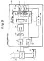
- Figure 1 is a construction diagram of a television signal and an ATM cell switching system according to a first embodiment of the present invention
- In Fig. 1, 60 is a cable television head end (CATV-HE) that is a source for transmitting a plurality of channels CH0, CH1, CH2, ... of television signals, 61 is a normal space-division type synchronous transfer mode switch (STM-SW) for switching the television signals in accordance with requests from the subscribers to provide a plurality of television signal outputs directing to said subscribers respectively; 62 is a multiplexer (MUX) for multiplexing ATM cells of data from a network of, for example, a public network of 64 KHz, other than the television signals to output multiplexed ATM cells of 150 MHz, for example; 63 is an asynchronous transfer mode switch (ATM-SW) for switching the ATM cells to output, for example, 1.2 GHz of ATM cells, 64 is a demultiplexer (DMUX) for demultiplexing the 1.2 GHz ATM cells into ATM cells of 150 MHz corresponding to respective subscribers; 65 represents multiplexing circuits each for multiplexing the television signal and the ATM cell corresponding to one subscriber; 66 represents subscriber interface circuits (SINF), and 67 represents network terminators (NT) each for supplying one of the channels of television signals and data other than the television signals to each of the subscribers.
- In the construction shown in Fig. 1, digital signals for usual data communication, personal computer communication, speech sound, and so forth, are input, in the form of ATM cells, to the
multiplexer 62 and are multiplexed, then switched and connected by the ATM-SW 63, demultiplexed by the demultiplexer to correspond to respective subscribers, and are input to themultiplexer 65. - On the other hand, cable television signals (digital signals) are output from the CATV-
HE 60 as respective channels (CH0, CH1, ...), and are input to the STM-SW 61. In response to requests from respective subscribers, the space division switch STM-SW 61 performs a switching and connection by software. Thus, desired channel signals are output to the output lines corresponding to respective subscribers, and are input to themultiplexing circuits 65 provided to correspond to therespective subscriber circuits 66. - Thus one-way communication of the television signals from the source to the subscribers and two-way communication of the data other than the television signals between the network and the subscribers are carried out.
- The system shown in Fig. 1, however, has the following disadvantage.
- The
respective subscriber circuits 66 are connected through subscriber lines to thenetwork terminators 67. To eachnetwork terminator 67, a plurality of terminal adapters (not shown in Fig. 1 but are shown in Fig. 4) are connected in parallel formation. Corresponding to the terminal adapters, a TV unit, a personal computer, a data terminal, and so forth are respectively connected so that communication is possible among a plurality of units. Note that, between thesubscriber circuit 66 and thenetwork terminator 67, a transmission is performed in accordance with, for example, STS-n (Synchronous Transfer Signal Level n). When it is at level 3 (STS-3) where n = 3, a transmission is performed by 155.52 Mbps (megabits per second). - When the STS-3 is employed, the ATM cells at each output of the
demultiplexer 64 forms an approximately 150 MHz band that can be divided by VCIs (Virtual Call Identifications) in the respective ATM cells. However, the television signals passed through the STM-SW 61 are not the ATM cells but has a broader band than each ATM cell. When one channel of the television signal is 150 MHz, and the communication line between thesubscriber circuit 66 and a terminal of the subscriber allows only 155 MHz, the down line is occupied by only one channel of the television signal so that communication of signals other than the television signal cannot occur because the ATM cells are temporary stored in a buffer (not shown) but the television signal is a continuous signal so that it is not buffered but selected to be output from themultiplexers 65 with a priority even while the ATM cells have to wait to pass the multiplexer. Since the television signal is transmitted by one-way communication, the up-line becomes empty. - Even when communication from the
multiplexing circuit 65 through thesubscriber circuit 66 to the subscriber is made possible by, for example 600 MHz (STS-12) in stead of the above example of STS-3, and if 3/4 band (450 MHz) is always reserved for the television signal, then only 1/4 band (150 MHz) can be used for signals other than the television signals. Assume that one channel of the television signal uses 150 MHz. Then, in the above example, one subscriber always receives three channels of television signals simultaneously. Therefore, there is a problem in that, for communication other than the television signal transmission, only 1/4 band (150 MHz) can be used. There may be a case in which 150 MHz is insufficient for communication other than the television signal transmission. Further, in this case, since the down direction line uses the broad 3/4 band of one-way communication of the television signals, the up direction line cannot use such a broad band. Therefore, there is a using rate imbalance problem between the down line and the up line. Further, there is bad efficiency if units for the broad band are provided, because the units for the broad band cannot be used in communication through the up-line. More over, the band necessary for a video image of a television is generally 70 to 80 MHz, and even for a HD (High Density) TV, 110 to 120 MHz so that the whole band of 150 MHz for one channel cannot be used. - Figure 2 is a block diagram of a television signal and ATM cell switching system according to a second embodiment of the present invention, which is considered to remove the above disadvantage in the system shown in Fig. 1. In the construction in Fig. 2, 68 is a concentrator (represented by RE: an abbreviation of a remote electronics) for concentrating a plurality of subscriber lines at a location far from a network such as a LAN, 680 and 681 are fiber interfaces (FINF) for taking interfaces with the CATV-
HE 60 and a network connected through optical fibers respectively, 682 represents multiplexing circuits, 683 is an ATM-SW, 684 is a demultiplexing circuit, and theSINFs 66 are the same subscriber circuits as those shown in Fig. 1. - In this construction, a television signal output from the CATV-
HE 60 is converted by anATM cell generator 601 into the format of an ATM cell that is input to theFINF 680. The signals other than the television signals are input to the FINF 681. Both the television signals and the usual data in the form of ATM cells are multiplexed by themultiplexing circuits 682 respectively and are switched by the ATM-SW 683. Thedemultiplexer 684 separates the ATM cells into signals corresponding to the respective subscribers and the separated signals are output to thesubscriber circuits 66. - Thus, one way-communication of the television signal and two-way communication of data other than the television signals may be possible.
- The system shown in Fig. 2, however, also has the following disadvantage.
- Namely, in the ATM-
SW 683, one ATM cell generally has only a single destination as a subscriber. Therefore, one channel of the television signal can be delivered to only a single subscriber so that a broad casting function, in which the signal in the same channel is transmitted to a plurality of subscribers, cannot be realized. Even when a broad casting is made possible in the system shown in Fig. 2 so that an ATM cell received from the CATV-HE 60 is always delivered to all subscribers, the using rate of the ATM-SW 683 is increased so that the communication band for other communication (data communication, television telephone and so forth) between subscribers becomes very narrow, resulting in bad efficiency. - In more detail, in the system shown in Fig. 2, when an ATM cell provided with a VCI for each channel of the respective television channel is sent, the concentrator RE cannot perform a broad casting function, because in the exchanging operation, one cell is transferred to only a single target location (destination). If an exchange operation is made so that a broad casting cell is delivered to all subscribers, there is a problem in that memories provided at the respective cross points of the ATM-SW are always used, for example, n × 80 MHz (n is the number of the broad casting channels) so that the band to be used for other purposes (data communication, television telephone, personal computer communication and so forth) becomes narrow.
- Since the television signal requires an extremely broad transmission band, efficient exchange and connection cannot be performed by the system shown in Fig. 1 or Fig. 2. Therefore, an improvement thereof has been desired.
- Fig. 3 is a diagram of a television signal and ATM cell switching system according to a third embodiment of the present invention.
- In Fig. 3, 1 is a cell inserting unit for inserting a television signal cell of a designated channel into data signal cells output from an ATM switch other than the television signals; 10 is a demultiplexing circuit; 11 represents multiplexing circuits provided to correspond to respective subscribers; 2 is a designated channel selecting unit; 3 is the ATM switch ( ATM-SW), and 4 is a television signal transmitting unit for transmitting multichannel television signals that are made to be ATM cells by an
ATM cell generator 41. - As can be seen from Fig. 3, in the third embodiment of the present invention, the television signals that are made to be the ATM cells by the
ATM cell generator 41 are inserted, without passing through the ATM switch 3, in a portion of a subscriber interface. - In an operation of the system shown in Fig. 3, ATM cells of data signals other than the television signals are output from the ATM switch 3 and are input to the
cell inserting unit 1. In each ATM cell, as is well known, a VPI (Virtual Path Identification number) and a VCI (Virtual Channel Identification number) are included in the header, i.e., the heading five octets of the ATM cell. The VCI indicates a particular subscriber as a destination of the ATM cell. Thedemultiplexing circuit 10 separates the ATM cells to be directed to destination subscribers in accordance with the VCIs. The separated ATM cells are input to themultiplexers 11 corresponding to the respective subscribers. Note that, in Fig. 3, for the sake of simplicity, only twomultiplexers 11 are shown, however, the number of multiplexers is the same as the number of subscribers. - On the other hand, from the television
signal transmitting unit 4, multi-channel television signals are output as multiplexed ATM cells and are input to therespective multiplexing circuits 11 in thecell inserting unit 1. The ATM cells from thedemultiplexing circuit 10 and one channel of the television signals selected from the multi-channel television signals output from the televisionsignal transmitting unit 4 are selected and are multiplexed to be transmitted to the subscriber sides. - The channel to be selected from the multi-channel television signals is designated by the designated
channel selecting unit 2. When the designatedchannel selecting unit 2 receives, through a D channel that is used in an integrated services digital network (ISDN) as a channel for passing control signals between a subscriber and the switch, the number of the channel that is desired by a subscriber, theunit 2 outputs an instruction to select the said channel to one or more of the multiplexingcircuits 11. - In response to the instruction, each of the multiplexing
circuits 11 detects the ATM cell of the television signal of the requested channel among the television signals of a plurality of channels, converts the destination (VCI) in the cell into a VCI of the subscriber connected to themultiplexing circuit 11, and transmits the cell to the subscriber side. - Thus, the respective subscribers can receive, from the multiplexing
circuits 11, ATM cells of data signals other than the television signals and ATM cells of the television signal of the requesting channel. - Figure 4 is a system construction diagram of a network in which the present invention is implemented; Fig. 5 is a diagram of the construction of an embodiment of a concentrator; Fig. 6 is a diagram of the construction of a cell inserting unit; and Fig. 7 is a diagram of the construction of a multiplexing circuit.
- In Fig. 4, 20 is a network, such as a local area network (LAN), formed to be a loop by an optical cable for television broad casting (for one-way communication in the down side) and two optical cables for various data other than the television signals (for two-way communication); 21 represents optical fiber loop multiplexers (represented by FLM) for connecting various units to the
network 20; 22 is a control office (CO); 23 is a CATV-HE for television broad casting controlled by thecontrol office 22; 24 represents concentrators (represented by RE) for concentrating plural subscriber lines and for performing switching and connection; 25 represents network terminators (NT) of the respective subscriber lines, 26 represent terminal adapters (represented by TA) for taking interfaces between a plurality of terminals to be connected to the respective subscriber lines and the NTs. - With respect to usual data signals between plural subscribers other than the television signals, paths are set from a
concentrator 24 through aFLM 21, thenetwork 20, anotherFLM 21, aconcentrator 24, a network termination (NT) 25, and terminal adapters (TA) 26, to various terminals (personal computers, facsimile machines, telephone sets, etc., which are not shown in the figure), so that communication by using ATM cells is performed therebetween. - The television signals of plural channels from the CATV-
HE 23 for television broad casting are made to be ATM cells in the CATV-HE 23 or are made to be ATM cells at some stage along the way (for example, at the RE 24). Then, the ATM cells are transmitted through an optical cable for the television signals in the network (NW) 20 to FLMs 21 to which theconcentrators 24 are connected. In theFLMs 21, the ATM cells are branched and are input to the concentrators (RE) 24 from which the ATM cells reach the network terminators (NT) 25 corresponding to the respective subscribers. From the network terminators ( NT) 25, the ATM cells are supplied to one of the TV terminals (not shown) in the respective terminal adapters (TA) 26 for the subscribers. - Figure 5 shows an example of the construction of the concentrator (RE) 24 shown in Fig. 4.
- In Fig. 5, the
reference numerals 20 to 23 are the network, the FLM, and the CATV-HE, respectively, as shown in Fig. 4, and 30 represents a concentrator (corresponding to 24 in Fig. 4). In theconcentrator - In operation of the
concentrator 24, when the television signals from the CATV-HE 23 are input through theFLM 21 to theFINF 32, theFINF 32 directly passes them to the TVcell inserting circuit 35 when the television signals have been made to be ATM cells. When the television signals from theFLM 21 are not made to be ATM cells, theFINF 32 makes them into ATM cells and then supplies them to the TVcell inserting circuit 35. - ATM cells of usual data signals other than the television signals pass through the
FLM 21 andFINF 31 to the multiplexing circuit (MUX) 33 ,in which a plurality of inputs (only one is shown in the figure for the sake of simplicity) are multiplexed, and then switching is effected in the ATM-SW 34. The output thereof is input to the demultiplexing circuit (DMX) 350 in the TVcell inserting circuit 35. - The TV
cell inserting circuit 35 consists of the demultiplexing circuit (DMX) 350 and multiplexing circuits (MUX) 351 and 352 for multiplexing the ATM cells from thedemultiplexing circuit 350 and the ATM cells of a channel designated from the television signals. - When the
CPR 38 receives channel information of a television signal required by a subscriber through a control channel (called a D channel) that is formed between the subscriber terminal and theCPR 38 through the subscriber circuit (SINF) 36 or 37 connected to each subscriber, theCPR 38 generates an instruction, which is given to themultiplexing circuit cell inserting circuit 35. Note that theCPR 38 detects the state of the transfer operations in theFINFs - Figure 6 shows an example of the construction of the TV cell inserting circuit. Note, however, that Fig. 6 shows the construction for only the
SINF 36 in the TVcell inserting circuit 35 for one subscriber. - In Fig. 6, 350 is a part of the demultiplexing circuit (DMX) for one subscriber. The
demultiplexing circuit 350 is represented by thesame symbol 350 in Fig. 5.Reference numeral 351 represents the multiplexing circuit (MUX) 351 in Fig. 5, andSINF 36 andCPR 38 are the same units as those shown in Fig. 5. A linea conducts ATM cells of usual data transferred from the ATM-SW 34 in Fig. 5. A lineb conducts ATM cells of television signals transferred from theFINF 32. A line c connects theDMX 350 and theMUX 351 to form a ring so as to conduct a tolken therethrough. And a line d is connected to theSINF 36 that is provided to correspond to a subscriber. - In operation of the device shown in Fig. 6, when an ATM cell of usual data from the linea is input to the
DMX 350, a VCI included in the header of the ATM cell and the data in asetting unit 3502, in which a VCI is allocated to the subscriber, are compared by acoincidence circuit 3501. When they coincide, thecoincidence circuit 3501 stores the ATM cell into a memory (not shown), from which the ATM cell is output to the line d. The output of the ATM cell to the line d is controlled by the tolken passing through the linec that forms a loop. The control by the tolken is later described with reference to Fig. 7. Thus, the ATM cell of usual data other than the television signals and having a destination to the destination subscriber is separated from the other ATM cells by thedemultiplexer 350 and is output therefrom. - Note that, in the
coincidence circuit 3501, in stead of comparing the VCIs, when a well known method is employed in which tag data corresponding to the destination is added to the ATM cell, it is also possible that tag data indicating the destination of the subscriber may be set in thesetting unit 3502, and a coincidence with the tag data of the input ATM cell may be detected. - To the
multiplexing circuit 351, an ATM cell of a television signal is input through the line b. In the header of the ATM cell of the television signal, data indicating a channel is set as a VCI when the television signal is made to be the ATM cell in the CATV-HE 23 or theFINF 32. For example, CH1 (channel 1) is expressed by VCI = 1, CH2 is expressed by VCI = 2, .. ., and CHn is expressed by VCI = n. - On the other hand, as described with reference to Fig. 5, when the
CPR 38 receives channel information (required channel number) of the television signal that is requested by a subscriber through the control channel (D channel), theCPR 38 sets the VCI of the channel information in asetting unit 3512 in theMUX 351. For example, when it is CH1, "1" is set. Acoincidence circuit 3511 in theMUX 351 compares the VCI in the header of the ATM cell of the television signal and the value in thesetting unit 3512. When they coincide, the ATM cell of the television signal is stored in a memory (not shown) and when theMUX 351 receives the tolken through the line c, the ATM cell of the television signal is read from the memory to be output and is multiplexed with the ATM cell from thedemultiplexer 350. The multiplexed ATM cells are output to the line d. - Figure 7 shows an example of the construction of the multiplexing circuit (MUX) 351 in Fig. 6.
- In Fig. 7, 3511 and 3512 are the coincidence circuit and the setting circuit respectively, which are the same as those shown in Fig. 6, and 3513 is a VCI converting circuit; 3514 is a FIFO (First In First Out) register, and 3515 is a read control circuit.
- In an operation of the circuit shown in Fig. 7, in the
setting unit 3512, the channel number requested by a subscriber designated by theCPR 38 in Fig. 5 and the VCI data of the subscriber (VCI allocated for communication with the destination subscriber) are set. When a television signal (about 1.2 GHz) is input through the lineb to theMUX 351, the VCI in the header of the ATM cell and the channel number set in thesetting unit 3512 are compared in the comparingcircuit 3511. When they coincide, a signal (expressed by GATE) for opening a gate is supplied to theFIFO register 3514, whereby a data signal (expressed by DATA) of the ATM cell is input to theFIFO register 3514. - Also, by the coincidence output from the
coincidence circuit 3511, theVCI converting circuit 3513 is driven. TheVCI converting circuit 3513 converts or rewrites the VCI representing a channel number stored in theFIFO register 3514 into the VCI data of the destination subscriber set in thesetting unit 3512. - The contents in the
FIFO register 3514 are read from theread control circuit 3513 in a first-in first out fashion. The read operation is carried out when the tolken that is circulating through the linec shown in Fig. 6 reaches theMUX 351, and the read ATM cell is output to the line d to be multiplexed with the ATM cell from theDMX 350 shown in Fig. 6. The multiplexed signal is supplied to the SINF (subscriber interface) 36. Although the detailed construction of the DMX 350 (Fig. 6) is not shown, similar to Fig. 7, an ATM cell of usual data other than the television signal is temporarily stored in a FIFO, and when the tolken reaches theDMX 350, the ATM cell is read out to the line d. - From the foregoing description, it will be apparent that, according to the present invention, CATV television signals can be multiplexed with ATM cells in a public network such as an ISDN or ATM network. Further, a band can be efficiently used compared with the case when a television signal is switched in accordance with STM (synchronous transfer mode). For example, when a STM (synchronous transfer mode) is used, and if a transmission line of 150 MHz is used, the whole band of 150 MHz is used even for a 80 MHz band data. In contrast, when the 80 MHz data is made to be ATM cells, only the 80 MHz band is used. Therefore, a 70 MHz band can be saved (150MHz-80MHz) .
- Also, by inserting the television signal without passing through an ATM switch and before the subscriber circuit (SINF), the band in the ATM switch can be efficiently used so that usual data communication other than the television signal obtains a margin in the frequency band. For example, if n channels of the television signals are not used in the ATM switch, about 80 MHz x n (channels) can be efficiently used.
Claims (4)
- A television signal and ATM cell switching system in an exchange apparatus for performing data switching of ATM cells and for supplying one channel among television signals of a plurality of channels transmitted from a source to a subscriber, comprising:a television signal transmitting means (4) for transmitting television signals in the form of ATM cells;an ATM switching means (3) for switching ATM cell data other than said television signals;a television signal cell inserting circuit (1), operatively connected to said television signal transmitting means (4) and said ATM switching means (3), for receiving a plurality of channels of the television signals from said television signal transmitting means (4), and for receiving the ATM cell data other than said television signals after being switched by said ATM switching means (3); anddesignated channel selecting means (2), operatively connected to a plurality of multiplexing circuits (11), for providing a channel designating signal to each of said multiplexers (11) in accordance with a request from the corresponding subscriber, each of said multiplexing circuits (11) being operable to select one channel of the television signals in accordance with said channel designating signal.
- A television signal and ATM cell switching system according to claim 1 whereinsaid television signal inserting circuit (1) comprises:a demultiplexing circuit (10), operatively connected to said ATM switching means (3), for demultiplexing the output of said ATM switching means .(3) to provide a plurality of outputs corresponding to respective subscribers; andsaid plurality of multiplexing circuits (11), operatively connected to the outputs of said demultiplexing circuit (10) respectively and connected to said television signal transmitting means (4), each for multiplexing the demultiplexed ATM cell received from one corresponding output of said demultiplexing circuit (10) and one channel of the ATM cells selected in accordance with a request from the corresponding subscriber;whereby one-way communication of said television signals from said source to said subscribers and two-way communication of said data other than said television signals between said network and said subscribers are carried out.
- A television signal and ATM cell switching system as claimed in claim 2, wherein an ATM cell in each channel of the television signals is provided with a VCI area , and when one of said multiplexing circuits detects an ATM cell representing the television signal of the channel requested by a subscriber, said multiplexing circuit writes a VCI, indicating that the destination of said ATM cell is said subscriber, into said VCI area.
- A television signal and ATM cell switching system as claimed in claim 2, wherein each of said plurality of multiplexing circuits (11) in said television signal inserting circuit is driven by a token circulating through said plurality of multiplexing circuits (11) to output an ATM cell to the corresponding subscriber.
Priority Applications (1)
| Application Number | Priority Date | Filing Date | Title |
|---|---|---|---|
| EP19960101410EP0715470B1 (en) | 1991-05-14 | 1992-05-13 | System for supplying a plurality of ATM cells |
Applications Claiming Priority (2)
| Application Number | Priority Date | Filing Date | Title |
|---|---|---|---|
| JP108059/91 | 1991-05-14 | ||
| JP10805991AJP2938611B2 (en) | 1991-05-14 | 1991-05-14 | TV signal exchange system |
Related Child Applications (2)
| Application Number | Title | Priority Date | Filing Date |
|---|---|---|---|
| EP19960101410DivisionEP0715470B1 (en) | 1991-05-14 | 1992-05-13 | System for supplying a plurality of ATM cells |
| EP96101410.7Division-Into | 1992-05-13 |
Publications (3)
| Publication Number | Publication Date |
|---|---|
| EP0513763A2 EP0513763A2 (en) | 1992-11-19 |
| EP0513763A3 EP0513763A3 (en) | 1993-03-03 |
| EP0513763B1true EP0513763B1 (en) | 1996-09-04 |
Family
ID=14474867
Family Applications (2)
| Application Number | Title | Priority Date | Filing Date |
|---|---|---|---|
| EP19960101410Expired - LifetimeEP0715470B1 (en) | 1991-05-14 | 1992-05-13 | System for supplying a plurality of ATM cells |
| EP19920108080Expired - LifetimeEP0513763B1 (en) | 1991-05-14 | 1992-05-13 | Television signal and ATM cell switching system |
Family Applications Before (1)
| Application Number | Title | Priority Date | Filing Date |
|---|---|---|---|
| EP19960101410Expired - LifetimeEP0715470B1 (en) | 1991-05-14 | 1992-05-13 | System for supplying a plurality of ATM cells |
Country Status (5)
| Country | Link |
|---|---|
| US (1) | US5513180A (en) |
| EP (2) | EP0715470B1 (en) |
| JP (1) | JP2938611B2 (en) |
| CA (1) | CA2068387C (en) |
| DE (2) | DE69213317T2 (en) |
Cited By (17)
| Publication number | Priority date | Publication date | Assignee | Title |
|---|---|---|---|---|
| US6539548B1 (en) | 1992-12-09 | 2003-03-25 | Discovery Communications, Inc. | Operations center for a television program packaging and delivery system |
| US7017178B1 (en) | 1992-12-09 | 2006-03-21 | Sedna Patent Services, Llc | Audio program reception terminal for television delivery system |
| US7073187B1 (en) | 1992-12-09 | 2006-07-04 | Sedna Patent Services, Llc | Menu-driven television program access system and method |
| US7207055B1 (en) | 1992-12-09 | 2007-04-17 | Sedna Patent Services, Llc | Bandwidth allocation for a television program delivery system |
| US7269841B1 (en) | 1992-12-09 | 2007-09-11 | Sedna Patent Services, Llc | Digital cable headend for cable television delivery system |
| US7336788B1 (en) | 1992-12-09 | 2008-02-26 | Discovery Communicatoins Inc. | Electronic book secure communication with home subsystem |
| US7401286B1 (en) | 1993-12-02 | 2008-07-15 | Discovery Communications, Inc. | Electronic book electronic links |
| US7509270B1 (en) | 1992-12-09 | 2009-03-24 | Discovery Communications, Inc. | Electronic Book having electronic commerce features |
| US7590993B1 (en) | 1992-12-09 | 2009-09-15 | Comcast Ip Holdings I, Llc | Method and apparatus for gathering programs watched data |
| US7835989B1 (en) | 1992-12-09 | 2010-11-16 | Discovery Communications, Inc. | Electronic book alternative delivery systems |
| US7849393B1 (en) | 1992-12-09 | 2010-12-07 | Discovery Communications, Inc. | Electronic book connection to world watch live |
| US7861166B1 (en) | 1993-12-02 | 2010-12-28 | Discovery Patent Holding, Llc | Resizing document pages to fit available hardware screens |
| US7865567B1 (en) | 1993-12-02 | 2011-01-04 | Discovery Patent Holdings, Llc | Virtual on-demand electronic book |
| US8073695B1 (en) | 1992-12-09 | 2011-12-06 | Adrea, LLC | Electronic book with voice emulation features |
| US8095949B1 (en) | 1993-12-02 | 2012-01-10 | Adrea, LLC | Electronic book with restricted access features |
| US9009773B1 (en) | 1998-06-30 | 2015-04-14 | Cox Communications, Inc. | Method and apparatus for providing broadcast data services |
| US9053640B1 (en) | 1993-12-02 | 2015-06-09 | Adrea, LLC | Interactive electronic book |
Families Citing this family (84)
| Publication number | Priority date | Publication date | Assignee | Title |
|---|---|---|---|---|
| EP0580011A3 (en)* | 1992-07-23 | 1994-09-14 | Siemens Ag | Method for the transmission of digital video and audio signals and suitable receiving apparatus |
| US9286294B2 (en) | 1992-12-09 | 2016-03-15 | Comcast Ip Holdings I, Llc | Video and digital multimedia aggregator content suggestion engine |
| US7168084B1 (en) | 1992-12-09 | 2007-01-23 | Sedna Patent Services, Llc | Method and apparatus for targeting virtual objects |
| US5425027A (en)* | 1993-01-04 | 1995-06-13 | Com21, Inc. | Wide area fiber and TV cable fast packet cell network |
| US5539449A (en)* | 1993-05-03 | 1996-07-23 | At&T Corp. | Integrated television services system |
| CA2165424A1 (en)* | 1993-06-16 | 1994-12-22 | Paul Baran | Multiple protocol personal communications network system |
| EP0803156B1 (en) | 1994-05-05 | 2004-12-01 | Sprint Communications Company, L.P. | Method, system and apparatus for telecommunications control |
| US5991301A (en)* | 1994-05-05 | 1999-11-23 | Sprint Communications Co. L.P. | Broadband telecommunications system |
| US6633561B2 (en) | 1994-05-05 | 2003-10-14 | Sprint Communications Company, L.P. | Method, system and apparatus for telecommunications control |
| US6631133B1 (en) | 1994-05-05 | 2003-10-07 | Sprint Communications Company L.P. | Broadband telecommunications system |
| US6031840A (en)* | 1995-12-07 | 2000-02-29 | Sprint Communications Co. L.P. | Telecommunications system |
| US6430195B1 (en)* | 1994-05-05 | 2002-08-06 | Sprint Communications Company L.P. | Broadband telecommunications system interface |
| US5920562A (en) | 1996-11-22 | 1999-07-06 | Sprint Communications Co. L.P. | Systems and methods for providing enhanced services for telecommunication call |
| US6181703B1 (en) | 1995-09-08 | 2001-01-30 | Sprint Communications Company L. P. | System for managing telecommunications |
| DE4425197C2 (en)* | 1994-07-16 | 1998-07-09 | Deutsche Telekom Ag | Method for return channel transmission in broadband distribution networks |
| US5757798A (en)* | 1994-07-21 | 1998-05-26 | Hitachi, Ltd. | Image information distribution system |
| CN1122087A (en)* | 1994-07-21 | 1996-05-08 | 株式会社日立制作所 | Image Information Distribution System |
| EP0701384B1 (en)* | 1994-09-09 | 2003-01-02 | Alcatel | System, subscriber equipment, central and method for video on demand |
| CA2199815C (en)* | 1994-09-12 | 2001-07-24 | Catherine W. Jelinek | Cable television apparatus employing two-way communication |
| DE4433898C2 (en)* | 1994-09-22 | 1997-08-14 | Siemens Ag | Broadband information system for interactive services |
| CA2143977C (en)* | 1995-01-31 | 1997-03-18 | Mark Krebs | Video mail delivery system |
| EP0735766B1 (en)* | 1995-03-31 | 2002-07-03 | Sony Service Centre (Europe) N.V. | A video service system with VCR function |
| EP0735763B1 (en) | 1995-03-31 | 2000-07-05 | Sony Europa B.V. | A system for information on demand |
| JP3231575B2 (en)* | 1995-04-18 | 2001-11-26 | 三菱電機株式会社 | Wireless data transmission equipment |
| US6209132B1 (en) | 1995-06-15 | 2001-03-27 | Intel Corporation | Host apparatus for simulating two way connectivity for one way data streams |
| US6072521A (en)* | 1995-06-15 | 2000-06-06 | Intel Corporation | Hand held apparatus for simulating two way connectivity for one way data streams |
| US6064420A (en)* | 1995-06-15 | 2000-05-16 | Intel Corporation | Simulating two way connectivity for one way data streams for multiple parties |
| US5818441A (en)* | 1995-06-15 | 1998-10-06 | Intel Corporation | System and method for simulating two-way connectivity for one way data streams |
| US5826166A (en)* | 1995-07-06 | 1998-10-20 | Bell Atlantic Network Services, Inc. | Digital entertainment terminal providing dynamic execution in video dial tone networks |
| US5996019A (en) | 1995-07-19 | 1999-11-30 | Fujitsu Network Communications, Inc. | Network link access scheduling using a plurality of prioritized lists containing queue identifiers |
| AU717210B2 (en)* | 1995-09-07 | 2000-03-23 | Nec Australia Pty Ltd | A distribution system |
| WO1997009827A1 (en)* | 1995-09-07 | 1997-03-13 | Nec Australia Pty. Ltd. | A distribution system |
| WO1997010656A1 (en) | 1995-09-14 | 1997-03-20 | Fujitsu Network Communications, Inc. | Transmitter controlled flow control for buffer allocation in wide area atm networks |
| US6687244B1 (en) | 1995-11-22 | 2004-02-03 | Sprint Communications Company, L.P. | ATM transport system |
| US7003796B1 (en)* | 1995-11-22 | 2006-02-21 | Samsung Information Systems America | Method and apparatus for recovering data stream clock |
| AU1697697A (en) | 1996-01-16 | 1997-08-11 | Fujitsu Limited | A reliable and flexible multicast mechanism for atm networks |
| WO1997028622A1 (en)* | 1996-02-02 | 1997-08-07 | Sprint Communications Company, L.P. | Atm gateway system |
| AU6350196A (en)* | 1996-07-08 | 1998-02-02 | Mark Sinclair Krebs | Video mail delivery system |
| JPH1065670A (en)* | 1996-08-13 | 1998-03-06 | Nec Corp | Atm concentrator |
| US5748905A (en) | 1996-08-30 | 1998-05-05 | Fujitsu Network Communications, Inc. | Frame classification using classification keys |
| US6028860A (en)* | 1996-10-23 | 2000-02-22 | Com21, Inc. | Prioritized virtual connection transmissions in a packet to ATM cell cable network |
| WO1998020638A1 (en)* | 1996-11-08 | 1998-05-14 | 3Com | Mechanism to support a utopia interface over a backplane |
| US6014378A (en) | 1996-11-22 | 2000-01-11 | Sprint Communications Company, L.P. | Telecommunications tandem system for circuit-based traffic |
| US6002689A (en) | 1996-11-22 | 1999-12-14 | Sprint Communications Co. L.P. | System and method for interfacing a local communication device |
| US5905942A (en)* | 1997-02-18 | 1999-05-18 | Lodgenet Entertainment Corporation | Multiple dwelling unit interactive audio/video distribution system |
| US5946048A (en)* | 1997-03-12 | 1999-08-31 | Hybrid Networks, Inc. | Network device for handling digital data over a TV channel |
| US5946047A (en)* | 1997-03-12 | 1999-08-31 | Hybrid Networks, Inc. | Network system for handling digital data over a TV channel |
| US6067299A (en) | 1997-04-16 | 2000-05-23 | Sprint Communications Company, L.P. | Communications system for providing ATM connections and echo cancellation |
| US6137800A (en) | 1997-05-09 | 2000-10-24 | Sprint Communications Company, L. P. | System and method for connecting a call |
| US6704327B1 (en) | 1997-05-09 | 2004-03-09 | Sprint Communications Company, L.P. | System and method for connecting a call |
| US6178170B1 (en) | 1997-05-13 | 2001-01-23 | Sprint Communications Company, L. P. | System and method for transporting a call |
| AUPO894297A0 (en)* | 1997-09-02 | 1997-09-25 | Nec Australia Pty Ltd | A distribution system |
| US6031576A (en)* | 1997-09-08 | 2000-02-29 | Kuykendall, Jr.; Jacob L. | Method and system for over-the-air broadcast of HDTV and the like with efficient spectrum allocation and broadcast area signal distribution |
| JP3831092B2 (en)* | 1997-09-19 | 2006-10-11 | 富士通株式会社 | server |
| US6470019B1 (en) | 1998-02-20 | 2002-10-22 | Sprint Communications Company L.P. | System and method for treating a call for call processing |
| US6546022B1 (en)* | 1998-04-03 | 2003-04-08 | Sprint Communications Company, L.P. | Method, system and apparatus for processing information in a telecommunications system |
| US6597701B1 (en) | 1998-12-22 | 2003-07-22 | Sprint Communications Company L.P. | System and method for configuring a local service control point with a call processor in an architecture |
| US6724765B1 (en) | 1998-12-22 | 2004-04-20 | Sprint Communications Company, L.P. | Telecommunication call processing and connection system architecture |
| US6785282B1 (en) | 1998-12-22 | 2004-08-31 | Sprint Communications Company L.P. | System and method for connecting a call with a gateway system |
| US6888833B1 (en) | 1998-12-22 | 2005-05-03 | Sprint Communications Company L.P. | System and method for processing call signaling |
| US6982950B1 (en) | 1998-12-22 | 2006-01-03 | Sprint Communications Company L.P. | System and method for connecting a call in a tandem architecture |
| US7079530B1 (en) | 1999-02-25 | 2006-07-18 | Sprint Communications Company L.P. | System and method for caching toll free number information |
| US6560226B1 (en) | 1999-02-25 | 2003-05-06 | Sprint Communications Company, L.P. | System and method for caching ported number information |
| EP1041825A1 (en)* | 1999-03-31 | 2000-10-04 | Alcatel | Broadcasting unit to broadcast distributive interactive services in an access network |
| FR2794591B1 (en)* | 1999-06-03 | 2001-06-29 | France Telecom | INTERNAL INSTALLATION OF ATM-BASED MULTI-TERMINAL CLIENT |
| US6816497B1 (en) | 1999-11-05 | 2004-11-09 | Sprint Communications Company, L.P. | System and method for processing a call |
| US6785377B1 (en) | 2000-01-19 | 2004-08-31 | Sprint Communications Company L.P. | Data calls using both constant bit rate and variable bit rate connections |
| US7263712B2 (en)* | 2001-05-29 | 2007-08-28 | Intel Corporation | Enabling a PC-DTV receiver to share the resource cache with multiple clients |
| US7793326B2 (en) | 2001-08-03 | 2010-09-07 | Comcast Ip Holdings I, Llc | Video and digital multimedia aggregator |
| US7908628B2 (en) | 2001-08-03 | 2011-03-15 | Comcast Ip Holdings I, Llc | Video and digital multimedia aggregator content coding and formatting |
| US8630306B2 (en)* | 2006-01-09 | 2014-01-14 | At&T Intellectual Property I, L.P. | Fast channel change apparatus and method for IPTV |
| US20090070829A1 (en)* | 2007-09-11 | 2009-03-12 | The Directv Group, Inc. | Receiving circuit module for receiving and encoding channel signals and method for operating the same |
| US9756290B2 (en)* | 2007-09-11 | 2017-09-05 | The Directv Group, Inc. | Method and system for communicating between a local collection facility and a remote facility |
| US8973058B2 (en)* | 2007-09-11 | 2015-03-03 | The Directv Group, Inc. | Method and system for monitoring and simultaneously displaying a plurality of signal channels in a communication system |
| US9300412B2 (en)* | 2007-09-11 | 2016-03-29 | The Directv Group, Inc. | Method and system for operating a receiving circuit for multiple types of input channel signals |
| US9313457B2 (en) | 2007-09-11 | 2016-04-12 | The Directv Group, Inc. | Method and system for monitoring a receiving circuit module and controlling switching to a back-up receiving circuit module at a local collection facility from a remote facility |
| US8988986B2 (en) | 2007-09-12 | 2015-03-24 | The Directv Group, Inc. | Method and system for controlling a back-up multiplexer in a local collection facility from a remote facility |
| US8724635B2 (en)* | 2007-09-12 | 2014-05-13 | The Directv Group, Inc. | Method and system for controlling a back-up network adapter in a local collection facility from a remote facility |
| US9037074B2 (en)* | 2007-10-30 | 2015-05-19 | The Directv Group, Inc. | Method and system for monitoring and controlling a local collection facility from a remote facility through an IP network |
| US9049354B2 (en)* | 2007-10-30 | 2015-06-02 | The Directv Group, Inc. | Method and system for monitoring and controlling a back-up receiver in local collection facility from a remote facility using an IP network |
| US9049037B2 (en)* | 2007-10-31 | 2015-06-02 | The Directv Group, Inc. | Method and system for monitoring and encoding signals in a local facility and communicating the signals between a local collection facility and a remote facility using an IP network |
| US9762973B2 (en)* | 2008-11-04 | 2017-09-12 | The Directv Group, Inc. | Method and system for operating a receiving circuit module to encode a channel signal into multiple encoding formats |
| US8451921B2 (en)* | 2009-10-28 | 2013-05-28 | Qualcomm Incorporated | Method and an apparatus for adaptively learning a sparse impulse response of a continuous channel |
| US9831971B1 (en) | 2011-04-05 | 2017-11-28 | The Directv Group, Inc. | Method and system for operating a communication system encoded into multiple independently communicated encoding formats |
Family Cites Families (8)
| Publication number | Priority date | Publication date | Assignee | Title |
|---|---|---|---|---|
| CA1142244A (en)* | 1979-08-22 | 1983-03-01 | Eric J. Gargini | Wired broadcasting system with subscriber controlled switched programme selection |
| US4509073A (en)* | 1982-04-29 | 1985-04-02 | Packet Technologies, Inc. | Two-way cable-television system |
| US4831616A (en)* | 1987-03-31 | 1989-05-16 | Huber David R | Multiplexed fiber optics wideband data distribution system |
| EP0809381B1 (en)* | 1988-07-22 | 2004-11-24 | Hitachi, Ltd. | ATM switching system |
| JP3132564B2 (en)* | 1988-08-26 | 2001-02-05 | 株式会社日立製作所 | ATM switch |
| US4901367A (en)* | 1988-11-30 | 1990-02-13 | Victor Nicholson | Cable communications system with remote switching and processing converters |
| US4947244A (en)* | 1989-05-03 | 1990-08-07 | On Command Video Corporation | Video selection and distribution system |
| US5115426A (en)* | 1990-03-30 | 1992-05-19 | At&T Bell Laboratories | Broadband isdn packet switching arrangements |
- 1991
- 1991-05-14JPJP10805991Apatent/JP2938611B2/ennot_activeExpired - Fee Related
- 1992
- 1992-05-11CACA 2068387patent/CA2068387C/ennot_activeExpired - Fee Related
- 1992-05-13DEDE69213317Tpatent/DE69213317T2/ennot_activeExpired - Fee Related
- 1992-05-13EPEP19960101410patent/EP0715470B1/ennot_activeExpired - Lifetime
- 1992-05-13DEDE69231285Tpatent/DE69231285T2/ennot_activeExpired - Fee Related
- 1992-05-13EPEP19920108080patent/EP0513763B1/ennot_activeExpired - Lifetime
- 1994
- 1994-03-15USUS08/213,997patent/US5513180A/ennot_activeExpired - Fee Related
Non-Patent Citations (1)
| Title |
|---|
| D'AGOSTINO S.: "UNIVERSAL ATM VIDEO CODING ARCHITECTURE.", ELECTRICAL COMMUNICATION., ALCATEL. BRUSSELS., BE, vol. 64., no. 02 / 03., 1 January 1990 (1990-01-01), BE, pages 186 - 193., XP000237653, ISSN: 0013-4252* |
Cited By (21)
| Publication number | Priority date | Publication date | Assignee | Title |
|---|---|---|---|---|
| US7835989B1 (en) | 1992-12-09 | 2010-11-16 | Discovery Communications, Inc. | Electronic book alternative delivery systems |
| US7865405B2 (en) | 1992-12-09 | 2011-01-04 | Discovery Patent Holdings, Llc | Electronic book having electronic commerce features |
| US7073187B1 (en) | 1992-12-09 | 2006-07-04 | Sedna Patent Services, Llc | Menu-driven television program access system and method |
| US7207055B1 (en) | 1992-12-09 | 2007-04-17 | Sedna Patent Services, Llc | Bandwidth allocation for a television program delivery system |
| US7269841B1 (en) | 1992-12-09 | 2007-09-11 | Sedna Patent Services, Llc | Digital cable headend for cable television delivery system |
| US7336788B1 (en) | 1992-12-09 | 2008-02-26 | Discovery Communicatoins Inc. | Electronic book secure communication with home subsystem |
| US8073695B1 (en) | 1992-12-09 | 2011-12-06 | Adrea, LLC | Electronic book with voice emulation features |
| US7509270B1 (en) | 1992-12-09 | 2009-03-24 | Discovery Communications, Inc. | Electronic Book having electronic commerce features |
| US7590993B1 (en) | 1992-12-09 | 2009-09-15 | Comcast Ip Holdings I, Llc | Method and apparatus for gathering programs watched data |
| US7716349B1 (en) | 1992-12-09 | 2010-05-11 | Discovery Communications, Inc. | Electronic book library/bookstore system |
| US7017178B1 (en) | 1992-12-09 | 2006-03-21 | Sedna Patent Services, Llc | Audio program reception terminal for television delivery system |
| US7849393B1 (en) | 1992-12-09 | 2010-12-07 | Discovery Communications, Inc. | Electronic book connection to world watch live |
| US6539548B1 (en) | 1992-12-09 | 2003-03-25 | Discovery Communications, Inc. | Operations center for a television program packaging and delivery system |
| US7401286B1 (en) | 1993-12-02 | 2008-07-15 | Discovery Communications, Inc. | Electronic book electronic links |
| US7865567B1 (en) | 1993-12-02 | 2011-01-04 | Discovery Patent Holdings, Llc | Virtual on-demand electronic book |
| US7861166B1 (en) | 1993-12-02 | 2010-12-28 | Discovery Patent Holding, Llc | Resizing document pages to fit available hardware screens |
| US8095949B1 (en) | 1993-12-02 | 2012-01-10 | Adrea, LLC | Electronic book with restricted access features |
| US9053640B1 (en) | 1993-12-02 | 2015-06-09 | Adrea, LLC | Interactive electronic book |
| US9009773B1 (en) | 1998-06-30 | 2015-04-14 | Cox Communications, Inc. | Method and apparatus for providing broadcast data services |
| US8548813B2 (en) | 1999-06-25 | 2013-10-01 | Adrea, LLC | Electronic book with voice emulation features |
| US9099097B2 (en) | 1999-06-25 | 2015-08-04 | Adrea, LLC | Electronic book with voice emulation features |
Also Published As
| Publication number | Publication date |
|---|---|
| EP0715470A3 (en) | 1996-08-14 |
| DE69213317D1 (en) | 1996-10-10 |
| DE69231285D1 (en) | 2000-08-24 |
| EP0715470A2 (en) | 1996-06-05 |
| JPH04336830A (en) | 1992-11-25 |
| CA2068387A1 (en) | 1992-11-15 |
| EP0715470B1 (en) | 2000-07-19 |
| CA2068387C (en) | 1998-09-15 |
| US5513180A (en) | 1996-04-30 |
| EP0513763A2 (en) | 1992-11-19 |
| JP2938611B2 (en) | 1999-08-23 |
| DE69213317T2 (en) | 1997-02-20 |
| DE69231285T2 (en) | 2000-12-28 |
| EP0513763A3 (en) | 1993-03-03 |
Similar Documents
| Publication | Publication Date | Title |
|---|---|---|
| EP0513763B1 (en) | Television signal and ATM cell switching system | |
| JP2889013B2 (en) | Packet switching system | |
| US5812550A (en) | Asynchronous transfer mode (ATM) layer function processing apparatus with an enlarged structure | |
| EP0332197B1 (en) | A ring transmission system | |
| US20020097745A1 (en) | Service unit for a hub having multiple star interconnect configurations | |
| RU2209523C2 (en) | Adaptive level 2a (al2a) processing device and method for asynchronous transmission mode network | |
| JP3342500B2 (en) | Multiservice circuits for telecommunications | |
| JP3073248B2 (en) | Point-to-multipoint connection method | |
| GB2285366A (en) | Asynchronous data transfer | |
| JPH09284344A (en) | ATM / STM mixed network system | |
| JPH02140037A (en) | ATM switch | |
| EP0942617B1 (en) | Short cell multiplexing apparatus and method | |
| JPH10233745A (en) | Multiplex transmission method and system | |
| RU2134024C1 (en) | Device and method of processing of elements of data on mode of asynchronous transmission in system of commutation of mode of asynchronous transmission | |
| KR100419110B1 (en) | Telecommunication network elements, synchronous and asynchronous transfer mode payload delivery method, and asynchronous transfer mode cell generation device | |
| JP2002077210A (en) | Pon transmission system, atm-pon transmission system, optical network equipment, and optical circuit terminating device | |
| US20030026284A1 (en) | Digital signal transmission system | |
| Murano et al. | Technologies towards broadband ISDN | |
| KR100237883B1 (en) | Efficient method for cell routing in atm vp cross connector using the method | |
| JP3041091B2 (en) | ATM cross connect device | |
| KR100372876B1 (en) | Apparatus And Method For Subscriber Interface Of STM-4C Grade | |
| KR100287416B1 (en) | Asynchronous Transmission Mode Cell Structure Conversion Method in Demand Dense Optical Subscriber Transmitter | |
| JPH09139744A (en) | Broadband optical transmission system | |
| JPH06268673A (en) | ATM communication system | |
| Nishisno et al. | Broadband switching system configuration and access protocol |
Legal Events
| Date | Code | Title | Description |
|---|---|---|---|
| PUAI | Public reference made under article 153(3) epc to a published international application that has entered the european phase | Free format text:ORIGINAL CODE: 0009012 | |
| AK | Designated contracting states | Kind code of ref document:A2 Designated state(s):DE FR GB | |
| PUAL | Search report despatched | Free format text:ORIGINAL CODE: 0009013 | |
| AK | Designated contracting states | Kind code of ref document:A3 Designated state(s):DE FR GB | |
| 17P | Request for examination filed | Effective date:19930225 | |
| 17Q | First examination report despatched | Effective date:19950224 | |
| GRAH | Despatch of communication of intention to grant a patent | Free format text:ORIGINAL CODE: EPIDOS IGRA | |
| GRAA | (expected) grant | Free format text:ORIGINAL CODE: 0009210 | |
| GRAH | Despatch of communication of intention to grant a patent | Free format text:ORIGINAL CODE: EPIDOS IGRA | |
| AK | Designated contracting states | Kind code of ref document:B1 Designated state(s):DE FR GB | |
| XX | Miscellaneous (additional remarks) | Free format text:TEILANMELDUNG 96101410.7 EINGEREICHT AM 01/02/96. | |
| REF | Corresponds to: | Ref document number:69213317 Country of ref document:DE Date of ref document:19961010 | |
| ET | Fr: translation filed | ||
| PLBI | Opposition filed | Free format text:ORIGINAL CODE: 0009260 | |
| PLBQ | Unpublished change to opponent data | Free format text:ORIGINAL CODE: EPIDOS OPPO | |
| PLBF | Reply of patent proprietor to notice(s) of opposition | Free format text:ORIGINAL CODE: EPIDOS OBSO | |
| 26 | Opposition filed | Opponent name:ALCATEL ALSTHOM COMPAGNIE GENERALE D'ELECTRICITE Effective date:19970604 | |
| PLBF | Reply of patent proprietor to notice(s) of opposition | Free format text:ORIGINAL CODE: EPIDOS OBSO | |
| PLBF | Reply of patent proprietor to notice(s) of opposition | Free format text:ORIGINAL CODE: EPIDOS OBSO | |
| PLBF | Reply of patent proprietor to notice(s) of opposition | Free format text:ORIGINAL CODE: EPIDOS OBSO | |
| PLBL | Opposition procedure terminated | Free format text:ORIGINAL CODE: EPIDOS OPPC | |
| PLBM | Termination of opposition procedure: date of legal effect published | Free format text:ORIGINAL CODE: 0009276 | |
| STAA | Information on the status of an ep patent application or granted ep patent | Free format text:STATUS: OPPOSITION PROCEDURE CLOSED | |
| 27C | Opposition proceedings terminated | Effective date:19990120 | |
| REG | Reference to a national code | Ref country code:GB Ref legal event code:IF02 | |
| PGFP | Annual fee paid to national office [announced via postgrant information from national office to epo] | Ref country code:DE Payment date:20050506 Year of fee payment:14 | |
| PGFP | Annual fee paid to national office [announced via postgrant information from national office to epo] | Ref country code:GB Payment date:20050511 Year of fee payment:14 Ref country code:FR Payment date:20050511 Year of fee payment:14 | |
| PG25 | Lapsed in a contracting state [announced via postgrant information from national office to epo] | Ref country code:GB Free format text:LAPSE BECAUSE OF NON-PAYMENT OF DUE FEES Effective date:20060513 | |
| PG25 | Lapsed in a contracting state [announced via postgrant information from national office to epo] | Ref country code:DE Free format text:LAPSE BECAUSE OF NON-PAYMENT OF DUE FEES Effective date:20061201 | |
| GBPC | Gb: european patent ceased through non-payment of renewal fee | Effective date:20060513 | |
| REG | Reference to a national code | Ref country code:FR Ref legal event code:ST Effective date:20070131 | |
| PG25 | Lapsed in a contracting state [announced via postgrant information from national office to epo] | Ref country code:FR Free format text:LAPSE BECAUSE OF NON-PAYMENT OF DUE FEES Effective date:20060531 | |
| PLAB | Opposition data, opponent's data or that of the opponent's representative modified | Free format text:ORIGINAL CODE: 0009299OPPO |