EP0511741B1 - Enhanced L1/L2 code channel for global positioning system receivers - Google Patents
Enhanced L1/L2 code channel for global positioning system receiversDownload PDFInfo
- Publication number
- EP0511741B1 EP0511741B1EP92302791AEP92302791AEP0511741B1EP 0511741 B1EP0511741 B1EP 0511741B1EP 92302791 AEP92302791 AEP 92302791AEP 92302791 AEP92302791 AEP 92302791AEP 0511741 B1EP0511741 B1EP 0511741B1
- Authority
- EP
- European Patent Office
- Prior art keywords
- code
- signals
- band signal
- phase
- generating
- Prior art date
- Legal status (The legal status is an assumption and is not a legal conclusion. Google has not performed a legal analysis and makes no representation as to the accuracy of the status listed.)
- Expired - Lifetime
Links
Images


Classifications
- G—PHYSICS
- G01—MEASURING; TESTING
- G01S—RADIO DIRECTION-FINDING; RADIO NAVIGATION; DETERMINING DISTANCE OR VELOCITY BY USE OF RADIO WAVES; LOCATING OR PRESENCE-DETECTING BY USE OF THE REFLECTION OR RERADIATION OF RADIO WAVES; ANALOGOUS ARRANGEMENTS USING OTHER WAVES
- G01S19/00—Satellite radio beacon positioning systems; Determining position, velocity or attitude using signals transmitted by such systems
- G01S19/01—Satellite radio beacon positioning systems transmitting time-stamped messages, e.g. GPS [Global Positioning System], GLONASS [Global Orbiting Navigation Satellite System] or GALILEO
- G01S19/13—Receivers
- G01S19/32—Multimode operation in a single same satellite system, e.g. GPS L1/L2
Definitions
- This inventionrelates to Global Positioning System (GPS) receivers and more particularly a method for enhancing a single receiver channel for processing a plurality of L-band signals.
- GPSGlobal Positioning System
- the NAVSTAR Global Positioning Systemis used to determine exact geographic position (i.e. latitude, longitude, and height above the earth) as well as the exact velocity and time of stationary or moving objects.
- the navigation receivercalculates position, and time by determining distance to a series of satellites.
- the navigation receivercalculates velocity by determining doppler frequency shift of the satellite signals.
- the NAVSTAR GPS receivermust receive signals generated from the satellite about 11,000 miles away. Each GPS satellite transmits a 6-watt signal. The satellite and receiver, therefore, employs spread spectrum techniques to differentiate the signal from the noise. This is essential since at the antenna the GPS signal is typically about 20 dB below ambient cosmic noise. "Spread spectrum" means that the frequency or instantaneous phase of the signal being transmitted changes as a function of time. Using spread spectrum signal processing techniques, the receiver can track the spread spectrum signal coming from the satellite by estimating a duplicate image of the signal. A precise match of the satellite's spread spectrum signal produces a potential signal processing gain of up to 53 decibels.
- Each satellitegenerates two spread spectrum signals centered around separate frequencies.
- the L1 channelis centered about 1575.42 MHz, and has course/acquisition-(C/A-) code and precision- (P-) code modulated on it.
- C/A-codehas a 1.023 MHz chipping rate with a band width of about 2 MHz
- P-codehas a 10.23 MHz chipping rate with a bandwidth of about 20 MHz.
- the L2 channelis centered around 1227.6 MHz and only has P-code modulated on it.
- a positioncan be derived from just the C/A- or P-code on the L1 band.
- ionospheric delaythat unpredictably affects the perceived range to the satellite from the receiver.
- These errorscan be corrected by tracking both L1 and L2 and by measuring the difference in the range that is perceived by the receiver on these L-bands. In this manner, the ionospheric errors can be reduced and the navigation solution can be made more accurate by a few meters.
- tracking both L bandssimultaneously provides more anti-jamming immunity for operation in hostile environments.
- a multi-channel GPS digital signal processoris disclosed in published European application No. 501828 A1. Each channel contains circuitry to process high frequency (L1) band signals and low frequency (L2) band signals of either P-code or C/A-code.
- the signal processorincludes a search processor for fast signal acquisition but does not address problems of power consumption and size.
- a GPS receiveris disclosed in published European Application No. 501,829 Al which converts analogue signals to digital signals prior to performing signal acquisition.
- the receiverincludes an A/D converter using full-null-zone processing to increase the anti-jamming capability, but does not address the problem of interchangeably operating single and double looped processing.
- the present inventionprovides apparatus as defined in each of the appended claims 1, 2 and 3 and a method as claimed in claim 10.
- a technical advantage of the present systemis that, by enhancing a single P-code channel, it is possible to obtain the benefit of independent L1 and L2 tracking loops within a GPS system without the penalty of having two independent hardware channels for this purpose.
- Another technical advantage of the present inventionis that it possible to gain the benefit of tracking L2 in addition to L1 to reduce error introduced by ionospheric delay, without the additional processor throughput requirements of tracking L2 independently.
- Yet another technical advantage of the present inventionis that it permits making continual L1 and L2 calculations without the need for additional computing and support equipment.
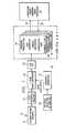
- FIGURE 1is a simple block diagram of a whole receiver according to the prior art.
- a single RF pathamplifies and down-converts the L1 and L2 signal to an intermediate frequency (IF).
- IFintermediate frequency
- the receiverperforms analogue-to-digital conversion before any GPS signal processing takes place.
- the signalis processed in three signal processing chips (SPC).
- SPCsperform all the GPS hardware signal processing.
- receiver 10which utilises antenna 12 feeding into preamp assembly 14.
- Antenna assembly 14feeds into L1/L2 frequency selector 16 which sends signals to L-band down conversion 18.
- Reference oscillator 20 and frequency synthesizer 22provide oscillation for L-band down conversion 18.
- Output from L-band down conversion 18is a second IF that goes into an analog-to-digital converter (A/D) with automatic gain control (AGC) circuit 24.
- A/Danalog-to-digital converter
- AGCautomatic gain control
- the output of this A/D circuitis then channelized to code and carrier wipe off in circuits 26, 28 and 30. This is where the remote signal transmitted by the GPS satellite is compared and matched with the receiver's estimate of the remote signal.
- Signal processing circuits, 26, 28 and 30are shown as signals 32 into processor computer 34.
- Processor computer 34provides signals 36 to signal processing circuit 26, 28 and 30 to direct the circuits to change their code and carrier estimates, as well as for general control of the circuits.
- Each signal processing circuit 26, 28 and 30,uniquely and completely generates carrier estimates, code estimates, base band pre-detection estimates and contains all the correlators for signal processing as well as provides autonomous signal search capability for two satellites.
- Each channelalso has the capability to simultaneously track both the C/A-code and P-code.
- P-codeshall include P(Y)-code.
- FIGURE 2shows how a typical method to perform pre-detection integration in single C/A- and P-code channel 37.
- This channel 20can only track L1 C/A- and P-code or L2 P-code.
- Carrier generator 36generates a complex estimate of the incoming GPS carrier.
- Carrier mixer 38wipes off the incoming carrier.
- P-code clock generator 40 and P-code generator 42generate an estimate of P-code and C/A- code clock generator 44 and C/A-code generator 46 generate an estimate of the C/A-code.
- P-code delay shift register 48 and C/A-code delay shift register 50generate a plurality of P-code and C/A-code phases 1/2-chip apart, respectively.
- codeis wiped off in P-code mixers 52 and C/A-code mixers 54.
- Pre-detection integrationis then performed using an integrate circuit 56.
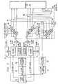
- FIGURE 3describes an enhanced single P-code L1/L2 channel that may be used to enhance the capability of signal processing circuits 26, 28 and 30.
- FIGURE 3shows an enhanced L1/L2 channel 60 according to the present invention.
- the modified P-code clock generator 62generates two P-code clocks with same frequency and independent phase, one for L1 and one for L2.
- the modified P-code clock generator 62also detects which of these clock lead. The leading clock is used to clock P-code generator 64.
- Each new P-code chipis stored in the next location of the P-code circular buffer 302.
- P-code clock generator 62is used to increment the L1 and L2 P-code chip counters 68 and 72, respectively. Whenever the L1 P-code chip counter, 68, is incremented, 16-to-1 MUX 70 passes the next P-code chip stored in the P-code circular buffer 66 to the L1 P-code delay shift register 76.
- the L2 P-code chip counter 72 and 16-to-1 MUX 74are implemented and work in exactly the same manner as the L1 P-code chip counter 68 and 16-to-1 MUX, 70.
- two P-code outputs, one for L1 and one for L2go to code delay shift registers, 76 and 78, respectively.
- P-code generator 64comprises numerous gates and additionally requires significant computer processing capability to support its operation.
- carrier generators for L1 and L2are easy to build and do not consume nearly as much power as would a second complete channel.
- the enhanced L1/L2 channel 60 of FIGURE 3provides maximum operational flexibility with minimal additional circuitry. Circuits which are not changed from the previously described typical C/A- and P-code channel include the P-code generator 64, C/A-code clock generator 44, and C/A-code generator 46.
- the carrier generators, 80 and 82, and carrier mixers, 84 and 86are the same as the previously shown carrier generator 36 and carrier mixer 38, except that L1 carrier generator 80 is also always configured to generate an L1 carrier and the L2 carrier generator 82 is always configured to generate an L2 carrier.
- the code delay shift registers, 76, 78 and 88, code mixers, 90, 92 and 94, the pre-detection integration circuitry 96, and correlator switches 98 and 100are implemented and function such as the code delay shift registers 48 and 50, coder mixers, 52 and 54, the pre-detection integration circuitry 56 and the correlator switches 58 shown in the typical C/A- and P-code channel 37 of FIGURE 2.
- the only differencebeing that there is an extra set of P-code delay shift registers 78, P-code mixers 92 and correlator switches 100 and that the pre-detection integration circuitry 332 supports three additional correlators. This is done to accommodate the extra three correlators required to track L2 P-code.
- a modified P-code clock generator 62Unique to the enhanced channel is a modified P-code clock generator 62, a P-code circular buffer 66, two P-code chip counters, 68 and 72, and two 16-to-1 multiplexers (MUX), 70 and 74.
- MUX16-to-1 multiplexers
- FIGURE 4shows a high level block diagram of the modified P-code clock generator 62.
- This circuitis a unique modification of the low-powered digital oscillator detailed in co-pending application entitled “Method and Systems for a Multi-Channel Global Position System Signal Processor", published as EP0 501 828. Circuitry to determine which clock leads is not shown.
- One approach to determine the leading clockis to extend the P-code chip counters 68 and 74 an extra two bits and compare the counter values to see which clock leads.
- the circuit operation of the modified P-code clock generator 62is basically the same as the code clock generator described in the previously mentioned copending U.S. Patent Applications.
- the modificationis that there are two separate 16-bit P-code clock phase words 112 and 114, one for determining the phase of the L1 P-code clock and the other for determining the phase of the L2 P-code clock. Since initial P-code clock phase only affects the 13 most significant bits of the 32-bit P-code clock generator adder/accumulator, the 19 least significant bits of the adder/accumulator 122 are common to both the L1 and the L2 P-code clock.
- the frequency word 116is also common to both the L1 and L2 P-code clock.
- 112 and 114are two 13-bit adder/accumulators 118 and 120 one for L1 P-code clock and one for L2 P-code clock, which together with the 19-bit adder/accumulator 122 make up two separate 32-bit adder/accumulators capable of generating carriers to the two state machines 124 and 126 with the same frequency but different phase.
- the state machine and carry delay circuits 124 and 126are exactly the same as described in the previously mentioned co-pending U.S. Patent Applications.
- FIGURE 5shows the estimated difference between a typical single L-band channel and the enhanced L1/L2 channel of the present invention.
- An enhanced channelrequires only 42% additional circuitry over a normal channel and provides the performance benefit and software reduction of two completely independent channels for tracking L1 and L2 simultaneously.
- the cost of the enhanced channelis considerably less than the 42% when overhead circuitry such as channel timing and control, processor interface and search specific circuits are included in the gate count estimates. Also note that for this specific example, that the enhanced channel has three additional correlators. This provides approximately a 50% improvement in search speed.
- the enhanced P-code channel of the present inventionthere is provided an apparatus and method for significantly increasing GPS system receiver channel flexibility without a significant increase in circuitry or software complexity.
- the P-Code Channel on-a-chip (PCOAC) to be describedis a dual channel GPS signal processor integrated circuit.
- a 95-pin ceramic pin-grid-array (PGA)contains the 348,300 transistor CMOS gate array.
- Major featuresinclude: two independent GPS channels; a search processor for improved acquisition time; an embedded Y-code generator; system synchronization control; and a 16-bit processor interface.
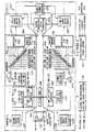
- Figure 6shows a block diagram of PCOAC 1010. Unused functions can be turned off allowing for a high level of power conservation in applications where power usage and/or heat dissipation is an important consideration.
- Each channel of circuit 1010is a dedicated signal processing circnit which de-modulates the code and carrier of a GPS signal and performs pre-detection integration.
- Each channelcontains a code clock generator 1103 (1104), a P and C/A-code generator 1105 (1106), an L1/L2 carrier generator 1109 (1110), eight correlators 1111, 1113, 1115, 1117 (1112, 1114, 1116, 1118) and a noise meter 1119 (1120).
- Each of the eight correlatorscan be selected to operate with C/A-code or P-Code.
- a Y-code generator 1108common to both channels provides independent Y-code for both channels.
- Search processor 1123 and discrete fourier transform (DFT) function 1124improve signal acquisition capability.
- the DFTseparates the sample integration data into seven frequency bins.
- Search processor 1123interpolates between these seven frequency bins to obtains six additional frequency bins, producing a total of thirteen frequency bins per correlator.
- the search processorimplements a Tong detection algorithm on all eight correlators for each of the thirteen frequency bins resulting in the simultaneous search of 1104 search bins per channel.
- PCOAC 1010supports three frequency plans, 57.7920 MHz, 40.9216 MHz and 40.9200 MHz operation.
- Several programmable clocks/interrupts 1130are provided to synchronize the host processor to PCOAC operation.
- Various interrupt schemesare designed to allow trade-offs to be made between system performance, processor throughput requirements and the complexity of the software.
- a standard 16-bit processor interface 1131is utilized.
- integration samplesare buffered 1121 (1122) and the memory map is designed so that block moves are all that is required for channel updates during normal tracking operations.
- Processor Interface Module 1131provides address decode to generate internal read and write strobes, integration sample buffering control, a programmable ring oscillator for test and other miscellaneous functions.
- Digital signal processing circuitry as exemplified hereinmay be implemented by means of a single integrated circuit.
Landscapes
- Engineering & Computer Science (AREA)
- Radar, Positioning & Navigation (AREA)
- Remote Sensing (AREA)
- Computer Networks & Wireless Communication (AREA)
- Physics & Mathematics (AREA)
- General Physics & Mathematics (AREA)
- Position Fixing By Use Of Radio Waves (AREA)
Description
- This invention relates to Global Positioning System (GPS) receivers and more particularly a method for enhancing a single receiver channel for processing a plurality of L-band signals.
- The NAVSTAR Global Positioning System (GPS) is used to determine exact geographic position (i.e. latitude, longitude, and height above the earth) as well as the exact velocity and time of stationary or moving objects. The navigation receiver calculates position, and time by determining distance to a series of satellites. The navigation receiver calculates velocity by determining doppler frequency shift of the satellite signals.
- The NAVSTAR GPS receiver must receive signals generated from the satellite about 11,000 miles away. Each GPS satellite transmits a 6-watt signal. The satellite and receiver, therefore, employs spread spectrum techniques to differentiate the signal from the noise. This is essential since at the antenna the GPS signal is typically about 20 dB below ambient cosmic noise. "Spread spectrum" means that the frequency or instantaneous phase of the signal being transmitted changes as a function of time. Using spread spectrum signal processing techniques, the receiver can track the spread spectrum signal coming from the satellite by estimating a duplicate image of the signal. A precise match of the satellite's spread spectrum signal produces a potential signal processing gain of up to 53 decibels.
- Each satellite generates two spread spectrum signals centered around separate frequencies. The L1 channel is centered about 1575.42 MHz, and has course/acquisition-(C/A-) code and precision- (P-) code modulated on it. C/A-code has a 1.023 MHz chipping rate with a band width of about 2 MHz, and P-code has a 10.23 MHz chipping rate with a bandwidth of about 20 MHz. The L2 channel is centered around 1227.6 MHz and only has P-code modulated on it.
- For some applications it is desirable to track both L1 and L2. A position can be derived from just the C/A- or P-code on the L1 band. However, there is ionospheric delay that unpredictably affects the perceived range to the satellite from the receiver. These errors can be corrected by tracking both L1 and L2 and by measuring the difference in the range that is perceived by the receiver on these L-bands. In this manner, the ionospheric errors can be reduced and the navigation solution can be made more accurate by a few meters. In addition, tracking both L bands simultaneously provides more anti-jamming immunity for operation in hostile environments.
- The easiest way to track L1 and L2 is with an independent tracking loop for each channel. In all implementations to date, either a single channel is multiplexed between L1 and L2 to reduce hardware requirements or an additional complete hardware channel is provided. This either compromises performance and increases software complexity or increases hardware. In either case, this capability adds significant cost to the receiver.
- For some operational scenarios, it may also be desirable to be able to switch between having two independent tracking loops and having one tracking loop with a phase delta between L1 and L2. Two independent loops will be used in hostile environments where there is a good possibility of losing either L1 or L2.
- As an example of the problem, consider the situation of navigating above 80° latitude north. Above 80° latitude, the Northern Lights and sun spot activity in the north pole make the ionosphere so active that there is the need for frequent L1 and L2 calculations to maintain GPS system accuracy. Using present systems, performing these frequent L1 and L2 calculations makes it is necessary to add additional hardware channels to the receiver. This increases space and cost for each receiver, and increases processor throughput and software complexity. Computer resources to support the increased number of hardware channels forces the user to make some performance compromises. If a system existed that can track L1 and L2 without the penalty of additional hardware, increased computer throughout and increased software complexity it would have value for the GPS user community.
- In known systems, it has been necessary to use two channels to track both L1 and L2. The same P-code information is transmitted on the L1 and L2 bands. However, the receiver sees a phase shift between the two signals because of ionospheric influence. The amount of delay is a function of the level of the ionospheric influence. Therefore, if it were possible to use the fact that this information is related, then it may not be necessary to use two wholly independent channels for tracking L1 and L2.
- Accordingly, a need exists in the art for a system and method of tracking both L1 and L2 in a GPS receiver without resorting to two distinct hardware channel receivers or time sharing a single channel.
- A further need exists in the art for such a receiver designed in a way so as to minimise power consumption and size.
- A multi-channel GPS digital signal processor is disclosed in published European application No. 501828 A1. Each channel contains circuitry to process high frequency (L1) band signals and low frequency (L2) band signals of either P-code or C/A-code. The signal processor includes a search processor for fast signal acquisition but does not address problems of power consumption and size.
- A further need exists in the art for a method and system of providing a GPS receiver which allows for both single and double looped processing of L1 and L2 interchangeably. This allows for selection between the high jamming immunity of tracking L1 and L2 independently or the processor throughput savings of tracking L1 and L2 together.
- A GPS receiver is disclosed in published European Application No. 501,829 Al which converts analogue signals to digital signals prior to performing signal acquisition. The receiver includes an A/D converter using full-null-zone processing to increase the anti-jamming capability, but does not address the problem of interchangeably operating single and double looped processing.
- The present invention provides apparatus as defined in each of the appended
claims claim 10. - A technical advantage of the present system is that, by enhancing a single P-code channel, it is possible to obtain the benefit of independent L1 and L2 tracking loops within a GPS system without the penalty of having two independent hardware channels for this purpose.
- Another technical advantage of the present invention is that it possible to gain the benefit of tracking L2 in addition to L1 to reduce error introduced by ionospheric delay, without the additional processor throughput requirements of tracking L2 independently.
- Yet another technical advantage of the present invention is that it permits making continual L1 and L2 calculations without the need for additional computing and support equipment.
- A more complete understanding of the present invention may be acquired by referring to the detailed description and claims when considered in connection with the accompanying drawings in which like reference numerals indicate like features wherein:
- FIGURE 1 is a block diagram of a GPS receiver that may use the enhanced L1/L2 channel of the present invention;
- FIGURE 2 is a block diagram of a typical C/A- and P-code channel for use in a GPS receiver for receiving L1 and L2.
- FIGURE 3 is a block diagram of a preferred embodiment of the enhanced P-code channel for tracking L1 and L2 for GPS applications;
- FIGURE 4 is a block diagram representing the P-code clock generator according to a preferred embodiment of the present invention;
- FIGURE 5 provides a comparison chart between a typical and enhanced P-code channel for tracking L1 and L2 of the present invention.
- Figure 6 shows a block diagram of P-Code Channel on-a-chip (PCOAC) 1010. Unused functions can be turned of allowing for a high level of power conservation in applications where power usage and/or heat dissipation is an important consideration.
- Figure 7 is a block diagram of the top level modules which electrically make up channel A(11) of PCOAC 10:
Base Band Module 1130 generates several global clocks for system synchronization; - The preferred embodiment of the present invention is best understood by referring to the FIGUREs wherein like numbers are used for like corresponding parts of the various components.
- FIGURE 1 is a simple block diagram of a whole receiver according to the prior art. A single RF path amplifies and down-converts the L1 and L2 signal to an intermediate frequency (IF). The receiver performs analogue-to-digital conversion before any GPS signal processing takes place. After the signal is digitised, the signal is processed in three signal processing chips (SPC). The SPCs perform all the GPS hardware signal processing.
- Referring more particularly to FIGURE 1, there is shown
receiver 10 which utilisesantenna 12 feeding intopreamp assembly 14.Antenna assembly 14 feeds into L1/L2 frequency selector 16 which sends signals to L-band downconversion 18. These components all operate under the control ofreference oscillator 20 andfrequency synthesizer 22.Reference oscillator 20 andfrequency synthesizer 22 provide oscillation for L-band downconversion 18. Output from L-band downconversion 18 is a second IF that goes into an analog-to-digital converter (A/D) with automatic gain control (AGC)circuit 24. The output of this A/D circuit is then channelized to code and carrier wipe off incircuits - The outputs of signal processing circuits, 26, 28 and 30 are shown as
signals 32 intoprocessor computer 34.Processor computer 34 providessignals 36 to signalprocessing circuit - Each
signal processing circuit - FIGURE 2 shows how a typical method to perform pre-detection integration in single C/A- and P-
code channel 37. Thischannel 20 can only track L1 C/A- and P-code or L2 P-code.Carrier generator 36 generates a complex estimate of the incoming GPS carrier.Carrier mixer 38 wipes off the incoming carrier. P-code clock generator 40 and P-code generator 42 generate an estimate of P-code and C/A-code clock generator 44 and C/A-code generator 46 generate an estimate of the C/A-code. P-codedelay shift register 48 and C/A-codedelay shift register 50 generate a plurality of P-code and C/A-code phases 1/2-chip apart, respectively. Finally, code is wiped off in P-code mixers 52 and C/A-code mixers 54. Pre-detection integration is then performed using an integratecircuit 56. - Six correlators are shown so the P-code and C/A-code can be track simultaneously (three for P-code and three for C/A-code). In addition, it is possible to dedicate all six correlators to C/A-code using
correlator switches 58 for search modes of operation. This is done so that C/A-code can be found more quickly in typical search operations. - For some applications of GPS, it is desirable to be able to track L1 and L2 simultaneously. Hardware aside, the easiest way to do this is with an independent tracking loop for L1 and L2. By enhancing the previously described
channel 37, it is possible to get the benefit of independent L1 and L2 tracking without the penalty of having two independent channels. For some operational scenarios, it also may be desirable to be able to switch between having two independent tracking loops and having one tracking loop with a phase delta between L1 and L2. Two independent loops would be used in hostile environments where there is a good possibility of losing either L1 or L2. One tracking loop may be desirable for less processor throughout when there is no threat of losing the main L-band. Within a P-code receiver such as that of FIGURE 1, the present invention allows this operational flexibility. For these purposes, FIGURE 3 describes an enhanced single P-code L1/L2 channel that may be used to enhance the capability ofsignal processing circuits - FIGURE 3 shows an enhanced L1/
L2 channel 60 according to the present invention. The modified P-code clock generator 62 generates two P-code clocks with same frequency and independent phase, one for L1 and one for L2. The modified P-code clock generator 62 also detects which of these clock lead. The leading clock is used to clock P-code generator 64. Each new P-code chip is stored in the next location of the P-code circular buffer 302. P-code clock generator 62 is used to increment the L1 and L2 P-code chip counters 68 and 72, respectively. Whenever the L1 P-code chip counter, 68, is incremented, 16-to-1MUX 70 passes the next P-code chip stored in the P-codecircular buffer 66 to the L1 P-codedelay shift register 76. The L2 P-code chip counter 72 and 16-to-1MUX 74 are implemented and work in exactly the same manner as the L1 P-code chip counter 68 and 16-to-1 MUX, 70. Thus, from one P-code generator 64 two P-code outputs, one for L1 and one for L2, go to code delay shift registers, 76 and 78, respectively. This represents a considerable savings in circuitry because P-code generator 64 comprises numerous gates and additionally requires significant computer processing capability to support its operation. Although the preferred embodiment requires a separate carrier generator for each signal frequency, carrier generators for L1 and L2 are easy to build and do not consume nearly as much power as would a second complete channel. - The enhanced L1/
L2 channel 60 of FIGURE 3 provides maximum operational flexibility with minimal additional circuitry. Circuits which are not changed from the previously described typical C/A- and P-code channel include the P-code generator 64, C/A-code clock generator 44, and C/A-code generator 46. The carrier generators, 80 and 82, and carrier mixers, 84 and 86 are the same as the previously showncarrier generator 36 andcarrier mixer 38, except thatL1 carrier generator 80 is also always configured to generate an L1 carrier and theL2 carrier generator 82 is always configured to generate an L2 carrier. Also, the code delay shift registers, 76, 78 and 88, code mixers, 90, 92 and 94, thepre-detection integration circuitry 96, and correlator switches 98 and 100 are implemented and function such as the code delay shift registers 48 and 50, coder mixers, 52 and 54, thepre-detection integration circuitry 56 and the correlator switches 58 shown in the typical C/A- and P-code channel 37 of FIGURE 2. The only difference being that there is an extra set of P-code delay shift registers 78, P-code mixers 92 andcorrelator switches 100 and that the pre-detection integration circuitry 332 supports three additional correlators. This is done to accommodate the extra three correlators required to track L2 P-code. - Unique to the enhanced channel is a modified P-
code clock generator 62, a P-codecircular buffer 66, two P-code chip counters, 68 and 72, and two 16-to-1 multiplexers (MUX), 70 and 74. - FIGURE 4 shows a high level block diagram of the modified P-
code clock generator 62. This circuit is a unique modification of the low-powered digital oscillator detailed in co-pending application entitled "Method and Systems for a Multi-Channel Global Position System Signal Processor", published as EP0 501 828. Circuitry to determine which clock leads is not shown. One approach to determine the leading clock is to extend the P-code chip counters 68 and 74 an extra two bits and compare the counter values to see which clock leads. - The circuit operation of the modified P-
code clock generator 62, is basically the same as the code clock generator described in the previously mentioned copending U.S. Patent Applications. The modification is that there are two separate 16-bit P-codeclock phase words accumulator 122 are common to both the L1 and the L2 P-code clock. Thefrequency word 116 is also common to both the L1 and L2 P-code clock. Along with the two separate P-code clock phase words, 112 and 114 are two 13-bit adder/accumulators accumulator 122 make up two separate 32-bit adder/accumulators capable of generating carriers to the twostate machines delay circuits - FIGURE 5 shows the estimated difference between a typical single L-band channel and the enhanced L1/L2 channel of the present invention. An enhanced channel requires only 42% additional circuitry over a normal channel and provides the performance benefit and software reduction of two completely independent channels for tracking L1 and L2 simultaneously.
- The cost of the enhanced channel is considerably less than the 42% when overhead circuitry such as channel timing and control, processor interface and search specific circuits are included in the gate count estimates. Also note that for this specific example, that the enhanced channel has three additional correlators. This provides approximately a 50% improvement in search speed. As a result of the enhanced P-code channel of the present invention, there is provided an apparatus and method for significantly increasing GPS system receiver channel flexibility without a significant increase in circuitry or software complexity.
- Although this description describes the invention with reference to the above specific embodiments, the claims, and not this description, limit the scope of the invention. Various modifications or the disclosed embodiment, as well as alternative embodiments of the invention, will become apparent to persons skilled in the art upon reference to the above description. Therefore, the appended claims will cover such modification that follow up in the true scope of the invention.
- Aspects of the present invention will be further appreciated from the following:
- The P-Code Channel on-a-chip (PCOAC) to be described is a dual channel GPS signal processor integrated circuit. A 95-pin ceramic pin-grid-array (PGA) contains the 348,300 transistor CMOS gate array. Major features include: two independent GPS channels; a search processor for improved acquisition time; an embedded Y-code generator; system synchronization control; and a 16-bit processor interface.
- Figure 6 shows a block diagram of
PCOAC 1010. Unused functions can be turned off allowing for a high level of power conservation in applications where power usage and/or heat dissipation is an important consideration. - Each channel of
circuit 1010 is a dedicated signal processing circnit which de-modulates the code and carrier of a GPS signal and performs pre-detection integration. Each channel contains a code clock generator 1103 (1104), a P and C/A-code generator 1105 (1106), an L1/L2 carrier generator 1109 (1110), eight correlators 1111, 1113, 1115, 1117 (1112, 1114, 1116, 1118) and a noise meter 1119 (1120). Each of the eight correlators can be selected to operate with C/A-code or P-Code. A Y-code generator 1108 common to both channels provides independent Y-code for both channels. Search processor 1123 and discrete fourier transform (DFT)function 1124 improve signal acquisition capability. The DFT separates the sample integration data into seven frequency bins.Search processor 1123 interpolates between these seven frequency bins to obtains six additional frequency bins, producing a total of thirteen frequency bins per correlator. The search processor implements a Tong detection algorithm on all eight correlators for each of the thirteen frequency bins resulting in the simultaneous search of 1104 search bins per channel.PCOAC 1010 supports three frequency plans, 57.7920 MHz, 40.9216 MHz and 40.9200 MHz operation. Several programmable clocks/interrupts 1130 are provided to synchronize the host processor to PCOAC operation. Various interrupt schemes are designed to allow trade-offs to be made between system performance, processor throughput requirements and the complexity of the software.- A standard 16-
bit processor interface 1131 is utilized. In order to minimize read/write overhead to the PCOAC, integration samples are buffered 1121 (1122) and the memory map is designed so that block moves are all that is required for channel updates during normal tracking operations. - Figure 7 is a block diagram of the top level modules which electrically make up channel A(11) of PCOAC 10:
Base Band Module 1130 generates several global clocks for system synchronization; - Channel Timing Module 1101 generates all clocks and synchronization pulses specific to a single channel;
- Code Generator Module 21 includes a programmable code clock generator, P-code and C/A-code generators/setters, and P-code and C/A-code state advance and retard for search;
- Y-
Code Generator Module 1108 converts the P-code into Y-code for both channels simultaneously even during code state advances; - Front-End Correlator Module 1201 provides L1 or L2 carrier generation, a carrier mixer, a P-code and C/A-code delay shift register (to generate eight code phases), code mixers, data wipe-off, and noise meter signal selection;
- Intermediate Correlator Module 1202 performs the first stage of sample integration for eight complex correlators and a noise meter;
- Back-
End Correlator Module 1203 performs the final stage of sample integration, and also performs noise measurement for aiding in search and tracking (one per channel); - I RAM 1204 and
Q RAM 1205 are two 64 x 16-bit 3-port RAMs per channel for sample integration buffering or to hold intermediate values for DFT calculations; - Discrete Fourier Transfor (DFT)
Module 1124 converts integration samples from all correlators of both channels into seven frequency bins of sample data for search operations; - Search Processor Module 1206 interpolates six additional frequency bins from those provided by the DFT module, performs Tong detection on all thirteen frequency bins of data and retards the code state until a signal is found;
- Search Processor RAM 1207 is a 64 x 16-bit 3-port RAM used by the search processor as a holding register for active Tong counts during search or noise measurement buffering during tracking;
Processor Interface Module 1131 provides address decode to generate internal read and write strobes, integration sample buffering control, a programmable ring oscillator for test and other miscellaneous functions.- Digital signal processing circuitry as exemplified herein may be implemented by means of a single integrated circuit.
Claims (16)
- An enhanced precision code (P-code) channel (60) for use in a GPS receiver, the said channel (60) being capable of simultaneously tracking first and second band signals (L1,L2) and comprising:circuitry (64,66) for generating P-code signals and storing the most recently generated of said P-code signals;a first circuit (68, 70) for selecting and updating first P-code signals having a first phase from said P-code signals, said selected and updated first P-code signals being in-phase with a first code clock associated with the first band signal (L1);a second circuit (72, 74) for selecting and updating second P-code signals having a second phase from said P-code signals, said selected and updated second P-code signals being in-phase with a second code clock associated with the second band signal (L2); anda P-code clock generator (62) for generating said first code clock, the first and second code clocks having the same frequency but different phase;characterised in that:
said P-code clock generator (62) is capable of simultaneously generating the second code clock and said circuitry (64,66) is capable of generating a plurality of P-code signals each having a different phase. - A signal processor for use in a GPS receiver including:
digital signal processing circuitry (26, 28, 30) for acquiring and tracking P-code signals from at least one satellite of a GPS system; and
an enhanced precision code (P-code) channel (60), the said channel (60) being capable of simultaneously tracking first and second band signals (L1,L2) and comprising:circuitry (64,66) for generating P-code signals and storing the most recently generated of said P-code signals;a first circuit (68, 70) for selecting and updating first P-code signals having a first phase from said P-code signals, said selected and updated first P-code signals being in-phase with a first code clock associated with the first band signal (L1);a second circuit (72, 74) for selecting and updating second P-code signals having a second phase from said P-code signals, said selected and updated second P-code signals being in-phase with a second code clock associated with the second band signal (L2); anda P-code clock generator (62) for generating said first code clock, the first and second code clocks having the same frequency but different phase;characterised in that:
said P-code clock generator (62) is capable of simultaneously generating the second code clock and said circuitry (64,66) is capable of generating a plurality of P-code signals each having a different phase. - A receiver (10) for determining the position of at least one satellite of a GPS system, the receiver (10) comprising;
a digital processing circuit (26, 28, 30) for acquiring a signal from the or each one satellite in the presence of noise, and generating an estimate of the current position of the or each satellite based upon data exchanged between the digital signal processing circuit (26, 28, 30) and a signal processor, said signal processor including:
an enhanced precision code (P-code) channel (60), the said channel (60) being capable of simultaneously tracking first and second band signals (L1,L2) and comprising:circuitry (64,66) for generating P-code signals and storing the most recently generated of said P-code signals;a first circuit (68, 70) for selecting and updating first P-code signals having a first phase from said P-code signals, said selected and updated first P-code signals being in-phase with a first code clock associated with the first band signal (L1);a second circuit (72, 74) for selecting and updating second P-code signals having a second phase from said P-code signals, said selected and updated second P-code signals being in-phase with a second code clock associated with the second band signal (L2); anda P-code clock generator (62) for generating said first code clock, the first and second code clocks having the same frequency but different phase;characterised in that:
said P-code clock generator (62) is capable of simultaneously generating the second code clock and said circuitry (64,66) is capable of generating a plurality of P-code signals each having a different phase. - Apparatus according to any one of Claims 1 - 3, characterised in that the apparatus further comprises;
a P-code circular buffer (302) within the generating and storing circuitry (64, 66), the circular buffer (302) being adapted to generate two phases of P-code signal for tracking the first and second band signals (L1, L2). - Apparatus according to any one of Claims 1 - 4, characterised in that the apparatus independently tracks either the first or second band signal (L1, L2).
- Apparatus according to any one of Claims 2 - 5, characterised in that the apparatus further comprises circuitry (44, 46, 62) for simultaneously generating a coarse-acquisition code (C/A code) for the first band signal (L1), the precision-code (P-code) for the first band signal (L1), and the P-code for the second band signal (L2).
- Apparatus according to any one of Claims 2-6, characterised in that the apparatus further comprises circuitry (56, 96, 332) for vector summing said C/A code for the first band signal (L1), the P-code for the first band signal (L1), and the P-code for the second band signal
- Apparatus according to any one of Claims 2 - 7, characterised in that the apparatus further comprises circuitry for continuous ionospheric correction within said channel (60).
- Apparatus according to any one of Claims 2 - 8, characterised in that the or each satellite is a navigational satellite.
- A method for simultaneously tracking first and second band signals (L1, L2) in a P-code channel (60) for use in a GPS receiver, the method comprising:generating P-code signals and storing a plurality of the most recently generated of said P-code signals;selecting and updating first P-code signals having a first phase from the stored plurality of P-code signals in-phase with a first code clock associated with the first band signal (L1);selecting and updating second P-code signals having a second phase from the stored plurality of P-code signals in-phase with a second code clock associated with the second band signal (L2); andgenerating said first P-code clock using a P-code generator (64), the code clocks having the same frequency but different phase,characterised in that said second P-code clock is generated simultaneously with said first P-code clock and in that a plurality of P-code signals are generated each having a different phase.
- The method according to Claim 10, characterised in that the method further comprises ;
tracking the first band signal (L1) in the channel (60) for assisting second band signal (L2) tracking. - The method according to Claim 10, characterised in that the method further comprises;
tracking the second band signal (L2) in the channel (60) for assisting first band signal (L1) tracking. - The method according to any one of Claims 10 - 12, characterised in that the method further comprises;
generating two phases of P-code for tracking the first and second band signals (L1, L2) separately. - The method according to any one of Claims 10 - 12, characterised in that the method further comprises;
independently tracking either the first or second band signal (L1, L2). - The method according to any one of Claims 10 - 14, characterised in that the method further comprises;
simultaneously generating a C/A-code for the first band signal (L1), P-code for the first band signal (L1), and the P-code for the second band signal (L2) within said enhanced P-code channel (60). - The method according to Claim 15, characterised in that the method further comprises;
vector summing said C/A-code for the first band signal (L1), P-code for the first band signal (L1), and the P-code for the second band signal (L2).
Applications Claiming Priority (2)
| Application Number | Priority Date | Filing Date | Title |
|---|---|---|---|
| US677701 | 1991-03-29 | ||
| US07/677,701US5245628A (en) | 1991-03-29 | 1991-03-29 | Enhanced l1/l2 code channel for global positioning system receivers |
Publications (2)
| Publication Number | Publication Date |
|---|---|
| EP0511741A1 EP0511741A1 (en) | 1992-11-04 |
| EP0511741B1true EP0511741B1 (en) | 1997-11-05 |
Family
ID=24719787
Family Applications (1)
| Application Number | Title | Priority Date | Filing Date |
|---|---|---|---|
| EP92302791AExpired - LifetimeEP0511741B1 (en) | 1991-03-29 | 1992-03-30 | Enhanced L1/L2 code channel for global positioning system receivers |
Country Status (3)
| Country | Link |
|---|---|
| US (1) | US5245628A (en) |
| EP (1) | EP0511741B1 (en) |
| DE (1) | DE69222970T2 (en) |
Cited By (35)
| Publication number | Priority date | Publication date | Assignee | Title |
|---|---|---|---|---|
| US6348744B1 (en) | 1998-04-14 | 2002-02-19 | Conexant Systems, Inc. | Integrated power management module |
| US6496145B2 (en) | 1999-03-30 | 2002-12-17 | Sirf Technology, Inc. | Signal detector employing coherent integration |
| US6519277B2 (en) | 1999-05-25 | 2003-02-11 | Sirf Technology, Inc. | Accelerated selection of a base station in a wireless communication system |
| US6526322B1 (en) | 1999-12-16 | 2003-02-25 | Sirf Technology, Inc. | Shared memory architecture in GPS signal processing |
| US6531982B1 (en) | 1997-09-30 | 2003-03-11 | Sirf Technology, Inc. | Field unit for use in a GPS system |
| US6574558B2 (en) | 1996-04-25 | 2003-06-03 | Sirf Technology, Inc. | GPS receiver with cross-track hold |
| US6693953B2 (en) | 1998-09-30 | 2004-02-17 | Skyworks Solutions, Inc. | Adaptive wireless communication receiver |
| US6714158B1 (en) | 2000-04-18 | 2004-03-30 | Sirf Technology, Inc. | Method and system for data detection in a global positioning system satellite receiver |
| US6788655B1 (en) | 2000-04-18 | 2004-09-07 | Sirf Technology, Inc. | Personal communications device with ratio counter |
| US6931233B1 (en) | 2000-08-31 | 2005-08-16 | Sirf Technology, Inc. | GPS RF front end IC with programmable frequency synthesizer for use in wireless phones |
| US6931055B1 (en) | 2000-04-18 | 2005-08-16 | Sirf Technology, Inc. | Signal detector employing a doppler phase correction system |
| US6952440B1 (en) | 2000-04-18 | 2005-10-04 | Sirf Technology, Inc. | Signal detector employing a Doppler phase correction system |
| US7002516B2 (en) | 1999-03-30 | 2006-02-21 | Sirf Technology, Inc. | Signal detector employing correlation analysis of non-uniform and disjoint sample segments |
| US7009555B2 (en) | 2001-04-05 | 2006-03-07 | Sirf Technology, Inc. | GPS-based positioning system for mobile GPS terminals |
| US7183972B2 (en) | 2000-08-24 | 2007-02-27 | Sirf Technology, Inc. | Communications system that reduces auto-correlation or cross-correlation in weak signals |
| US7236883B2 (en) | 2000-08-14 | 2007-06-26 | Sirf Technology, Inc. | Aiding in a satellite positioning system |
| US7365680B2 (en) | 2004-02-10 | 2008-04-29 | Sirf Technology, Inc. | Location services system that reduces auto-correlation or cross-correlation in weak signals |
| US7369830B2 (en) | 2000-07-27 | 2008-05-06 | Sirf Technology, Inc. | Monolithic GPS RF front end integrated circuit |
| US7577448B2 (en) | 2000-08-14 | 2009-08-18 | Sirf Technology Holdings, Inc. | Multi-mode global positioning system for use with wireless networks |
| US7668554B2 (en) | 2001-05-21 | 2010-02-23 | Sirf Technology, Inc. | Network system for aided GPS broadcast positioning |
| US7671489B1 (en) | 2001-01-26 | 2010-03-02 | Sirf Technology, Inc. | Method and apparatus for selectively maintaining circuit power when higher voltages are present |
| US7680178B2 (en) | 2000-08-24 | 2010-03-16 | Sirf Technology, Inc. | Cross-correlation detection and elimination in a receiver |
| US7877104B2 (en) | 2001-05-21 | 2011-01-25 | Sirf Technology Inc. | Method for synchronizing a radio network using end user radio terminals |
| US7929928B2 (en) | 2000-05-18 | 2011-04-19 | Sirf Technology Inc. | Frequency phase correction system |
| US7949362B2 (en) | 2000-05-18 | 2011-05-24 | Sirf Technology, Inc. | Satellite positioning aided communication system selection |
| US7969351B2 (en) | 2001-02-21 | 2011-06-28 | Sirf Technology, Inc. | Mode determination for mobile GPS terminals |
| US7970412B2 (en) | 2000-05-18 | 2011-06-28 | Sirf Technology, Inc. | Aided location communication system |
| US7970411B2 (en) | 2000-05-18 | 2011-06-28 | Sirf Technology, Inc. | Aided location communication system |
| US8013787B2 (en) | 2003-09-02 | 2011-09-06 | Sirf Technology Inc. | Control and features for satellite positioning system receivers |
| US8078189B2 (en) | 2000-08-14 | 2011-12-13 | Sirf Technology, Inc. | System and method for providing location based services over a network |
| US8116976B2 (en) | 2000-05-18 | 2012-02-14 | Csr Technology Inc. | Satellite based positioning method and system for coarse location positioning |
| US8138972B2 (en) | 2003-09-02 | 2012-03-20 | Csr Technology Inc. | Signal processing system for satellite positioning signals |
| US8164517B2 (en) | 2003-09-02 | 2012-04-24 | Csr Technology Inc. | Global positioning system receiver timeline management |
| US8244271B2 (en) | 2001-05-21 | 2012-08-14 | Csr Technology Inc. | Distributed data collection of satellite data |
| US8437693B2 (en) | 2001-05-21 | 2013-05-07 | Csr Technology Inc. | Synchronizing a radio network with end user radio terminals |
Families Citing this family (24)
| Publication number | Priority date | Publication date | Assignee | Title |
|---|---|---|---|---|
| JP2904241B2 (en)* | 1992-07-01 | 1999-06-14 | ケイディディ株式会社 | Transmission method of differential data signal |
| US5535278A (en)* | 1994-05-02 | 1996-07-09 | Magnavox Electronic Systems Company | Global positioning system (GPS) receiver for recovery and tracking of signals modulated with P-code |
| US5736961A (en)* | 1995-10-06 | 1998-04-07 | Novatel, Inc. | Dual Frequency global positioning system |
| US7092369B2 (en) | 1995-11-17 | 2006-08-15 | Symbol Technologies, Inc. | Communications network with wireless gateways for mobile terminal access |
| US5610984A (en)* | 1995-11-22 | 1997-03-11 | Trimble Navigation Limited | Optimal L2 tracking in a SPS receiver under encryption without knowledge of encryption timing characteristics |
| US6393046B1 (en)* | 1996-04-25 | 2002-05-21 | Sirf Technology, Inc. | Spread spectrum receiver with multi-bit correlator |
| US6917644B2 (en) | 1996-04-25 | 2005-07-12 | Sirf Technology, Inc. | Spread spectrum receiver with multi-path correction |
| EP0895599B1 (en)* | 1996-04-25 | 2002-08-07 | Sirf Technology, Inc. | Spread spectrum receiver with multi-bit correlator |
| US6249542B1 (en) | 1997-03-28 | 2001-06-19 | Sirf Technology, Inc. | Multipath processing for GPS receivers |
| JPH11142501A (en)* | 1997-11-13 | 1999-05-28 | Sokkia Co Ltd | GPS receiver |
| US5883597A (en)* | 1997-11-17 | 1999-03-16 | Rockwell International | Frequency translation method and circuit for use in GPS antenna electronics |
| DK0924532T3 (en)* | 1997-11-19 | 2006-07-17 | Imec Vzw | Method and apparatus for receiving GPS / GLONASS signals |
| US6683923B1 (en) | 1999-04-16 | 2004-01-27 | Bd Systems, Inc. | Method and apparatus for detecting and tracking coded signals in a noisy background environment |
| US6278403B1 (en) | 1999-09-17 | 2001-08-21 | Sirf Technology, Inc. | Autonomous hardwired tracking loop coprocessor for GPS and WAAS receiver |
| US6282231B1 (en) | 1999-12-14 | 2001-08-28 | Sirf Technology, Inc. | Strong signal cancellation to enhance processing of weak spread spectrum signal |
| US6671620B1 (en) | 2000-05-18 | 2003-12-30 | Sirf Technology, Inc. | Method and apparatus for determining global position using almanac information |
| US6427120B1 (en) | 2000-08-14 | 2002-07-30 | Sirf Technology, Inc. | Information transfer in a multi-mode global positioning system used with wireless networks |
| US7047023B1 (en) | 2000-12-01 | 2006-05-16 | Sirf Technology, Inc. | GPS RF front end IC with frequency plan for improved integrability |
| US7747236B1 (en) | 2000-12-11 | 2010-06-29 | Sirf Technology, Inc. | Method and apparatus for estimating local oscillator frequency for GPS receivers |
| US7113552B1 (en) | 2000-12-21 | 2006-09-26 | Sirf Technology, Inc. | Phase sampling techniques using amplitude bits for digital receivers |
| US6680703B1 (en) | 2001-02-16 | 2004-01-20 | Sirf Technology, Inc. | Method and apparatus for optimally tuning a circularly polarized patch antenna after installation |
| US7076256B1 (en) | 2001-04-16 | 2006-07-11 | Sirf Technology, Inc. | Method and apparatus for transmitting position data using control channels in wireless networks |
| WO2012003292A1 (en)* | 2010-07-01 | 2012-01-05 | Analysis First LLC | Identification and communication systems |
| US9397397B2 (en)* | 2011-10-03 | 2016-07-19 | Universiteit Twente | Electronically-steered Ku-band phased array antenna comprising an integrated photonic beamformer |
Family Cites Families (9)
| Publication number | Priority date | Publication date | Assignee | Title |
|---|---|---|---|---|
| US4189622A (en)* | 1975-10-17 | 1980-02-19 | Ncr Corporation | Data communication system and bit-timing circuit |
| US4035663A (en)* | 1976-09-01 | 1977-07-12 | Rockwell International Corporation | Two phase clock synchronizing method and apparatus |
| US4468793A (en)* | 1980-12-01 | 1984-08-28 | Texas Instruments Incorporated | Global position system (GPS) multiplexed receiver |
| US4485383A (en)* | 1980-12-01 | 1984-11-27 | Texas Instruments Incorporated | Global position system (GPS) multiplexed receiver |
| US4894662A (en)* | 1982-03-01 | 1990-01-16 | Western Atlas International, Inc. | Method and system for determining position on a moving platform, such as a ship, using signals from GPS satellites |
| US4809005A (en)* | 1982-03-01 | 1989-02-28 | Western Atlas International, Inc. | Multi-antenna gas receiver for seismic survey vessels |
| GB2153177B (en)* | 1984-01-19 | 1987-06-03 | Standard Telephones Cables Ltd | Digital navstar receiver |
| US4821294A (en)* | 1987-07-08 | 1989-04-11 | California Institute Of Technology | Digital signal processor and processing method for GPS receivers |
| US4928106A (en)* | 1988-07-14 | 1990-05-22 | Ashtech Telesis, Inc. | Global positioning system receiver with improved radio frequency and digital processing |
- 1991
- 1991-03-29USUS07/677,701patent/US5245628A/ennot_activeExpired - Lifetime
- 1992
- 1992-03-30EPEP92302791Apatent/EP0511741B1/ennot_activeExpired - Lifetime
- 1992-03-30DEDE69222970Tpatent/DE69222970T2/ennot_activeExpired - Fee Related
Cited By (47)
| Publication number | Priority date | Publication date | Assignee | Title |
|---|---|---|---|---|
| US6574558B2 (en) | 1996-04-25 | 2003-06-03 | Sirf Technology, Inc. | GPS receiver with cross-track hold |
| US6531982B1 (en) | 1997-09-30 | 2003-03-11 | Sirf Technology, Inc. | Field unit for use in a GPS system |
| US6348744B1 (en) | 1998-04-14 | 2002-02-19 | Conexant Systems, Inc. | Integrated power management module |
| US6693953B2 (en) | 1998-09-30 | 2004-02-17 | Skyworks Solutions, Inc. | Adaptive wireless communication receiver |
| US6496145B2 (en) | 1999-03-30 | 2002-12-17 | Sirf Technology, Inc. | Signal detector employing coherent integration |
| US6577271B1 (en) | 1999-03-30 | 2003-06-10 | Sirf Technology, Inc | Signal detector employing coherent integration |
| US7002516B2 (en) | 1999-03-30 | 2006-02-21 | Sirf Technology, Inc. | Signal detector employing correlation analysis of non-uniform and disjoint sample segments |
| US6519277B2 (en) | 1999-05-25 | 2003-02-11 | Sirf Technology, Inc. | Accelerated selection of a base station in a wireless communication system |
| US6930634B2 (en) | 1999-12-16 | 2005-08-16 | Sirf Technology, Inc. | Shared memory architecture in GPS signal processing |
| US6526322B1 (en) | 1999-12-16 | 2003-02-25 | Sirf Technology, Inc. | Shared memory architecture in GPS signal processing |
| US6961660B2 (en) | 2000-04-18 | 2005-11-01 | Sirf Technology, Inc. | Method and system for data detection in a global positioning system satellite receiver |
| US7269511B2 (en) | 2000-04-18 | 2007-09-11 | Sirf Technology, Inc. | Method and system for data detection in a global positioning system satellite receiver |
| US6931055B1 (en) | 2000-04-18 | 2005-08-16 | Sirf Technology, Inc. | Signal detector employing a doppler phase correction system |
| US6952440B1 (en) | 2000-04-18 | 2005-10-04 | Sirf Technology, Inc. | Signal detector employing a Doppler phase correction system |
| US6788655B1 (en) | 2000-04-18 | 2004-09-07 | Sirf Technology, Inc. | Personal communications device with ratio counter |
| US6714158B1 (en) | 2000-04-18 | 2004-03-30 | Sirf Technology, Inc. | Method and system for data detection in a global positioning system satellite receiver |
| US7970412B2 (en) | 2000-05-18 | 2011-06-28 | Sirf Technology, Inc. | Aided location communication system |
| US7929928B2 (en) | 2000-05-18 | 2011-04-19 | Sirf Technology Inc. | Frequency phase correction system |
| US8116976B2 (en) | 2000-05-18 | 2012-02-14 | Csr Technology Inc. | Satellite based positioning method and system for coarse location positioning |
| US7970411B2 (en) | 2000-05-18 | 2011-06-28 | Sirf Technology, Inc. | Aided location communication system |
| US7949362B2 (en) | 2000-05-18 | 2011-05-24 | Sirf Technology, Inc. | Satellite positioning aided communication system selection |
| US8260548B2 (en) | 2000-05-18 | 2012-09-04 | Csr Technology Inc. | Satellite based positioning method and system for coarse location positioning |
| US7369830B2 (en) | 2000-07-27 | 2008-05-06 | Sirf Technology, Inc. | Monolithic GPS RF front end integrated circuit |
| US7577448B2 (en) | 2000-08-14 | 2009-08-18 | Sirf Technology Holdings, Inc. | Multi-mode global positioning system for use with wireless networks |
| US7236883B2 (en) | 2000-08-14 | 2007-06-26 | Sirf Technology, Inc. | Aiding in a satellite positioning system |
| US8078189B2 (en) | 2000-08-14 | 2011-12-13 | Sirf Technology, Inc. | System and method for providing location based services over a network |
| US7724807B2 (en) | 2000-08-24 | 2010-05-25 | Sirf Technology | Method for reducing auto-correlation or cross-correlation in weak signals |
| US7719466B2 (en) | 2000-08-24 | 2010-05-18 | Sirf Technology Holdings, Inc. | Communications systems that reduces auto-correlation or cross-correlation in weak signals |
| US7680178B2 (en) | 2000-08-24 | 2010-03-16 | Sirf Technology, Inc. | Cross-correlation detection and elimination in a receiver |
| US7183972B2 (en) | 2000-08-24 | 2007-02-27 | Sirf Technology, Inc. | Communications system that reduces auto-correlation or cross-correlation in weak signals |
| US6931233B1 (en) | 2000-08-31 | 2005-08-16 | Sirf Technology, Inc. | GPS RF front end IC with programmable frequency synthesizer for use in wireless phones |
| US7512385B2 (en) | 2000-08-31 | 2009-03-31 | Sirf Technology, Inc. | GPS RF front end IC with programmable frequency synthesizer for use in wireless phones |
| US7671489B1 (en) | 2001-01-26 | 2010-03-02 | Sirf Technology, Inc. | Method and apparatus for selectively maintaining circuit power when higher voltages are present |
| US7969351B2 (en) | 2001-02-21 | 2011-06-28 | Sirf Technology, Inc. | Mode determination for mobile GPS terminals |
| US7009555B2 (en) | 2001-04-05 | 2006-03-07 | Sirf Technology, Inc. | GPS-based positioning system for mobile GPS terminals |
| US8164516B2 (en) | 2001-04-05 | 2012-04-24 | Csr Technology Inc. | GPS-based positioning system for mobile GPS terminals |
| US8437693B2 (en) | 2001-05-21 | 2013-05-07 | Csr Technology Inc. | Synchronizing a radio network with end user radio terminals |
| US8244271B2 (en) | 2001-05-21 | 2012-08-14 | Csr Technology Inc. | Distributed data collection of satellite data |
| US7668554B2 (en) | 2001-05-21 | 2010-02-23 | Sirf Technology, Inc. | Network system for aided GPS broadcast positioning |
| US7877104B2 (en) | 2001-05-21 | 2011-01-25 | Sirf Technology Inc. | Method for synchronizing a radio network using end user radio terminals |
| US8138972B2 (en) | 2003-09-02 | 2012-03-20 | Csr Technology Inc. | Signal processing system for satellite positioning signals |
| US8013787B2 (en) | 2003-09-02 | 2011-09-06 | Sirf Technology Inc. | Control and features for satellite positioning system receivers |
| US8164517B2 (en) | 2003-09-02 | 2012-04-24 | Csr Technology Inc. | Global positioning system receiver timeline management |
| US8593345B2 (en) | 2003-09-02 | 2013-11-26 | Csr Technology Inc. | Signal processing system for satellite positioning signals |
| US8947300B2 (en) | 2003-09-02 | 2015-02-03 | Csr Technology Inc. | Control and features for satellite positioning system receivers |
| US7365680B2 (en) | 2004-02-10 | 2008-04-29 | Sirf Technology, Inc. | Location services system that reduces auto-correlation or cross-correlation in weak signals |
| US8810450B2 (en) | 2004-09-02 | 2014-08-19 | Csr Technology Inc. | Global positioning system receiver timeline management |
Also Published As
| Publication number | Publication date |
|---|---|
| DE69222970D1 (en) | 1997-12-11 |
| DE69222970T2 (en) | 1998-03-12 |
| EP0511741A1 (en) | 1992-11-04 |
| US5245628A (en) | 1993-09-14 |
Similar Documents
| Publication | Publication Date | Title |
|---|---|---|
| EP0511741B1 (en) | Enhanced L1/L2 code channel for global positioning system receivers | |
| CA2204585C (en) | A receiver for a navigation system, in particular a satellite navigation system | |
| US7577524B2 (en) | Method and system for data detection in a global positioning system satellite receiver | |
| EP2093584B1 (en) | Processing received satellite radio signals | |
| CA2506700C (en) | Satellite-based positioning system improvement | |
| KR101164749B1 (en) | Gnns receiver and signal tracking circuit and system | |
| US6967992B1 (en) | Method and apparatus for receiving GPS/GLONASS signals | |
| US6191731B1 (en) | GPS receiver having a fast time to first fix | |
| FI106580B (en) | GPS tracking system | |
| US5850420A (en) | Wideband receiver for the measurement of distance by pseudo-random code signals | |
| EP0895601A1 (en) | Improved real-time clock apparatus for fast acquisition of gps signals | |
| US7061972B1 (en) | GPS receiver having dynamic correlator allocation between a memory-enhanced channel for acquisition and standard channels for tracking | |
| FI108580B (en) | Procedure for locating an object, location system, receiver and electronic device | |
| KR20060053188A (en) | A method for determining the position of a radio-frequency signal receiver without knowing an initial schematic position, and a receiver implementing the method. | |
| FI111037B (en) | Electronic device positioning method, determining satellite velocity in relation to electronic device for different satellites, and generating reference data using delta range measurements and velocities | |
| FI110292B (en) | Procedure for determining an error in the comparison time, and electronic device | |
| FI111482B (en) | Positioning method and electronic device | |
| US20030086483A1 (en) | Method and apparatus for spread spectrum signal acquisition | |
| US11815609B2 (en) | System and method for time-of-flight determination using categorization of both code and phase in received signal | |
| JPH04315078A (en) | Gps receiver | |
| US7606328B1 (en) | Common signal generation for an RF receiver | |
| JPS62298787A (en) | GPS position measuring device |
Legal Events
| Date | Code | Title | Description |
|---|---|---|---|
| PUAI | Public reference made under article 153(3) epc to a published international application that has entered the european phase | Free format text:ORIGINAL CODE: 0009012 | |
| AK | Designated contracting states | Kind code of ref document:A1 Designated state(s):DE FR GB IT NL | |
| 17P | Request for examination filed | Effective date:19930420 | |
| 17Q | First examination report despatched | Effective date:19950223 | |
| GRAG | Despatch of communication of intention to grant | Free format text:ORIGINAL CODE: EPIDOS AGRA | |
| GRAH | Despatch of communication of intention to grant a patent | Free format text:ORIGINAL CODE: EPIDOS IGRA | |
| GRAH | Despatch of communication of intention to grant a patent | Free format text:ORIGINAL CODE: EPIDOS IGRA | |
| GRAA | (expected) grant | Free format text:ORIGINAL CODE: 0009210 | |
| AK | Designated contracting states | Kind code of ref document:B1 Designated state(s):DE FR GB IT NL | |
| REF | Corresponds to: | Ref document number:69222970 Country of ref document:DE Date of ref document:19971211 | |
| ITF | It: translation for a ep patent filed | ||
| ET | Fr: translation filed | ||
| PLBE | No opposition filed within time limit | Free format text:ORIGINAL CODE: 0009261 | |
| STAA | Information on the status of an ep patent application or granted ep patent | Free format text:STATUS: NO OPPOSITION FILED WITHIN TIME LIMIT | |
| PG25 | Lapsed in a contracting state [announced via postgrant information from national office to epo] | Ref country code:NL Free format text:LAPSE BECAUSE OF NON-PAYMENT OF DUE FEES Effective date:19981001 | |
| 26N | No opposition filed | ||
| NLV4 | Nl: lapsed or anulled due to non-payment of the annual fee | Effective date:19981001 | |
| REG | Reference to a national code | Ref country code:GB Ref legal event code:IF02 | |
| PGFP | Annual fee paid to national office [announced via postgrant information from national office to epo] | Ref country code:IT Payment date:20070628 Year of fee payment:16 | |
| PGFP | Annual fee paid to national office [announced via postgrant information from national office to epo] | Ref country code:GB Payment date:20080211 Year of fee payment:17 | |
| PGFP | Annual fee paid to national office [announced via postgrant information from national office to epo] | Ref country code:FR Payment date:20080307 Year of fee payment:17 Ref country code:DE Payment date:20080331 Year of fee payment:17 | |
| PG25 | Lapsed in a contracting state [announced via postgrant information from national office to epo] | Ref country code:IT Free format text:LAPSE BECAUSE OF NON-PAYMENT OF DUE FEES Effective date:20080330 | |
| GBPC | Gb: european patent ceased through non-payment of renewal fee | Effective date:20090330 | |
| REG | Reference to a national code | Ref country code:FR Ref legal event code:ST Effective date:20091130 | |
| PG25 | Lapsed in a contracting state [announced via postgrant information from national office to epo] | Ref country code:DE Free format text:LAPSE BECAUSE OF NON-PAYMENT OF DUE FEES Effective date:20091001 | |
| PG25 | Lapsed in a contracting state [announced via postgrant information from national office to epo] | Ref country code:GB Free format text:LAPSE BECAUSE OF NON-PAYMENT OF DUE FEES Effective date:20090330 Ref country code:FR Free format text:LAPSE BECAUSE OF NON-PAYMENT OF DUE FEES Effective date:20091123 |