EP0511599B1 - Gasoline dispenser with vapor recovery system - Google Patents
Gasoline dispenser with vapor recovery systemDownload PDFInfo
- Publication number
- EP0511599B1 EP0511599B1EP92107031AEP92107031AEP0511599B1EP 0511599 B1EP0511599 B1EP 0511599B1EP 92107031 AEP92107031 AEP 92107031AEP 92107031 AEP92107031 AEP 92107031AEP 0511599 B1EP0511599 B1EP 0511599B1
- Authority
- EP
- European Patent Office
- Prior art keywords
- fuel
- vapor
- nozzle
- dispensing
- tank
- Prior art date
- Legal status (The legal status is an assumption and is not a legal conclusion. Google has not performed a legal analysis and makes no representation as to the accuracy of the status listed.)
- Expired - Lifetime
Links
- 239000003502gasolineSubstances0.000titleabstractdescription17
- 238000011084recoveryMethods0.000titledescription2
- 239000000446fuelSubstances0.000claimsabstractdescription101
- 239000002828fuel tankSubstances0.000claimsabstractdescription25
- 238000006073displacement reactionMethods0.000claimsabstractdescription13
- 239000000945fillerSubstances0.000claimsabstractdescription12
- 238000000034methodMethods0.000claimsabstractdescription8
- 239000007788liquidSubstances0.000claimsdescription43
- 238000003860storageMethods0.000claimsdescription28
- 238000005086pumpingMethods0.000claimsdescription6
- 239000012530fluidSubstances0.000claims2
- 239000004215Carbon black (E152)Substances0.000claims1
- 238000004891communicationMethods0.000claims1
- 238000011109contaminationMethods0.000claims1
- 238000007599dischargingMethods0.000claims1
- 229930195733hydrocarbonNatural products0.000claims1
- 150000002430hydrocarbonsChemical class0.000claims1
- 230000008569processEffects0.000abstractdescription3
- 230000009977dual effectEffects0.000description7
- 238000009428plumbingMethods0.000description7
- 230000008901benefitEffects0.000description3
- 238000010586diagramMethods0.000description3
- 230000004044responseEffects0.000description2
- 230000002411adverseEffects0.000description1
- 230000004075alterationEffects0.000description1
- 230000001419dependent effectEffects0.000description1
- 230000000694effectsEffects0.000description1
- 239000008246gaseous mixtureSubstances0.000description1
- 231100001261hazardousToxicity0.000description1
- 230000036541healthEffects0.000description1
- 238000004519manufacturing processMethods0.000description1
- 230000007246mechanismEffects0.000description1
- 239000000203mixtureSubstances0.000description1
- 238000012986modificationMethods0.000description1
- 230000004048modificationEffects0.000description1
- 238000004513sizingMethods0.000description1
- 238000006467substitution reactionMethods0.000description1
Images


Classifications
- B—PERFORMING OPERATIONS; TRANSPORTING
- B67—OPENING, CLOSING OR CLEANING BOTTLES, JARS OR SIMILAR CONTAINERS; LIQUID HANDLING
- B67D—DISPENSING, DELIVERING OR TRANSFERRING LIQUIDS, NOT OTHERWISE PROVIDED FOR
- B67D7/00—Apparatus or devices for transferring liquids from bulk storage containers or reservoirs into vehicles or into portable containers, e.g. for retail sale purposes
- B67D7/04—Apparatus or devices for transferring liquids from bulk storage containers or reservoirs into vehicles or into portable containers, e.g. for retail sale purposes for transferring fuels, lubricants or mixed fuels and lubricants
- B67D7/0476—Vapour recovery systems
- B67D7/0478—Vapour recovery systems constructional features or components
- B67D7/048—Vapour flow control means, e.g. valves, pumps
- B67D7/0482—Vapour flow control means, e.g. valves, pumps using pumps driven at different flow rates
- B67D7/0486—Pumps driven in response to electric signals indicative of pressure, temperature or liquid flow
Definitions
- This inventionrelates to a dispensing system for dispensing volatile liquids according to the pre-characterizing part of claim 1; it relates also to a method of dispensing a single grade and a plurality of grades of liquid fuel according to the pre-characterizing part of claim 9 and 10 respectively.
- each 3785,4 cm 3 (gallon) of gasoline flowing into the fuel tankdisplaces approximately 4916 cm 3 (three hundred cubic inches) of gasoline vapor which, unless collected, escapes into the atmosphere.
- Such vaporsnot only contribute to atmospheric pollution, but also are unpleasant to the person operating the nozzle, and may adversely affect the person's health over a longer term.
- some governmental authoritiesrequire that these vapors be collected.
- Various systemshave been proposed and used for collecting and returning these vapors to a storage vessel, typically the underground storage tank from which the gasoline is being dispensed. The vapors thus stored are then collected for subsequent disposal by the over-the-road tanker when it delivers additional fuel to the storage tank.
- the dispensing pump nozzleis sealed to the filler pipe of the fuel tank so that the displaced vapor is directed by way of an annular conduit around the nozzle and coaxial dual conduit hose and appropriate plumbing to the underground storage tank.
- the design of the nozzle necessary to effect a sealhas generally involved the addition of a bellows around the spout to seal the annular vapor passageway to the filler neck of the tank, as well as various other modifications which make the hand-held nozzle heavy and cumbersome, thereby causing the fueling process to be quite difficult and onerous, particularly for the self-serve motorist.
- GB-A-2 014 544discloses a fuel dispensing system having a vapor recovery subsystem, wherein means for pumping the vapor are operatively coupled with means driven by the fuel flow.
- the volume of vapor being collectedis less than that flowed from the tank, it will obviously result in some vapor escaping into the atmosphere.
- a volume greater than the displaced vaporsis collected, either air may be drawn in with the vapors, which can create a hazardous vapor/air mixture in the storage tank, or a portion of the gasoline dispensed into the tank will be vaporized to make up the difference between the volumetric displacement of the vacuum pump and the vapor displaced by the gasoline added to the fuel tank.
- a jet pumpis driven by one of the submersible pumping units, for example, the regular grade, of the service station to generate a vacuum in a common vapor manifold. While this system does not eliminate the seal required at the nozzle, it does allow use of a less critical seal.
- the disadvantages of this type systemare that whenever a dispenser for a premium grade is turned on, the regular grade submersible pump must be switched on regardless of whether the regular grade is selected or not by the customer. In addition to wasting power, this also tends to generate vapor at the regular grade pump unit. Further, the plumbing required is complex and subject to leaks, and a seal is still required at the nozzle sufficient to prevent air from being drawn into the system because the displacement of the jet pump is not related to the flow of gasoline at the dispensing point.
- US-A-5 038 838discloses a positive displacement pump speed controlled by a motor, which is controlled by a logic unit in relation to the dispensing through a flow meter of fuel to a delivery gun.
- the nozzle of each delivery gunmust have its own vapor collection pump.
- a similar systemis known from DE-U-90 07 190.
- a vapor pumpis controlled by a control signal which is a function of the flow rate of the fuel.
- the referencediscloses only one delivery gun connected to a fuel tank wherein only one single vapor pump is provided. This prior art system cannot easily be extended to a multiplicity of delivering guns.
- US-A-4 273 164discloses a fuel dispensing system having a multiplicity of hand-held nozzles connected to a single storage tank, wherein a valve mechanism is provided between the liquid fuel line and the vapor return line.
- the vapor return lineis subject to a vacuum, which is constant rather than variable. While this dispensing system comprises multiple dispensing stations it requires a single vacuum pump and a proportioning vacuum valve in each dispensing station.
- the present inventionaims to provide a system and a method which eliminate the necessity of a seal between the vapor collection line and the filler neck of the fuel tank, yet providing an economical system for collecting only the correct volume of vapors for the amount of liquid being dispensed, and having progressively increasing econonomic advantage as the system becomes more complex, as is typical for multigrade, multi-lane dispensing systems employed in modern self-service refueling facilities.
- a volatile liquidsuch as gasoline is pumped from a storage tank through a flow meter and dispensed through an on-demand nozzle by the customer into the fuel tank of a vehicle.
- Vapors displaced from the tankare collected through a vacuum intake, preferably disposed concentrically with the nozzle and terminating near the end of the filler neck of the tank; and pumped by an electric motor driven vacuum pump to a vapor storage tank, preferably the fuel storage tank.
- the flow meterproduces an electrical signal representative of the liquid volume flow rate which is used to control the volume of vapor pumped by the vacuum pump so that it is maintained at a preselected ratio with respect to the volume of liquid flowing into the fuel tank.
- a single vacuum pumpis manifolded to collect vapors from a plurality of dispensing nozzles.
- the nozzlescan be part of a multi-grade, single point of sale system, or a combination of each by sizing the vacuum pump and controlling its volumetric rate dependent upon the total volume of liquid fuel being simultaneously dispensed from the nozzles.
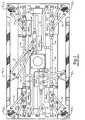
- Figure 1A prior art system is disclosed in Figure 1 which includes a liquid dispensing system of the type referred to above which utilizes hydraulically-driven vacuum pumps to collect vapor and described generally in U.S. Patent No. 4,202,385.
- Figure 1illustrates the plumbing arrangement for such a system which is designed to dispense three grades of fuel from two points of sale, one in each of two traffic lanes.
- the three grades of gasolinewould be dispensed through hoses and associated nozzles attached to hose headers H 1 L 1 , H 2 L 1 and H 3 L 1 to serve a customer's vehicle in lane one.
- Each hose(not illustrated in Figure 1) includes a fuel delivery line and a vapor return line communicating with a hand-held nozzle which includes only a hand-operated fuel valve. Hydraulically-driven vapor pumps HVP 1 L 1 , HVP 2 L 1 and HVP 3 L 1 are provided for the respective hose headers H 1 L 1 , H 2 L 1 and H 3 L 1 of lane one. Fuel lines 12 extend from the respective vapor pumps to the respective hose headers and vapor return lines 14 interconnect the respective headers and vapor pumps.
- a liquid fuel dispensing system in accordance with the present inventionis indicated generally by the reference numeral 30 in Figure 2.
- the system 30illustrates a single-point dispensing system for three different grades of fuel stored in tanks T 1 , T 2 and T 3 .
- a submersed pump P 1delivers fuel from the tank T 1 through a flow meter M 1 and one conduit 31 of a dual-line flexible hose H 1 to a hand-held nozzle unit N 1 .
- fuelis delivered from tank T 2 by pump P 2 through flow meter M 2 and the fuel line 31 of dual conduit hose H 2 to nozzle N 2
- fuelis delivered from tank T 3 by pump P 3 , through flow meter M 3 , dual conduit hose H 3 and hand-held nozzle N 3 .
- Each of the flow meters, M 1 , M 2 and M 3produce an electrical signal indicative of the volume of liquid flowing through the meter to the respective nozzles, which signal is fed to a digital processor 32.
- the digital processorcontinually integrates the flow rate information to calculate the total volume and cost of the fuel as it is being dispensed through the meter activated by the customers use of the respective on-demand nozzle. This information is typically shown to the customer on a display 33 at the point of sale, and may also be displayed to the cashier in a self-service operation.
- Each of the nozzles, N 1 , N 2 and N 3includes a fuel valve 34 and a vacuum valve 35 which are simultaneously operated by a hand actuated lever 36.
- a vacuum intake 37is disposed adjacent a fuel outlet nozzle 38 so as to be partially within the filler neck of the tank, or in such other manner as to effectively capture the vapors displaced from the fuel tank as the gasoline flows into the tank.
- the vacuum intakeis opened to the vacuum return line 39 of the respective hose, H 1 , H 2 or H 3 , and thence to a common vacuum header 44, which in turn is connected to the intake of a positive displacement vacuum pump 46, which is preferably a conventional type pump.
- the output of the vacuum pumpis connected to a vacuum header 48 interconnecting the fuel storage tanks T 1 , T 2 and T 3 .
- the vacuum pump 46is driven by a variable speed electric motor 49. Electrical power for the motor and other electrical components are not illustrated for simplicity.
- the speed of the motor 49is controlled by a suitable speed control circuit 50 which, in turn, is controlled by an output from the digital processor 32.
- a fault sensor 52detects a failure of operation of the vacuum pump and provides an appropriate signal to the digital processor 32 which disables the system from dispensing fuel in the event of a vacuum pump failure.
- the digital processor 32can be a dedicated microprocessor, but in a preferred embodiment of the invention, is the processor which also operates the total service station system and includes the calculation of the volume being delivered to the customer and the cost, which information is displayed at the point of sale by display 33.
- a typical delivery rate of fuel through a selected nozzleis about 37854 cm 3 (ten gallons) per minute, thus requiring about 49160 cm 3 (three thousand cubic inches) per minute displacement for the vacuum pump at a maximum speed of about 1,500 rpm.
- Such a pumptypically requires a two-amp, 120 volt, 50/60 cycle electric motor with a speed range from zero to 1,500 rpm.
- Such a pump and motorcan be manufactured at a relatively low cost.
- the speed control 50is of conventional design, and is responsive to an appropriate signal produced by the digital processor 32 in response to the signal from the active flow meter M 1 , M 2 or M 3 , which typically provides pulses at a rate corresponding to the flow rate through the meter. The rate of these pulses can easily be translated into the appropriate signal to synchronize the pumping rate of the vacuum pump with the flow rate of the gasoline through the meter and maintain a predetermined vapor/gasoline ratio, preferably 1.3:1.0.
- the pumps P 1 , P 2 and P 3provide liquid fuel under pressure to the respective nozzles N 1 , N 2 and N 3 .
- the vacuum intake 37is disposed slightly within the filler neck of the tank.
- both the fuel valve 34 and vacuum valve 35are opened and fuel flows into the customer's tank.
- Fuel flowing through the respective metercauses a signal to be sent to the digital processor 32 which causes the speed control to operate the electric motor at the appropriate rate to collect only the vapors displaced from the fuel tank.
- the vaporsare returned to the fuel storage tanks to replace the liquid fuel being withdrawn.
- Figure 3depicts the system of Figure 2 designed to provide a two-lane unit, indicated generally by the reference numeral 80, capable of dispensing three grades from a single point of sale for each lane, which is the same type unit as disclosed as prior art in Figure 1. Accordingly, the same reference characters are used for the corresponding components H 1 L 1 , H 2 L 1 , H 3 L 1 and H 1 L 2 , H 2 L 2 and H 3 L 2 .
- the hose manifolds H 1 L 1 , H 2 L 1 , and H 3 L 1are the swivel connections for the dual conduit hoses H 1 , H 2 and H 3 for the system 30 of Figure 2.
- the vapor manifold 44collects the vapors from the three hoses and directs it to the intake of vacuum pump 46, the output of which is fed to the storage tank manifold 48.
- Fuel lines 40, 41, and 42extend to the respective hoses H 1 , H 2 and H 3 for lane one.
- the speed controller 50controls the motor 49 which drives the vacuum pump.
- a duplicate set of parts to that just describedis associated with hoses H 1 L 2 , H 2 L 2 and H 3 L 2 for service lane two and are designated by corresponding reference characters. From a comparison of Figures 1 and 3, it will be appreciated that the system of the present invention shown in Figure 3 is substantially less complex and less expensive to fabricate than the prior art system shown in Figure 1. The more complex the system, the greater the cost savings of the present invention.
- FIG. 1Another embodiment of the present invention is indicated generally by the reference numeral 100 in Figure 4.
- This systemis similar to the single point of sale, multiple grade system 30 of Figure 2, but is designed to provide a plurality of points of sale of a single grade of fuel. Where applicable, the same reference characters are used to designate the same component parts.
- the system 100includes a single fuel tank T having a submersed pump P which pressurizes a fuel manifold 102.
- the manifold 102provides fuel to three flow meters M 1 , M 2 and M 3 which measure the flow rate of fuel being fed through concentric, dual conduit, flexible hoses H 1 , H 2 and H 3 to nozzles N 1 , N 2 and N 3 , each having both a fuel valve and vacuum valve, all of which may be substantially as heretofore described in connection with the system 30 of Figure 2.
- the electrical signals representing volume flow rate information from the meters M 1 , M 2 and M 3are each fed to a digital processor 104 which, in turn, provides point of sale volume and cost information to displays D 1 , D 2 and D 3 associated with the fuel dispensed through the respective nozzles N 1 , N 2 and N 3 .
- a vapor collection manifold 106is connected to the intake of a vapor vacuum pump 108, the output of which is connected back to the storage tank T by conduit 110.
- the vapor pumpis driven by an electric motor 112, the speed of which is controlled by speed controller 114.
- the vapor collection system 100is thus very similar to that illustrated in Figure 2 except that the vapor pump 108 must have a capacity adequate to handle the total vapor collections from all of the nozzles N 1 , N 2 and N 3 when fuel is being dispensed from all of the nozzles simultaneously.
- the digital processor 104provides an output to the speed controller 114 which is the sum of the total flow rates through meters M 1 , M 2 and M 3 .
- the manifold 106is designed such that the resistance to vapor flow through the respective hoses H 1 , H 2 and H 3 and manifold are essentially equal.
- the manually-operated vapor control valves, and the respective fuel valvesare metering valves so that vapor is metered in by partially open vapor valves in the same proportion as fuel is metered out by a partially open fuel valve.
- the vacuum pump 108is operated at a capacity sufficient to provide a total vapor displacement volume appropriate for the total liquid volume being dispensed through all the nozzles.
- Operating the proportioning valves in the vapor lines in synchronism with the respective fuel valvesresult in the appropriate amount of vapor being withdrawn from each of the respective fuel tanks being filled. It will, of course, be appreciated that the system of Figure 4 is applicable for one, or any number of dispensing nozzles.
- the vacuum pump means 46 and 49can alternatively be a constant speed electric motor with a variable volume vacuum pump responding to the electrical signal from the digital processor. It will also be appreciated that a dedicated digital processor, or other electrical system can be used to control the volume throughput of the vacuum pump in response to the measured liquid flow rate.
Landscapes
- Physics & Mathematics (AREA)
- Fluid Mechanics (AREA)
- Engineering & Computer Science (AREA)
- Mechanical Engineering (AREA)
- Loading And Unloading Of Fuel Tanks Or Ships (AREA)
- Vaporization, Distillation, Condensation, Sublimation, And Cold Traps (AREA)
Abstract
Description
- This invention relates to a dispensing system for dispensing volatile liquids according to the pre-characterizing part of claim 1; it relates also to a method of dispensing a single grade and a plurality of grades of liquid fuel according to the pre-characterizing part of
claim 9 and 10 respectively. - As an automobile is being refueled with gasoline at a service station, each 3785,4 cm3 (gallon) of gasoline flowing into the fuel tank displaces approximately 4916 cm3 (three hundred cubic inches) of gasoline vapor which, unless collected, escapes into the atmosphere. Such vapors not only contribute to atmospheric pollution, but also are unpleasant to the person operating the nozzle, and may adversely affect the person's health over a longer term. As a result, some governmental authorities require that these vapors be collected. Various systems have been proposed and used for collecting and returning these vapors to a storage vessel, typically the underground storage tank from which the gasoline is being dispensed. The vapors thus stored are then collected for subsequent disposal by the over-the-road tanker when it delivers additional fuel to the storage tank.
- In one such system, the dispensing pump nozzle is sealed to the filler pipe of the fuel tank so that the displaced vapor is directed by way of an annular conduit around the nozzle and coaxial dual conduit hose and appropriate plumbing to the underground storage tank. The design of the nozzle necessary to effect a seal has generally involved the addition of a bellows around the spout to seal the annular vapor passageway to the filler neck of the tank, as well as various other modifications which make the hand-held nozzle heavy and cumbersome, thereby causing the fueling process to be quite difficult and onerous, particularly for the self-serve motorist. GB-A-2 014 544 discloses a fuel dispensing system having a vapor recovery subsystem, wherein means for pumping the vapor are operatively coupled with means driven by the fuel flow.
- The problems relating to the design of the nozzle has been mitigated to a large extent by a system which utilizes a vacuum pump to assist the collection of vapor and transfer it to the storage tank. As a result of the use of the vacuum pump, it is unnecessary to seal the vapor line to the filler neck of the tank by the bellows, hence reducing the weight of the nozzle and simplifying the fueling process. In this type system, the vacuum inlet for the vapors need only be placed in close proximity to the filler neck of the tank. However, it is very important in this system that the rate of gaseous mixtures drawn in through the vacuum inlet closely approximate the volume of vapor being displaced by the gasoline flowing into the tank. If the volume of vapor being collected is less than that flowed from the tank, it will obviously result in some vapor escaping into the atmosphere. On the other hand, if a volume greater than the displaced vapors is collected, either air may be drawn in with the vapors, which can create a hazardous vapor/air mixture in the storage tank, or a portion of the gasoline dispensed into the tank will be vaporized to make up the difference between the volumetric displacement of the vacuum pump and the vapor displaced by the gasoline added to the fuel tank.
- The systems previously developed which utilized this system achieved the control of the appropriate ratio of vapor to liquid dispensed by driving a positive displacement vacuum pump with a hydraulic motor driven by the flow of gasoline being dispensed to the tank. A major disadvantage of this type system (hereafter discussed in detail in connection with Figure 2) is the requirement that there be a hydraulically-driven vacuum pump for each dispensing hose or nozzle; and each pump unit is relatively expensive to manufacture. In addition, the large number of individual nozzles associated with each typical multi-grade dispensing unit results not only in complex and expensive plumbing, but also occupies substantial space. Thus, the total cost of the system is a deterrent to its widespread adoption.
- In another type system, a jet pump is driven by one of the submersible pumping units, for example, the regular grade, of the service station to generate a vacuum in a common vapor manifold. While this system does not eliminate the seal required at the nozzle, it does allow use of a less critical seal. The disadvantages of this type system are that whenever a dispenser for a premium grade is turned on, the regular grade submersible pump must be switched on regardless of whether the regular grade is selected or not by the customer. In addition to wasting power, this also tends to generate vapor at the regular grade pump unit. Further, the plumbing required is complex and subject to leaks, and a seal is still required at the nozzle sufficient to prevent air from being drawn into the system because the displacement of the jet pump is not related to the flow of gasoline at the dispensing point.
- US-A-5 038 838 discloses a positive displacement pump speed controlled by a motor, which is controlled by a logic unit in relation to the dispensing through a flow meter of fuel to a delivery gun. The nozzle of each delivery gun must have its own vapor collection pump. A similar system is known from DE-U-90 07 190. A vapor pump is controlled by a control signal which is a function of the flow rate of the fuel. The reference discloses only one delivery gun connected to a fuel tank wherein only one single vapor pump is provided. This prior art system cannot easily be extended to a multiplicity of delivering guns.
- US-A-4 273 164 discloses a fuel dispensing system having a multiplicity of hand-held nozzles connected to a single storage tank, wherein a valve mechanism is provided between the liquid fuel line and the vapor return line. The vapor return line is subject to a vacuum, which is constant rather than variable. While this dispensing system comprises multiple dispensing stations it requires a single vacuum pump and a proportioning vacuum valve in each dispensing station.
- The present invention aims to provide a system and a method which eliminate the necessity of a seal between the vapor collection line and the filler neck of the fuel tank, yet providing an economical system for collecting only the correct volume of vapors for the amount of liquid being dispensed, and having progressively increasing econonomic advantage as the system becomes more complex, as is typical for multigrade, multi-lane dispensing systems employed in modern self-service refueling facilities.
- This is achieved by the features of claim 1 and claims 9, 10, respectively.
- In accordance with the present invention, a volatile liquid such as gasoline is pumped from a storage tank through a flow meter and dispensed through an on-demand nozzle by the customer into the fuel tank of a vehicle. Vapors displaced from the tank are collected through a vacuum intake, preferably disposed concentrically with the nozzle and terminating near the end of the filler neck of the tank; and pumped by an electric motor driven vacuum pump to a vapor storage tank, preferably the fuel storage tank. The flow meter produces an electrical signal representative of the liquid volume flow rate which is used to control the volume of vapor pumped by the vacuum pump so that it is maintained at a preselected ratio with respect to the volume of liquid flowing into the fuel tank.
- In accordance with the invention, a single vacuum pump is manifolded to collect vapors from a plurality of dispensing nozzles. The nozzles can be part of a multi-grade, single point of sale system, or a combination of each by sizing the vacuum pump and controlling its volumetric rate dependent upon the total volume of liquid fuel being simultaneously dispensed from the nozzles.
- These and other objects, features and advantages of the invention will be apparent to those skilled in the art from the following description of the preferred embodiment taken together with the accompanied drawings in which:
- Figure 1 is a plan view of the typical plumbing layout of a prior art liquid dispensing system;
- Figure 2 is a schematic diagram which serves to illustrate a preferred embodiment of a liquid dispensing system in accordance with the present invention;
- Figure 3 is a plan view of a plumbing diagram illustrating the liquid dispensing system of Figure 2 as compared to the prior art system of Figure 1; and,
- Figure 4 is a schematic diagram of an alternative liquid dispensing system in accordance with the present invention.
- A prior art system is disclosed in Figure 1 which includes a liquid dispensing system of the type referred to above which utilizes hydraulically-driven vacuum pumps to collect vapor and described generally in U.S. Patent No. 4,202,385. Figure 1 illustrates the plumbing arrangement for such a system which is designed to dispense three grades of fuel from two points of sale, one in each of two traffic lanes. Thus, the three grades of gasoline would be dispensed through hoses and associated nozzles attached to hose headers H1L1, H2L1 and H3L1 to serve a customer's vehicle in lane one. Similarly, three hoses would be attached to hose headers H1L2, H2L2 and H3L2 to dispense three grades of fuel to a vehicle in lane two. Each hose (not illustrated in Figure 1) includes a fuel delivery line and a vapor return line communicating with a hand-held nozzle which includes only a hand-operated fuel valve. Hydraulically-driven vapor pumps HVP1L1, HVP2L1 and HVP3L1 are provided for the respective hose headers H1L1, H2L1 and H3L1 of lane one.
Fuel lines 12 extend from the respective vapor pumps to the respective hose headers andvapor return lines 14 interconnect the respective headers and vapor pumps. After passing through a flow meter, fuel under pressure is delivered to the respective hydraulic motors of the vapor pumps bylines 10, and the vapor is output from the vacuum pumps to acommon vapor header 16, which returns vapor to the separate fuel storage tanks (not illustrated) for the three grades of fuel. The tanks are interconnected by a common vapor header in the conventional manner. Thus, it will be seen that for a dual lane, dual point of sale dispenser for three grades of fuel, a total of six hydraulically-driven vapor pumps HVP are required together with all of the associated plumbing illustrated. Each HVP pump collects a volume of gas (vapor) which is 1.3 times as great as the equivalent volume of liquid gasoline passing through the hydraulic motor complex to drive the vacuum pump. - A liquid fuel dispensing system in accordance with the present invention is indicated generally by the
reference numeral 30 in Figure 2. Thesystem 30 illustrates a single-point dispensing system for three different grades of fuel stored in tanks T1, T2 and T3. A submersed pump P1 delivers fuel from the tank T1 through a flow meter M1 and oneconduit 31 of a dual-line flexible hose H1 to a hand-held nozzle unit N1. Similarly, fuel is delivered from tank T2 by pump P2 through flow meter M2 and thefuel line 31 of dual conduit hose H2 to nozzle N2, and fuel is delivered from tank T3 by pump P3, through flow meter M3, dual conduit hose H3 and hand-held nozzle N3. - Each of the flow meters, M1, M2 and M3, produce an electrical signal indicative of the volume of liquid flowing through the meter to the respective nozzles, which signal is fed to a
digital processor 32. The digital processor continually integrates the flow rate information to calculate the total volume and cost of the fuel as it is being dispensed through the meter activated by the customers use of the respective on-demand nozzle. This information is typically shown to the customer on adisplay 33 at the point of sale, and may also be displayed to the cashier in a self-service operation. - Each of the nozzles, N1, N2 and N3, includes a
fuel valve 34 and avacuum valve 35 which are simultaneously operated by a hand actuatedlever 36. Avacuum intake 37 is disposed adjacent afuel outlet nozzle 38 so as to be partially within the filler neck of the tank, or in such other manner as to effectively capture the vapors displaced from the fuel tank as the gasoline flows into the tank. When thevalves lever 36, the vacuum intake is opened to thevacuum return line 39 of the respective hose, H1, H2 or H3, and thence to acommon vacuum header 44, which in turn is connected to the intake of a positivedisplacement vacuum pump 46, which is preferably a conventional type pump. The output of the vacuum pump is connected to avacuum header 48 interconnecting the fuel storage tanks T1, T2 and T3. - The
vacuum pump 46 is driven by a variable speedelectric motor 49. Electrical power for the motor and other electrical components are not illustrated for simplicity. The speed of themotor 49 is controlled by a suitablespeed control circuit 50 which, in turn, is controlled by an output from thedigital processor 32. Afault sensor 52 detects a failure of operation of the vacuum pump and provides an appropriate signal to thedigital processor 32 which disables the system from dispensing fuel in the event of a vacuum pump failure. Thedigital processor 32 can be a dedicated microprocessor, but in a preferred embodiment of the invention, is the processor which also operates the total service station system and includes the calculation of the volume being delivered to the customer and the cost, which information is displayed at the point of sale bydisplay 33. - A typical delivery rate of fuel through a selected nozzle is about 37854 cm3 (ten gallons) per minute, thus requiring about 49160 cm3 (three thousand cubic inches) per minute displacement for the vacuum pump at a maximum speed of about 1,500 rpm. Such a pump typically requires a two-amp, 120 volt, 50/60 cycle electric motor with a speed range from zero to 1,500 rpm. Such a pump and motor can be manufactured at a relatively low cost. The
speed control 50 is of conventional design, and is responsive to an appropriate signal produced by thedigital processor 32 in response to the signal from the active flow meter M1, M2 or M3, which typically provides pulses at a rate corresponding to the flow rate through the meter. The rate of these pulses can easily be translated into the appropriate signal to synchronize the pumping rate of the vacuum pump with the flow rate of the gasoline through the meter and maintain a predetermined vapor/gasoline ratio, preferably 1.3:1.0. - In the operation of the
system 30 of Figure 2, the pumps P1, P2 and P3 provide liquid fuel under pressure to the respective nozzles N1, N2 and N3. When a customer selects a grade of fuel and inserts the selectednozzle 38 in the neck of the tank, thevacuum intake 37 is disposed slightly within the filler neck of the tank. When the customer activates the nozzle lever, both thefuel valve 34 andvacuum valve 35 are opened and fuel flows into the customer's tank. Fuel flowing through the respective meter causes a signal to be sent to thedigital processor 32 which causes the speed control to operate the electric motor at the appropriate rate to collect only the vapors displaced from the fuel tank. The vapors are returned to the fuel storage tanks to replace the liquid fuel being withdrawn. - The advantages of the system of Figure 2 compared to the prior art device of Figure 1 are readily apparent from Figure 3. Figure 3 depicts the system of Figure 2 designed to provide a two-lane unit, indicated generally by the
reference numeral 80, capable of dispensing three grades from a single point of sale for each lane, which is the same type unit as disclosed as prior art in Figure 1. Accordingly, the same reference characters are used for the corresponding components H1L1, H2L1, H3L1 and H1L2, H2L2 and H3L2. The hose manifolds H1L1, H2L1, and H3L1 are the swivel connections for the dual conduit hoses H1, H2 and H3 for thesystem 30 of Figure 2. Thevapor manifold 44 collects the vapors from the three hoses and directs it to the intake ofvacuum pump 46, the output of which is fed to thestorage tank manifold 48. Fuel lines 40, 41, and 42 extend to the respective hoses H1, H2 and H3 for lane one. Thespeed controller 50 controls themotor 49 which drives the vacuum pump. A duplicate set of parts to that just described is associated with hoses H1L2, H2L2 and H3L2 for service lane two and are designated by corresponding reference characters. From a comparison of Figures 1 and 3, it will be appreciated that the system of the present invention shown in Figure 3 is substantially less complex and less expensive to fabricate than the prior art system shown in Figure 1. The more complex the system, the greater the cost savings of the present invention. - Another embodiment of the present invention is indicated generally by the reference numeral 100 in Figure 4. This system is similar to the single point of sale,
multiple grade system 30 of Figure 2, but is designed to provide a plurality of points of sale of a single grade of fuel. Where applicable, the same reference characters are used to designate the same component parts. The system 100 includes a single fuel tank T having a submersed pump P which pressurizes afuel manifold 102. The manifold 102 provides fuel to three flow meters M1, M2 and M3 which measure the flow rate of fuel being fed through concentric, dual conduit, flexible hoses H1, H2 and H3 to nozzles N1, N2 and N3, each having both a fuel valve and vacuum valve, all of which may be substantially as heretofore described in connection with thesystem 30 of Figure 2. However, the electrical signals representing volume flow rate information from the meters M1, M2 and M3 are each fed to adigital processor 104 which, in turn, provides point of sale volume and cost information to displays D1, D2 and D3 associated with the fuel dispensed through the respective nozzles N1, N2 and N3. Avapor collection manifold 106 is connected to the intake of avapor vacuum pump 108, the output of which is connected back to the storage tank T byconduit 110. The vapor pump is driven by anelectric motor 112, the speed of which is controlled byspeed controller 114. - The vapor collection system 100 is thus very similar to that illustrated in Figure 2 except that the
vapor pump 108 must have a capacity adequate to handle the total vapor collections from all of the nozzles N1, N2 and N3 when fuel is being dispensed from all of the nozzles simultaneously. As a consequence, thedigital processor 104 provides an output to thespeed controller 114 which is the sum of the total flow rates through meters M1, M2 and M3. Also, the manifold 106 is designed such that the resistance to vapor flow through the respective hoses H1, H2 and H3 and manifold are essentially equal. Further, the manually-operated vapor control valves, and the respective fuel valves are metering valves so that vapor is metered in by partially open vapor valves in the same proportion as fuel is metered out by a partially open fuel valve. Thus, thevacuum pump 108 is operated at a capacity sufficient to provide a total vapor displacement volume appropriate for the total liquid volume being dispensed through all the nozzles. Operating the proportioning valves in the vapor lines in synchronism with the respective fuel valves result in the appropriate amount of vapor being withdrawn from each of the respective fuel tanks being filled. It will, of course, be appreciated that the system of Figure 4 is applicable for one, or any number of dispensing nozzles. - It will be appreciated that the vacuum pump means 46 and 49 can alternatively be a constant speed electric motor with a variable volume vacuum pump responding to the electrical signal from the digital processor. It will also be appreciated that a dedicated digital processor, or other electrical system can be used to control the volume throughput of the vacuum pump in response to the measured liquid flow rate.
- Although preferred embodiments of the invention have been described in detail, it is to be understood that various changes, substitutions and alterations can be made therein without departing from the scope of the invention as defined by the appended claims.
Claims (11)
- A dispensing system for dispensing volatile liquids such as hydrocarbon fluids for vehicles while collecting the vapors to reduce atmospheric pollution, the system having a plurality of liquid dispensing means each comprising a hand-held nozzle (N1, N2, N3) and liquid valve means (34) disposed at the end of a flexible fuel hose (31) for flowing liquid into the fuel tank of a vehicle under control of an operator, vapor intake means (37) positioned with each nozzle comprising the open end portion of a vacuum suction hose (39) for each nozzle, leading along with the associated fuel hose for each nozzle, to a point of sale fuel dispenser, a fuel storage tank (T) having a fuel pump (P) fluidly coupled through a fuel flow meter device (M1, M2, M3) and a flexible fuel line to the flexible fuel hose of one of said plurality of liquid dispensing means, vapor suction means coupled on the intake side through a line (44, 106) to the vacuum suction hose (39) of each nozzle, comprising positive displacement vacuum pump means having its output side fluidly coupled to a vapor manifold (48, 110) leading to the fuel storage tank (T), and an electric control unit receiving signals from each fuel flow meter device (M1, M2, M3) which are used to control the output of the vacuum pump means in order to match the volume of vapor collected from the vapor intake means (37) of a given hand-held nozzle with the volume of fuel being pumped through that nozzle in order to substantially replace the volume of liquid fuel being pumped through that nozzle in order to substantially replace the volume of liquid fuel removed from the fuel storage tank and delivered through said nozzle with the vapor collected from the fueling operation at said nozzle, the improvement characterized in that:the vapor suction means is a single positive displacement vacuum pump (46, 108) for the plurality of hand-held nozzles (38, N1 - N3);the input side of the vacuum pump (46, 108) is connected to a common vacuum header (44, 106);the vacuum suction hoses (39, H1 - H3) of said plurality of hand-held nozzles are each connected in fluid communication with said common vacuum header (44, 106);each of said nozzles includes a manual vacuum valve (35, N1 - N3) for the vacuum suction hoses which is opened when fuel is dispensing from said nozzle into a vehicle fuel tank and closed when said dispensing ceases; andsaid control unit (32, 104) is a common control unit for the plurality of hand-held nozzles, which adjusts the positive displacement vacuum pump (46, 108) to produce a volumetric rate of vapor collection from the common vacuum header having a predetermined relationship to the volumetric rate at which fuel is being dispensed from a given one of said plurality of nozzles so that vapor removal always matches the fuel being dispensed in order to avoid atmospheric contamination at a fueling station.
- The dispensing system of Claim 1 further characterized in that:the manual vacuum valve (35, N1- N3) in each of said nozzles is a metering valve so that vapor is metered in by the partially open metering valve in the same proportion as fuel is metered out by said partially open liquid valve means (34) in said nozzles.
- The dispensing system of one of Claims 1 or 2 characterized in that the vapors are collected by said vapor intake (37) disposed in close proximity but not sealed to the filler neck of the vehicle tank.
- The dispensing system of any of claims 1 - 3 further characterized by:a plurality of fuel storage tanks (T1, T2, T3) each having a fuel pump (P1, P2, P3) fluidly coupled through a line (31) to one of the flexible fuel hoses through a flow meter device (M1, M2, M3) for each hand-held nozzle (N1, N2, N3),
wherein the vapor manifold (48, 110) is coupled to said fuel tanks to return vapor collected by any of the nozzles to said tanks. - The dispensing system of one of Claims 1 - 4 characterized in that the electrical control unit (32, 104) includes a point of sale display (33, D1, D2, D3) indicating the volume and cost of the fuel being dispensed.
- The dispensing system of one of Claims 1 - 5 further characterized in that each fuel flow meter (M1, M2, M3) produces a first electrical signal representative of the rate of flow of fuel being dispensed from ones of the respective nozzles; andthe control unit (32, 104) comprises digital processing means of receiving each of the first electrical signals and operating the vacuum pump (46, 108) whereby substantially all fuel vapor will be delivered to the vapor manifold (48, 106) leading to one or more fuel storage tanks.
- The dispensing system of any one of Claims 1 - 6 characterized in that the system includes a fault sensor (52) which detects a failure of operation of the vacuum pump (46, 108) and provides an appropriate signal to the electrical control unit (32, 104) which disables the system from dispensing fuel in the event of a vacuum pump failure.
- The dispensing system of any one of Claims 1 - 7 characterized in that said manual vacuum valve (35) and said liquid valve means (34) of each nozzle are simultaneously operated by a hand-operated lever (36).
- The method of dispensing a single grade of liquid fuel from a system having a single storage tank (T) pumping fuel to a plurality of hand-held nozzles (N1, N2, N3), each disposed at a separate point of sale, into a customer's fuel tank having a filler neck, the system having liquid valve means (34) and vapor intake means (37) at each nozzle, comprising the open end portion of a vacuum suction hose (39) leading to vapor suction means connected to said tank (T), flow meters (M1, M2, M3) between a fuel pump and the liquid valve means (34) producing signals representative of flow of fuel which are processed by an electrical control unit (104) which operates the vapor suction means to remove vapor from vapor intake means (37) at a rate sufficient to substantially replace the volume of liquid fuel dispensed through the nozzles and deliver the collected vapor to the storage tank, characterized by the steps of:providing a vapor suction means comprising a single positive displacement vacuum pump (108) connected through a manifold (106) to the plurality of nozzles (N1, N2, N3);providing a manual valve (35) comprised of a metering valve at each nozzle vapor intake means (37) which is opened when fuel is dispensing from said nozzle into a vehicle fuel tank and closed when said dispensing ceases;simultaneously opening the liquid valve means (34) and manual vacuum valve (35) associated with the respective nozzles on demand from one or more customers;pumping fuel from the storage tank and producing signals representative of the volume of fuel passing through each respective flow meter (M1, M2, M3) and nozzle (N1, N2, N3);maintaining the degree of the opening of the vacuum valve (35) in predetermined relationship to the degree of opening of the liquid valve means (34) whereby the fuel vapors collected at each vehicle fuel tank is maintained proportional to the liquid fuel dispensed; anddigitally processing said signals from all of said flowmeters (M1, M2, M3) and operating said single vacuum pump (108) to collect vapor displaced from all of the fuel tanks to which fuel is being dispensed, at a vapor volume flow rate related in a predetermined manner to the total flow rate of fuel to all of the vehicle fuel tanks.
- The method of dispensing a plurality of grades of liquid fuels from a system having a plurality of liquid storage tanks (T1, T2, T3) through a plurality of hand-held nozzles (N1, N2, N3), into a customer's fuel tank having a filler neck, the system having liquid valve means (34) and vapor intake means (37) at each nozzle, comprising the open end portion of a vacuum suction hose (39) leading to vapor suction means connected to said storage tanks (T1, T2, T3); flow meters (M1, M2, M3) between fuel pumps (P1, P2, P3) for each tank and the liquid valve means (34), the flow meters producing signals representative of the flow of fuel being processed to an electrical control unit (32) which operates the vapor suction means to remove vapor from the vapor intake means (37) at a rate sufficient to substantially replace the volume of liquid fuel dispensed through said nozzles and delivering the collected vapor to the storage tanks, characterized by the steps of:providing a vapor suction means comprising a single positive displacement vacuum pump (46) connected through a manifold (44) to vacuum suction hoses (39) connected to said plurality of hand-held nozzles (N1, N2, N3);providing each nozzle with a manual vacuum valve (35) behind the vapor intake means (37) which is opened when fuel is dispensing from said nozzle into a vehicle fuel tank and closed when said dispensing ceases;on demand from a customer's simultaneous operation of the liquid valve means (34) and manual vacuum valve (35) of a selected nozzle, pumping fuel from the corresponding storage tank (T1, T2, T3), through a flow meter (M1, M2, M3), to the customer's fuel tank while producing an electrical signal representative of the volume flow rate of the fuel;digitally processing such signals from said flow meters (M1, M2, M3) and operating said single vacuum pump (46) to collect vapors displaced from the fuel tank through the vapor intake (37) disposed adjacent to the fill point of the customer's fuel tank at a vapor volume flow rate having a predetermined relationship to the fuel flow rate represented by the electrical signal, anddischarging the pump vapors to a vapor manifold (48) interconnecting all of said storage tanks.
- The method of Claim 10 further characterized in that the electrical signal is digitally processed to calculate the total volume of the selected fuel being dispensed to the customer's tank and the total cost, and displaying the volume and cost information to the customer at the point of sale.
Applications Claiming Priority (2)
| Application Number | Priority Date | Filing Date | Title |
|---|---|---|---|
| US07/693,549US5195564A (en) | 1991-04-30 | 1991-04-30 | Gasoline dispenser with vapor recovery system |
| US693549 | 1991-04-30 |
Publications (2)
| Publication Number | Publication Date |
|---|---|
| EP0511599A1 EP0511599A1 (en) | 1992-11-04 |
| EP0511599B1true EP0511599B1 (en) | 1997-02-26 |
Family
ID=24785120
Family Applications (1)
| Application Number | Title | Priority Date | Filing Date |
|---|---|---|---|
| EP92107031AExpired - LifetimeEP0511599B1 (en) | 1991-04-30 | 1992-04-24 | Gasoline dispenser with vapor recovery system |
Country Status (6)
| Country | Link |
|---|---|
| US (3) | US5195564A (en) |
| EP (1) | EP0511599B1 (en) |
| AT (1) | ATE149146T1 (en) |
| BR (1) | BR9201598A (en) |
| CA (1) | CA2067310A1 (en) |
| DE (1) | DE69217571T2 (en) |
Families Citing this family (66)
| Publication number | Priority date | Publication date | Assignee | Title |
|---|---|---|---|---|
| US5355915A (en)* | 1990-12-11 | 1994-10-18 | Gilbarco | Vapor recovery improvements |
| US6899149B1 (en)* | 1990-12-11 | 2005-05-31 | Gilbarco Inc. | Vapor recovery fuel dispenser for multiple hoses |
| US5195564A (en)* | 1991-04-30 | 1993-03-23 | Dresser Industries, Inc. | Gasoline dispenser with vapor recovery system |
| DE4131976A1 (en)* | 1991-09-25 | 1993-04-01 | Ross Europa Gmbh | ARRANGEMENT FOR RECYCLING HYDROCARBONS IN FUEL REFUELING SYSTEMS |
| US5333655A (en)* | 1992-09-15 | 1994-08-02 | Nuovopignone Industrie Meccaniche E Fonderia Spa | System for effective vapor recovery without seal members in fuel filling installations |
| US5345979A (en)* | 1992-10-29 | 1994-09-13 | Gilbacro, Inc. | High efficiency vapor recovery fuel dispensing |
| US5269353A (en)* | 1992-10-29 | 1993-12-14 | Gilbarco, Inc. | Vapor pump control |
| US5332008A (en)* | 1993-02-04 | 1994-07-26 | Dresser Industries, Inc. | Gasoline dispenser with enhanced vapor recovery system |
| US5417256A (en)* | 1993-10-04 | 1995-05-23 | Gilbarco, Inc. | Centralized vacuum assist vapor recovery system |
| US5507325A (en)* | 1993-11-17 | 1996-04-16 | Finlayson; Ian M. | Vapor recovery system for fuel dispensers |
| US5452750A (en)* | 1993-12-03 | 1995-09-26 | Gilharco, Inc. | Manually activated vapor valve for gasoline dispensers |
| US5450883A (en)* | 1994-02-07 | 1995-09-19 | Gilbarco, Inc. | System and method for testing for error conditions in a fuel vapor recovery system |
| US5673736A (en)* | 1994-03-15 | 1997-10-07 | Farkas; Edward J. | Temperature-compensated automatic stop fill for filling of tanks with liquids under vapor or gas pressure |
| DK0678476T3 (en)* | 1994-04-16 | 1999-06-21 | Scheidt & Bachmann Gmbh | Liquid fuel delivery device |
| US5542458A (en)* | 1994-08-22 | 1996-08-06 | Gilbarco Inc. | Vapor recovery system for a fuel delivery system |
| US5533550A (en)* | 1994-09-30 | 1996-07-09 | Tetra Laval Holdings & Finance S.A. | Tank venting apparatus for a packaging machine |
| US5843212A (en)* | 1995-05-12 | 1998-12-01 | Gilbarco Inc. | Fuel tank ullage pressure reduction |
| US5571310A (en)* | 1995-05-12 | 1996-11-05 | Gilbarco Inc. | Volatile organic chemical tank ullage pressure reduction |
| US5706871A (en)* | 1995-08-15 | 1998-01-13 | Dresser Industries, Inc. | Fluid control apparatus and method |
| US5860457A (en)* | 1995-08-15 | 1999-01-19 | Dresser Industries | Gasoline vapor recovery system and method utilizing vapor detection |
| US5803136A (en)* | 1995-09-19 | 1998-09-08 | Gilbarco Inc. | Fuel tank ullage pressure reduction |
| US5762104A (en)* | 1995-10-10 | 1998-06-09 | Fe Petro Inc. | Liquid pumping system with pressure relief mechanism |
| US5779097A (en)* | 1996-05-14 | 1998-07-14 | Delaware Capital Formation, Inc. | Vapor recovery system with integrated monitoring unit |
| US5868175A (en)* | 1996-06-28 | 1999-02-09 | Franklin Electric Co., Inc. | Apparatus for recovery of fuel vapor |
| EP0870728B1 (en)* | 1997-04-10 | 2006-07-12 | Scheidt & Bachmann Gmbh | Apparatus for distributing liquid fuel |
| US6009761A (en)* | 1997-09-03 | 2000-01-04 | Dresser Industries, Inc. | Multiproduct fuel dispenser using ultrasonic metering |
| US6158289A (en)* | 1997-10-21 | 2000-12-12 | Dresser Industries, Inc. | Multiple orifice ultrasonic meter for measuring flow of specific grades of fuel |
| US6571151B1 (en) | 1998-03-06 | 2003-05-27 | Russel Dean Leatherman | Wireless nozzle interface for a fuel dispenser |
| US6019146A (en) | 1998-05-29 | 2000-02-01 | Dresser Industries, Inc. | Fuel nozzle dispenser using ultrasonic metering |
| US6223788B1 (en) | 1998-05-29 | 2001-05-01 | Dresser Equipment Group, Inc. | Fuel nozzle dispenser using ultrasonic metering |
| NZ337729A (en)* | 1998-09-09 | 2001-01-26 | Marconi Commerce Sys Inc | Service station vapour recovery control in accordance with vapour recovered to liquid dispensed ratio |
| US6338369B1 (en) | 1998-11-09 | 2002-01-15 | Marconi Commerce Systems Inc. | Hydrocarbon vapor sensing |
| FR2791658B1 (en)* | 1999-03-31 | 2001-05-25 | Tokheim Sofitam Sa | INSTALLATION FOR DISPENSING LIQUID HYDROCARBONS PROVIDED WITH A VAPOR RECOVERY MEANS |
| KR19990046808A (en)* | 1999-04-29 | 1999-07-05 | 이정훈 | Closed oil supply devices |
| US6223789B1 (en) | 1999-06-24 | 2001-05-01 | Tokheim Corporation | Regulation of vapor pump valve |
| EP1065384A1 (en)* | 1999-06-28 | 2001-01-03 | CentriVac International B.V. | Pumping device for several fuels |
| US6170539B1 (en) | 1999-09-29 | 2001-01-09 | Mokori Commerce Systems Inc. | Vapor recovery system for fuel dispenser |
| US6386246B2 (en) | 1999-11-17 | 2002-05-14 | Marconi Commerce Systems Inc. | Vapor flow and hydrocarbon concentration sensor for improved vapor recovery in fuel dispensers |
| US6712101B1 (en) | 1999-11-17 | 2004-03-30 | Gilbarco Inc. | Hydrocarbon sensor diagnostic method |
| US6460579B2 (en) | 1999-11-17 | 2002-10-08 | Gilbarco Inc. | Vapor flow and hydrocarbon concentration sensor for improved vapor recovery in fuel dispensers |
| US6418983B1 (en) | 1999-11-17 | 2002-07-16 | Gilbasco Inc. | Vapor flow and hydrocarbon concentration sensor for improved vapor recovery in fuel dispensers |
| SE523480C2 (en)* | 1999-11-26 | 2004-04-20 | Dresser Wayne Ab | Steam return device for a fuel refueling plant |
| US6901786B2 (en)* | 1999-11-30 | 2005-06-07 | Veeder-Root Company | Fueling system vapor recovery and containment leak detection system and method |
| US6622757B2 (en) | 1999-11-30 | 2003-09-23 | Veeder-Root Company | Fueling system vapor recovery and containment performance monitor and method of operation thereof |
| US6336479B1 (en) | 2000-02-07 | 2002-01-08 | Marconi Commerce Systems Inc. | Determining vapor recovery in a fueling system |
| US6357493B1 (en) | 2000-10-23 | 2002-03-19 | Marconi Commerce Systems Inc. | Vapor recovery system for a fuel dispenser |
| US6347649B1 (en) | 2000-11-16 | 2002-02-19 | Marconi Commerce Systems Inc. | Pressure sensor for a vapor recovery system |
| NL1016670C1 (en)* | 2000-11-21 | 2002-05-22 | Andru Sylvere Joseph V Coillie | Fuel delivery device with vapor extraction. |
| AU2003217938A1 (en)* | 2002-03-05 | 2003-09-22 | Veeder-Root Company Inc. | Apparatus and method to control excess pressure in fuel storage containment system at fuel dispensing facilities |
| US6644360B1 (en)* | 2002-05-06 | 2003-11-11 | Gilbarco Inc. | Membrane and sensor for underground tank venting system |
| US6830080B2 (en)* | 2003-03-13 | 2004-12-14 | Gilbarco Inc. | Output control for turbine vapor flow meter |
| DE102005004138A1 (en)* | 2005-01-28 | 2006-08-03 | Fafnir Gmbh | Method for detecting the amount of fuel when refueling a motor vehicle |
| US7909069B2 (en)* | 2006-05-04 | 2011-03-22 | Veeder-Root Company | System and method for automatically adjusting an ORVR compatible stage II vapor recovery system to maintain a desired air-to-liquid (A/L) ratio |
| US8402817B2 (en)* | 2008-05-28 | 2013-03-26 | Franklin Fueling Systems, Inc. | Method and apparatus for monitoring for leaks in a stage II fuel vapor recovery system |
| PT2291322E (en) | 2008-05-28 | 2012-04-13 | Franklin Fueling Systems Inc | Method and apparatus for monitoring for arestriction in a stage ii fuel vapor recovery system |
| EP2433109B1 (en) | 2009-05-18 | 2019-12-18 | Franklin Fueling Systems, Inc. | Method and apparatus for detecting a leak in a fuel delivery system |
| GB2494590B (en) | 2010-05-25 | 2017-03-15 | Magna Powertrain America Inc | Torque transfer device for a motor vehicle comprising an electromagnetic actuator position control system and method for controlling a respective position |
| US8231505B2 (en) | 2010-05-25 | 2012-07-31 | Magna Powertrain Of America, Inc. | Electromagnetic actuation system with force feedback control using piezoelectric ring |
| US9249790B2 (en) | 2010-06-22 | 2016-02-02 | Franklin Fueling Systems, Inc. | Apparatus and methods for conserving energy in fueling applications |
| US8905056B2 (en)* | 2010-09-15 | 2014-12-09 | Halliburton Energy Services, Inc. | Systems and methods for routing pressurized fluid |
| US8808428B2 (en)* | 2012-03-27 | 2014-08-19 | The Boeing Company | Fuel vapor removal methods and systems for flammability reduction |
| WO2014015396A1 (en)* | 2012-07-26 | 2014-01-30 | Pires Carvalho Manoel Florindo | Intermediary system for marketing fuels with real-time quantity and quality measurements |
| US11174148B2 (en) | 2014-04-18 | 2021-11-16 | Wayne Fueling Systems Llc | Devices and methods for heating fluid dispensers, hoses, and nozzles |
| US9637370B2 (en) | 2014-04-18 | 2017-05-02 | Wayne Fueling Systems Llc | Devices and methods for heating fluid dispensers, hoses, and nozzles |
| US10597285B2 (en) | 2014-04-18 | 2020-03-24 | Wayne Fueling Systems Llc | Devices and methods for heating fuel hoses and nozzles |
| US10850971B1 (en)* | 2019-10-08 | 2020-12-01 | Cafu App Dmcc | Mobile fuel dispenser |
Family Cites Families (26)
| Publication number | Priority date | Publication date | Assignee | Title |
|---|---|---|---|---|
| US3881894A (en)* | 1972-10-05 | 1975-05-06 | George R Onufer | Vapor emission control system and method |
| US3826291A (en)* | 1972-12-11 | 1974-07-30 | Mobil Oil Corp | Dispensing volatile hydrocarbon fuels |
| US3913633A (en)* | 1974-10-21 | 1975-10-21 | Weil Mclain Company Inc | Liquid dispensing and vapor recovery system |
| US4057086A (en)* | 1975-02-27 | 1977-11-08 | Healy James W | Vapor control |
| US4056131A (en)* | 1975-02-27 | 1977-11-01 | Healy James W | Vapor control in a fuel dispensing nozzle |
| US4058147A (en)* | 1975-09-12 | 1977-11-15 | Clean Air Engineering, Inc. | Flammable vapor recovery system |
| US4047548A (en)* | 1975-10-28 | 1977-09-13 | Sun Oil Company Of Pennsylvania | Vapor recovery system with safety valve |
| US4068687A (en)* | 1976-07-01 | 1978-01-17 | Long Robert A | Vapor recovery liquid dispensing apparatus |
| US4197883A (en)* | 1978-01-16 | 1980-04-15 | Texaco Inc. | Secondary fuel recovery system |
| US4202385A (en)* | 1978-02-14 | 1980-05-13 | Atlantic Richfield Company | Liquid dispensing, vapor recovery system |
| US4167958A (en)* | 1978-03-20 | 1979-09-18 | Atlantic Richfield Company | Hydrocarbon fuel dispensing, vapor controlling system |
| US4273164A (en)* | 1978-07-17 | 1981-06-16 | Texaco Inc. | Manifolded fuel vapor |
| US4260000A (en)* | 1979-06-04 | 1981-04-07 | Texaco Inc. | Fuel dispensing system with controlled vapor withdrawal |
| US4253503A (en)* | 1979-06-21 | 1981-03-03 | Texaco Inc. | Manifold fuel vapor withdrawal system |
| US4310033A (en)* | 1979-12-10 | 1982-01-12 | The Marley-Wylain Company | Liquid dispensing and uphill vapor recovery system |
| US4295505A (en)* | 1979-12-26 | 1981-10-20 | Hasselmann Detlev E M | Gasoline vapor recovery system |
| US4336830A (en)* | 1980-04-28 | 1982-06-29 | Healy James W | Vapor recovery jet pump |
| US4429725A (en)* | 1981-12-30 | 1984-02-07 | Standard Oil Company (Indiana) | Dispensing nozzle for vacuum assist vapor recovery system |
| US4687033A (en)* | 1984-03-15 | 1987-08-18 | Gilbarco, Inc. | Venturi liquid evacuator system for maintaining clear vapor path in vapor recovery hose |
| IT1228284B (en)* | 1989-01-04 | 1991-06-07 | Nuovo Pignone Spa | IMPROVED SYSTEM FOR SAFE STEAM RECOVERY, PARTICULARLY SUITABLE FOR FUEL DISTRIBUTION SYSTEMS |
| JPH03111295A (en)* | 1989-09-20 | 1991-05-13 | Tokico Ltd | Oil filling apparatus |
| US5040577A (en)* | 1990-05-21 | 1991-08-20 | Gilbarco Inc. | Vapor recovery system for fuel dispenser |
| DE9007190U1 (en)* | 1990-06-28 | 1990-08-30 | Tankanlagen Salzkotten GmbH, 4796 Salzkotten | Device for refuelling motor vehicles with gas recirculation by a motor-driven gas pump |
| US5156199A (en)* | 1990-12-11 | 1992-10-20 | Gilbarco, Inc. | Control system for temperature compensated vapor recovery in gasoline dispenser |
| US5195564A (en)* | 1991-04-30 | 1993-03-23 | Dresser Industries, Inc. | Gasoline dispenser with vapor recovery system |
| US5197523A (en)* | 1991-08-05 | 1993-03-30 | Husky Corporation | Dispensing nozzle improvement for extracting fuel |
- 1991
- 1991-04-30USUS07/693,549patent/US5195564A/ennot_activeExpired - Fee Related
- 1992
- 1992-04-24DEDE69217571Tpatent/DE69217571T2/ennot_activeExpired - Fee Related
- 1992-04-24EPEP92107031Apatent/EP0511599B1/ennot_activeExpired - Lifetime
- 1992-04-24ATAT92107031Tpatent/ATE149146T1/ennot_activeIP Right Cessation
- 1992-04-27CACA002067310Apatent/CA2067310A1/ennot_activeAbandoned
- 1992-04-29BRBR929201598Apatent/BR9201598A/ennot_activeIP Right Cessation
- 1992-10-26USUS07/966,266patent/US5323817A/ennot_activeExpired - Lifetime
- 1993
- 1993-01-08USUS08/001,787patent/US5332011A/ennot_activeExpired - Lifetime
Also Published As
| Publication number | Publication date |
|---|---|
| US5332011A (en) | 1994-07-26 |
| DE69217571T2 (en) | 1997-06-12 |
| US5195564A (en) | 1993-03-23 |
| EP0511599A1 (en) | 1992-11-04 |
| BR9201598A (en) | 1992-12-01 |
| ATE149146T1 (en) | 1997-03-15 |
| CA2067310A1 (en) | 1992-10-31 |
| US5323817A (en) | 1994-06-28 |
| DE69217571D1 (en) | 1997-04-03 |
Similar Documents
| Publication | Publication Date | Title |
|---|---|---|
| EP0511599B1 (en) | Gasoline dispenser with vapor recovery system | |
| US5332008A (en) | Gasoline dispenser with enhanced vapor recovery system | |
| US5507325A (en) | Vapor recovery system for fuel dispensers | |
| EP2280903B1 (en) | Dispensing equipment utilizing coriolis flow meters | |
| US5860457A (en) | Gasoline vapor recovery system and method utilizing vapor detection | |
| US5832967A (en) | Vapor recovery system and method utilizing oxygen sensing | |
| US5671785A (en) | Gasoline dispensing and vapor recovery system and method | |
| US5706871A (en) | Fluid control apparatus and method | |
| JP3252855B2 (en) | Automotive fluid blending and blending system | |
| CN105399036B (en) | Fuel or DEF distributors with fluid temperature regulation and control system | |
| US6899149B1 (en) | Vapor recovery fuel dispenser for multiple hoses | |
| EP2490946B1 (en) | Vapor recovery pump regulation of pressure to maintain air to liquid ratio | |
| US4310033A (en) | Liquid dispensing and uphill vapor recovery system | |
| US20210188616A1 (en) | System and method for fluid delivery at a temporary site | |
| US20180275688A1 (en) | Fuel dispenser with flow rate compensation | |
| US8739842B2 (en) | Method for adjusting air to liquid ratio in vapor recovery system | |
| US20040177894A1 (en) | Output control for turbine vapor flow meter | |
| GB2340478A (en) | Vapour recovery system which measures vapour concentration in vent line |
Legal Events
| Date | Code | Title | Description |
|---|---|---|---|
| PUAI | Public reference made under article 153(3) epc to a published international application that has entered the european phase | Free format text:ORIGINAL CODE: 0009012 | |
| AK | Designated contracting states | Kind code of ref document:A1 Designated state(s):AT BE CH DE ES FR GB IT LI LU NL PT SE | |
| 17P | Request for examination filed | Effective date:19930419 | |
| 17Q | First examination report despatched | Effective date:19941123 | |
| GRAG | Despatch of communication of intention to grant | Free format text:ORIGINAL CODE: EPIDOS AGRA | |
| GRAH | Despatch of communication of intention to grant a patent | Free format text:ORIGINAL CODE: EPIDOS IGRA | |
| GRAH | Despatch of communication of intention to grant a patent | Free format text:ORIGINAL CODE: EPIDOS IGRA | |
| GRAA | (expected) grant | Free format text:ORIGINAL CODE: 0009210 | |
| AK | Designated contracting states | Kind code of ref document:B1 Designated state(s):AT BE CH DE ES FR GB IT LI LU NL PT SE | |
| PG25 | Lapsed in a contracting state [announced via postgrant information from national office to epo] | Ref country code:CH Effective date:19970226 Ref country code:BE Effective date:19970226 Ref country code:IT Free format text:LAPSE BECAUSE OF FAILURE TO SUBMIT A TRANSLATION OF THE DESCRIPTION OR TO PAY THE FEE WITHIN THE PRE;WARNING: LAPSES OF ITALIAN PATENTS WITH EFFECTIVE DATE BEFORE 2007 MAY HAVE OCCURRED AT ANY TIME BEFORE 2007. THE CORRECT EFFECTIVE DATE MAY BE DIFFERENT FROM THE ONE RECORDED.SCRIBED TIME-LIMIT Effective date:19970226 Ref country code:AT Effective date:19970226 Ref country code:NL Free format text:LAPSE BECAUSE OF FAILURE TO SUBMIT A TRANSLATION OF THE DESCRIPTION OR TO PAY THE FEE WITHIN THE PRESCRIBED TIME-LIMIT Effective date:19970226 Ref country code:LI Effective date:19970226 Ref country code:ES Free format text:THE PATENT HAS BEEN ANNULLED BY A DECISION OF A NATIONAL AUTHORITY Effective date:19970226 | |
| REF | Corresponds to: | Ref document number:149146 Country of ref document:AT Date of ref document:19970315 Kind code of ref document:T | |
| REG | Reference to a national code | Ref country code:CH Ref legal event code:EP | |
| REF | Corresponds to: | Ref document number:69217571 Country of ref document:DE Date of ref document:19970403 | |
| PG25 | Lapsed in a contracting state [announced via postgrant information from national office to epo] | Ref country code:LU Free format text:LAPSE BECAUSE OF NON-PAYMENT OF DUE FEES Effective date:19970424 | |
| PG25 | Lapsed in a contracting state [announced via postgrant information from national office to epo] | Ref country code:PT Effective date:19970526 Ref country code:SE Effective date:19970526 | |
| ET | Fr: translation filed | ||
| NLV1 | Nl: lapsed or annulled due to failure to fulfill the requirements of art. 29p and 29m of the patents act | ||
| REG | Reference to a national code | Ref country code:CH Ref legal event code:PL | |
| PLBE | No opposition filed within time limit | Free format text:ORIGINAL CODE: 0009261 | |
| STAA | Information on the status of an ep patent application or granted ep patent | Free format text:STATUS: NO OPPOSITION FILED WITHIN TIME LIMIT | |
| 26N | No opposition filed | ||
| REG | Reference to a national code | Ref country code:GB Ref legal event code:IF02 | |
| REG | Reference to a national code | Ref country code:GB Ref legal event code:732E | |
| PGFP | Annual fee paid to national office [announced via postgrant information from national office to epo] | Ref country code:FR Payment date:20030408 Year of fee payment:12 | |
| PGFP | Annual fee paid to national office [announced via postgrant information from national office to epo] | Ref country code:GB Payment date:20030423 Year of fee payment:12 | |
| REG | Reference to a national code | Ref country code:FR Ref legal event code:CD Ref country code:FR Ref legal event code:TP | |
| PGFP | Annual fee paid to national office [announced via postgrant information from national office to epo] | Ref country code:DE Payment date:20030502 Year of fee payment:12 | |
| PG25 | Lapsed in a contracting state [announced via postgrant information from national office to epo] | Ref country code:GB Free format text:LAPSE BECAUSE OF NON-PAYMENT OF DUE FEES Effective date:20040424 | |
| PG25 | Lapsed in a contracting state [announced via postgrant information from national office to epo] | Ref country code:DE Free format text:LAPSE BECAUSE OF NON-PAYMENT OF DUE FEES Effective date:20041103 | |
| GBPC | Gb: european patent ceased through non-payment of renewal fee | Effective date:20040424 | |
| PG25 | Lapsed in a contracting state [announced via postgrant information from national office to epo] | Ref country code:FR Free format text:LAPSE BECAUSE OF NON-PAYMENT OF DUE FEES Effective date:20041231 | |
| REG | Reference to a national code | Ref country code:FR Ref legal event code:ST |