EP0507162A1 - Bone plate device - Google Patents
Bone plate deviceDownload PDFInfo
- Publication number
- EP0507162A1 EP0507162A1EP92104908AEP92104908AEP0507162A1EP 0507162 A1EP0507162 A1EP 0507162A1EP 92104908 AEP92104908 AEP 92104908AEP 92104908 AEP92104908 AEP 92104908AEP 0507162 A1EP0507162 A1EP 0507162A1
- Authority
- EP
- European Patent Office
- Prior art keywords
- bone
- bone plate
- sleeve
- screw
- plate
- Prior art date
- Legal status (The legal status is an assumption and is not a legal conclusion. Google has not performed a legal analysis and makes no representation as to the accuracy of the status listed.)
- Granted
Links
- 210000000988bone and boneAnatomy0.000titleclaimsabstractdescription147
- 239000012634fragmentSubstances0.000description3
- 230000000712assemblyEffects0.000description2
- 238000000429assemblyMethods0.000description2
- 238000005553drillingMethods0.000description2
- 238000000034methodMethods0.000description2
- 238000001356surgical procedureMethods0.000description2
- 238000006073displacement reactionMethods0.000description1
- 238000000605extractionMethods0.000description1
- 238000003780insertionMethods0.000description1
- 230000037431insertionEffects0.000description1
- 238000003801millingMethods0.000description1
- 230000000717retained effectEffects0.000description1
Images


Classifications
- A—HUMAN NECESSITIES
- A61—MEDICAL OR VETERINARY SCIENCE; HYGIENE
- A61B—DIAGNOSIS; SURGERY; IDENTIFICATION
- A61B17/00—Surgical instruments, devices or methods
- A61B17/56—Surgical instruments or methods for treatment of bones or joints; Devices specially adapted therefor
- A61B17/58—Surgical instruments or methods for treatment of bones or joints; Devices specially adapted therefor for osteosynthesis, e.g. bone plates, screws or setting implements
- A61B17/68—Internal fixation devices, including fasteners and spinal fixators, even if a part thereof projects from the skin
- A61B17/70—Spinal positioners or stabilisers, e.g. stabilisers comprising fluid filler in an implant
- A61B17/7059—Cortical plates
- A—HUMAN NECESSITIES
- A61—MEDICAL OR VETERINARY SCIENCE; HYGIENE
- A61B—DIAGNOSIS; SURGERY; IDENTIFICATION
- A61B17/00—Surgical instruments, devices or methods
- A61B17/56—Surgical instruments or methods for treatment of bones or joints; Devices specially adapted therefor
- A61B17/58—Surgical instruments or methods for treatment of bones or joints; Devices specially adapted therefor for osteosynthesis, e.g. bone plates, screws or setting implements
- A61B17/68—Internal fixation devices, including fasteners and spinal fixators, even if a part thereof projects from the skin
- A61B17/70—Spinal positioners or stabilisers, e.g. stabilisers comprising fluid filler in an implant
- A61B17/7001—Screws or hooks combined with longitudinal elements which do not contact vertebrae
- A61B17/7002—Longitudinal elements, e.g. rods
- A61B17/7004—Longitudinal elements, e.g. rods with a cross-section which varies along its length
- A61B17/7007—Parts of the longitudinal elements, e.g. their ends, being specially adapted to fit around the screw or hook heads
- A—HUMAN NECESSITIES
- A61—MEDICAL OR VETERINARY SCIENCE; HYGIENE
- A61B—DIAGNOSIS; SURGERY; IDENTIFICATION
- A61B17/00—Surgical instruments, devices or methods
- A61B17/56—Surgical instruments or methods for treatment of bones or joints; Devices specially adapted therefor
- A61B17/58—Surgical instruments or methods for treatment of bones or joints; Devices specially adapted therefor for osteosynthesis, e.g. bone plates, screws or setting implements
- A61B17/68—Internal fixation devices, including fasteners and spinal fixators, even if a part thereof projects from the skin
- A61B17/70—Spinal positioners or stabilisers, e.g. stabilisers comprising fluid filler in an implant
- A61B17/7001—Screws or hooks combined with longitudinal elements which do not contact vertebrae
- A61B17/7002—Longitudinal elements, e.g. rods
- A61B17/701—Longitudinal elements with a non-circular, e.g. rectangular, cross-section
- A—HUMAN NECESSITIES
- A61—MEDICAL OR VETERINARY SCIENCE; HYGIENE
- A61B—DIAGNOSIS; SURGERY; IDENTIFICATION
- A61B17/00—Surgical instruments, devices or methods
- A61B17/56—Surgical instruments or methods for treatment of bones or joints; Devices specially adapted therefor
- A61B17/58—Surgical instruments or methods for treatment of bones or joints; Devices specially adapted therefor for osteosynthesis, e.g. bone plates, screws or setting implements
- A61B17/68—Internal fixation devices, including fasteners and spinal fixators, even if a part thereof projects from the skin
- A61B17/70—Spinal positioners or stabilisers, e.g. stabilisers comprising fluid filler in an implant
- A61B17/7058—Plates mounted on top of bone anchor heads or shoulders
- A—HUMAN NECESSITIES
- A61—MEDICAL OR VETERINARY SCIENCE; HYGIENE
- A61B—DIAGNOSIS; SURGERY; IDENTIFICATION
- A61B17/00—Surgical instruments, devices or methods
- A61B17/56—Surgical instruments or methods for treatment of bones or joints; Devices specially adapted therefor
- A61B17/58—Surgical instruments or methods for treatment of bones or joints; Devices specially adapted therefor for osteosynthesis, e.g. bone plates, screws or setting implements
- A61B17/68—Internal fixation devices, including fasteners and spinal fixators, even if a part thereof projects from the skin
- A61B17/80—Cortical plates, i.e. bone plates; Instruments for holding or positioning cortical plates, or for compressing bones attached to cortical plates
- A61B17/8033—Cortical plates, i.e. bone plates; Instruments for holding or positioning cortical plates, or for compressing bones attached to cortical plates having indirect contact with screw heads, or having contact with screw heads maintained with the aid of additional components, e.g. nuts, wedges or head covers
- A61B17/8047—Cortical plates, i.e. bone plates; Instruments for holding or positioning cortical plates, or for compressing bones attached to cortical plates having indirect contact with screw heads, or having contact with screw heads maintained with the aid of additional components, e.g. nuts, wedges or head covers wherein the additional element surrounds the screw head in the plate hole
Definitions
- Bone plate assembliesin particular for spinal surgery, are known which allow a fixed angular relationship to be established between the bone screw and the bone plate, for example in order to give a bone fragment or a vertebral body a predetermined angular position in relation to neighboring fragments or vertebral bodies (EP-PS 0 201 024, EP-OS 0 242 842).
- the location at which the bone screw passes through the bone plateis defined by the hole arrangement in the bone plate.
- the known arrangementsare also very thick.
- the bone platecan obstruct the view and access to the point at which a bone screw is to be placed.
- the inventionis therefore based on the object to provide a bone plate arrangement of the type mentioned, which allows greater freedom when setting the screw and better access to the bone and which also remains stable when the screw loosens in the bone, the emigration of which loosens Screw is obstructed.
- the angular position of the bone screw relative to the bone plate and / or the position of the bone screw along an elongated hole provided in the bone platecan be determined independently of the insertion of the bone screw into the bone.
- the sleevecan be designed so that it can be clearly connected at an angle to the plate, the angular strength between the bone screws and the sleeve being ensured in that the through opening in the sleeve can be of any length and suitable for the diameter of the screw shaft.
- a sleeve designis particularly simple and advantageous in which a thread is provided at one end for receiving a nut supported on one side of the bone plate and near the other end a counter flange is provided for support on the other side of the bone plate.
- the counter flange of the sleeveis expediently designed such that it faces the bone plate with a flat surface by which the angular position of the sleeve relative to the plate is formed.
- perpendicularityis desirable so that the counter flange is perpendicular to the sleeve. If an oblique arrangement of the screw relative to the bone plate is intended, a corresponding angular arrangement of the counter flange on the sleeve can instead be provided.
- the bone plate hole (or bone plate holes) provided for receiving the sleeveis at least in one direction wider than the outer sleeve diameter, so that the sleeve is adjustable in this hole in at least one direction.
- the sleevecan then be positively localized with respect to the bone plate by clamping on the plate surfaces. According to the invention, this is improved in that at least one side of the bone plate and the surface of a support plate connected to the sleeve or the counterflange of the sleeve, which cooperate therewith, are designed to be rough to match.
- the roughnessis expediently designed as ribbing running transversely to the elongated hole direction, in order to be able to offer better resistance to the displacement in the elongated hole direction, while the positioning can take place transversely thereto through the elongated hole itself.
- a spherical support surfaceis provided in the nut-side and counter-flange-side support of the sleeve on the bone plate and the support force at least on one side by a displaceable, can be transferred via roughness of the support plate lying against the bone plate.
- the through hole in the bone platecooperate with a spherically convex surface of the counter flange of the sleeve, while on the other side the convex-spherical lower surface of the nut cooperates with a support plate, which in turn, like the upper side of the bone plate, is provided with a roughness.
- the convex-spherical surface of the counter flangedoes not interact directly with the bone plate, but with a support plate, which in turn interacts with the underside of the bone plate via a roughness.
- the bone screw for connection to the sleevehas a pin to be received in the sleeve bore, a collar between the pin and the bone thread and a securing member at the end of the pin remote from the collar, which is provided by a thread at the end of the bolt and a nut can be formed.
- this embodimentallows a procedure in which the screw (s) is (are) first set and only then is the bone plate placed on the screw ( n) is put on. The plate therefore does not hinder access to the bone when the screw is placed.
- the arrangementremains in itself as a fixed unit if a screw loosens in the bone. In particular, the distances and the angular positions of screws connected to the same bone plate are retained. Finally, it is also not possible for a screw to move out of the bone plate arrangement after it has been loosened in the bone.
- the screwcan also be rotated after the connection to the bone plate.
- it may not yet be possible to precisely determine the required height in the Relationship to the surface of the bonecan be estimated and is therefore deliberately driven in less than expected. Only after the nut has been connected to the bone plate is the screw screwed in so far that the bone plate receives the desired position on the bone surface. It can be provided that the bone plate does not rest under pressure on the bone surface, whereby the risk of loosening can be further reduced according to the invention.
- the arrangement according to the inventionis in the idle state of such Powers freely.
- the bone platecan, as is known per se, be arched in the transverse direction in order to be able to connect more stable to bone surfaces of corresponding curvature.
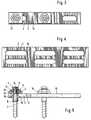
- FIG. 1 and 2show the arrangement laterally attached to a series of vertebral bodies, as may be required in ventral spinal surgery.
- the bone plateis curved in the transverse direction in order to better adapt to the contour of the vertebrae. In other applications, this may be unnecessary.
- Fig. 1it is assumed that the bone plate - as shown in Fig. 4 - has two rows of elongated holes to allow an offset screw arrangement in two rows of screws, while the bone plate shown in Figs. 2 and 3 contains only one row of elongated holes .
- the bone screws 1are held in the elongated holes 2 of the bone plates 3 by means of sleeves 4, the bore of which corresponds to the diameter of the shaft 5 of the bone screws with the required play.
- the bone screwsare each equipped with a collar 6 and a nut 7, which sits on a thread 8 arranged on the end of the shaft 5.
- the bone screwhas a hexagon socket 9 at the end.
- the sleevehas a counter flange 10 and a nut 11 on a thread 12.
- the nut 11is supported by a support plate 13 on the upper side of the bone plate 3, which has two cutting edges 14, which run transversely to the plane of the drawing in FIG. 5, on its underside.
- the top of the bone plateis serrated transversely to the direction of the elongated holes 2, as indicated at 15, the cutting edges 14 engaging in the grooves 15, whereby the support plate 13 is prevented from moving in the direction of the elongated holes 2 when the nut 11 is tightened .
- These edges or groovesform the roughness mentioned above.
- the counter flange 10is supported on the underside of the bone plate 3, wherein it lies within a groove 16 which accommodates it appropriately.
- the sleeve 4 and the counter flange 10, as can be seen better in FIG. 6,are laterally flattened, the flats 17 interacting with the flanks of the elongated holes 2 and the groove 16, respectively, in order to prevent the sleeve 4 from rotating when the nut 11 is tightened or released.
- the bone plate(with or without sleeves attached to it) can be used in the manner of a drilling jig.
- a guide instrumentcan be provided for the pre-drilling at an angle.
- sleeves 4 attached to the bone platecan also serve as guides for the further angular predrilling if the angular position of the bone fragment or vertebra relative to the plate is not to be changed.
- the hole in the vertebral bodyis then further drilled out via the shaft 5 of the screwed-in bone screw by means of a hollow milling cutter in order to receive the end of the sleeve 4 on the bone side.
- the sleevesare now connected to the bone plate. Then the bone plate with the sleeves is placed or put on the shanks of the screws inserted into the bone and the screws are secured with the nuts 7.
- the connection of the sleeves 4 to the bone platecan (but does not have to) be loose at this stage in order to enable a length correction (distraction, extraction) by means of the bone screws used. A special instrument can be provided for these purposes.
- the nuts 11are tightened. This ensures that the bone screws are secured at an angle, even if the bone is loosened.
- the screws 1are then possibly screwed further into the bone by attacking a tool on the nuts 7 or on the hexagon socket 9 until the bone plate 3 lies against the bone surface.
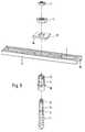
- the counter flange 10 'of the bone screw 1is formed in a convex-spherical manner on the side facing away from the bone, the center points of the spheres being at a large distance from one another. The same applies in the opposite direction to the mother 11 '.
- the counter flange 10 'acts together with a pressure plate 20, which is longitudinally displaceable in the groove 16' on the underside of the bone plate and carries two cutting edges 21 (analogous to the cutting edges 14 of the support plate 13), which are provided with transverse ribbing 22 at the base of the groove 16 'cooperate.
- the spherical surface of the nut 11 'acts together with a corresponding, concave-spherical surface of the support plate 13'.
- the underside of the support plate 13 'and the upper side 15' of the bone plateare roughened, as shown in FIG. 9, by corrugations running transversely to one another, so that a large number of discrete pyramid elevations are formed.
- the support plate 13 'can be offset not only in the longitudinal but also in the transverse direction with respect to the bone plate 3' and fixed by tightening the nut 11 ' will.
- the pressure plate 10 'in the groove 16'can only be moved in the longitudinal direction.
- the hole 2 'in the bone plate 3'is not only wider than the outer diameter of the sleeve 4 'in the longitudinal direction but also in the transverse direction.
- an angle adjustmentcan therefore also be carried out in a cross-sectional plane (FIG. 8).
Landscapes
- Health & Medical Sciences (AREA)
- Orthopedic Medicine & Surgery (AREA)
- Life Sciences & Earth Sciences (AREA)
- Surgery (AREA)
- Neurology (AREA)
- Heart & Thoracic Surgery (AREA)
- Engineering & Computer Science (AREA)
- Biomedical Technology (AREA)
- Nuclear Medicine, Radiotherapy & Molecular Imaging (AREA)
- Medical Informatics (AREA)
- Molecular Biology (AREA)
- Animal Behavior & Ethology (AREA)
- General Health & Medical Sciences (AREA)
- Public Health (AREA)
- Veterinary Medicine (AREA)
- Surgical Instruments (AREA)
- Prostheses (AREA)
Abstract
Translated fromGermanDescription
Translated fromGermanEs sind Knochenplattenanordnungen, insbesondere für die Wirbelsäulenchirurgie bekannt, die es gestatten, eine feste Winkelrelation zwischen der Knochenschraube und der Knochenplatte herzustellen, beispielsweise um einem Knochenfragment oder einem Wirbelkörper eine vorbestimmte Winkelstellung im Verhältnis zu benachbarten Fragmenten oder Wirbelkörpern zu geben (EP-PS 0 201 024, EP-OS 0 242 842). Dabei ist die Stelle, an der die Knochenschraube durch die Knochenplatte hindurchtritt, durch die Bohrungsanordnung in der Knochenplatte festgelegt. Die bekannten Anordnungen sind auch sehr dick. Ferner kann die Knochenplatte den Blick und den Zugang zu derjenigen Stelle behindern, an der eine Knochenschraube gesetzt werden soll. Schließlich haben manche bekannte Knochenplattenanordnungen den Nachteil, daß der Zusammenhalt zwischen Knochenplatte und Schraube sich löst, wenn die Schraube sich im Knochen lockert, wobei weiter die Gefahr besteht, daß die Schraube durch die Knochenplatte hindurch nach außen herauswandert. Das gilt auch für eine bekannte Anordnung (EP-A-0 410 309), bei der der halbsphärisch ausgebildete Kopf der Schraube in der sphärischen Vertiefung einer Stützplatte ruht, die ihrerseits an einer als Langloch ausgebildeten Durchgangsöffnung der Knochenplatte einstellbar ist und sich in der gewählten Stellung durch zusammenwirkende Riffelung hält.Bone plate assemblies, in particular for spinal surgery, are known which allow a fixed angular relationship to be established between the bone screw and the bone plate, for example in order to give a bone fragment or a vertebral body a predetermined angular position in relation to neighboring fragments or vertebral bodies (EP-PS 0 201 024, EP-OS 0 242 842). The location at which the bone screw passes through the bone plate is defined by the hole arrangement in the bone plate. The known arrangements are also very thick. Furthermore, the bone plate can obstruct the view and access to the point at which a bone screw is to be placed. Finally, some known bone plate assemblies have the disadvantage that the cohesion between the bone plate and the screw loosens when the screw loosens in the bone, with the further risk that the screw will move out through the bone plate. This also applies to a known arrangement (EP-A-0 410 309), in which the semi-spherical head of the screw rests in the spherical recess of a support plate, which in turn has an elongated hole on one trained through opening of the bone plate is adjustable and holds in the selected position by interacting corrugation.
Der Erfindung liegt daher die Aufgabe zugrunde, eine Knochenplattenanordnung der eingangs genannten Art zu schaffen, die größere Freiheit beim Setzen der Schraube und besseren Zugang zum Knochen ermöglicht und die auch dann winkelstabil bleibt, wenn die Schraube sich im Knochen lockert wobei das Auswandern dieser sich lockernden Schraube behindert wird.The invention is therefore based on the object to provide a bone plate arrangement of the type mentioned, which allows greater freedom when setting the screw and better access to the bone and which also remains stable when the screw loosens in the bone, the emigration of which loosens Screw is obstructed.
Die erfindungsgemäße Lösung besteht in den Merkmalen der Ansprüche.The solution according to the invention consists in the features of the claims.
Dadurch, daß die Hülse unabhängig vom Setzen der Knochenschraube an der Knochenplatte fixierbar ist, läßt sich die Winkellage der Knochenschraube gegenüber der Knochenplatte und/oder die Position der Knochenschraube entlang einem in der Knochenplatte vorgesehenen Langloch unabhängig vom Einbringen der Knochenschraube in den Knochen bestimmen.Because the sleeve can be fixed to the bone plate independently of the setting of the bone screw, the angular position of the bone screw relative to the bone plate and / or the position of the bone screw along an elongated hole provided in the bone plate can be determined independently of the insertion of the bone screw into the bone.
Zu diesem Zweck kann die Hülse so ausgebildet sein, daß sie eindeutig winkelfest mit der Platte verbunden werden kann, wobei die Winkelfestigkeit zwischen Knochenschrauben und Hülse dadurch gewährleistet ist, daß die Durchgangsöffnung in der Hülse beliebig lang und passend zum Durchmesser des Schraubenschafts ausgeführt werden kann. Besonders einfach und vorteilhaft ist eine Hülsenausführung, bei der am einen Ende ein Gewinde zur Aufnahme einer sich an der einen Seite der Knochenplatte abstützenden Mutter und nahe dem anderen Ende ein Gegenflansch zur Abstützung an der anderen Seite der Knochenplatte vorgesehen ist. Sobald feststeht, an welcher Stelle der Knochenplatte die Schraube mit dieser verbunden werden soll, kann die Hülse fest mit der Knochenplatte verschraubt werden. Nach dem Setzen der Schraube wird dann die Knochenplatte bzw. die daran vorgesehene Hülse auf die Schraube aufgesetzt.For this purpose, the sleeve can be designed so that it can be clearly connected at an angle to the plate, the angular strength between the bone screws and the sleeve being ensured in that the through opening in the sleeve can be of any length and suitable for the diameter of the screw shaft. A sleeve design is particularly simple and advantageous in which a thread is provided at one end for receiving a nut supported on one side of the bone plate and near the other end a counter flange is provided for support on the other side of the bone plate. As soon as it is clear at which point of the bone plate the screw is to be connected to it, the sleeve can be screwed firmly to the bone plate. After the screw has been set, the bone plate or the sleeve provided thereon is then placed on the screw.
Der Gegenflansch der Hülse ist zweckmäßigerweise so ausgebildet, daß er der Knochenplatte eine ebene Fläche zuwendet, durch die die Winkelstellung der Hülse gegenüber der Platte ausgebildet ist. Im allgemeinen ist Rechtwinkligkeit erwünscht, so daß der Gegenflansch rechtwinklig zur Hülse verläuft. Wenn eine schräge Anordnung der Schraube zur Knochenplatte beabsichtigt ist, kann stattdessen eine entsprechend winklige Anordnung des Gegenflanschs an der Hülse vorgesehen werden.The counter flange of the sleeve is expediently designed such that it faces the bone plate with a flat surface by which the angular position of the sleeve relative to the plate is formed. In general, perpendicularity is desirable so that the counter flange is perpendicular to the sleeve. If an oblique arrangement of the screw relative to the bone plate is intended, a corresponding angular arrangement of the counter flange on the sleeve can instead be provided.
Nach der Erfindung ist vorgesehen, daß das zur Aufnahme der Hülse vorgesehene Knochenplattenloch (bzw. Knochenplattenlöcher) mindestens in einer Richtung weiter als der äußere Hülsendurchmesser ist, so daß die Hülse in diesem Loch in mindestens einer Richtung verstellbar ist. Die positive Lokalisierung der Hülse gegenüber der Knochenplatte kann dann durch Klemmung an den Plattenoberflächen erfolgen. Diese wird erfindungsgemäß dadurch verbessert, daß wenigstens eine Seite der Knochenplatte und die damit zusammenwirkende Fläche einer mit der Hülse verbundenen Stützplatte oder des Gegenflansches der Hülse zueinander passend rauh ausgebildet sind. Wenn die Knochenplattenlöcher als Langlöcher ausgebildet sind, wird die Rauhigkeit zweckmäßigerweise als quer zur Langlochrichtung verlaufende Riefelung ausgeführt, um der Verschiebung in Langlochrichtung besseren Widerstand leisten zu können, während die Positionierung quer dazu durch das Langloch selbst erfolgen kann.According to the invention it is provided that the bone plate hole (or bone plate holes) provided for receiving the sleeve is at least in one direction wider than the outer sleeve diameter, so that the sleeve is adjustable in this hole in at least one direction. The sleeve can then be positively localized with respect to the bone plate by clamping on the plate surfaces. According to the invention, this is improved in that at least one side of the bone plate and the surface of a support plate connected to the sleeve or the counterflange of the sleeve, which cooperate therewith, are designed to be rough to match. If the bone plate holes are designed as elongated holes, the roughness is expediently designed as ribbing running transversely to the elongated hole direction, in order to be able to offer better resistance to the displacement in the elongated hole direction, while the positioning can take place transversely thereto through the elongated hole itself.
Wünscht man den Winkel der Knochenschraube gegenüber der Knochenplatte frei einstellen zu können, so kann nach der Erfindung vorgesehen sein, daß in der mutterseitigen und gegenflanschseitigen Abstützung der Hülse an der Knochenplatte je eine sphärische Stützfläche vorgesehen und wenigstens auf einer Seite die Stützkraft durch eine verschiebbare, über Rauhigkeit an der Knochenplatte anliegende Stützplatte übertragbar ist. Beispielsweise kann, wenn eine freie Positionierung der Knochenschraube in einer Flächenrichtung der Knochenplatte nicht erforderlich ist, das Durchgangsloch in der Knochenplatte mit einer sphärisch konvexen Fläche des Gegenflansches der Hülse zusammenwirken, während auf der anderen Seite die konvex-sphärische Unterfläche der Mutter mit einer Stützplatte zusammenwirkt, die ihrerseits ebenso wie die Knochenplattenoberseite mit einer Rauhigkeit versehen ist. Wenn hingegen eine Verschiebbarkeit der Schraube in einer Flächenrichtung der Knochenplatte erwünscht ist, wirkt die konvex-sphärische Fläche des Gegenflansches nicht unmittelbar mit der Knochenplatte zusammen, sondern mit einer Stützplatte, die ihrerseits mit der Unterseite der Knochenplatte über eine Rauhigkeit zusammenwirkt.If it is desired to be able to freely adjust the angle of the bone screw relative to the bone plate, it can be provided according to the invention that a spherical support surface is provided in the nut-side and counter-flange-side support of the sleeve on the bone plate and the support force at least on one side by a displaceable, can be transferred via roughness of the support plate lying against the bone plate. For example, if the bone screw is freely positioned in a surface direction of the Bone plate is not necessary, the through hole in the bone plate cooperate with a spherically convex surface of the counter flange of the sleeve, while on the other side the convex-spherical lower surface of the nut cooperates with a support plate, which in turn, like the upper side of the bone plate, is provided with a roughness. If, on the other hand, a displaceability of the screw in a surface direction of the bone plate is desired, the convex-spherical surface of the counter flange does not interact directly with the bone plate, but with a support plate, which in turn interacts with the underside of the bone plate via a roughness.
Nach einem weiteren Merkmal der Erfindung weist die Knochenschraube zur Verbindung mit der Hülse einen in der Hülsenbohrung aufzunehmenden Zapfen, zwischen dem Zapfen und dem Knochengewinde einen Bund und am bundfernen Ende des Zapfens ein Sicherungsglied auf, das von einem Gewinde am Ende des Bolzens und einer Mutter gebildet sein kann. Während herkömmliche, einen Kopf aufweisende Schrauben erst dann eingedreht werden können, wenn die Knochenplatte auf den Knochen aufgelegt ist, erlaubt diese Ausführung eine Vorgehensweise, bei welcher zunächst die Schraube(n) gesetzt wird (werden) und erst danach die Knochenplatte auf die Schraube(n) aufgesetzt wird. Die Platte behindert daher nicht die Zugänglichkeit zum Knochen, wenn die Schraube gesetzt wird. Die Anordnung bleibt auch in sich als feste Einheit erhalten, wenn eine Schraube sich im Knochen lockert. Insbesondere bleiben die Abstände und die Winkelstellungen von mit derselben Knochenplatte verbundenen Schrauben erhalten. Schließlich ist es auch nicht möglich, daß eine Schraube nach ihrer Lockerung im Knochen aus der Knochenplattenanordnung herauswandert.According to a further feature of the invention, the bone screw for connection to the sleeve has a pin to be received in the sleeve bore, a collar between the pin and the bone thread and a securing member at the end of the pin remote from the collar, which is provided by a thread at the end of the bolt and a nut can be formed. While conventional screws with a head can only be screwed in when the bone plate is placed on the bone, this embodiment allows a procedure in which the screw (s) is (are) first set and only then is the bone plate placed on the screw ( n) is put on. The plate therefore does not hinder access to the bone when the screw is placed. The arrangement remains in itself as a fixed unit if a screw loosens in the bone. In particular, the distances and the angular positions of screws connected to the same bone plate are retained. Finally, it is also not possible for a screw to move out of the bone plate arrangement after it has been loosened in the bone.
Nach einem weiteren Merkmal der Erfindung kann vorgesehen sein, daß die Schraube auch noch nach der Verbindung mit der Knochenplatte drehbar ist. Beim Setzen der Schraube kann nämlich u.U. noch nicht genau deren erforderliche Höhe im Verhältnis zur Knochenoberfläche abgeschätzt werden und sie wird daher bewußt weniger weit eingetrieben, als dies voraussichtlich erforderlich scheint. Erst nach der Verbindung der Mutter mit der Knochenplatte wird die Schraube so weit eingedreht, daß die Knochenplatte die gewünschte Lage an der Knochenoberfläche erhält. Dabei kann vorgesehen werden, daß die Knochenplatte nicht unter Druck an der Knochenoberfläche anliegt, wodurch erfindungsgemäß die Lockerungsgefahr weiter vermindert werden kann. Während nämlich bei bekannten Anordnungen die Knochenschraube ständig mit der Gegenkraft beaufschlagt ist, die den Druck der Knochenplatte auf die Knochenoberfläche ausgleicht, wodurch auch im Ruhezustand eine Knochenrückbildung im Bereich der Gewindegänge und damit eine Lockerung verursacht werden kann, ist die erfindungsgemäße Anordnung im Ruhezustand von derartigen Kräften frei.According to a further feature of the invention it can be provided that the screw can also be rotated after the connection to the bone plate. When setting the screw, it may not yet be possible to precisely determine the required height in the Relationship to the surface of the bone can be estimated and is therefore deliberately driven in less than expected. Only after the nut has been connected to the bone plate is the screw screwed in so far that the bone plate receives the desired position on the bone surface. It can be provided that the bone plate does not rest under pressure on the bone surface, whereby the risk of loosening can be further reduced according to the invention. While, in known arrangements, the bone screw is constantly subjected to the counterforce which balances the pressure of the bone plate on the bone surface, whereby bone regression in the area of the threads and thus loosening can also be caused in the idle state, the arrangement according to the invention is in the idle state of such Powers freely.
Die erwähnte Drehbarkeit der Knochenschraube nach ihrer Verbindung mit der Knochenplatte kann dann, wenn die Knochenschraube mittels einer Mutter an der Hülse gesichert wird, dadurch gewährleistet sein, daß das am Bolzenende zur Aufnahme der Mutter vorgesehene Gewinde so kurz bemessen ist, daß eine feste Auflage der Mutter an der Hülse nicht zustande kommt. Zum Drehen der Schraube kann man dann mit einem Werkzeug an der Mutter angreifen. Stattdessen könnte man natürlich auch Schlüsselflächen benutzen, die am Schraubenschaft vorgesehen sind. Jedoch sind derartige Maßnahmen im allgemeinen nicht notwendig, da normalerweise die Schraube auch dann noch jedenfalls in einschraubender Richtung mittels eines an der Mutter angreifenden Werkzeugs drehbar bleibt, wenn die Mutter in vollständige Anlage an der Knochenplatte oder eines mit ihr verbundenen Teils gelangt ist.The mentioned rotatability of the bone screw after its connection to the bone plate can then be ensured, if the bone screw is secured to the sleeve by means of a nut, that the thread provided on the bolt end for receiving the nut is dimensioned so short that a firm support of the Nut on the sleeve does not come about. To turn the screw, you can then grasp the nut with a tool. Instead, you could of course also use key surfaces that are provided on the screw shaft. However, such measures are generally not necessary, since the screw normally remains rotatable in the screwing-in direction by means of a tool that engages the nut when the nut comes into full contact with the bone plate or a part connected to it.
Die Knochenplatte kann, wie an sich bekannt, in Querrichtung gewölbt sein, um sich mit Knochenoberflächen entsprechender Wölbung stabiler verbinden zu können.The bone plate can, as is known per se, be arched in the transverse direction in order to be able to connect more stable to bone surfaces of corresponding curvature.
Die Erfindung wird im folgenden näher unter Bezugnahme auf die Zeichnung erläutert, die vorteilhafte Ausführungsbeispiele veranschaulicht. Darin zeigen:
- Fig. 1
- eine Vertikalansicht der an einem Wirbelkörper angebrachten Anordnung,
- Fig. 2
- eine Seitenansicht einer ähnlichen Anordnung,
- Fig. 3 und 4
- eine Knochenplatte mit einer bzw. zwei Reihen von Langlöchern,
- Fig. 5
- eine teilweise geschnittene Seitenansicht der Knochenplattenanordnung,
- Fig. 6
- eine Explosionsdarstellung der beteiligten Elemente,
- Fig. 7 und 8
- eine winkeleinstellbare Anordnung und
- Fig. 9
- eine Draufsicht.
- Fig. 1
- 4 shows a vertical view of the arrangement attached to a vertebral body,
- Fig. 2
- a side view of a similar arrangement,
- 3 and 4
- a bone plate with one or two rows of elongated holes,
- Fig. 5
- a partially sectioned side view of the bone plate arrangement,
- Fig. 6
- an exploded view of the elements involved,
- 7 and 8
- an angle adjustable arrangement and
- Fig. 9
- a top view.
Fig. 1 und 2 zeigen die Anordnung seitlich an eine Reihe von Wirbelkörpern angesetzt, wie es bei der ventralen Wirbelsäulenchirurgie erforderlich sein kann. Die Knochenplatte ist in Querrichtung gewölbt, um sich der Kontur der Wirbel besser anpassen zu können. In anderen Anwendungsfällen mag dies entbehrlich sein. In Fig. 1 ist vorausgesetzt, daß die Knochenplatte - wie in Fig. 4 dargestellt - zwei Reihen von Langlöchern aufweist, um eine versetzte Schraubenanordnung in zwei Schraubenreihen zu ermöglichen, während die in Fig. 2 und 3 dargestellte Knochenplatte lediglich eine Reihe von Langlöchern enthält.1 and 2 show the arrangement laterally attached to a series of vertebral bodies, as may be required in ventral spinal surgery. The bone plate is curved in the transverse direction in order to better adapt to the contour of the vertebrae. In other applications, this may be unnecessary. In Fig. 1 it is assumed that the bone plate - as shown in Fig. 4 - has two rows of elongated holes to allow an offset screw arrangement in two rows of screws, while the bone plate shown in Figs. 2 and 3 contains only one row of elongated holes .
Die Knochenschrauben 1 werden in den Langlöchern 2 der Knochenplatten 3 mittels Hülsen 4 gehalten, deren Bohrung mit dem erforderlichen Spiel dem Durchmesser des Schafts 5 der Knochenschrauben entspricht. Zur Befestigung in den Hülsen sind die Knochenschrauben je mit einem Bund 6 und einer Mutter 7 ausgerüstet, die auf einem auf dem Ende des Schafts 5 angeordneten Gewinde 8 sitzt. Die Knochenschraube besitzt, um unabhängig gedreht werden zu können, am Ende einen Innensechskant 9.The bone screws 1 are held in the
Die Hülse weist zur Verbindung mit der Knochenplatte 3 einen Gegenflansch 10 sowie eine Mutter 11 auf einem Gewinde 12 auf. Die Mutter 11 stützt sich über eine Stützplatte 13 an der Oberseite der Knochenplatte 3 ab, die zwei quer zur Zeichenebene der Fig. 5 verlaufende, schneidenförmige Erhöhungen 14 an ihrer Unterseite hat. Die Oberseite der Knochenplatte ist quer zur Richtung der Langlöcher 2 gerieft, wie bei 15 angedeutet ist, wobei die Schneiden 14 in die Riefen 15 eingreifen, wodurch die Stützplatte 13 an einer Verschiebung in Richtung der Langlöcher 2 gehindert ist, wenn die Mutter 11 angezogen ist. Diese Schneiden bzw. Riefen bilden die weiter oben erwähnte Rauhigkeit. Dabei stützt sich der Gegenflansch 10 an der Unterseite der Knochenplatte 3 ab, wobei er innerhalb einer Nut 16 liegt, die ihn passend aufnimmt. Die Hülse 4 und der Gegenflansch 10 sind, wie besser in Fig. 6 erkennbar ist, seitlich abgeflacht, wobei die Abflachungen 17 mit den Flanken der Langlöcher 2 bzw. der Nut 16 zusammenwirken, um die Hülse 4 an Drehung zu hindern, wenn die Mutter 11 angezogen oder gelöst wird.For connection to the
Für das Vorgehen bei der Operation ist kennzeichnend, daß zunächst die Schrauben gesetzt werden, wobei die Knochenplatte (mit oder ohne daran befestigte Hülsen) in der Art einer Bohrlehre benutzt werden kann. Für das winkelgerechte Vorbohren kann ein Führungsinstrument vorgesehen sein. Statt dessen können an den vorgesehenen Stellen auch an der Knochenplatte angebrachte Hülsen 4 als Führung für das weitere winkelgerechte Vorbohren dienen, wenn die Winkelstellung des Knochenfragments oder Wirbels gegenüber der Platte nicht verändert werden soll.It is characteristic of the procedure during the operation that the screws are first set, whereby the bone plate (with or without sleeves attached to it) can be used in the manner of a drilling jig. A guide instrument can be provided for the pre-drilling at an angle. Instead,
Anschließend wird über den Schaft 5 der eingeschraubten Knochenschraube das Loch im Wirbelkörper mittels eines Hohlfräsers weiter aufgebohrt zur Aufnahme des knochenseitigen Endes der Hülse 4. Gleichzeitig kann der Tiefensitz der Knochenschraube im Wirbelkörper kontrolliert werden.The hole in the vertebral body is then further drilled out via the
Wenn dies noch nicht geschehen ist, werden nun die Hülsen mit der Knochenplatte verbunden. Danach wird die Knochenplatte mit den Hülsen auf die Schäfte der in den Knochen eingesetzten Schrauben gesetzt bzw. gesteckt und werden die Schrauben mit den Muttern 7 gesichert. Die Verbindung der Hülsen 4 mit der Knochenplatte kann (aber muß nicht) in diesem Stadium noch lose sein, um eine Längenkorrektur (Distraktion, Extraktion) mittels der eingesetzten Knochenschrauben zu ermöglichen. Ein besonderes Instrument kann für diese Zwecke vorgesehen sein. Danach werden die Muttern 11 fest angezogen. Damit ist eine winkelstabile Absicherung der Knochenschrauben, auch bei eventueller Lockerung im Knochen, erreicht. Abschließend werden dann die Schrauben 1 durch Angriff eines Werkzeugs an den Muttern 7 oder an dem Innensechskant 9 so ggfs. weiter in den Knochen eingeschraubt, bis die Knochenplatte 3 an der Knochenoberfläche anliegt.If this has not yet been done, the sleeves are now connected to the bone plate. Then the bone plate with the sleeves is placed or put on the shanks of the screws inserted into the bone and the screws are secured with the nuts 7. The connection of the
Die Fig. 7 und 8 zeigen einen Längs- und Querschnitt durch eine ähnliche Anordnung, die auch eine Schrägstellung der Schrauben zur Knochenplatte gestattet. Der Gegenflansch 10' der Knochenschraube 1 ist auf der dem Knochen abgewandten Seite konvex-sphärisch ausgebildet, wobei die Sphärenmittelpunkte großen Abstand voneinander haben. Dasselbe gilt gegensinnig für die Mutter 11'. Der Gegenflansch 10' wirkt zusammen mit einer Druckplatte 20, die in der Nut 16' auf der Unterseite der Knochenplatte in Längsrichtung verschiebbar ist und zwei Schneiden 21 (analog den Schneiden 14 der Stützplatte 13) trägt, die mit einer Querriefelung 22 am Grunde der Nut 16' zusammenwirken. Die sphärische Fläche der Mutter 11' wirkt zusammen mit einer entsprechenden, konkav-sphärischen Fläche der Stützplatte 13'. Die Unterseite der Stützplatte 13' und die Oberseite 15' der Knochenplatte sind aufgerauht, und zwar - wie Fig. 9 zeigt - durch quer zueinander verlaufende Riefelungen, so daß sich eine Vielzahl diskreter Pyramidenerhöhungen bildet. Dadurch kann die Stützplatte 13' nicht nur in Längs-, sondern auch in Querrichtung gegenüber der Knochenplatte 3' versetzt und durch Anziehen der Mutter 11' fixiert werden. Demgegenüber kann die Druckplatte 10' in der Nut 16' lediglich in Längsrichtung verschoben werden. Das Loch 2' in der Knochenplatte 3' ist nicht nur in Längsrichtung, sondern auch in Querrichtung weiter als der Außendurchmesser der Hülse 4' ausgeführt. Zusätzlich zu dem Versatz und der Abwinkelung der Schraube in einer Längsschnittebene (Fig. 7) kann daher auch in einer Querschnittsebene (Fig. 8) eine Winkelverstellung vorgenommen werden.7 and 8 show a longitudinal and cross section through a similar arrangement, which also allows the screws to be inclined to the bone plate. The counter flange 10 'of the
Die Handhabung stimmt mit der oben erläuterten im wesentlichen überein.The handling is essentially the same as that explained above.
Claims (10)
Translated fromGermanApplications Claiming Priority (2)
| Application Number | Priority Date | Filing Date | Title |
|---|---|---|---|
| DE9104025UDE9104025U1 (en) | 1991-04-03 | 1991-04-03 | Bone plate arrangement |
| DE9104025U | 1991-04-03 |
Publications (2)
| Publication Number | Publication Date |
|---|---|
| EP0507162A1true EP0507162A1 (en) | 1992-10-07 |
| EP0507162B1 EP0507162B1 (en) | 1994-03-09 |
Family
ID=6865927
Family Applications (1)
| Application Number | Title | Priority Date | Filing Date |
|---|---|---|---|
| EP92104908AExpired - LifetimeEP0507162B1 (en) | 1991-04-03 | 1992-03-20 | Bone plate device |
Country Status (5)
| Country | Link |
|---|---|
| US (1) | US5234431A (en) |
| EP (1) | EP0507162B1 (en) |
| JP (1) | JP2977662B2 (en) |
| DE (2) | DE9104025U1 (en) |
| ES (1) | ES2051136T3 (en) |
Cited By (17)
| Publication number | Priority date | Publication date | Assignee | Title |
|---|---|---|---|---|
| EP0600290A1 (en)* | 1992-12-04 | 1994-06-08 | Waldemar Link (GmbH & Co.) | Apparatus to unite bone fragments by means of a bone plate |
| WO1994016634A1 (en)* | 1993-01-25 | 1994-08-04 | Synthes Ag | Strain washer for plate osteosynthesis |
| FR2704137A1 (en)* | 1993-04-20 | 1994-10-28 | Biotecnic Sa | Spinal osteosynthesis device |
| FR2718943A1 (en)* | 1994-04-21 | 1995-10-27 | Jbs Sa | Reinforced bar with three branches for osteosynthesis of the spine. |
| WO1997001991A1 (en)* | 1995-07-03 | 1997-01-23 | Synthes Ag Chur | Bone fragment-fixing device |
| AU678196B2 (en)* | 1992-10-23 | 1997-05-22 | Smith & Nephew Richards Inc. | Internal fixators |
| US5681310A (en)* | 1994-07-20 | 1997-10-28 | Yuan; Hansen A. | Vertebral auxiliary fixation device having holding capability |
| US5810823A (en)* | 1994-09-12 | 1998-09-22 | Synthes (U.S.A.) | Osteosynthetic bone plate and lock washer |
| FR2790941A1 (en)* | 1999-03-16 | 2000-09-22 | Materiel Orthopedique En Abreg | INSTRUMENTATION OF RACHIDIAN OSTEOSYNTHESIS WITH PLATE AND PEDICULAR SCREW OR TRANSVERSE CONNECTOR BETWEEN A VERTEBRAL ROD AND A PEDICULAR SCREW |
| WO2001003591A1 (en)* | 1999-07-07 | 2001-01-18 | Synthes Ag Chur | Angle-adjustable bone screw and device for the osteosynthetic bone fixation |
| WO2001003593A1 (en)* | 1999-07-07 | 2001-01-18 | Synthes Ag Chur | Bone screw with axially two-part screw head |
| US6827743B2 (en) | 2001-02-28 | 2004-12-07 | Sdgi Holdings, Inc. | Woven orthopedic implants |
| US7041138B2 (en) | 2001-02-28 | 2006-05-09 | Sdgi Holdings, Inc. | Flexible spine stabilization systems |
| US7229441B2 (en) | 2001-02-28 | 2007-06-12 | Warsaw Orthopedic, Inc. | Flexible systems for spinal stabilization and fixation |
| US7344539B2 (en) | 2001-03-30 | 2008-03-18 | Depuy Acromed, Inc. | Intervertebral connection system |
| WO2009043827A1 (en)* | 2007-09-26 | 2009-04-09 | Zimmer Gmbh | Bone anchoring device for the operative repair of fractures |
| EP2198796A1 (en) | 2008-12-19 | 2010-06-23 | Sepitec Foundation | Bone screw |
Families Citing this family (219)
| Publication number | Priority date | Publication date | Assignee | Title |
|---|---|---|---|---|
| US5545228A (en)* | 1991-08-15 | 1996-08-13 | Smith & Nephew Richards Inc. | Offset bone bolt |
| US5480440A (en)* | 1991-08-15 | 1996-01-02 | Smith & Nephew Richards, Inc. | Open surgical technique for vertebral fixation with subcutaneous fixators positioned between the skin and the lumbar fascia of a patient |
| US5603713A (en)* | 1991-09-24 | 1997-02-18 | Aust; Gilbert M. | Anterior lumbar/cervical bicortical compression plate |
| US5397363A (en)* | 1992-08-11 | 1995-03-14 | Gelbard; Steven D. | Spinal stabilization implant system |
| US5382248A (en)* | 1992-09-10 | 1995-01-17 | H. D. Medical, Inc. | System and method for stabilizing bone segments |
| DE69320593T2 (en)* | 1992-11-25 | 1999-03-04 | Codman & Shurtleff, Inc., Randolph, Mass. | Bone plate system |
| US5545164A (en)* | 1992-12-28 | 1996-08-13 | Advanced Spine Fixation Systems, Incorporated | Occipital clamp assembly for cervical spine rod fixation |
| US5531745A (en)* | 1993-03-11 | 1996-07-02 | Danek Medical, Inc. | System for stabilizing the spine and reducing spondylolisthesis |
| WO1994026194A1 (en)* | 1993-05-18 | 1994-11-24 | Schäfer Micomed GmbH | Holding device for use in bone surgery |
| US5344421A (en)* | 1993-07-16 | 1994-09-06 | Amei Technologies Inc. | Apparatus and method for adjusting a bone plate |
| FR2709410B1 (en)* | 1993-09-02 | 1995-11-03 | Jbs Sa | Clip plate for osteosynthesis. |
| USD368777S (en) | 1993-09-15 | 1996-04-09 | Zimmer, Inc. | Orthopaedic washer |
| WO1995010238A1 (en)* | 1993-10-08 | 1995-04-20 | Chaim Rogozinski | Spinal treatment apparatus and method including multi-directional attachment member |
| US5611800A (en)* | 1994-02-15 | 1997-03-18 | Alphatec Manufacturing, Inc. | Spinal fixation system |
| GB2288122B (en)* | 1994-04-07 | 1997-11-26 | Univ Brunel | Connection device |
| AU3207895A (en)* | 1994-08-23 | 1996-03-14 | Spine-Tech, Inc. | Cervical spine stabilization system |
| US5674296A (en)* | 1994-11-14 | 1997-10-07 | Spinal Dynamics Corporation | Human spinal disc prosthesis |
| US5976141A (en)* | 1995-02-23 | 1999-11-02 | Synthes (U.S.A.) | Threaded insert for bone plate screw hole |
| US5728127A (en)* | 1995-06-27 | 1998-03-17 | Acro Med Corporation | Apparatus for maintaining vertebrae of a spinal column in a desired spatial relationship |
| CA2158890C (en)* | 1995-09-22 | 2002-01-22 | John Runciman | Spherical washer for use with a bone screw |
| USD374287S (en) | 1995-12-12 | 1996-10-01 | Zimmer, Inc. | Orthopadeic washer |
| USD374482S (en) | 1995-12-12 | 1996-10-08 | Zimmer, Inc. | Orthopaedic washer |
| USD375791S (en) | 1995-12-12 | 1996-11-19 | Zimmer, Inc. | Orthopaedic washer |
| USD374286S (en) | 1995-12-12 | 1996-10-01 | Zimmer, Inc. | Orthopaedic washer |
| US5879391A (en)* | 1996-09-30 | 1999-03-09 | Johnson & Johnson Professional, Inc. | Modular prosthesis |
| US6004323A (en)* | 1997-02-04 | 1999-12-21 | The University Of Iowa Research Foundation | Surgically implantable fastening system |
| ES2297092T3 (en)* | 1997-02-11 | 2008-05-01 | Warsaw Orthopedic, Inc. | PREVIOUS CERVICAL PLATE OF UNIQUE BLOCK. |
| US6139550A (en) | 1997-02-11 | 2000-10-31 | Michelson; Gary K. | Skeletal plating system |
| WO1998041160A1 (en)* | 1997-03-17 | 1998-09-24 | Intellect Medical Limited | Cervical fixation system |
| US6017345A (en)* | 1997-05-09 | 2000-01-25 | Spinal Innovations, L.L.C. | Spinal fixation plate |
| FR2763828B1 (en)* | 1997-05-29 | 1999-07-23 | Aesculap Jbs | VERTEBRAL OSTEOSYNTHESIS PLATE SYSTEM |
| WO2000004851A1 (en) | 1998-07-22 | 2000-02-03 | Spinal Dynamics Corporation | Threaded cylindrical multidiscoid single or multiple array disc prosthesis |
| US6749635B1 (en) | 1998-09-04 | 2004-06-15 | Sdgi Holdings, Inc. | Peanut spectacle multi discoid thoraco-lumbar disc prosthesis |
| WO2000013619A1 (en)* | 1998-09-04 | 2000-03-16 | Spinal Dynamics Corporation | Peanut spectacle multi discoid thoraco-lumbar disc prosthesis |
| US5984924A (en)* | 1998-10-07 | 1999-11-16 | Isola Implants, Inc. | Bone alignment system having variable orientation bone anchors |
| US6302883B1 (en)* | 1998-10-22 | 2001-10-16 | Depuy Acromed, Inc. | Bone plate-ratcheting compression apparatus |
| US6183478B1 (en) | 1999-02-04 | 2001-02-06 | Depuy Orthopaedics, Inc. | Temporary fixation device |
| US6315779B1 (en) | 1999-04-16 | 2001-11-13 | Sdgi Holdings, Inc. | Multi-axial bone anchor system |
| US6280445B1 (en) | 1999-04-16 | 2001-08-28 | Sdgi Holdings, Inc. | Multi-axial bone anchor system |
| US7018380B2 (en)* | 1999-06-10 | 2006-03-28 | Cole J Dean | Femoral intramedullary rod system |
| AU7118100A (en)* | 1999-09-03 | 2001-04-10 | Daniel J. Cook | Temporary spine fixation device and method |
| US6692503B2 (en)* | 1999-10-13 | 2004-02-17 | Sdgi Holdings, Inc | System and method for securing a plate to the spinal column |
| US6312431B1 (en) | 2000-04-24 | 2001-11-06 | Wilson T. Asfora | Vertebrae linking system |
| JP2004516044A (en) | 2000-08-08 | 2004-06-03 | エスディージーアイ・ホールディングス・インコーポレーテッド | Method and apparatus for improving stereotactic body transplantation |
| US7125380B2 (en)* | 2000-08-08 | 2006-10-24 | Warsaw Orthopedic, Inc. | Clamping apparatus and methods |
| CA2429246C (en) | 2000-08-08 | 2011-06-07 | Vincent Bryan | Implantable joint prosthesis |
| US7601174B2 (en)* | 2000-08-08 | 2009-10-13 | Warsaw Orthopedic, Inc. | Wear-resistant endoprosthetic devices |
| US6413259B1 (en) | 2000-12-14 | 2002-07-02 | Blackstone Medical, Inc | Bone plate assembly including a screw retaining member |
| US6562045B2 (en) | 2001-02-13 | 2003-05-13 | Sdgi Holdings, Inc. | Machining apparatus |
| US7686807B2 (en)* | 2001-03-22 | 2010-03-30 | Interventional Spine, Inc. | Tool for bone fixation device |
| US6641583B2 (en) | 2001-03-29 | 2003-11-04 | Endius Incorporated | Apparatus for retaining bone portions in a desired spatial relationship |
| US6511481B2 (en) | 2001-03-30 | 2003-01-28 | Triage Medical, Inc. | Method and apparatus for fixation of proximal femoral fractures |
| US6887243B2 (en) | 2001-03-30 | 2005-05-03 | Triage Medical, Inc. | Method and apparatus for bone fixation with secondary compression |
| FR2823095B1 (en) | 2001-04-06 | 2004-02-06 | Ldr Medical | RACHIS OSTEOSYNTHESIS DEVICE AND PLACEMENT METHOD |
| US20050240187A1 (en) | 2004-04-22 | 2005-10-27 | Huebner Randall J | Expanded fixation of bones |
| US7537604B2 (en)* | 2002-11-19 | 2009-05-26 | Acumed Llc | Bone plates with slots |
| US7326212B2 (en) | 2002-11-19 | 2008-02-05 | Acumed Llc | Bone plates with reference marks |
| US7717945B2 (en) | 2002-07-22 | 2010-05-18 | Acumed Llc | Orthopedic systems |
| US6770075B2 (en) | 2001-05-17 | 2004-08-03 | Robert S. Howland | Spinal fixation apparatus with enhanced axial support and methods for use |
| US7314467B2 (en) | 2002-04-24 | 2008-01-01 | Medical Device Advisory Development Group, Llc. | Multi selective axis spinal fixation system |
| US7097645B2 (en)* | 2001-06-04 | 2006-08-29 | Sdgi Holdings, Inc. | Dynamic single-lock anterior cervical plate system having non-detachably fastened and moveable segments |
| CA2443429C (en) | 2001-06-04 | 2010-08-10 | Gary Karlin Michelson | Anterior cervical plate system having vertebral body engaging anchors, connecting plate, and method for installation thereof |
| US7186256B2 (en)* | 2001-06-04 | 2007-03-06 | Warsaw Orthopedic, Inc. | Dynamic, modular, single-lock anterior cervical plate system having assembleable and movable segments |
| JP4283665B2 (en)* | 2001-06-04 | 2009-06-24 | ウォーソー・オーソペディック・インコーポレーテッド | Dynamic plate for anterior cervical spine with movable segments |
| US7044952B2 (en)* | 2001-06-06 | 2006-05-16 | Sdgi Holdings, Inc. | Dynamic multilock anterior cervical plate system having non-detachably fastened and moveable segments |
| US7041105B2 (en)* | 2001-06-06 | 2006-05-09 | Sdgi Holdings, Inc. | Dynamic, modular, multilock anterior cervical plate system having detachably fastened assembleable and moveable segments |
| FR2831049B1 (en)* | 2001-10-18 | 2004-08-13 | Ldr Medical | PLATE FOR OSTEOSYNTHESIS DEVICE AND PRE-ASSEMBLY METHOD |
| US6783527B2 (en) | 2001-10-30 | 2004-08-31 | Sdgi Holdings, Inc. | Flexible spinal stabilization system and method |
| FR2832308B1 (en)* | 2001-11-22 | 2004-09-24 | Guillaume Derouet | ORTHOPEDIC IMPLANT CONSTITUTES A SUPPORT STRUCTURE EQUIPPED WITH AT LEAST ONE ORIFICE FOR THE PASSING OF A FIXATION SCREW ASSOCIATED WITH A NUT |
| US6755833B1 (en)* | 2001-12-14 | 2004-06-29 | Kamaljit S. Paul | Bone support assembly |
| US7070599B2 (en)* | 2002-07-24 | 2006-07-04 | Paul Kamaljit S | Bone support assembly |
| US6723098B1 (en) | 2002-03-12 | 2004-04-20 | Mrugesh K. Shah | Bone fixation plate having clip members |
| US20030187443A1 (en)* | 2002-03-27 | 2003-10-02 | Carl Lauryssen | Anterior bone plate system and method of use |
| US6793678B2 (en) | 2002-06-27 | 2004-09-21 | Depuy Acromed, Inc. | Prosthetic intervertebral motion disc having dampening |
| US7001389B1 (en) | 2002-07-05 | 2006-02-21 | Navarro Richard R | Fixed and variable locking fixation assembly |
| FR2842093B1 (en)* | 2002-07-12 | 2005-04-15 | Scient X | BONE ANCHORING DEVICE WITH SPHERICAL JOINT |
| JP4988203B2 (en) | 2002-07-19 | 2012-08-01 | インターヴェンショナル スパイン、インコーポレイテッド | Spinal fixation method and spinal fixation device |
| CN1309352C (en) | 2002-07-22 | 2007-04-11 | 精密医疗责任有限公司 | Bone fusion system |
| US7066938B2 (en) | 2002-09-09 | 2006-06-27 | Depuy Spine, Inc. | Snap-on spinal rod connector |
| US8002812B2 (en)* | 2002-10-10 | 2011-08-23 | Us Spine, Inc. | Bone fixation implant system and method |
| US7563275B2 (en)* | 2002-10-10 | 2009-07-21 | U.S. Spinal Technologies, Llc | Bone fixation implant system and method |
| CA2504215A1 (en)* | 2002-10-28 | 2004-05-13 | Blackstone Medical, Inc. | Bone plate assembly provided with screw locking mechanisms |
| US7682392B2 (en) | 2002-10-30 | 2010-03-23 | Depuy Spine, Inc. | Regenerative implants for stabilizing the spine and devices for attachment of said implants |
| US20040087952A1 (en)* | 2002-10-31 | 2004-05-06 | Amie Borgstrom | Universal polyaxial washer assemblies |
| AU2003294414B2 (en)* | 2002-11-19 | 2009-03-12 | Acumed Llc | Deformable bone plates |
| AU2003294342A1 (en) | 2002-11-19 | 2004-06-15 | Acumed Llc | Guide system for bone-repair devices |
| US7094238B2 (en) | 2002-11-22 | 2006-08-22 | Sdgi Holdings, Inc. | Variable angle adaptive plate |
| US8172885B2 (en) | 2003-02-05 | 2012-05-08 | Pioneer Surgical Technology, Inc. | Bone plate system |
| US20040158254A1 (en)* | 2003-02-12 | 2004-08-12 | Sdgi Holdings, Inc. | Instrument and method for milling a path into bone |
| JP2006519088A (en)* | 2003-02-28 | 2006-08-24 | トリアージ メディカル、 インコーポレイテッド | Distal bone anchor attachment tool with secondary compression |
| US7608096B2 (en)* | 2003-03-10 | 2009-10-27 | Warsaw Orthopedic, Inc. | Posterior pedicle screw and plate system and methods |
| DE602004001398T2 (en)* | 2003-03-20 | 2007-06-14 | Stryker Trauma S.A. | BONE CONNECTION DEVICE |
| WO2004098453A2 (en)* | 2003-05-06 | 2004-11-18 | Triage Medical, Inc. | Proximal anchors for bone fixation system |
| US7309340B2 (en) | 2003-06-20 | 2007-12-18 | Medicinelodge, Inc. | Method and apparatus for bone plating |
| WO2004112587A2 (en) | 2003-06-20 | 2004-12-29 | Acumed Llc | Bone plates with intraoperatively tapped apertures |
| US6945975B2 (en)* | 2003-07-07 | 2005-09-20 | Aesculap, Inc. | Bone fixation assembly and method of securement |
| US6945974B2 (en)* | 2003-07-07 | 2005-09-20 | Aesculap Inc. | Spinal stabilization implant and method of application |
| US7635365B2 (en) | 2003-08-28 | 2009-12-22 | Ellis Thomas J | Bone plates |
| US20050049595A1 (en) | 2003-09-03 | 2005-03-03 | Suh Sean S. | Track-plate carriage system |
| US7909860B2 (en) | 2003-09-03 | 2011-03-22 | Synthes Usa, Llc | Bone plate with captive clips |
| US7833251B1 (en)* | 2004-01-06 | 2010-11-16 | Nuvasive, Inc. | System and method for performing spinal fixation |
| US20050177160A1 (en)* | 2004-02-10 | 2005-08-11 | Baynham Bret O. | Dynamic cervical plate |
| US8002809B2 (en)* | 2004-02-10 | 2011-08-23 | Atlas Spine, Inc. | Dynamic cervical plate |
| US8328854B2 (en)* | 2004-02-10 | 2012-12-11 | Atlas Spine, Inc. | Cervical plate ratchet pedicle screws |
| US7815666B2 (en)* | 2004-02-10 | 2010-10-19 | Atlas Spine, Inc. | Dynamic cervical plate |
| US7740649B2 (en) | 2004-02-26 | 2010-06-22 | Pioneer Surgical Technology, Inc. | Bone plate system and methods |
| US8900277B2 (en) | 2004-02-26 | 2014-12-02 | Pioneer Surgical Technology, Inc. | Bone plate system |
| US7491221B2 (en)* | 2004-03-23 | 2009-02-17 | Stryker Spine | Modular polyaxial bone screw and plate |
| US7645294B2 (en) | 2004-03-31 | 2010-01-12 | Depuy Spine, Inc. | Head-to-head connector spinal fixation system |
| US7717939B2 (en) | 2004-03-31 | 2010-05-18 | Depuy Spine, Inc. | Rod attachment for head to head cross connector |
| US7789899B2 (en)* | 2004-12-30 | 2010-09-07 | Warsaw Orthopedic, Inc. | Bone anchorage screw with built-in hinged plate |
| US7524323B2 (en)* | 2004-04-16 | 2009-04-28 | Kyphon Sarl | Subcutaneous support |
| US7811311B2 (en)* | 2004-12-30 | 2010-10-12 | Warsaw Orthopedic, Inc. | Screw with deployable interlaced dual rods |
| US7618418B2 (en)* | 2004-04-16 | 2009-11-17 | Kyphon Sarl | Plate system for minimally invasive support of the spine |
| US7648520B2 (en)* | 2004-04-16 | 2010-01-19 | Kyphon Sarl | Pedicle screw assembly |
| WO2005102193A2 (en) | 2004-04-19 | 2005-11-03 | Acumed, Llc | Placement of fasteners into bone |
| US7717938B2 (en) | 2004-08-27 | 2010-05-18 | Depuy Spine, Inc. | Dual rod cross connectors and inserter tools |
| US7722654B2 (en)* | 2004-10-05 | 2010-05-25 | Warsaw Orthopedic, Inc. | Spinal implants with multi-axial anchor assembly and methods |
| US7794477B2 (en)* | 2004-10-05 | 2010-09-14 | Warsaw Orthopedic, Inc. | Spinal implants and methods with extended multi-axial anchor assemblies |
| US7572280B2 (en)* | 2004-10-05 | 2009-08-11 | Warsaw Orthopedic, Inc. | Multi-axial anchor assemblies for spinal implants and methods |
| US9615866B1 (en) | 2004-10-18 | 2017-04-11 | Nuvasive, Inc. | Surgical fixation system and related methods |
| MX2007005081A (en)* | 2004-10-26 | 2007-10-03 | U S Spinal Technologies Llc | Bone fixation implant system and method. |
| WO2006058221A2 (en) | 2004-11-24 | 2006-06-01 | Abdou Samy M | Devices and methods for inter-vertebral orthopedic device placement |
| US7635364B2 (en)* | 2004-12-01 | 2009-12-22 | Synthes Usa, Llc | Unidirectional translation system for bone fixation |
| US7736380B2 (en) | 2004-12-21 | 2010-06-15 | Rhausler, Inc. | Cervical plate system |
| US7998217B1 (en) | 2005-02-02 | 2011-08-16 | Biomet Manufacturing Corp. | Modular offset stem implants |
| US8016887B1 (en)* | 2005-03-24 | 2011-09-13 | Cardinal Spine, Llc | Spinal implant with overlay |
| US7794481B2 (en) | 2005-04-22 | 2010-09-14 | Warsaw Orthopedic, Inc. | Force limiting coupling assemblies for spinal implants |
| US7695499B2 (en)* | 2005-04-29 | 2010-04-13 | Warsaw Orthopedic, Inc. | System, devices and method for augmenting existing fusion constructs |
| US7727239B2 (en)* | 2005-06-10 | 2010-06-01 | Zimmer Technology, Inc. | Milling system with guide paths and related methods for resecting a joint articulation surface |
| US7883531B2 (en)* | 2005-07-06 | 2011-02-08 | Stryker Spine | Multi-axial bone plate system |
| US7625394B2 (en)* | 2005-08-05 | 2009-12-01 | Warsaw Orthopedic, Inc. | Coupling assemblies for spinal implants |
| US20130296939A1 (en)* | 2005-11-22 | 2013-11-07 | Richard Perkins | Adjustable spinous process spacer device and method of treating spinal disorders |
| US9907580B2 (en)* | 2005-11-22 | 2018-03-06 | Bryson Medical Technology Llc | Adjustable spinous process spacer device and method of treating spinal disorders |
| EP1968466A2 (en) | 2005-12-19 | 2008-09-17 | M. S. Abdou | Devices for inter-vertebral orthopedic device placement |
| KR20090015073A (en)* | 2006-04-21 | 2009-02-11 | 인터벤셔널 스파인, 인코포레이티드 | Methods and instruments for spinal fixation |
| US20070270820A1 (en)* | 2006-04-26 | 2007-11-22 | Sdgi Holdings, Inc. | Revision fixation plate and method of use |
| US7842093B2 (en)* | 2006-07-18 | 2010-11-30 | Biomet Manufacturing Corp. | Method and apparatus for a knee implant |
| US8066750B2 (en) | 2006-10-06 | 2011-11-29 | Warsaw Orthopedic, Inc | Port structures for non-rigid bone plates |
| US8206390B2 (en)* | 2006-11-02 | 2012-06-26 | Warsaw Orthopedic, Inc. | Uni-directional ratcheting bone plate assembly |
| US8361117B2 (en) | 2006-11-08 | 2013-01-29 | Depuy Spine, Inc. | Spinal cross connectors |
| WO2008070863A2 (en) | 2006-12-07 | 2008-06-12 | Interventional Spine, Inc. | Intervertebral implant |
| US20080255619A1 (en)* | 2007-04-10 | 2008-10-16 | Schneiderman Gary A | Posterior spinal fixation with colinear facet screw |
| US8353937B2 (en)* | 2007-05-22 | 2013-01-15 | Warsaw Orthopedic, Inc. | Spinal stabilization systems and methods |
| US8133283B2 (en)* | 2007-06-06 | 2012-03-13 | Kenneth Mitchell Wilson | Scapho-lunate fixation implants and methods of use |
| US7998176B2 (en) | 2007-06-08 | 2011-08-16 | Interventional Spine, Inc. | Method and apparatus for spinal stabilization |
| US20080312698A1 (en)* | 2007-06-14 | 2008-12-18 | Bergeron Brian J | Device and system for stabilizing movement between bony tissue and method for implanting |
| US8900307B2 (en) | 2007-06-26 | 2014-12-02 | DePuy Synthes Products, LLC | Highly lordosed fusion cage |
| US8623019B2 (en) | 2007-07-03 | 2014-01-07 | Pioneer Surgical Technology, Inc. | Bone plate system |
| US8361126B2 (en) | 2007-07-03 | 2013-01-29 | Pioneer Surgical Technology, Inc. | Bone plate system |
| DE102007034169A1 (en)* | 2007-07-23 | 2009-01-29 | Karl Leibinger Medizintechnik Gmbh & Co. Kg | Medical synthesis system and method for connecting a multi-part medical synthesis system |
| US20090105755A1 (en)* | 2007-10-22 | 2009-04-23 | Warsaw Orthopedics, Inc. | Apparatus and method for connecting spinal fixation systems together |
| EP2237748B1 (en) | 2008-01-17 | 2012-09-05 | Synthes GmbH | An expandable intervertebral implant |
| US20090216273A1 (en)* | 2008-02-19 | 2009-08-27 | U. S. Spinal Technologies, L.L.C. | Curved facet joint fixation assembly and associated implantation tool and method |
| US20100076490A1 (en)* | 2008-02-28 | 2010-03-25 | Jonathan Greenwald | Facet joint broaching instrument, implant, and associated method |
| US9060813B1 (en) | 2008-02-29 | 2015-06-23 | Nuvasive, Inc. | Surgical fixation system and related methods |
| US20090234394A1 (en)* | 2008-03-11 | 2009-09-17 | David Crook | Unilateral facet bolt inserter |
| US8936641B2 (en) | 2008-04-05 | 2015-01-20 | DePuy Synthes Products, LLC | Expandable intervertebral implant |
| ES2361099B1 (en)* | 2008-05-26 | 2012-05-08 | Rudolf Morgenstern Lopez | "INTERVERTEBRAL PROSTHESIS" |
| US8398635B2 (en)* | 2008-10-09 | 2013-03-19 | Rahul Vaidya | Method and apparatus for minimally invasive treatment of unstable pelvic ring injuries |
| US12285197B2 (en) | 2008-10-10 | 2025-04-29 | Acumed Llc | Bone fixation system with opposed mounting portions |
| US9237910B2 (en) | 2012-01-26 | 2016-01-19 | Acute Innovations Llc | Clip for rib stabilization |
| US8784458B1 (en) | 2008-10-10 | 2014-07-22 | Greatbatch Medical S.A. | Polyaxial insert for surgical screws |
| US8246664B2 (en) | 2009-02-24 | 2012-08-21 | Osteomed Llc | Multiple bone fusion plate |
| US9526620B2 (en) | 2009-03-30 | 2016-12-27 | DePuy Synthes Products, Inc. | Zero profile spinal fusion cage |
| US8529608B2 (en) | 2009-04-28 | 2013-09-10 | Osteomed Llc | Bone plate with a transfixation screw hole |
| US8764806B2 (en) | 2009-12-07 | 2014-07-01 | Samy Abdou | Devices and methods for minimally invasive spinal stabilization and instrumentation |
| US9393129B2 (en) | 2009-12-10 | 2016-07-19 | DePuy Synthes Products, Inc. | Bellows-like expandable interbody fusion cage |
| US8568417B2 (en) | 2009-12-18 | 2013-10-29 | Charles River Engineering Solutions And Technologies, Llc | Articulating tool and methods of using |
| US8486116B2 (en) | 2010-01-08 | 2013-07-16 | Biomet Manufacturing Ring Corporation | Variable angle locking screw |
| US20110245880A1 (en)* | 2010-04-01 | 2011-10-06 | The Board Of Trustees Of Michigan State University | Spinal fixator and method of use thereof |
| US9198696B1 (en) | 2010-05-27 | 2015-12-01 | Nuvasive, Inc. | Cross-connector and related methods |
| US8979860B2 (en) | 2010-06-24 | 2015-03-17 | DePuy Synthes Products. LLC | Enhanced cage insertion device |
| US9907560B2 (en) | 2010-06-24 | 2018-03-06 | DePuy Synthes Products, Inc. | Flexible vertebral body shavers |
| US8623091B2 (en) | 2010-06-29 | 2014-01-07 | DePuy Synthes Products, LLC | Distractible intervertebral implant |
| US9402732B2 (en) | 2010-10-11 | 2016-08-02 | DePuy Synthes Products, Inc. | Expandable interspinous process spacer implant |
| US8728129B2 (en) | 2011-01-07 | 2014-05-20 | Biomet Manufacturing, Llc | Variable angled locking screw |
| US9247964B1 (en) | 2011-03-01 | 2016-02-02 | Nuasive, Inc. | Spinal Cross-connector |
| US9387013B1 (en) | 2011-03-01 | 2016-07-12 | Nuvasive, Inc. | Posterior cervical fixation system |
| US8845728B1 (en) | 2011-09-23 | 2014-09-30 | Samy Abdou | Spinal fixation devices and methods of use |
| WO2013049849A2 (en) | 2011-09-30 | 2013-04-04 | Acute Innovations, Llc, An Oregon Limited Liability Company | Bone fixation system with opposed mounting portions |
| US20130226240A1 (en) | 2012-02-22 | 2013-08-29 | Samy Abdou | Spinous process fixation devices and methods of use |
| EP2877127B1 (en) | 2012-07-26 | 2019-08-21 | Synthes GmbH | Expandable implant |
| US9295488B2 (en) | 2012-08-09 | 2016-03-29 | Wilson T. Asfora | Joint fusion |
| US9198767B2 (en) | 2012-08-28 | 2015-12-01 | Samy Abdou | Devices and methods for spinal stabilization and instrumentation |
| US20140067069A1 (en) | 2012-08-30 | 2014-03-06 | Interventional Spine, Inc. | Artificial disc |
| US9101426B2 (en) | 2012-10-11 | 2015-08-11 | Stryker Trauma Sa | Cable plug |
| US9320617B2 (en) | 2012-10-22 | 2016-04-26 | Cogent Spine, LLC | Devices and methods for spinal stabilization and instrumentation |
| US20160166296A9 (en)* | 2012-10-22 | 2016-06-16 | Globus Medical, Inc. | Posterior Lumbar Plate |
| US9717601B2 (en) | 2013-02-28 | 2017-08-01 | DePuy Synthes Products, Inc. | Expandable intervertebral implant, system, kit and method |
| US9522070B2 (en) | 2013-03-07 | 2016-12-20 | Interventional Spine, Inc. | Intervertebral implant |
| FR3004636A1 (en)* | 2013-04-19 | 2014-10-24 | Medicrea International | RECOVERY ASSEMBLY FOR VERTEBRAL OSTEOSYNTHESIS EQUIPMENT |
| US9522028B2 (en) | 2013-07-03 | 2016-12-20 | Interventional Spine, Inc. | Method and apparatus for sacroiliac joint fixation |
| US20150112393A1 (en)* | 2013-10-23 | 2015-04-23 | Trinity Medical, Inc. | Lateral plate for spinal fusion |
| US9220541B1 (en) | 2014-06-26 | 2015-12-29 | Zimmer Spine, Inc. | Transverse connector |
| EP3164093B1 (en) | 2014-07-03 | 2024-02-14 | Acumed LLC | Bone plate with movable joint |
| US10499968B2 (en) | 2014-08-08 | 2019-12-10 | Stryker European Holdings I, Llc | Cable plugs for bone plates |
| US11426290B2 (en) | 2015-03-06 | 2022-08-30 | DePuy Synthes Products, Inc. | Expandable intervertebral implant, system, kit and method |
| US9913727B2 (en) | 2015-07-02 | 2018-03-13 | Medos International Sarl | Expandable implant |
| US10857003B1 (en) | 2015-10-14 | 2020-12-08 | Samy Abdou | Devices and methods for vertebral stabilization |
| US10194949B2 (en) | 2016-02-22 | 2019-02-05 | Nuvasive, Inc. | Integral double rod spinal construct |
| EP3474784A2 (en) | 2016-06-28 | 2019-05-01 | Eit Emerging Implant Technologies GmbH | Expandable and angularly adjustable intervertebral cages with articulating joint |
| US11510788B2 (en) | 2016-06-28 | 2022-11-29 | Eit Emerging Implant Technologies Gmbh | Expandable, angularly adjustable intervertebral cages |
| US10744000B1 (en) | 2016-10-25 | 2020-08-18 | Samy Abdou | Devices and methods for vertebral bone realignment |
| US10973648B1 (en) | 2016-10-25 | 2021-04-13 | Samy Abdou | Devices and methods for vertebral bone realignment |
| US10537436B2 (en) | 2016-11-01 | 2020-01-21 | DePuy Synthes Products, Inc. | Curved expandable cage |
| US10888433B2 (en) | 2016-12-14 | 2021-01-12 | DePuy Synthes Products, Inc. | Intervertebral implant inserter and related methods |
| US10398563B2 (en) | 2017-05-08 | 2019-09-03 | Medos International Sarl | Expandable cage |
| US11344424B2 (en) | 2017-06-14 | 2022-05-31 | Medos International Sarl | Expandable intervertebral implant and related methods |
| US10940016B2 (en) | 2017-07-05 | 2021-03-09 | Medos International Sarl | Expandable intervertebral fusion cage |
| US11179248B2 (en) | 2018-10-02 | 2021-11-23 | Samy Abdou | Devices and methods for spinal implantation |
| US11272968B2 (en) | 2018-10-03 | 2022-03-15 | DePuy Synthes Products, Inc. | Slotted periprosthetic plate for variable angle holes |
| US11446156B2 (en) | 2018-10-25 | 2022-09-20 | Medos International Sarl | Expandable intervertebral implant, inserter instrument, and related methods |
| US11426286B2 (en) | 2020-03-06 | 2022-08-30 | Eit Emerging Implant Technologies Gmbh | Expandable intervertebral implant |
| US11877779B2 (en) | 2020-03-26 | 2024-01-23 | Xtant Medical Holdings, Inc. | Bone plate system |
| US11850160B2 (en) | 2021-03-26 | 2023-12-26 | Medos International Sarl | Expandable lordotic intervertebral fusion cage |
| US11752009B2 (en) | 2021-04-06 | 2023-09-12 | Medos International Sarl | Expandable intervertebral fusion cage |
| US11331125B1 (en) | 2021-10-07 | 2022-05-17 | Ortho Inventions, Llc | Low profile rod-to-rod coupler |
| US12090064B2 (en) | 2022-03-01 | 2024-09-17 | Medos International Sarl | Stabilization members for expandable intervertebral implants, and related systems and methods |
Citations (7)
| Publication number | Priority date | Publication date | Assignee | Title |
|---|---|---|---|---|
| DE251246C (en)* | 1911-12-21 | 1912-09-28 | Lucien Luttrell Miner | Connecting and reinforcing splint for broken bones |
| DE3027138A1 (en)* | 1980-05-28 | 1981-12-03 | Institut Straumann Ag, Waldenburg | DEVICE WITH AN IMPLANT AND ATTACHING ITEM TO SCREWS USING A BONE AND DEVICE FOR CONNECTING TWO BONE PIECES SEPARATED BY A GAP |
| EP0077681A2 (en)* | 1981-10-16 | 1983-04-27 | D. Howse & Company Limited | Bone fixation screws |
| EP0085493A1 (en)* | 1982-01-18 | 1983-08-10 | Richards Medical Company | Compression screw assembly |
| GB2178323A (en)* | 1985-07-24 | 1987-02-11 | Robert S Howland | Spine fixation system and method |
| EP0241914A2 (en)* | 1986-04-14 | 1987-10-21 | Huta Baildon | T-shaped plate for connecting bone splinters with bone shafts and associated screws |
| WO1990012547A1 (en)* | 1989-04-18 | 1990-11-01 | Betz, Augustin | Fixation system for tubular bone fractures |
Family Cites Families (5)
| Publication number | Priority date | Publication date | Assignee | Title |
|---|---|---|---|---|
| FR782462A (en)* | 1934-02-26 | 1935-06-05 | Simal Et A Legros D | Instrumentation device for osteo-synthesis with external support |
| US4696290A (en)* | 1983-12-16 | 1987-09-29 | Acromed Corporation | Apparatus for straightening spinal columns |
| US4887595A (en)* | 1987-07-29 | 1989-12-19 | Acromed Corporation | Surgically implantable device for spinal columns |
| DE3923995A1 (en)* | 1989-07-20 | 1991-01-31 | Lutz Biedermann | BONE STABILIZING ELEMENT |
| US5085660A (en)* | 1990-11-19 | 1992-02-04 | Lin Kwan C | Innovative locking plate system |
- 1991
- 1991-04-03DEDE9104025Upatent/DE9104025U1/ennot_activeExpired - Lifetime
- 1992
- 1992-03-20DEDE92104908Tpatent/DE59200082D1/ennot_activeExpired - Lifetime
- 1992-03-20EPEP92104908Apatent/EP0507162B1/ennot_activeExpired - Lifetime
- 1992-03-20ESES92104908Tpatent/ES2051136T3/ennot_activeExpired - Lifetime
- 1992-04-02USUS07/862,221patent/US5234431A/ennot_activeExpired - Lifetime
- 1992-04-03JPJP4081972Apatent/JP2977662B2/ennot_activeExpired - Lifetime
Patent Citations (7)
| Publication number | Priority date | Publication date | Assignee | Title |
|---|---|---|---|---|
| DE251246C (en)* | 1911-12-21 | 1912-09-28 | Lucien Luttrell Miner | Connecting and reinforcing splint for broken bones |
| DE3027138A1 (en)* | 1980-05-28 | 1981-12-03 | Institut Straumann Ag, Waldenburg | DEVICE WITH AN IMPLANT AND ATTACHING ITEM TO SCREWS USING A BONE AND DEVICE FOR CONNECTING TWO BONE PIECES SEPARATED BY A GAP |
| EP0077681A2 (en)* | 1981-10-16 | 1983-04-27 | D. Howse & Company Limited | Bone fixation screws |
| EP0085493A1 (en)* | 1982-01-18 | 1983-08-10 | Richards Medical Company | Compression screw assembly |
| GB2178323A (en)* | 1985-07-24 | 1987-02-11 | Robert S Howland | Spine fixation system and method |
| EP0241914A2 (en)* | 1986-04-14 | 1987-10-21 | Huta Baildon | T-shaped plate for connecting bone splinters with bone shafts and associated screws |
| WO1990012547A1 (en)* | 1989-04-18 | 1990-11-01 | Betz, Augustin | Fixation system for tubular bone fractures |
Cited By (29)
| Publication number | Priority date | Publication date | Assignee | Title |
|---|---|---|---|---|
| AU678196B2 (en)* | 1992-10-23 | 1997-05-22 | Smith & Nephew Richards Inc. | Internal fixators |
| US5380327A (en)* | 1992-12-04 | 1995-01-10 | Waldemar Link Gmbh & Co. | Device for connecting bone fragments by means of a bone plate |
| EP0600290A1 (en)* | 1992-12-04 | 1994-06-08 | Waldemar Link (GmbH & Co.) | Apparatus to unite bone fragments by means of a bone plate |
| WO1994016634A1 (en)* | 1993-01-25 | 1994-08-04 | Synthes Ag | Strain washer for plate osteosynthesis |
| US5741258A (en)* | 1993-01-25 | 1998-04-21 | Synthes (U.S.A.) | Lock washer for bone plate osteosynthesis |
| FR2704137A1 (en)* | 1993-04-20 | 1994-10-28 | Biotecnic Sa | Spinal osteosynthesis device |
| FR2718943A1 (en)* | 1994-04-21 | 1995-10-27 | Jbs Sa | Reinforced bar with three branches for osteosynthesis of the spine. |
| US5681310A (en)* | 1994-07-20 | 1997-10-28 | Yuan; Hansen A. | Vertebral auxiliary fixation device having holding capability |
| US5810823A (en)* | 1994-09-12 | 1998-09-22 | Synthes (U.S.A.) | Osteosynthetic bone plate and lock washer |
| WO1997001991A1 (en)* | 1995-07-03 | 1997-01-23 | Synthes Ag Chur | Bone fragment-fixing device |
| US6053919A (en)* | 1995-07-03 | 2000-04-25 | Synthes (U. S. A) | Bone fragment-fixing device |
| FR2790941A1 (en)* | 1999-03-16 | 2000-09-22 | Materiel Orthopedique En Abreg | INSTRUMENTATION OF RACHIDIAN OSTEOSYNTHESIS WITH PLATE AND PEDICULAR SCREW OR TRANSVERSE CONNECTOR BETWEEN A VERTEBRAL ROD AND A PEDICULAR SCREW |
| WO2000054681A3 (en)* | 1999-03-16 | 2001-01-04 | Sofamor | Spinal osteosynthesis instrumentation |
| WO2001003593A1 (en)* | 1999-07-07 | 2001-01-18 | Synthes Ag Chur | Bone screw with axially two-part screw head |
| US6893443B2 (en) | 1999-07-07 | 2005-05-17 | Synthes (U.S.A) | Angle-adjustable bone screw and fixation device |
| US6663635B2 (en) | 1999-07-07 | 2003-12-16 | Synthes (U.S.A.) | Bone screw with two-part screw head |
| WO2001003591A1 (en)* | 1999-07-07 | 2001-01-18 | Synthes Ag Chur | Angle-adjustable bone screw and device for the osteosynthetic bone fixation |
| US7326249B2 (en) | 2001-02-28 | 2008-02-05 | Warsaw Orthopedic, Inc. | Flexible spine stabilization systems |
| US7041138B2 (en) | 2001-02-28 | 2006-05-09 | Sdgi Holdings, Inc. | Flexible spine stabilization systems |
| US7229441B2 (en) | 2001-02-28 | 2007-06-12 | Warsaw Orthopedic, Inc. | Flexible systems for spinal stabilization and fixation |
| US6827743B2 (en) | 2001-02-28 | 2004-12-07 | Sdgi Holdings, Inc. | Woven orthopedic implants |
| US7341601B2 (en) | 2001-02-28 | 2008-03-11 | Warsaw Orthopedic, Inc. | Woven orthopedic implants |
| US7344539B2 (en) | 2001-03-30 | 2008-03-18 | Depuy Acromed, Inc. | Intervertebral connection system |
| WO2009043827A1 (en)* | 2007-09-26 | 2009-04-09 | Zimmer Gmbh | Bone anchoring device for the operative repair of fractures |
| CN101902977B (en)* | 2007-09-26 | 2012-06-13 | 捷迈有限责任公司 | Bone anchoring device for surgical repair of a fracture |
| US8641740B2 (en) | 2007-09-26 | 2014-02-04 | Zimmer, Gmbh | Bone anchoring device for the operative repair of fractures |
| AU2008306998B2 (en)* | 2007-09-26 | 2014-04-10 | Markus Kuster | Bone anchoring device for the operative repair of fractures |
| EP2190369B1 (en) | 2007-09-26 | 2016-07-20 | Zimmer GmbH | Bone anchoring device for the operative repair of fractures |
| EP2198796A1 (en) | 2008-12-19 | 2010-06-23 | Sepitec Foundation | Bone screw |
Also Published As
| Publication number | Publication date |
|---|---|
| DE9104025U1 (en) | 1992-07-30 |
| US5234431A (en) | 1993-08-10 |
| ES2051136T3 (en) | 1994-06-01 |
| EP0507162B1 (en) | 1994-03-09 |
| DE59200082D1 (en) | 1994-04-14 |
| JP2977662B2 (en) | 1999-11-15 |
| JPH05111495A (en) | 1993-05-07 |
Similar Documents
| Publication | Publication Date | Title |
|---|---|---|
| EP0507162B1 (en) | Bone plate device | |
| EP0671151B1 (en) | Osteosynthetic device | |
| EP0487830B1 (en) | Implant for correction of the humain spinal column | |
| EP1030616B1 (en) | Implant for stabilizing a fracture and screw for use in surgery | |
| DE69433433T2 (en) | Long bone fixation device | |
| EP0633750B1 (en) | Strain washer for plate osteosynthesis | |
| EP0699056B1 (en) | Holding device for use in bone surgery | |
| DE19713416B4 (en) | Guide device for an intervertebral implant | |
| EP1274354B1 (en) | Device for the articulated connection of two bodies | |
| EP0553782B1 (en) | Rachidial implant and reposition instrument | |
| DE3027148C2 (en) | Device with a plate and screws used to attach it to a bone | |
| DE69905707T2 (en) | SPINE OSTEOSYNTHESIS SYSTEM WITH TENSIONING DEVICE, ESPECIALLY FOR FRONT FIXING | |
| EP1545357B1 (en) | System for osteosynthesis | |
| EP1211993A1 (en) | Fixation system for bones | |
| DE29710979U1 (en) | Implant for fixing bone parts and tool for this implant | |
| WO2004086990A1 (en) | Housing for a locking element and locking element | |
| DE8632000U1 (en) | Device for aligning and blocking a molded part with round areas | |
| DE3936702A1 (en) | PEDICLE SCREW AND CORRECTION AND HOLDING DEVICE WITH SUCH A PEDICLE SCREW | |
| DE19818765A1 (en) | Synthetic bone device for fixing bone fractures | |
| CH633174A5 (en) | Fixator for fixing bone or bone fragments, especially vertebrae | |
| DE8802112U1 (en) | Support device for the human spine | |
| DE19857279A1 (en) | Bone screw | |
| EP0146872A2 (en) | Apparatus for osteosynthesis | |
| EP1269929A1 (en) | Connection system for the spinal fusion of the lumbar column | |
| EP1364621B1 (en) | Device for positioning and fixing bone and/or bone fragments |
Legal Events
| Date | Code | Title | Description |
|---|---|---|---|
| PUAI | Public reference made under article 153(3) epc to a published international application that has entered the european phase | Free format text:ORIGINAL CODE: 0009012 | |
| 17P | Request for examination filed | Effective date:19920611 | |
| AK | Designated contracting states | Kind code of ref document:A1 Designated state(s):CH DE ES FR GB IT LI | |
| GRAA | (expected) grant | Free format text:ORIGINAL CODE: 0009210 | |
| AK | Designated contracting states | Kind code of ref document:B1 Designated state(s):CH DE ES FR GB IT LI | |
| REF | Corresponds to: | Ref document number:59200082 Country of ref document:DE Date of ref document:19940414 | |
| ITF | It: translation for a ep patent filed | ||
| REG | Reference to a national code | Ref country code:ES Ref legal event code:FG2A Ref document number:2051136 Country of ref document:ES Kind code of ref document:T3 | |
| GBT | Gb: translation of ep patent filed (gb section 77(6)(a)/1977) | Effective date:19940527 | |
| ET | Fr: translation filed | ||
| PLBE | No opposition filed within time limit | Free format text:ORIGINAL CODE: 0009261 | |
| STAA | Information on the status of an ep patent application or granted ep patent | Free format text:STATUS: NO OPPOSITION FILED WITHIN TIME LIMIT | |
| 26N | No opposition filed | ||
| REG | Reference to a national code | Ref country code:GB Ref legal event code:IF02 | |
| PGFP | Annual fee paid to national office [announced via postgrant information from national office to epo] | Ref country code:CH Payment date:20110328 Year of fee payment:20 Ref country code:FR Payment date:20110401 Year of fee payment:20 | |
| PGFP | Annual fee paid to national office [announced via postgrant information from national office to epo] | Ref country code:GB Payment date:20110324 Year of fee payment:20 Ref country code:ES Payment date:20110324 Year of fee payment:20 | |
| PGFP | Annual fee paid to national office [announced via postgrant information from national office to epo] | Ref country code:DE Payment date:20110526 Year of fee payment:20 Ref country code:IT Payment date:20110329 Year of fee payment:20 | |
| REG | Reference to a national code | Ref country code:DE Ref legal event code:R071 Ref document number:59200082 Country of ref document:DE | |
| REG | Reference to a national code | Ref country code:DE Ref legal event code:R071 Ref document number:59200082 Country of ref document:DE | |
| REG | Reference to a national code | Ref country code:CH Ref legal event code:PL | |
| REG | Reference to a national code | Ref country code:GB Ref legal event code:PE20 Expiry date:20120319 | |
| PG25 | Lapsed in a contracting state [announced via postgrant information from national office to epo] | Ref country code:DE Free format text:LAPSE BECAUSE OF EXPIRATION OF PROTECTION Effective date:20120321 | |
| PG25 | Lapsed in a contracting state [announced via postgrant information from national office to epo] | Ref country code:GB Free format text:LAPSE BECAUSE OF EXPIRATION OF PROTECTION Effective date:20120319 | |
| REG | Reference to a national code | Ref country code:ES Ref legal event code:FD2A Effective date:20140827 | |
| PG25 | Lapsed in a contracting state [announced via postgrant information from national office to epo] | Ref country code:ES Free format text:LAPSE BECAUSE OF EXPIRATION OF PROTECTION Effective date:20120321 |