EP0504312B1 - Suture tie device system and applicator therefor - Google Patents
Suture tie device system and applicator thereforInfo
- Publication number
- EP0504312B1 EP0504312B1EP91902462AEP91902462AEP0504312B1EP 0504312 B1EP0504312 B1EP 0504312B1EP 91902462 AEP91902462 AEP 91902462AEP 91902462 AEP91902462 AEP 91902462AEP 0504312 B1EP0504312 B1EP 0504312B1
- Authority
- EP
- European Patent Office
- Prior art keywords
- suture
- distal
- leg
- tissue
- suture tie
- Prior art date
- Legal status (The legal status is an assumption and is not a legal conclusion. Google has not performed a legal analysis and makes no representation as to the accuracy of the status listed.)
- Expired - Lifetime
Links
- 230000008878couplingEffects0.000claimsdescription11
- 238000010168coupling processMethods0.000claimsdescription11
- 238000005859coupling reactionMethods0.000claimsdescription11
- 238000006073displacement reactionMethods0.000claimsdescription4
- 230000000694effectsEffects0.000claimsdescription4
- 230000002401inhibitory effectEffects0.000claims1
- 210000001519tissueAnatomy0.000description88
- 230000000149penetrating effectEffects0.000description37
- 239000003356suture materialSubstances0.000description15
- 238000001356surgical procedureMethods0.000description14
- 239000000463materialSubstances0.000description10
- 238000000034methodMethods0.000description10
- 230000004048modificationEffects0.000description10
- 238000012986modificationMethods0.000description10
- 238000002674endoscopic surgeryMethods0.000description7
- 238000007373indentationMethods0.000description7
- 210000000056organAnatomy0.000description7
- 230000008901benefitEffects0.000description6
- 230000006835compressionEffects0.000description6
- 238000007906compressionMethods0.000description6
- 230000035515penetrationEffects0.000description6
- 230000007246mechanismEffects0.000description5
- 230000009471actionEffects0.000description4
- 230000002146bilateral effectEffects0.000description3
- 230000000295complement effectEffects0.000description2
- 238000012976endoscopic surgical procedureMethods0.000description2
- 238000002406microsurgeryMethods0.000description2
- 230000008569processEffects0.000description2
- 239000007787solidSubstances0.000description2
- 206010052428WoundDiseases0.000description1
- 208000027418Wounds and injuryDiseases0.000description1
- 210000001015abdomenAnatomy0.000description1
- 238000001574biopsyMethods0.000description1
- 210000000988bone and boneAnatomy0.000description1
- 238000005345coagulationMethods0.000description1
- 230000015271coagulationEffects0.000description1
- 230000000881depressing effectEffects0.000description1
- 230000003292diminished effectEffects0.000description1
- 229940079593drugDrugs0.000description1
- 239000003814drugSubstances0.000description1
- 238000002695general anesthesiaMethods0.000description1
- 230000036541healthEffects0.000description1
- 208000014674injuryDiseases0.000description1
- 238000003780insertionMethods0.000description1
- 230000037431insertionEffects0.000description1
- 238000002357laparoscopic surgeryMethods0.000description1
- 239000002184metalSubstances0.000description1
- 210000003632microfilamentAnatomy0.000description1
- 239000000203mixtureSubstances0.000description1
- 210000003205muscleAnatomy0.000description1
- 230000002093peripheral effectEffects0.000description1
- 238000000926separation methodMethods0.000description1
- 210000003491skinAnatomy0.000description1
- 210000004872soft tissueAnatomy0.000description1
- 230000008733traumaEffects0.000description1
- 210000001835visceraAnatomy0.000description1
- 230000029663wound healingEffects0.000description1
Images


Classifications
- A—HUMAN NECESSITIES
- A61—MEDICAL OR VETERINARY SCIENCE; HYGIENE
- A61B—DIAGNOSIS; SURGERY; IDENTIFICATION
- A61B17/00—Surgical instruments, devices or methods
- A61B17/04—Surgical instruments, devices or methods for suturing wounds; Holders or packages for needles or suture materials
- A61B17/0487—Suture clamps, clips or locks, e.g. for replacing suture knots; Instruments for applying or removing suture clamps, clips or locks
- A—HUMAN NECESSITIES
- A61—MEDICAL OR VETERINARY SCIENCE; HYGIENE
- A61B—DIAGNOSIS; SURGERY; IDENTIFICATION
- A61B17/00—Surgical instruments, devices or methods
- A61B17/04—Surgical instruments, devices or methods for suturing wounds; Holders or packages for needles or suture materials
- A61B17/0469—Suturing instruments for use in minimally invasive surgery, e.g. endoscopic surgery
- A—HUMAN NECESSITIES
- A61—MEDICAL OR VETERINARY SCIENCE; HYGIENE
- A61B—DIAGNOSIS; SURGERY; IDENTIFICATION
- A61B17/00—Surgical instruments, devices or methods
- A61B17/12—Surgical instruments, devices or methods for ligaturing or otherwise compressing tubular parts of the body, e.g. blood vessels or umbilical cord
- A61B17/122—Clamps or clips, e.g. for the umbilical cord
- A—HUMAN NECESSITIES
- A61—MEDICAL OR VETERINARY SCIENCE; HYGIENE
- A61B—DIAGNOSIS; SURGERY; IDENTIFICATION
- A61B17/00—Surgical instruments, devices or methods
- A61B17/12—Surgical instruments, devices or methods for ligaturing or otherwise compressing tubular parts of the body, e.g. blood vessels or umbilical cord
- A61B17/128—Surgical instruments, devices or methods for ligaturing or otherwise compressing tubular parts of the body, e.g. blood vessels or umbilical cord for applying or removing clamps or clips
- A61B17/1285—Surgical instruments, devices or methods for ligaturing or otherwise compressing tubular parts of the body, e.g. blood vessels or umbilical cord for applying or removing clamps or clips for minimally invasive surgery
- A—HUMAN NECESSITIES
- A61—MEDICAL OR VETERINARY SCIENCE; HYGIENE
- A61B—DIAGNOSIS; SURGERY; IDENTIFICATION
- A61B17/00—Surgical instruments, devices or methods
- A61B17/0057—Implements for plugging an opening in the wall of a hollow or tubular organ, e.g. for sealing a vessel puncture or closing a cardiac septal defect
- A—HUMAN NECESSITIES
- A61—MEDICAL OR VETERINARY SCIENCE; HYGIENE
- A61B—DIAGNOSIS; SURGERY; IDENTIFICATION
- A61B17/00—Surgical instruments, devices or methods
- A61B17/064—Surgical staples, i.e. penetrating the tissue
- A—HUMAN NECESSITIES
- A61—MEDICAL OR VETERINARY SCIENCE; HYGIENE
- A61B—DIAGNOSIS; SURGERY; IDENTIFICATION
- A61B17/00—Surgical instruments, devices or methods
- A61B17/064—Surgical staples, i.e. penetrating the tissue
- A61B17/0643—Surgical staples, i.e. penetrating the tissue with separate closing member, e.g. for interlocking with staple
- A—HUMAN NECESSITIES
- A61—MEDICAL OR VETERINARY SCIENCE; HYGIENE
- A61B—DIAGNOSIS; SURGERY; IDENTIFICATION
- A61B17/00—Surgical instruments, devices or methods
- A61B17/11—Surgical instruments, devices or methods for performing anastomosis; Buttons for anastomosis
- A61B17/1114—Surgical instruments, devices or methods for performing anastomosis; Buttons for anastomosis of the digestive tract, e.g. bowels or oesophagus
- A—HUMAN NECESSITIES
- A61—MEDICAL OR VETERINARY SCIENCE; HYGIENE
- A61B—DIAGNOSIS; SURGERY; IDENTIFICATION
- A61B17/00—Surgical instruments, devices or methods
- A61B2017/00004—(bio)absorbable, (bio)resorbable or resorptive
- A—HUMAN NECESSITIES
- A61—MEDICAL OR VETERINARY SCIENCE; HYGIENE
- A61B—DIAGNOSIS; SURGERY; IDENTIFICATION
- A61B17/00—Surgical instruments, devices or methods
- A61B17/04—Surgical instruments, devices or methods for suturing wounds; Holders or packages for needles or suture materials
- A61B17/0401—Suture anchors, buttons or pledgets, i.e. means for attaching sutures to bone, cartilage or soft tissue; Instruments for applying or removing suture anchors
- A61B2017/0446—Means for attaching and blocking the suture in the suture anchor
- A61B2017/0461—Means for attaching and blocking the suture in the suture anchor with features cooperating with special features on the suture, e.g. protrusions on the suture
- A61B2017/0462—One way system, i.e. also tensioning the suture
- A—HUMAN NECESSITIES
- A61—MEDICAL OR VETERINARY SCIENCE; HYGIENE
- A61B—DIAGNOSIS; SURGERY; IDENTIFICATION
- A61B17/00—Surgical instruments, devices or methods
- A61B17/04—Surgical instruments, devices or methods for suturing wounds; Holders or packages for needles or suture materials
- A61B17/0469—Suturing instruments for use in minimally invasive surgery, e.g. endoscopic surgery
- A61B2017/047—Suturing instruments for use in minimally invasive surgery, e.g. endoscopic surgery having at least one proximally pointing needle located at the distal end of the instrument, e.g. for suturing trocar puncture wounds starting from inside the body
- A—HUMAN NECESSITIES
- A61—MEDICAL OR VETERINARY SCIENCE; HYGIENE
- A61B—DIAGNOSIS; SURGERY; IDENTIFICATION
- A61B17/00—Surgical instruments, devices or methods
- A61B17/04—Surgical instruments, devices or methods for suturing wounds; Holders or packages for needles or suture materials
- A61B17/0487—Suture clamps, clips or locks, e.g. for replacing suture knots; Instruments for applying or removing suture clamps, clips or locks
- A61B2017/0488—Instruments for applying suture clamps, clips or locks
- A—HUMAN NECESSITIES
- A61—MEDICAL OR VETERINARY SCIENCE; HYGIENE
- A61B—DIAGNOSIS; SURGERY; IDENTIFICATION
- A61B17/00—Surgical instruments, devices or methods
- A61B17/04—Surgical instruments, devices or methods for suturing wounds; Holders or packages for needles or suture materials
- A61B2017/0496—Surgical instruments, devices or methods for suturing wounds; Holders or packages for needles or suture materials for tensioning sutures
- A—HUMAN NECESSITIES
- A61—MEDICAL OR VETERINARY SCIENCE; HYGIENE
- A61B—DIAGNOSIS; SURGERY; IDENTIFICATION
- A61B17/00—Surgical instruments, devices or methods
- A61B17/08—Wound clamps or clips, i.e. not or only partly penetrating the tissue ; Devices for bringing together the edges of a wound
- A61B2017/081—Tissue approximator
- A—HUMAN NECESSITIES
- A61—MEDICAL OR VETERINARY SCIENCE; HYGIENE
- A61B—DIAGNOSIS; SURGERY; IDENTIFICATION
- A61B17/00—Surgical instruments, devices or methods
- A61B17/11—Surgical instruments, devices or methods for performing anastomosis; Buttons for anastomosis
- A61B2017/1107—Surgical instruments, devices or methods for performing anastomosis; Buttons for anastomosis for blood vessels
Definitions
- the present inventionrelates generally to surgical suturing apparatus and, more particularly, to suture tie devices preferably and advantageously made of bioabsorbable materials that are particularly useful in endoscopic surgery, and applicators for such suture tie devices.
- the term "open” surgeryrelates to surgery wherein the surgeon gains access to the surgical site by way of a relatively large incision formed in the outer surface of the patient's body
- the terms “endoscopic” and “closed” surgeryrelate to surgery wherein the surgeon gains access to the surgical site by way of one or more relatively small portals formed in the outer surface of the patient's body through which one or more surgical instruments can be introduced to the surgical site.
- a variety of instruments, such as endoscopes, forceps, cutters, and applicators and the like,can be introduced through the portals to the surgical site.
- Commonly performed endoscopic surgical proceduresinclude arthroscopy, laparoscopy (pelviscopy), gastroentroscopy, and laryngobronchoscopy.
- suturinghad been accomplished through the use of a sharp, curved metal suture needle attached to the end of a length of thread-like suture material.
- the surgeon or surgical attendantwould extend the suture needle and trailing suture material through the tissue to be joined by the suture, after which the suture material would be tied into a knot and manipulated such that the knot could be advanced to the tissue site and adjusted for tension in order to accommodate the particular type of tissue being sutured and to control and account for approximation, occlusion, attachment, and other conditions of the tissue.
- compositions useful as bioabsorbable materialsas represented by the above patents and by U.S. Patents No. 3,739,773 to Schmitt et al.; No. 3,797,499 to Schneider; No. 4,141,087 to Shalaby et al.; Nos. 4,300,565 and 4,523,591 to Kaplan et al.; and No.
- U.S. Patent No. 3,570,497 to Lemolediscloses a suture device formed of a needle with a piercing point extending from a latch cord carrying notches designed to pass through a latch collar.
- the latch cordis resilient so as to be curved upon itself to form a suture stitch without requiring tying of knot.
- the latching functiondoes not provide the same degree of tension control as can be obtained from knotting a length of suture material.
- U.S. Patent No. 4,548,202 to Duncandiscloses use of a similar structure in a tissue fastener device, in that serrations or angled barbs are provided along spaced legs passing through tissue to be engaged by an apertured receiver or a flexible filament mesh.
- U.S. Patent No. 3,123,077 to Alcamodiscloses a surgical suture device having raised projections, depressions or teeth such as barbs or spicules to snag or penetrate tissue so as to hold a sewn incision or wound.
- US-A-4064881discloses an applicator for introducing a suture device into a patient's abdomen, comprising an elongate member consisting of an outer tube having at its distal end a cradle for holding a suture device and, located inside the outer tube, an inner tube and a pusher rod for manipulating the suture device, the applicator further comprising control means for the inner tube and pusher rod allowing one-handed operation of the applicator.
- Endoscopic surgeryis generally preferred over open surgery due to the greatly reduced trauma and wound healing time for the patient, and due to the concomitant cost savings associated with shorter hospital stays and the ability to perform some forms of surgery without general anesthesia and in non-hospital or outpatient surgery sites. Accordingly, there has been much effort spent to develop techniques to facilitate suturing so as to further reduce the total duration of surgical procedures.
- Alternative suturing techniquesthat have been proposed have included electric coagulation, mechanical devices such as clips, clamps and staples, and lasers.
- suturing and tyingare essential and vital parts of most surgical procedures due to the advantages discussed above with respect to the known alternatives.
- a suture tie device for suturing bodily tissuecomprises a single leg member having a proximal portion and a distal portion that includes a tissue-engaging portion terminating at a distal end, and locking means, for engaging the distal end to form a suture loop, characterized in that the locking means is selectively displaceable along the leg member, in a direction toward the distal end.
- the locking meanscan be dimensioned to receive a free end of the suture material so as to form a suture loop.
- the locking membercan also be configured as a rigid, semi-rigid or generally elastic member and can be arranged so as to be displaceable along the device leg towards the distal end thereof only, or to be bi-directionally displaceable therealong.
- an applicator for suturing tissue at a suture site with a suture tie devicecomprises an elongate outer member having a proximal portion and a distal portion for holding a suture tie device in a tissue-suturing position; means for storing a plurality of suture tie devices; means for engaging the locking member of the suture tie device; handle means connected with the proximal portion of the outer elongate member and the engaging means for selectively advancing the engaging means distally relative to the outer elongate member to advance the locking member along the tissue-engaging leg member to effect suturing; and actuator means for delivering a suture tie device from the storing means to the distal portion of the outer elongate member, whereby a plurality of suture tie devices can be placed in the tissue without removing the applicator from the surgical suture site.
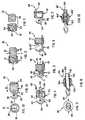
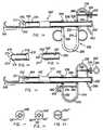
- a suture tie device 30in accordance with the present invention that includes a leg 32 having a preferably rigid proximal portions 34 of relatively large diameter and a distal tissue penetrating portion 36 of diminished diameter.
- proximaland variants thereof refers to the right hand side of a drawing
- distaland its variants refer to the left hand side of the drawing.
- the distal portion 36is provided with a suture needle or hook-like or curved configuration that terminates at a sharp distal end 38 and defines a tissue receiving space 39 having an open side adjacent distal end 38 that is positioned between the distal end 38 and the leg 32.
- the curved configuration of the distal tissue penetrating portion 36is similar to the configuration of a conventional suture needle and, preferably, is slender and configured so as to taper inwardly to a sharp point at its distal end 38.
- a locking/tying member 40at least partially, and preferably substantially, circumscribes the proximal portion 34 of the device 30 in a ring-like fashion.
- leg 32 and locking member 40can be completely or partially formed of a bioabsorbable or non-bioabsorbable material, or a combination thereof, which can be provided with appropriate physical characteristics so as to be entirely or partially rigid, semi-rigid or flexible, elastic, resilient or malleable in accordance with the suture tie device's 30 intended utilization.
- the locking member 40is preferably formed as a rigid or semi-rigid member and defines a passage 41 extending therethrough having an internal configuration or luminal surface that is configured to cooperate with a plurality of angled teeth 42 protruding from the outer surface of the leg 32 such that the locking member 40 is selectively displaceable only distally, in the direction of arrow A (Fig. 1), from the proximal end toward the distal end of leg 32.
- the interior surface of the locking member 40is preferably provided with a plurality of angled teeth 44 arranged at complementary angles to the angle of the teeth 42 of the leg 32 for engaging the leg teeth 42 to prevent proximal, i.e., rearward, movement of the locking member 40.
- the angled teeth 42can be disposed along the leg 32 in a variety of configurations, such as to extend from the entire or a predetermined portion of the peripheral surface of the leg, or so as to extend from a longitudinal recess or groove formed along the length of the leg 32.
- various configurationscan be utilized to permit only the distal movement of the locking member 40.
- Such movement-restricting configurationsinclude whisker-like filaments, barbs, ridges, angled pins or other protrusions which extend from the leg, some or all of which can be angled in the distal direction to prevent the proximal movement of a locking member 40.
- the suture tie device 30is held in a cradle of an applicator, examples of which are seen in Figs. 21, 23, 25, 27 and 29 and described in detail below, and manipulated in a manner similar to the movement of a conventional suture needle so as to extend the sharp distal end 38 of the device to penetrate tissue to be sutured, with or without the assistance in tissue penetration of the various suture tie device applicators described below.
- the tissue penetrating portion 36has been manipulated so as to extend through the tissue, the locking member 40 is displaced distally toward the distal end 38, as illustrated in Fig.
- the extent of distal movement of the locking member 40determines the size of the suture loop, the compression on the tissue sutured thereby, and ultimately completion of the tying of the suture loop.
- the degree of tension of the tiecan also be adjustable by the movement of the locking member distally from a position of initial approximation of the tissue structures to a position of full tying of the suture loop with maximum tension of the tie.
- the protruding proximal portion of the leg extending beyond the locking member 40can be severed, as shown by severing line "S" in Fig. 2, at an appropriate position to allow the tied suture loop to remain intact.
- the severed portion of the legcan thereafter be removed from the surgical site for disposal.
- a modified suture tie device 48 according to the present inventionis illustrated in Fig. 4.
- the modified device 48differs from suture tie device 30 depicted in Figs. 1-3 primarily in the configuration of the leg and locking member.
- the distal portion 50 of leg 52has more of a curved suture needle-like or hook-like configuration for grasping a larger amount of tissue, whereas the proximal portion 54 thereof is of comparatively smaller diameter.
- the locking member 56is provided with a central passage 58 therethrough having a plurality of angled teeth protruding therefrom to engage correspondingly-angled teeth 60 protruding from the leg.
- teeth-like coupling configurationscan be replaced with other types of protrusions or indentations which also inhibit or prevent undesired proximal movement of the locking member.
- a small recess 62can be provided at the upper, distal end of locking member 56 to receive the sharp distal end 64 of the tissue penetrating distal portion 50, while a larger recess 66 having a plurality of angled teeth or other suitable leg protrusion-engaging members 44 therealong to cooperate with and receive the angled teeth or other protruding members 60 along the curved distal portion can be provided at the lower of the locking member.
- the sharp distal point 64 of the suture tie devicecan be protected from exposure to surrounding structures, surgical instruments and the like by being received in recess 62, while recess 66 accommodates the curvature of the distal portion of the suture tie device to allow the movement of the locking member 56 therealong as desired to produce the desired degree of locking tension for tissue approximation and/or suture tying.
- the suture tie device 68 illustrated in Fig. 5is substantially similar to the embodiments described above and depicted in Figs. 1-4, with the exception that the proximal portion 70 of the tissue penetrating leg 72 is configured so as to extend through a passage 74 formed in the bottom of locking member 76.
- the locking memberis provided with a protruding portion 78 which extends outwardly from its distal face.
- the distal end of the protruding portion 78includes a recessed space 77 that is dimensioned to accommodate the curved distal portion 71 of the penetrating leg 72 and any tissue sutured thereby.
- a recess 80is formed in the member 76 to receive the sharp distal end 82 of the tissue penetrating distal portion 71 upon engagement of the distal portion with the locking member.
- the tissue receiving space 79is configured so as to be generally more open, i.e., less restricted by leg 70, than corresponding space 39 of the arrangement described in Figs. 1-4; however, the lateral, open sides of tissue receiving space 79 are likewise arranged so as to be selectively closable by the locking member 76 to tie the suture loop.
- the suture tie device 84 illustrated in Fig. 6depicts a further modification of the suture tie device of the subject application as depicted in Fig. 5, with the exception that the tissue penetrating leg 86 has a distal portion which can be provided with either a triangular 85 or rectangular 85' (depicted in phantom) cross-sectional configuration.
- the triangular configuration 85is preferred, for it provides for the secure grasping and suturing of a relatively greater amount of tissue.
- the distal face of the locking member 84can be provided with a variety of different configurations, such as with a generally planar face, as shown at 83', and optionally as with a recessed space 77 to accommodate the tissue sutured by distal portion 85'.
- the distal facecan be configured to provide a generally triangular or pyramidal protrusion 83 (depicted in phantom) that can optionally be provided with a recessed space 77 at the distal tip of protrusion 83 to accommodate the tissue sutured by angularly-configured distal portion 85.
- the suture tie device 88illustrated in Fig. 7, is similar to the suture tie device 48 depicted in Fig. 4 and described above, with the exception that the proximal portion 90 of the leg 32 passes through a passage 41 formed at the top of locking member 92 to create a relatively large, generally "C” or "V"-shaped space 91 in the curved suture needle-like, tissue-penetrating distal portion 94.
- a slight proximally-extending, needle-like protrusion 93extending from tissue-penetrating portion 94, a plurality of segments of tissue can be engaged within spaces 91 and 95 thereof and simultaneously tied by the distal movement of locking member 92 along leg 32 in the manner described above.
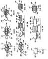
- the arrangement of the suture tie device 96 shown in Figs. 8 and 9provides a relatively elongated, narrow, hook-like tissue penetrating distal portion 98 with a relatively thick proximal leg portion 100.
- a longitudinal groove 101is disposed along the upper and lower length of the leg thereof within which are provided a plurality of slight ridges 102 and recesses 103 that are adapted to cooperate with the plurality of angled filaments 104 extending from the internal surface of the central passage of the locking member 106 so as to provide selectively actuable groove coupling means.
- the filamentsare angled such that the locking member can be selectively displaced in a distal direction only.
- Suture tie device 96is particularly useful for plugging or occluding holes in tissue or organ structures and for suturing damaged regions which are located in deep and/or narrow spaces, since the shape of the spaces defined by the distal tissue penetrating portion 98 is relatively narrow and ovate.
- suture tie device 96'can also be provided with a plurality of whisker-like filaments 105 on the surface of the leg 100 that are angled to cooperate with indentations, grooves, or micro-holes 104' formed along the interior of the passage of the locking member 106' to ensure unidirectional, distal movement of the locking member while preventing its proximal (backward) movement.
- Fig. 11shows a suture tie device modification 97 of the suture tie device 96 depicted in Figs. 8 and 9 that provides for bi-directional movement of the locking member along the leg of the device.
- the leg 100 of the deviceis configured as a generally hollow tubular member and is provided along its inner surface with a plurality of tooth-like protrusions 109.
- Mounted within the central passage 41 of the locking member 107is a pair of opposed, inwardly-protruding arms 111 which pass through longitudinal slots 113 formed along the upper and lower sides of the tissue penetrating leg 100.
- each arm 111Attached to the ends of each arm 111 is a plate 115 having a plurality of tooth-like protrusions 117 on the sides which face the protruding teeth 109 of the leg.
- the locking member 107is configured as an elastically-deformable member, and a predetermined amount of space is provided between the passage wall of the locking member and the outer surface of the penetrating leg 100 such that, when the locking member 107 is compressed along its upper and lower surfaces, the plate's teeth 117 disengage from the leg's inner teeth 109 to disengage the locking member from the leg to permit selective distal or proximal movement along the leg. However, once the locking member 107 is released, the plate's teeth 117 engage with the leg's internal teeth 109 such that the locking member is locked at that position.
- Fig. 12shows a modification 177 of the components for the bi-directionally operable locking member and leg-engaging-means described in Fig. 11, in which the hollow leg 100 of the suture tie device is provided with a plurality of microholes 123 along its interior surface.
- the locking member 125is provided with a pair of opposed arms 119 which protrude inwardly and pass through longitudinal slots 127 along the upper and lower sides of the leg of the suture tie device.
- Positioned at the free end of each armis one or more hook-like members 121 which cooperate with the microholes 123 of the leg to lock the locking member 125 in place on the leg.
- the member 125When the locking member is compressed as described above, the member 125 can be selectively displaced distally or proximally along the leg 100 to a desired position, where it can then be locked into position upon release of the locking member, thereby urging the hook-like members 121 to extend into the microholes 123 in the manner described above with the plate teeth 117 and leg internal teeth 109.
- Fig. 13shows suture tie device 129 in which the bi-directionally operable locking member 131 is provided with a pair of recesses 133 and 135 to accommodate distal penetrating portion 137 and sharp distal tip 139, respectively, when the locking member 131 is moved distally.
- a plurality of umbilicated grooves or ridges 145Positioned on the surface of the leg are a plurality of umbilicated grooves or ridges 145 which can cooperate with the ends of inwardly-extending pivoting bars 143 of the locking member 131.
- These pivoting bars 143extend outwardly from recess 41 to a pivoting point 141, which joins each pivoting bar 143 to a corresponding rigid bar 119' which extends from the interior surface of the device 131 into its internal passage 41.
- the pivoting bar 143is angled to an end which can cooperate with the grooves 145.
- bars 119'move inwardly, causing the angled bars 143 to collapse away from the leg by the pivot point to permit movement of the locking member in either direction, distally or proximally, until it reaches a desired position, at which point the locking member can be released and the pivoting bars 143 returned to their initial position with their ends locked within the grooves of the leg to lock the locking member in place along the leg.
- Fig. 14illustrates a modification 147 of suture tie devices 97 and 177, in which the bi-directionally operable locking member 149 is provided with a pair of opposed bilateral bars or rods 151 which protrude inwardly from plates 151'.
- Each bar or rod 151is provided with a longitudinally oriented plate or bar 153 having a plurality of hook-like members 155 which can cooperate with the microholes 123 formed in the leg of the device 147.
- the hollow leg of suture tie device 147is provided with a pair of bilateral slots 127 extending longitudinally to allow bilateral bars 151 of the locking member to move distally and proximally upon compression and advancement of the locking member.
- Microholes 123accommodate the hook-like members 155 when the locking member is released to lock the device 149 at a desired position along the surface of the leg 100.
- All of the locking members illustrated in Figs. 11-14are preferably made of a rigid or semi-rigid resilient or elastic bioabsorbable or non-bioabsorbable material to facilitate control of its distal and proximal movement.
- a further suture tie device arrangementis depicted at 108 in Fig. 15 and includes a tissue penetrating leg 110 having a polygonally-shaped distal tissue penetrating portion 112 which terminates at a sharp distal end 114 and a proximal shoulder 25, as shown in Fig. 15, or a tissue penetrating leg 110' having a generally rectangular distal tissue penetrating end 112' terminating at a sharp distal point 114 and proximal shoulder 25, as shown in Fig. 16.
- a locking member 116is provided with a passage 118 that extends through the bottom thereof for either leg 110 or 110', and a recess 120 at the top for receiving distal end 114 when the locking member 116 is moved distally to tie the suture loop. When the locking member 116 is utilized alone with either leg 110 or 110', the locking/tying member itself can be moved distally to tie the suture loop.
- locking member 116An alternative to using locking member 116 alone is to use a combination of locking member 116 in connection with a plug 122 with either leg 110 or 110'.
- the polygonally shaped distal end 126 of the plug 122corresponds to the polygonally-shaped distal portion 112 of leg 110, whereas the blunt distal end 126' (depicted in phantom) corresponds to the rectangular distal portion 112' for use therewith.
- the proximal portion of leg 110'passes through the lower passage 118 of locking member 116, which is provided with a relatively wide central passage 119 for receiving plug 122.
- a plurality of barbs 124, ridges, filaments, or microholescan be formed on the surface of plug 122 to correspond to protrusions along the internal surface of passage 119 to permit for selective displacement of the plug 122 only in the distal direction until its proximal shoulder 123 meets the proximal face of locking member 116, thereby tying the adjustable suture loop.
- both the plug 122 and the locking member 116provides both a proximal movement of leg 110 or 110' and a simultaneous distal movement of plug 122 in relation to locking member 116
- the cavities 118 and 119, as well as the leg and plug members 110, 122can be appropriately dimensioned such that simultaneous movement of the leg 110 and plug 122 toward each other allows the tightening of the plug and the leg, even in the absence of any coupling means on the surfaces of either the plug or the leg.
- a further arrangement for a suture tie device 128, illustrated in Fig. 17,includes a tubular or hollow tissue penetrating leg 130 which defines a cavity 131 and includes a distal tissue penetrating portion 132 terminating at an open sharp distal end 134 and an outwardly flared or tapered proximal shoulder 135.
- the locking member 136is provided with upper and lower passages 138 and 140, respectively, for receiving rigid or semi-flexible upper and lower arms 142 and 144 which extend in a distal direction from a push plate 146.
- the proximal shoulder 135 of the leg 130extends through the lower passage 140 of locking member 136 to prevent the leg 130 from passing distally outwardly therethrough.
- the arms 142 and 144have a diameter selected to permit them to be received within the respective passages 138 and 140 such that the distal end 134 of the leg 130 can be received into the distal end of arm 142' instead of receiving the distal end of arm 142 internally.
- the push plate 146is moved distally such that the distal portion of arm 142 or 142' enters or receives the distal end 134 of the leg 130, and the lower arm 144 passes through the lumen of leg 130 until plate 146 meets the proximal shoulder of leg 130, thereby completing a suture loop which can, thereafter, be adjusted in size by the movement of locking member 136 distally until the loop is ultimately tied and tensioned.
- one-way movement of the locking member 136can be effected by suitable coupling means as described above.
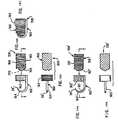
- a further configuration of a suture tie device 158is illustrated in Figs. 18A, 18B and 18C and includes a solid tissue penetrating leg 160 having a proximal ring 162 extending therefrom and a distal tissue penetrating portion 164 terminating at a sharp distal end 38'.
- a locking member 166is provided in the form of a plug which may have coupling members 168 such as angled teeth, ridges, or filaments extending therefrom for cooperating with a correspondingly-configured internal surface of a leg collar 162.
- a nib 170can be provided which extends from the upper end of the plug-like locking member 166 to overlie the sharp distal end 38' of the tissue penetrating portion 164.
- the plugoperates in a fashion similar to the ring-like locking members described above by passing through the collar 162, as illustrated in Figs. 18B and 18C, in a distal direction to a desired extent to capture tissue sutured by the tissue penetrating distal portion 164.
- a gently curved recess 165can optionally be formed along the curved convex distal end of locking member 166 to accommodate the sutured tissue or the curved distal portion 164 of leg 160 alone when plug 166 is moved distally through collar 162, as shown in Figs. 18B and 18C.
- the sharp distal end 38'is depicted as being completely covered by nib 170, and the curved distal portion 164 of leg 160 is received by the recess 165, as would occur upon complete distal advancement of the locking member 166 relative to the collar 162.
- Fig. 19shows a modification 158' of the suture tie device 158 shown in Fig. 18A, in which the cradle-like penetrating leg 160' is provided with a generally U-shaped or C-shaped cross-section to create a channel or space 161 for accommodating the suture tissue and/or to allow the passage of a length of suture material therethrough.
- the channel 161which is continuous with the central passage of the collar 162' located at the proximal end of leg 160'.
- the plug-like locking member 166'can be provided with a coupling configuration similar to that described in Fig. 18A.
- plug 166'can also be provided with a lumen or channel 167 which extends along the lower side, the distal curved end, and the upper side to provide for the passage of a length of suture material or medication therethrough.
- the curved suture needle-like or hook-like tissue penetrating distal portionscan be provided with a wide variety of configurations to define spaces therein of various shapes and configurations, such as circular, oval, rectangular, rhomboid and the like, for suturing various tissue and organ structures.
- the locking memberscan be arranged so as to be movable only distally along the tissue penetrating legs in a single direction only by means of various cooperating structures such as continuous or segmented barbs, angled teeth, whisker-like filaments, microholes for engagement by corresponding microfilaments and the like, or this one-way movement may be achieved by the use of umbilicated, thread-like ridges embedded in a groove extending along the length of the leg so as to engage and lock whisker-like filaments or angled pins or the like protruding from the internal surface of the locking member.
- various cooperating structuressuch as continuous or segmented barbs, angled teeth, whisker-like filaments, microholes for engagement by corresponding microfilaments and the like, or this one-way movement may be achieved by the use of umbilicated, thread-like ridges embedded in a groove extending along the length of the leg so as to engage and lock whisker-like filaments or angled pins or the like protruding from the
- the locking memberscan also be arranged so as to be bi-directionally displaceable along the legs either direction by having either through the provision of hollow penetrating legs with teeth or microholes or the like and longitudinal slots which allow for distal and proximal movement of the protruding arms of the locking members.
- the locking memberscan be provided with plates with teeth or hooks which correspond to the internal surface configurations of the legs, or with solid penetrating legs having grooves on the surface which cooperate with pivoting bars or rods extending from the internal passage of the locking members. Compression of these various locking members allows their distal or proximal movement, while their release locks the locking member in the desired position.
- the locking membersthemselves can also be provided with a wide variety of shapes and cross-sectional configurations.
- complementary recessescan be formed in the locking member to accommodate and cover the distal portion including the sharp distal end, and further to accommodate tissue penetrated by the distal end such that the tissue is held within the suture loop formed by the locking member and the tissue penetrating leg.
- the suturing procedureis essentially the same with all of the embodiments in that a suturing maneuver is made with the distal end of the suture tie device alone or in conjunction with the distal end of an applicator as described below to penetrate the tissue, and a looping operation is provided by moving the locking member distally a desired extent until the suture loop is completely tied around the sutured tissue.
- the configuration of the locking member(for example, a ring-like or plug-like member) can be provided with a distal face having a configuration to accommodate the tissue as well as the sharp edges of the distal portion of the tissue penetrating leg.
- the sharp distal endcan be disposed within the locking member in accordance with the tissue or organ structure to be sutured and its position in the body.
- the suture tie devices described aboveare preferably and advantageously made of bioabsorbable material
- the suture tie devicescan be made in whole or in part of partially bioabsorbable or non-bioabsorbable material, if desired.
- the locking memberscan be configured so as to be rigid or resilient depending on the arrangement of the locking and coupling means.
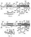
- an applicator 172comprised generally of two tubular members: a cartridge member 174 and an outer tubular member 206 having a tubular lumen for receiving the cartridge member.
- the applicator 172allows for the application of the various suture tie devices described above and depicted in Figs. 1-19 in accordance with the present invention.
- Fig. 21Ashows the distal portion of only the outer tubular member 206 with its hook-like cradle 208 for receiving one of the suture tie devices 48 for application to tissue in the manner described in detail below.
- the cartridge 174which is shown in further detail in Figs. 21B and 21C, is a spring-loaded member which houses a plurality of suture tie devices, such as the suture tie device 48 shown in Fig. 4, in an end-to-end serial arrangement.
- the cartridge 174includes an outer tubular member 176 having a cap 178 at its proximal end with an extendable rod 180 passing through an opening in cap 178 and terminating at its proximal end at an actuator button 182 and at its distal end at a pusher member 184 having a recess therein adapted to receive the proximal end of the last (i.e., most proximally positioned) of the plurality of suture tie devices 48.
- Various meanscan be provided for the extending mechanism of the rod 180, some of which are shown in Figs. 21C, 21D and 21E.
- the rod 180can be configured as two or more concentrically-arranged tubular members 180a, 180b which have cooperating configurations for extending the length of the rod and locking it at a selected length such that a single suture tie device can be released in a one-by-one fashion.
- one of the outer or inner concentrically-arranged rods 180a, 180bcan be provided with a plurality of one-way angled filaments or pins 181, and the other of the tubular members can be provided with corresponding umbilicated threaded grooves or ridges 183, as shown in Figs. 21C and 21D.
- the rods 180a and 180bcan be provided with correspondingly-threaded surfaces 185, as shown in Fig. 21E, to ensure displacement in the desired direction.
- a helical spring 186is mounted in a displaceable housing 187 in compression between actuator button 182 and cap 178.
- a biasing means 188such as helical spring member, which is mounted in compression between the proximal end of the tubular member 176 and pusher member 184.
- the distal end of the cartridge 176is slotted to define two or more expandable arms 190 and 192, as seen frontally in Fig. 21B.
- the armsterminate at ends 194 and 196, respectively, and are each provided with a generally curved configuration which can be varied in shape to accommodate the curved shape of the distal penetrating portion of the various suture tie devices shown in Figs. 1-19.
- a generally U-shaped or C-shaped handle 198is provided for controlling operation of the applicator device 172.
- the handle 198includes proximal and distal arms 199 and 200 joined to one another by curved spring portion 201.
- the proximal handle arm 199terminates at a collar 214 secured to the tubular member 176 that is telescopically received within outer member 206.
- the distal handle arm 200terminates at a collar 204 that is secured to the proximal end of the outer tubular member 206 of the applicator 172 that, in turn, is attached at the bottom of its distal end to the fixed, hook-like cradle 208.
- the cradle 208is provided with a curved distal portion which terminates at distal end 210 that can be configured in a variety of shapes so as to correspond to the configuration of the distal portion of the leg of the particular arrangement of suture tie device to be used with the applicator.
- the distal end 210 of the outer tubular membercan be configured so as to correspond to the length of the distal end 64 of the suture tie device 48, or it can be provided with a length that is slightly longer than the suture tie device 48 and a configuration which permits it to function as a tissue penetrating member.
- the distal end 210is provided with a sharp distal edge to facilitate suturing.
- the distal end 210can be provided with a length that is slightly shorter than that of the suture tie device 48, so that the distal end 64 of the device 48 functions as the tissue penetrating member.
- a cartridge 174is pre-mounted within applicator 172 or inserted through the open proximal end of the applicator upon removal of the cap 178, and the applicator is inserted through an incision or portal formed in the exterior surface of the body of a patient and advanced to a suturing site.
- actuating button 182By depressing actuating button 182, extendable rod 180 with pusher member 184 is advanced distally to urge a suture tie device distally so as to expand the cartridge arms 190 and 192 from one another and exit the cartridge to be received in the cradle 208.
- the arms 190 and 192return to their generally closed (rest) position such that a space remains between arm distal ends 194 and 196 that is wide enough to allow the proximal portion of the leg of the suture tie device to pass therethrough, thereby allowing the distal ends 194 and 196 to be in position to push the locking member distally.
- the tissue to be suturedcan be penetrated by one or both of the (sharpened) distal ends of the suture tie device and the sharp distal point 210 of cradle 208.
- handle arms 199 and 200are squeezed toward one another a predetermined distance to distally advance the cartridge arm distal ends 194 and 196 against the locking member, thereby advancing the locking member distally.
- the locking member of the devicesuch as member 56 of the device 48, can be advanced toward the distal end 64 a desired amount to complete a suture loop and capture the sutured tissue therebetween.
- the handlecan be released and the applicator appropriately manipulated so as to deposit the suture tie device in place. Excess material of the suture tie device extending proximally of the locking member can be severed with a conventional forceps instrument.
- FIG. 22An alternative arrangement of a concentrically-arranged multi-tubular applicator 218 for applying suture tie devices according to the present invention is illustrated in Fig. 22.
- Parts of the applicator 218 that are identical or corresponding to parts of applicator 172are designated by identical reference numbers and are not described again for the sake of brevity.
- the extendable rod 180can be configured as two or more concentrically-arranged tubular members, as described above in connection with Figs. 21C-21E, and can be moved distally and proximally in relation to one another such that the length of the entire rod extends automatically after each suture tie device is sequentially released from the cartridge.
- Applicator 218is substantially similar structurally and functionally to applicator 172 (Fig.
- tubular member 176 of the cartridgeterminates at a blunt, open distal end 220
- outer tubular member 206terminates at its distal end at a plurality of slotted, multiple curved arms 222.
- the arms 222can be configured so as to accommodate the curved distal portion of the various types of suture tie devices described above and depicted in Figs. 1-19.
- the guides 224which are preferably arranged as opposed, distally-angled pairs extending toward the interior of the cartridge member, are provided with generally concave end surfaces (Fig. 23B) to align the suture tie devices so that the arms can collapse against the internal wall of the cartridge tubular member 176, as indicated by the arrows in Fig. 23C, to allow the suture tie devices to be released from the cartridge in a sequential manner.
- the distal-most guides 224a(Fig. 23C) extend distally beyond the blunt distal end of cartridge member 176 and serve to push the locking/tying member of the released suture tie device in the distal direction to complete the tying process.
- applicator 218Use of the applicator 218 is similar to that described above with respect to applicator 172, in which a suture tie device can be released into the cradle 208 by compressing button 182 toward cap 178.
- the (inner) tubular member 176can be rotated in relation to (outer) tubular member 206, or vice versa, to release a suture tie device into the cradle 208.
- Another applicator arrangementprovides that displacement of handle arms 199 and 200 toward one another upon squeezing of the handle 198 directs the blunt distal end 220 and the distal-most guide 224a of the cartridge to expand the arms 222 of the outer tubular member.
- an independent forcep assemblysuch as a biopsy instrument, can be passed through outer tubular member 206 to sever the portion of the suture tie device protruding proximally of the locking/tying member.
- FIGs. 24 and 25A further arrangement for an applicator 226 is illustrated in Figs. 24 and 25 and is comprised of three concentrically-arranged tubular members, one of the tubular members being a cartridge member 228 for housing a plurality of suture tie devices of the type described above and depicted in Figs. 1-19 that are serially arranged and spring biased distally by a compression spring 188 in a manners similar to that described above in connection with the cartridge members for the applicators 172 and 218 depicted in Figs. 20 and 22.
- the distal portion of the cartridge tubular member 230is provided with a flat, blunt distal end, whereas the distal portion of intermediate tubular member 236 is depicted as having curved expandable arms 240.
- the cartridge 228, as shown in Fig. 25,includes a tubular member 230 having a cap 232 at its proximal end and an open distal end 234.
- An intermediate tubular member 236circumscribes the cartridge tubular member 230 and is positioned between tubular member 230 and an outer tubular member 242. A proximal end of the intermediate tubular member is secured to a collar 238.
- the intermediate tubular member 236includes at least one pair of expandable curved arms 240 at its distal end which can be configured in accordance with the type of suture tie device used.
- the outer tubular member 242is provided with a proximal end that is secured to a collar 244, and a distal end that is configured as a fixed, hook-like cradle 246.
- the cradlehas a generally U-shaped or C-shaped cross-sectional configuration and terminates at a sharp point 248.
- a U-shaped handle 250comprising distal and proximal arms 252 and 254 joined to one another by a curved spring portion 255 is arranged such that a distal arm 252 is secured to collar 244 and a proximal arm 254 is secured to collar 238.
- Ring handles 256a and 256bcan optionally be provided along arms 252 and 254, respectively, to facilitate handle grasping and operation.
- a second curved spring member 258connects collar 238 with a collar 259 that is secured to tubular member 230 of the cartridge 228 such that the inner tubular member 230 and intermediate tubular member 236 can move together to move the curved distal end 240 of the cartridge not only to distally advance the locking member of the suture tie device, but optionally to move or manipulate the proximal portion of the suture tie device leg for a severing action or to hold or manipulate the locking member at a desired position.
- a finger grip 260extending downwardly from the collar 259 and spring member 258 can optionally be provided to facilitate spring member manipulation.
- a cartridge 228 housing a plurality of suture tie devicesis loaded in the applicator 226.
- spring member grip 260 and arm 254 of handle 250are urged toward one another, thereby moving tubular member 230 distally relative to intermediate tubular member 236, causing distal end 234 to open or expand arms 240 and allowing the spring bias within the cartridge to push the distal-most suture tie device beyond the expanded arms 240 and into cradle 246.
- the grip 260is released, the curved arms 240 return to their rest, generally closed position due to the bias from spring member 258 to restrict further distal movement of the remaining suture tie devices in the applicator.
- the desired tissue or organ structurecan be sutured by penetrating the tissue with at least one of the sharp distal ends of the hook-like cradle and the suture tie device in a conventional suture needle-like fashion.
- arms 252 and 254 of handle 250are urged toward one another to an extent selected by the user, thereby moving intermediate tubular member 236 distally relative to outer tubular member 242 and causing the ends of curved cartridge arms 240 to move the locking member distally so as to accomplish the suture tying function at a desired level of suture tension.
- the handle 250is released and the applicator is maneuvered so as to allow the tied suture tie device to be released from the applicator 226. Since a plurality of suture tie devices are preferably supplied in the cartridge, continuous (i.e., sequential and uninterrupted) suturing procedures can be accomplished without withdrawing the applicator from the surgical suture site.
- Figs. 26 and 27illustrate an applicator 286 that represents a modification of the applicator 226 depicted in Fig. 24, in which similar components have been provided with identical reference numbers.
- an inner cartridge tubular member 272is provided having a curved distal end 274.
- a spring-loaded cylinder 255is provided which extends proximally from collar 238 to a shoulder 257 which is positioned adjacent to shoulder 273 of the inner cartridge tubular member 272 and houses a coiled spring 290 or other suitable biasing means.
- the cylinder 255functions in a manner similar to the curved spring member 258 of applicator 226 by providing a means for displacing the inner and intermediate tubular members together distally. It will be appreciated, therefore, that the respective cylinder 255 and spring member 258 configurations can be interchangeable for applicators 226 and 286.
- Fig. 28Illustrated in Fig. 28 is an applicator 262 that represents a further modification of the applicator 226 depicted in Fig. 24 that is particularly useful for adjusting the separation distance between the curved distal portion of various tubular member configurations for severing or manipulating protruding proximal portions of suture tie devices after suturing and tying.
- applicator 226parts thereof which correspond to parts of applicator 262 are identified by like reference numerals and are not repetitively described.
- the spacing adjustment mechanism of applicator 262is provided to control the spacing between the ends of curved arms 240 of the intermediate tubular member 236.
- the spacing adjustment mechanism 266includes a threaded rod 268 having an end secured to the distal portion of curved spring member 258 adjacent collar 238.
- the rod 268extends through a passage 258a formed in the proximal portion of spring 256 to protrude therefrom and threadably receive an adjustment nut 270.
- Operation of the applicator 262is implemented by squeezing the handgrip 260 relative to arm 254 of handle 250, thereby advancing the distal-most suture tie device into position in the cradle 246 in the manner described above with respect to applicator 226.
- the curved arms 240return to their locking member-pushing position when the grip 260 is released.
- Suturingcan be accomplished in a manner similar to that obtained from use of a conventional curved suture needle, in which the tissue is penetrated by a curved insertion motion of the distal end of the applicator 262.
- Rigid tethers 264connect the distal end 234 of the cartridge tubular member 230 with the distal end 240 of the intermediate tubular member.
- Distal and proximal movement of the cartridge tubular member 230effects approximation and withdrawal, respectively, of the distal tips 271 by way of the tethers 264.
- nut 270 of the spacing adjustment mechanismcan be rotatably adjusted until it reaches the proximal end of the threaded rod 268, thereby urging distal curved arms 240 towards one another to position the distal ends 271 thereof in close proximity to one another to, for example, grasp the end of the length of suture material, abut the proximal end of the plug of a suture tie device, or to grasp and/or sever the proximal portion of any other various type of suture tie device such as those shown in Figs.
- the nut 270is rotated back to its rest position to open the distal ends 271 and return them to their locking member-pushing position.
- Handle 250can then be squeezed further together to advance the locking member distally to complete the tying operation. Once the tying operation has been completed, the handle is released and the tied suture tie device can be released from the applicator 262.
- FIG. 29A further alternative arrangement for an applicator 277 that is a modification of applicator 262 of Fig 28 is illustrated in Fig. 29, where parts of applicator 277 identical to parts of applicator 262 are provided with identical reference numbers.
- Applicator 277is substantially similar to applicator 262, with the exception that applicator 277 includes a means 269' for positioning the curved distal end of the distal portions of the inner and intermediate members at a desired position for any severing, compressing, or manipulating action that may be required incident to the handling of a particular configuration and type of suture tie device used therewith.
- the positioning means 269'includes a rod 278 having a proximal end rotatably mounted to handle arm 254, a finger grip 280 at the distal end of the rod, and angled teeth 282 protruding from the rod along the length thereof.
- the rod 278extends through an opening 279 formed in arm 252 of the handle and is operable in cooperation therewith to lock the position of the handle arms 252 and 254 in a predetermined spatial relationship. In use, the rod 278 can be rotated and locked in position to allow precise positioning of the distal ends 271 of the curved arms 240 of the tubular member 236 prior to the aforedescribed severing operation.
- tissue or organ structurecan be penetrated by at least one of the distal ends of the suture tie device and cradle.
- the handle 250can be squeezed to direct movement of cartridge arms 240 to move the locking member distally to accomplish the locking function.
- the handle 250can be manipulated so as to position the distal ends 271 along the proximal portion of the suture tie device to the desired position for severing the proximal portion of the suture tie device, and the position of the handle 250 can be fixed by rotatably adjusting the position of the rod 278 so that the teeth 282 can engage the handle opening 279.
- the nut 270 of the spacing adjustment mechanism 266'can be rotated until it abuts ring handle 284, thereby directing rigid tethers 264 to pull arms 240 together to sever the proximal portion of the suture tie device at the desired point.
- the rod 278can be released, and the screw 270 moved back to its rest position to permit the tied suture tie device to be released from the applicator.
- Fig. 30shows the inner tubular member 272 as having a distal curved portion 274 that is provided with sharp severing ends 273, and the intermediate tubular member 276 as having a blunt distal end.
- the distal portion 274can be provided with a variety of configurations as well so as to accommodate the structure of the specific suture tie device to be used.
- Fig. 31shows a distal face 240' for pushing the locking members of a wide variety of the various suture tie devices shown in Figs. 1-19.
- the distal faceincludes an indented portion 241' which can be provided with a sharp severing edge for severing the proximal portion of the legs after the tying process is complete.
- Fig. 32shows the distal face 240'' which is arranged to push the locking member specifically of suture tie device 148 after distal face indentations 241'' engage and advance the suture material 154 or 154' distally to circulate through the leg 150 of the device 148.
- These indentations 241''can also be provided with a sharp edged for severing the protruding proximal portion of the suture material.
- the central indentation 241'can include a severing edge which allows the configuration of Fig. 32 to also be used with various other suture tie devices of Figs. 1-19.
- Fig. 34illustrates an arrangement in which an inner tubular member 230' is provided with a straight distal portion with longitudinal slots 265' for allowing the distal and proximal movement of the curved distal portions 240' of intermediate tubular member 236'.
- the distal tips 271'if sharpened, provide a severing action, and if blunt, provide a grasping, manipulating and/or compressing action.
- the distal blunt ends 233'can be positioned specifically for the suture tie devices of Figs. 16-19.
- Indentations 231can be shaped to accommodate either the curved needle portion of the various suture tie devices or the various locking/tying members, and can be disposed along the inner surface of the innermost tubular member of any of the configurations described for the various applicators. These indentations can function in a manner analogous to the guides 224 depicted in Figs. 23B and 23C to hold and space apart accordingly the suture tie devices within the cartridge.
Landscapes
- Health & Medical Sciences (AREA)
- Surgery (AREA)
- Life Sciences & Earth Sciences (AREA)
- Heart & Thoracic Surgery (AREA)
- Molecular Biology (AREA)
- Veterinary Medicine (AREA)
- Engineering & Computer Science (AREA)
- Biomedical Technology (AREA)
- Public Health (AREA)
- Medical Informatics (AREA)
- Nuclear Medicine, Radiotherapy & Molecular Imaging (AREA)
- Animal Behavior & Ethology (AREA)
- General Health & Medical Sciences (AREA)
- Reproductive Health (AREA)
- Vascular Medicine (AREA)
- Surgical Instruments (AREA)
- Load-Engaging Elements For Cranes (AREA)
Abstract
Description
Claims (13)
- A suture tie device for suturing bodily tissue,comprisinga single leg member having a proximal portion and adistal portion that includes a tissue-engaging portionterminating at a distal end, andlocking means, for engaging the distal end to form asuture loop, characterised in that the locking means isselectively displaceable along the leg member, in adirection toward the distal end.
- A device according to claim 1, further comprisingcoupling means for inhibitingat least proximal movement of the locking means, and wherein thelocking means is preferably selectively manipulable torelease the coupling means to permit displacement of thetying means along the leg member.
- A device according to claim 2, wherein the lockingmeans comprises a locking member having an aperture formedtherein for receiving the leg member, and the couplingmeans comprises a plurality of engaging members formedalong at least one of the leg member and the lockingmember.
- A device according to claim 3, wherein the engagingmembers are formed along a section of an exterior surfaceof the leg member and along an inner surface of theaperture in the locking member, the engaging memberspreferably comprising a plurality of angularly-extendingteeth; of filaments; of outwardly-extending ridges; ofridges and recesses arranged in an alternatingconfiguration; or of micro-holes formed along one of theleg member and the locking member aperture, and at leastone filament formed on the other of the leg member andlocking member aperture.
- A device according to claim 3 or claim 4, wherein theleg member is configured as a generally tubular member having a wall which defines a tubular lumen and a generallylongitudinally-extending slot extending between the tubularlumen and an exterior surface of the leg member, andwherein the locking member comprises an arm thatextends through the slot.
- A device according to any of claims 3 to 5, whereinthe leg member defines a cavity at its proximal portion andoptionally also an opening at its distal end, and thelocking member further comprises a second apertureaxially aligned with a tip of the leg member distal end orwith the opening.
- A device according to claim 6, further comprising aplug member comprising first and second arms extendingoutwardly from a plate member and being insertable throughcorresponding ones of the locking member apertures,the first arm being dimensioned so as to be received withinthe leg member cavity and the second arm either defining anarm cavity that is dimensioned to be received within thedistal end of the leg member or being dimensioned so as tobe insertable in the leg member distal end opening.
- A device according to claim 2, whereinthe proximal portion of the leg member comprises a collarmember defining a collar aperture having a plurality ofengaging members mounted along an interior surface of thecollar aperture, and the tying means comprises a plugmember insertable through the collar aperture, the plugmember being provided with a plurality of engaging membersfor interacting with the engaging members of the collaraperture.
- A suture tie device according to any of claims 1 to 5 and 7,wherein the proximal portion of the leg member isconfigured so as to be severable from the remainder of thedevice.
- An applicator for suturing tissue at a surgical suturesite with a suture tie device as defined in any of claims 1 to 9,the applicator comprising:an elongate outer member having a proximal portion anda distal portion for holding a suture tie device in atissue-suturing position;means for storing a plurality of suture tie devices;means for engaging the locking member of thesuture tie device;handle means connected with the proximal portion ofthe outer elongate member and the engaging means forselectively advancing the engaging means distally relativeto the outer elongate member to advance the lockingmember along the tissue-engaging leg member to effectsuturing; andactuator means for delivering a suture tie device fromthe storing means to the distal portion of the outerelongate member, whereby a plurality of suture tie devicescan be placed in the tissue without removing the applicatorfrom the surgical suture site.
- An applicator according to claim 10, wherein thestoring means comprises a housing for storing a pluralityof suture tie devices in an end-to-end serial arrangementand means for retaining the suture tie devices in thehousing, said retaining means being selectivelydisplaceable relative to a distal end of the storing meansto permit release of a suture tie device of the outerelongate member; the housing preferably has a generallytubular configuration, the actuator means being disposedadjacent the housing's proximal end and the retaining meansbeing disposed adjacent the housing's distal end; theretaining means preferably includes at least two radially-displaceablearms which extend from the housing distal endor from the outer elongate member adjacent the distal portion thereof; and the retaining means preferablycomprises at least one resilient guide member disposed inthe housing.
- An applicator according to claim 11, wherein thehousing comprises two coaxially-arranged generally elongatemembers, of which one has at least two radially-expandablearms extending from a distal end of the elongate member,and the other includes means for manipulating the radially-expandablearms, and wherein the actuator means is operableto effect distal and proximal movement of the elongatemembers relative to one another.
- An applicator according to claim 12, wherein ends ofthe radially-expandable arms are provided with sharp edgesfor severing a portion of the tissue-engaging leg.
Priority Applications (2)
| Application Number | Priority Date | Filing Date | Title |
|---|---|---|---|
| EP95118445AEP0701796A2 (en) | 1989-12-15 | 1990-12-14 | Suture tie device |
| EP95118448AEP0701797A2 (en) | 1989-12-15 | 1990-12-14 | Suture tie device |
Applications Claiming Priority (3)
| Application Number | Priority Date | Filing Date | Title |
|---|---|---|---|
| US450301 | 1989-12-15 | ||
| US07/450,301US5100418A (en) | 1987-05-14 | 1989-12-15 | Suture tie device system and applicator therefor |
| PCT/US1990/007237WO1991008708A1 (en) | 1989-12-15 | 1990-12-14 | Suture tie device system and applicator therefor |
Related Child Applications (1)
| Application Number | Title | Priority Date | Filing Date |
|---|---|---|---|
| EP95118445ADivisionEP0701796A2 (en) | 1989-12-15 | 1990-12-14 | Suture tie device |
Publications (3)
| Publication Number | Publication Date |
|---|---|
| EP0504312A1 EP0504312A1 (en) | 1992-09-23 |
| EP0504312A4 EP0504312A4 (en) | 1992-11-04 |
| EP0504312B1true EP0504312B1 (en) | 1998-03-18 |
Family
ID=23787548
Family Applications (3)
| Application Number | Title | Priority Date | Filing Date |
|---|---|---|---|
| EP95118448AWithdrawnEP0701797A2 (en) | 1989-12-15 | 1990-12-14 | Suture tie device |
| EP95118445AWithdrawnEP0701796A2 (en) | 1989-12-15 | 1990-12-14 | Suture tie device |
| EP91902462AExpired - LifetimeEP0504312B1 (en) | 1989-12-15 | 1990-12-14 | Suture tie device system and applicator therefor |
Family Applications Before (2)
| Application Number | Title | Priority Date | Filing Date |
|---|---|---|---|
| EP95118448AWithdrawnEP0701797A2 (en) | 1989-12-15 | 1990-12-14 | Suture tie device |
| EP95118445AWithdrawnEP0701796A2 (en) | 1989-12-15 | 1990-12-14 | Suture tie device |
Country Status (7)
| Country | Link |
|---|---|
| US (1) | US5100418A (en) |
| EP (3) | EP0701797A2 (en) |
| JP (1) | JPH05505732A (en) |
| AT (1) | ATE164053T1 (en) |
| DE (1) | DE69032165T2 (en) |
| ES (1) | ES2112858T3 (en) |
| WO (1) | WO1991008708A1 (en) |
Families Citing this family (334)
| Publication number | Priority date | Publication date | Assignee | Title |
|---|---|---|---|---|
| US5478353A (en)* | 1987-05-14 | 1995-12-26 | Yoon; Inbae | Suture tie device system and method for suturing anatomical tissue proximate an opening |
| US5437680A (en)* | 1987-05-14 | 1995-08-01 | Yoon; Inbae | Suturing method, apparatus and system for use in endoscopic procedures |
| US5100420A (en)* | 1989-07-18 | 1992-03-31 | United States Surgical Corporation | Apparatus and method for applying surgical clips in laparoscopic or endoscopic procedures |
| US5383881A (en) | 1989-07-18 | 1995-01-24 | United States Surgical Corporation | Safety device for use with endoscopic instrumentation |
| FR2640131B1 (en)* | 1988-12-12 | 1991-03-29 | Ethnor | LIGATURE ASSEMBLY FOR ENDOSCOPIC SURGERY, LIGATURE AND LIGATURE HANDLING INSTRUMENT FOR SUCH ASSEMBLY |
| US5382254A (en) | 1989-07-18 | 1995-01-17 | United States Surgical Corporation | Actuating handle for surgical instruments |
| US5665100A (en)* | 1989-12-05 | 1997-09-09 | Yoon; Inbae | Multifunctional instrument with interchangeable operating units for performing endoscopic procedures |
| US5984939A (en)* | 1989-12-05 | 1999-11-16 | Yoon; Inbae | Multifunctional grasping instrument with cutting member and operating channel for use in endoscopic and non-endoscopic procedures |
| US5797958A (en)* | 1989-12-05 | 1998-08-25 | Yoon; Inbae | Endoscopic grasping instrument with scissors |
| US5797939A (en)* | 1989-12-05 | 1998-08-25 | Yoon; Inbae | Endoscopic scissors with longitudinal operating channel |
| US5156609A (en)* | 1989-12-26 | 1992-10-20 | Nakao Naomi L | Endoscopic stapling device and method |
| US5366462A (en)* | 1990-08-28 | 1994-11-22 | Robert L. Kaster | Method of side-to-end vascular anastomotic stapling |
| US5171249A (en)* | 1991-04-04 | 1992-12-15 | Ethicon, Inc. | Endoscopic multiple ligating clip applier |
| US5242456A (en)* | 1991-11-21 | 1993-09-07 | Kensey Nash Corporation | Apparatus and methods for clamping tissue and reflecting the same |
| US5281236A (en)* | 1992-06-23 | 1994-01-25 | Boston Scientific Corporation | Method and device for intracorporeal knot tying |
| US5354304A (en)* | 1992-10-13 | 1994-10-11 | American Cyanamid Co. | Modular ligation clip applicator |
| US5306283A (en)* | 1992-06-30 | 1994-04-26 | American Cyanamid Company | Two-part surgical ligation clip |
| US5334199A (en)* | 1992-08-17 | 1994-08-02 | Inbae Yoon | Ligating instrument and methods of ligating tissue in endoscopic operative procedures |
| CA2104345A1 (en)* | 1992-09-02 | 1994-03-03 | David T. Green | Surgical clamp apparatus |
| US5578044A (en)* | 1992-09-04 | 1996-11-26 | Laurus Medical Corporation | Endoscopic suture system |
| US7060077B2 (en) | 1992-09-04 | 2006-06-13 | Boston Scientific Scimed, Inc. | Suturing instruments and methods of use |
| US6048351A (en) | 1992-09-04 | 2000-04-11 | Scimed Life Systems, Inc. | Transvaginal suturing system |
| US5540704A (en)* | 1992-09-04 | 1996-07-30 | Laurus Medical Corporation | Endoscopic suture system |
| US5364408A (en)* | 1992-09-04 | 1994-11-15 | Laurus Medical Corporation | Endoscopic suture system |
| US5713910A (en)* | 1992-09-04 | 1998-02-03 | Laurus Medical Corporation | Needle guidance system for endoscopic suture device |
| US5573169A (en)* | 1992-10-02 | 1996-11-12 | United States Surgical Corporation | Apparatus for applying two-part surgical fasteners in laparoscopic or endoscopic procedures |
| US5423471A (en)* | 1992-10-02 | 1995-06-13 | United States Surgical Corporation | Apparatus for applying two-part surgical fasteners in laparoscopic or endoscopic procedures |
| USD349339S (en) | 1992-10-05 | 1994-08-02 | Ethicon, Inc. | Surgical adhesion barrier applicator |
| US5292327A (en)* | 1992-10-08 | 1994-03-08 | Dodd Joseph T | Surgical knot pusher |
| US5300081A (en) | 1992-10-09 | 1994-04-05 | United States Surgical Corporation | Surgical clip applier having clip advancement control |
| US5403346A (en)* | 1992-12-31 | 1995-04-04 | Loeser; Edward A. | Self-affixing suture assembly |
| US5632753A (en)* | 1992-12-31 | 1997-05-27 | Loeser; Edward A. | Surgical procedures |
| US5382255A (en) | 1993-01-08 | 1995-01-17 | United States Surgical Corporation | Apparatus and method for assembly of surgical instruments |
| DE69403271T2 (en)* | 1993-04-27 | 1997-09-18 | American Cyanamid Co | Automatic laparoscopic applicator for ligation clips |
| US5431668A (en)* | 1993-04-29 | 1995-07-11 | Ethicon, Inc. | Ligating clip applier |
| DE4319829C1 (en)* | 1993-06-16 | 1994-08-25 | Lerch Karl Dieter | Set for treating vascular deformities |
| US5454820A (en)* | 1993-07-14 | 1995-10-03 | Ethicon, Inc. | Method of tying knots using a tube knot applicator |
| US5437682A (en)* | 1993-07-20 | 1995-08-01 | Ideas For Medicine, Inc. | Medical knot tying instrument and method for use thereof |
| US5405354A (en)* | 1993-08-06 | 1995-04-11 | Vance Products Inc. | Suture driver |
| US5607436A (en)* | 1993-10-08 | 1997-03-04 | United States Surgical Corporation | Apparatus for applying surgical clips |
| GB9405790D0 (en)* | 1994-03-23 | 1994-05-11 | Univ London | Sewing device |
| JP3526609B2 (en)* | 1994-03-31 | 2004-05-17 | テルモ株式会社 | Suture instrument |
| US5833695A (en)* | 1994-07-13 | 1998-11-10 | Yoon; Inbae | Surgical stapling system and method of applying staples from multiple staple cartridges |
| WO1996009797A1 (en)* | 1994-09-28 | 1996-04-04 | Innovasive Devices, Inc. | Suture tensioning device |
| US5620452A (en)* | 1994-12-22 | 1997-04-15 | Yoon; Inbae | Surgical clip with ductile tissue penetrating members |
| US5665109A (en)* | 1994-12-29 | 1997-09-09 | Yoon; Inbae | Methods and apparatus for suturing tissue |
| US5643295A (en) | 1994-12-29 | 1997-07-01 | Yoon; Inbae | Methods and apparatus for suturing tissue |
| US5665096A (en)* | 1995-03-07 | 1997-09-09 | Yoon; Inbae | Needle driving apparatus and methods of suturing tissue |
| US5695505A (en)* | 1995-03-09 | 1997-12-09 | Yoon; Inbae | Multifunctional spring clips and cartridges and applicators therefor |
| US5935149A (en)* | 1995-06-07 | 1999-08-10 | Smith & Nephew Inc. | Suturing tissue |
| US5730747A (en)* | 1995-06-07 | 1998-03-24 | Smith & Nephew, Inc. | Suture passing forceps |
| DE19534323A1 (en)* | 1995-09-15 | 1997-03-20 | Aesculap Ag | Clamping ring for a surgical clip |
| US5693059A (en)* | 1995-09-15 | 1997-12-02 | Yoon; Inbae | Ligating instrument with multiple loop ligature supply and methods therefor |
| US5704943A (en)* | 1995-09-25 | 1998-01-06 | Yoon; Inbae | Ligating instrument with multiple loop ligature supply and methods therefor |
| US5810853A (en)* | 1996-01-16 | 1998-09-22 | Yoon; Inbae | Knotting element for use in suturing anatomical tissue and methods therefor |
| US5741276A (en)* | 1996-03-28 | 1998-04-21 | Innovative Surgical Instruments | Apparatus for facilitating the performance of surgical procedures such as the placement of sutures, ligatures and the like |
| US5833696A (en) | 1996-10-03 | 1998-11-10 | United States Surgical Corporation | Apparatus for applying surgical clips |
| US5879371A (en)* | 1997-01-09 | 1999-03-09 | Elective Vascular Interventions, Inc. | Ferruled loop surgical fasteners, instruments, and methods for minimally invasive vascular and endoscopic surgery |
| US5928252A (en)* | 1997-01-21 | 1999-07-27 | Regen Biologics, Inc. | Device and method for driving a needle and meniscal repair |
| WO1998031288A1 (en)* | 1997-01-21 | 1998-07-23 | Regen Biologics, Inc. | Device and method for driving a needle and meniscal repair |
| US5947982A (en)* | 1997-04-02 | 1999-09-07 | Smith & Nephew, Inc. | Suture-passing forceps |
| GB9722203D0 (en)* | 1997-10-21 | 1997-12-17 | Univ London | Surgical clip |
| AU3967499A (en)* | 1998-04-30 | 1999-11-16 | Inbae Yoon | Multiple needle suturing instrument and method |
| US6945980B2 (en) | 1998-06-03 | 2005-09-20 | Medtronic, Inc. | Multiple loop tissue connector apparatus and methods |
| US6613059B2 (en) | 1999-03-01 | 2003-09-02 | Coalescent Surgical, Inc. | Tissue connector apparatus and methods |
| US6607541B1 (en)* | 1998-06-03 | 2003-08-19 | Coalescent Surgical, Inc. | Tissue connector apparatus and methods |
| US6641593B1 (en) | 1998-06-03 | 2003-11-04 | Coalescent Surgical, Inc. | Tissue connector apparatus and methods |
| US6045561A (en) | 1998-06-23 | 2000-04-04 | Orthopaedic Biosystems Ltd., Inc. | Surgical knot manipulator |
| US6200329B1 (en) | 1998-08-31 | 2001-03-13 | Smith & Nephew, Inc. | Suture collet |
| US8118822B2 (en)* | 1999-03-01 | 2012-02-21 | Medtronic, Inc. | Bridge clip tissue connector apparatus and methods |
| US6695859B1 (en)* | 1999-04-05 | 2004-02-24 | Coalescent Surgical, Inc. | Apparatus and methods for anastomosis |
| US6051006A (en)* | 1999-04-12 | 2000-04-18 | Smith & Nephew, Inc. | Suture-passing forceps |
| US6723107B1 (en) | 1999-04-19 | 2004-04-20 | Orthopaedic Biosystems Ltd. | Method and apparatus for suturing |
| US7416554B2 (en) | 2002-12-11 | 2008-08-26 | Usgi Medical Inc | Apparatus and methods for forming and securing gastrointestinal tissue folds |
| US7744613B2 (en)* | 1999-06-25 | 2010-06-29 | Usgi Medical, Inc. | Apparatus and methods for forming and securing gastrointestinal tissue folds |
| US7618426B2 (en)* | 2002-12-11 | 2009-11-17 | Usgi Medical, Inc. | Apparatus and methods for forming gastrointestinal tissue approximations |
| US7637905B2 (en)* | 2003-01-15 | 2009-12-29 | Usgi Medical, Inc. | Endoluminal tool deployment system |
| ATE329531T1 (en) | 1999-07-02 | 2006-07-15 | Quickpass Inc | SURGICAL SEWING DEVICE |
| GB9916484D0 (en) | 1999-07-15 | 1999-09-15 | Femcare Ltd | Surgical clip |
| GB9919170D0 (en)* | 1999-08-14 | 1999-10-20 | Femcare Ltd | Applicator for surgical clips |
| US8529583B1 (en) | 1999-09-03 | 2013-09-10 | Medtronic, Inc. | Surgical clip removal apparatus |
| US6926730B1 (en)* | 2000-10-10 | 2005-08-09 | Medtronic, Inc. | Minimally invasive valve repair procedure and apparatus |
| US6942674B2 (en)* | 2000-01-05 | 2005-09-13 | Integrated Vascular Systems, Inc. | Apparatus and methods for delivering a closure device |
| US6461364B1 (en)* | 2000-01-05 | 2002-10-08 | Integrated Vascular Systems, Inc. | Vascular sheath with bioabsorbable puncture site closure apparatus and methods of use |
| US7842068B2 (en) | 2000-12-07 | 2010-11-30 | Integrated Vascular Systems, Inc. | Apparatus and methods for providing tactile feedback while delivering a closure device |
| US8758400B2 (en) | 2000-01-05 | 2014-06-24 | Integrated Vascular Systems, Inc. | Closure system and methods of use |
| US6391048B1 (en) | 2000-01-05 | 2002-05-21 | Integrated Vascular Systems, Inc. | Integrated vascular device with puncture site closure component and sealant and methods of use |
| US9579091B2 (en) | 2000-01-05 | 2017-02-28 | Integrated Vascular Systems, Inc. | Closure system and methods of use |
| US6197042B1 (en)* | 2000-01-05 | 2001-03-06 | Medical Technology Group, Inc. | Vascular sheath with puncture site closure apparatus and methods of use |
| US7993368B2 (en)* | 2003-03-13 | 2011-08-09 | C.R. Bard, Inc. | Suture clips, delivery devices and methods |
| EP1261282B1 (en)* | 2000-03-03 | 2013-09-25 | C. R. Bard, Inc. | Endoscopic tissue apposition device with multiple suction ports |
| US6551332B1 (en) | 2000-03-31 | 2003-04-22 | Coalescent Surgical, Inc. | Multiple bias surgical fastener |
| US8105351B2 (en) | 2001-05-18 | 2012-01-31 | C.R. Bard, Inc. | Method of promoting tissue adhesion |
| ES2435094T3 (en)* | 2000-05-19 | 2013-12-18 | C.R. Bard, Inc. | Device and method of tissue capture and suturing |
| US6443963B1 (en) | 2000-07-26 | 2002-09-03 | Orthopaedic Biosystems, Ltd. | Apparatus and method for repairing or reattaching soft tissue |
| DE60144328D1 (en)* | 2000-09-08 | 2011-05-12 | Abbott Vascular Inc | Surgical clamp |
| US6626918B1 (en) | 2000-10-06 | 2003-09-30 | Medical Technology Group | Apparatus and methods for positioning a vascular sheath |
| DE10054251B4 (en)* | 2000-11-02 | 2006-06-01 | Lucas Varity Gmbh | Control valve housing for a vacuum brake booster |
| US8690910B2 (en) | 2000-12-07 | 2014-04-08 | Integrated Vascular Systems, Inc. | Closure device and methods for making and using them |
| US6623510B2 (en) | 2000-12-07 | 2003-09-23 | Integrated Vascular Systems, Inc. | Closure device and methods for making and using them |
| US7905900B2 (en) | 2003-01-30 | 2011-03-15 | Integrated Vascular Systems, Inc. | Clip applier and methods of use |
| US7211101B2 (en) | 2000-12-07 | 2007-05-01 | Abbott Vascular Devices | Methods for manufacturing a clip and clip |
| US7806904B2 (en) | 2000-12-07 | 2010-10-05 | Integrated Vascular Systems, Inc. | Closure device |
| US6719777B2 (en)* | 2000-12-07 | 2004-04-13 | Integrated Vascular Systems, Inc. | Closure device and methods for making and using them |
| US6695867B2 (en) | 2002-02-21 | 2004-02-24 | Integrated Vascular Systems, Inc. | Plunger apparatus and methods for delivering a closure device |
| ES2174749B1 (en)* | 2001-02-12 | 2004-08-16 | Luis Miguel Molina Trigueros | GASTRIC CLAMP FOR THE CONDUCT OF VERTICAL GASTROPLASTIA BANDEADA AND BY-PASS GASTRIC TO MINOR CURVING. |
| JP4059656B2 (en)* | 2001-03-07 | 2008-03-12 | オリンパス株式会社 | Biological tissue clip device |
| JP4698864B2 (en)* | 2001-03-22 | 2011-06-08 | オリンパス株式会社 | Multifunction surgical instrument |
| US20060293701A1 (en)* | 2001-05-02 | 2006-12-28 | Medtronic, Inc. | Self-closing surgical clip for tissue |
| US6997932B2 (en)* | 2001-05-21 | 2006-02-14 | Boston Scientific Scimed, Inc. | Suture passer |
| US6991634B2 (en)* | 2001-05-23 | 2006-01-31 | Pentax Corporation | Clip device of endoscope |
| IES20010547A2 (en) | 2001-06-07 | 2002-12-11 | Christy Cummins | Surgical Staple |
| ES2321181T3 (en)* | 2002-04-15 | 2009-06-03 | Wilson-Cook Medical Inc. | HEMOSTATIC CLAMPING DEVICE. |
| US20030199974A1 (en)* | 2002-04-18 | 2003-10-23 | Coalescent Surgical, Inc. | Annuloplasty apparatus and methods |
| US6984237B2 (en) | 2002-05-22 | 2006-01-10 | Orthopaedic Biosystems Ltd., Inc. | Suture passing surgical instrument |
| IES20030424A2 (en) | 2002-06-04 | 2003-12-10 | Robert Stevenson | Blood vessel closure clip and delivery device |
| US7442198B2 (en)* | 2002-06-12 | 2008-10-28 | Boston Scientific Scimed, Inc. | Suturing instrument with multi-load cartridge |
| US7041111B2 (en)* | 2002-08-02 | 2006-05-09 | Boston Scientific Scimed, Inc. | Placing sutures |
| JP4166543B2 (en)* | 2002-10-01 | 2008-10-15 | オリンパス株式会社 | Biological tissue ligation device |
| US7727247B2 (en) | 2002-08-21 | 2010-06-01 | Olympus Corporation | Living tissue ligation device |
| EP2455009A3 (en)* | 2002-08-21 | 2017-09-06 | Olympus Corporation | Ligating device for biological tissue |
| US20040138704A1 (en)* | 2002-09-06 | 2004-07-15 | Gambale Richard A. | Tissue capturing devices |
| WO2004021873A2 (en)* | 2002-09-06 | 2004-03-18 | C.R. Bard, Inc. | Integrated endoscope and accessory treatment device |
| US8066724B2 (en) | 2002-09-12 | 2011-11-29 | Medtronic, Inc. | Anastomosis apparatus and methods |
| US8105345B2 (en)* | 2002-10-04 | 2012-01-31 | Medtronic, Inc. | Anastomosis apparatus and methods |
| US7087064B1 (en)* | 2002-10-15 | 2006-08-08 | Advanced Cardiovascular Systems, Inc. | Apparatuses and methods for heart valve repair |
| US7335213B1 (en)* | 2002-11-15 | 2008-02-26 | Abbott Cardiovascular Systems Inc. | Apparatus and methods for heart valve repair |
| US9149602B2 (en) | 2005-04-22 | 2015-10-06 | Advanced Cardiovascular Systems, Inc. | Dual needle delivery system |
| US7485143B2 (en)* | 2002-11-15 | 2009-02-03 | Abbott Cardiovascular Systems Inc. | Apparatuses and methods for heart valve repair |
| US8187324B2 (en) | 2002-11-15 | 2012-05-29 | Advanced Cardiovascular Systems, Inc. | Telescoping apparatus for delivering and adjusting a medical device in a vessel |
| US7404824B1 (en)* | 2002-11-15 | 2008-07-29 | Advanced Cardiovascular Systems, Inc. | Valve aptation assist device |
| US7981152B1 (en) | 2004-12-10 | 2011-07-19 | Advanced Cardiovascular Systems, Inc. | Vascular delivery system for accessing and delivering devices into coronary sinus and other vascular sites |
| US7331972B1 (en) | 2002-11-15 | 2008-02-19 | Abbott Cardiovascular Systems Inc. | Heart valve chord cutter |
| US7108710B2 (en) | 2002-11-26 | 2006-09-19 | Abbott Laboratories | Multi-element biased suture clip |
| DE10255344A1 (en)* | 2002-11-27 | 2005-06-30 | Siemens Ag | Conveyor system for goods, in particular containers for luggage, and control system for the conveyor system |
| US7942884B2 (en)* | 2002-12-11 | 2011-05-17 | Usgi Medical, Inc. | Methods for reduction of a gastric lumen |
| US7942898B2 (en) | 2002-12-11 | 2011-05-17 | Usgi Medical, Inc. | Delivery systems and methods for gastric reduction |
| EP1572009A2 (en)* | 2002-12-17 | 2005-09-14 | Applied Medical Resources Corporation | Surgical staple-clip and applier |
| EA200500885A1 (en)* | 2002-12-28 | 2006-06-30 | Али Мохаммед Али Хассаниен | THE DEVICE OF DISPOSABLE USE FOR MULTIPLE DECOMPOSITION OF SURFACE VARICOSIS |
| US7857828B2 (en) | 2003-01-30 | 2010-12-28 | Integrated Vascular Systems, Inc. | Clip applier and methods of use |
| US8398656B2 (en) | 2003-01-30 | 2013-03-19 | Integrated Vascular Systems, Inc. | Clip applier and methods of use |
| US8758398B2 (en) | 2006-09-08 | 2014-06-24 | Integrated Vascular Systems, Inc. | Apparatus and method for delivering a closure element |
| US8905937B2 (en) | 2009-02-26 | 2014-12-09 | Integrated Vascular Systems, Inc. | Methods and apparatus for locating a surface of a body lumen |
| US8202293B2 (en) | 2003-01-30 | 2012-06-19 | Integrated Vascular Systems, Inc. | Clip applier and methods of use |
| US8821534B2 (en) | 2010-12-06 | 2014-09-02 | Integrated Vascular Systems, Inc. | Clip applier having improved hemostasis and methods of use |
| JP2004242922A (en)* | 2003-02-14 | 2004-09-02 | Pentax Corp | Indwelling clip for endoscope |
| US7491212B2 (en)* | 2003-02-19 | 2009-02-17 | Smith & Nephew, Inc. | Transmitting an actuating force along a curved instrument |
| US20050075659A1 (en)* | 2003-03-30 | 2005-04-07 | Fidel Realyvasquez | Apparatus and methods for minimally invasive valve surgery |
| US8714429B2 (en)* | 2003-04-29 | 2014-05-06 | Covidien Lp | Dissecting tip for surgical stapler |
| US9597078B2 (en)* | 2003-04-29 | 2017-03-21 | Covidien Lp | Surgical stapling device with dissecting tip |
| CN1822794B (en)* | 2003-05-16 | 2010-05-26 | C.R.巴德有限公司 | Single cannula, multiple needle endoscopic suturing system |
| US7935128B2 (en)* | 2003-05-21 | 2011-05-03 | Boston Scientific Scimed, Inc. | Remotely-reloadable suturing device |
| US7182769B2 (en)* | 2003-07-25 | 2007-02-27 | Medtronic, Inc. | Sealing clip, delivery systems, and methods |
| US8216252B2 (en) | 2004-05-07 | 2012-07-10 | Usgi Medical, Inc. | Tissue manipulation and securement system |
| US20050043749A1 (en)* | 2003-08-22 | 2005-02-24 | Coalescent Surgical, Inc. | Eversion apparatus and methods |
| US8394114B2 (en) | 2003-09-26 | 2013-03-12 | Medtronic, Inc. | Surgical connection apparatus and methods |
| US7998112B2 (en)* | 2003-09-30 | 2011-08-16 | Abbott Cardiovascular Systems Inc. | Deflectable catheter assembly and method of making same |
| US7879047B2 (en) | 2003-12-10 | 2011-02-01 | Medtronic, Inc. | Surgical connection apparatus and methods |
| US7347863B2 (en)* | 2004-05-07 | 2008-03-25 | Usgi Medical, Inc. | Apparatus and methods for manipulating and securing tissue |
| US7361180B2 (en) | 2004-05-07 | 2008-04-22 | Usgi Medical, Inc. | Apparatus for manipulating and securing tissue |
| US20050251189A1 (en)* | 2004-05-07 | 2005-11-10 | Usgi Medical Inc. | Multi-position tissue manipulation assembly |
| US20050203488A1 (en)* | 2004-03-09 | 2005-09-15 | Usgi Medical Inc. | Apparatus and methods for mapping out endoluminal gastrointestinal surgery |
| US7703459B2 (en)* | 2004-03-09 | 2010-04-27 | Usgi Medical, Inc. | Apparatus and methods for mapping out endoluminal gastrointestinal surgery |
| US8444657B2 (en) | 2004-05-07 | 2013-05-21 | Usgi Medical, Inc. | Apparatus and methods for rapid deployment of tissue anchors |
| US7918869B2 (en) | 2004-05-07 | 2011-04-05 | Usgi Medical, Inc. | Methods and apparatus for performing endoluminal gastroplasty |
| US8057511B2 (en)* | 2004-05-07 | 2011-11-15 | Usgi Medical, Inc. | Apparatus and methods for positioning and securing anchors |
| US20050250984A1 (en)* | 2004-05-07 | 2005-11-10 | Usgi Medical Inc. | Multiple removable apparatus and methods for manipulating and securing tissue |
| US7390329B2 (en)* | 2004-05-07 | 2008-06-24 | Usgi Medical, Inc. | Methods for grasping and cinching tissue anchors |
| US7736374B2 (en)* | 2004-05-07 | 2010-06-15 | Usgi Medical, Inc. | Tissue manipulation and securement system |
| US20050251208A1 (en)* | 2004-05-07 | 2005-11-10 | Usgi Medical Inc. | Linear anchors for anchoring to tissue |
| US20060135971A1 (en)* | 2004-05-07 | 2006-06-22 | Usgi Medical Inc. | System for treating gastroesophageal reflux disease |
| US8257394B2 (en)* | 2004-05-07 | 2012-09-04 | Usgi Medical, Inc. | Apparatus and methods for positioning and securing anchors |
| US20050251176A1 (en)* | 2004-05-07 | 2005-11-10 | Usgi Medical Inc. | System for treating gastroesophageal reflux disease |
| IES20040368A2 (en) | 2004-05-25 | 2005-11-30 | James E Coleman | Surgical stapler |
| US7678135B2 (en) | 2004-06-09 | 2010-03-16 | Usgi Medical, Inc. | Compressible tissue anchor assemblies |
| US8206417B2 (en)* | 2004-06-09 | 2012-06-26 | Usgi Medical Inc. | Apparatus and methods for optimizing anchoring force |
| US7695493B2 (en)* | 2004-06-09 | 2010-04-13 | Usgi Medical, Inc. | System for optimizing anchoring force |
| US7736379B2 (en)* | 2004-06-09 | 2010-06-15 | Usgi Medical, Inc. | Compressible tissue anchor assemblies |
| EP1755461B1 (en) | 2004-06-16 | 2014-01-01 | Smith & Nephew, Inc. | Suture passing device |
| DE102004032450B4 (en) | 2004-06-29 | 2008-01-17 | Otten, Gert, Prof. Dr.med. | Surgical device for clamping organic tissue, in particular blood vessels |
| US20060020276A1 (en)* | 2004-07-23 | 2006-01-26 | Usgi Medical Inc. | Apparatus and methods for achieving prolonged maintenance of gastrointestinal tissue folds |
| DE602005010442D1 (en)* | 2004-08-16 | 2008-11-27 | Zimmer Spine Inc | SPIRAL SEWING DEVICE |
| US8123762B2 (en) | 2004-08-19 | 2012-02-28 | Boston Scientific Scimed, Inc. | Suturing instrument |
| JP4261450B2 (en)* | 2004-09-22 | 2009-04-30 | Hoya株式会社 | Endoscopic clip device |
| US20090326578A1 (en)* | 2004-09-30 | 2009-12-31 | Usgi Medical, Inc. | Interlocking tissue anchor apparatus and methods |
| JP4575749B2 (en)* | 2004-11-08 | 2010-11-04 | Hoya株式会社 | Endoscopic clip device |
| JP4575763B2 (en)* | 2004-12-15 | 2010-11-04 | Hoya株式会社 | Endoscopic clip device |
| JP4598181B2 (en)* | 2005-01-05 | 2010-12-15 | Hoya株式会社 | Endoscopic clip device |
| US8080021B2 (en)* | 2005-01-11 | 2011-12-20 | Boston Scientific Scimed, Inc. | Multiple clip deployment magazine |
| US20060229675A1 (en)* | 2005-04-07 | 2006-10-12 | Roberto Novoa | Anchoring System for Valve Replacement |
| US7288098B2 (en) | 2005-04-14 | 2007-10-30 | Ethicon Endo-Surgery, Inc. | Force limiting mechanism for medical instrument |
| US7740641B2 (en) | 2005-04-14 | 2010-06-22 | Ethicon Endo-Surgery, Inc. | Clip applier with migrational resistance features |
| US7731724B2 (en)* | 2005-04-14 | 2010-06-08 | Ethicon Endo-Surgery, Inc. | Surgical clip advancement and alignment mechanism |
| US7297149B2 (en) | 2005-04-14 | 2007-11-20 | Ethicon Endo-Surgery, Inc. | Surgical clip applier methods |
| US9504461B2 (en)* | 2005-05-20 | 2016-11-29 | Neotract, Inc. | Anchor delivery system |
| US8298291B2 (en)* | 2005-05-26 | 2012-10-30 | Usgi Medical, Inc. | Methods and apparatus for securing and deploying tissue anchors |
| US9585651B2 (en)* | 2005-05-26 | 2017-03-07 | Usgi Medical, Inc. | Methods and apparatus for securing and deploying tissue anchors |
| EP1909655A2 (en) | 2005-06-20 | 2008-04-16 | Sutura, Inc. | Method and apparatus for applying a knot to a suture |
| US8926633B2 (en) | 2005-06-24 | 2015-01-06 | Abbott Laboratories | Apparatus and method for delivering a closure element |
| US8313497B2 (en) | 2005-07-01 | 2012-11-20 | Abbott Laboratories | Clip applier and methods of use |
| US11751873B2 (en) | 2005-07-26 | 2023-09-12 | Cilag Gmbh International | Electrically powered surgical instrument with manual release |
| US8579176B2 (en) | 2005-07-26 | 2013-11-12 | Ethicon Endo-Surgery, Inc. | Surgical stapling and cutting device and method for using the device |
| US8573462B2 (en) | 2006-05-19 | 2013-11-05 | Ethicon Endo-Surgery, Inc. | Electrical surgical instrument with optimized power supply and drive |
| US9662116B2 (en) | 2006-05-19 | 2017-05-30 | Ethicon, Llc | Electrically self-powered surgical instrument with cryptographic identification of interchangeable part |
| US7479608B2 (en) | 2006-05-19 | 2009-01-20 | Ethicon Endo-Surgery, Inc. | Force switch |
| US8627995B2 (en) | 2006-05-19 | 2014-01-14 | Ethicon Endo-Sugery, Inc. | Electrically self-powered surgical instrument with cryptographic identification of interchangeable part |
| US9554803B2 (en) | 2005-07-26 | 2017-01-31 | Ethicon Endo-Surgery, Llc | Electrically self-powered surgical instrument with manual release |
| US10314583B2 (en) | 2005-07-26 | 2019-06-11 | Ethicon Llc | Electrically self-powered surgical instrument with manual release |
| US8920442B2 (en) | 2005-08-24 | 2014-12-30 | Abbott Vascular Inc. | Vascular opening edge eversion methods and apparatuses |
| US9456811B2 (en) | 2005-08-24 | 2016-10-04 | Abbott Vascular Inc. | Vascular closure methods and apparatuses |
| US20070060895A1 (en)* | 2005-08-24 | 2007-03-15 | Sibbitt Wilmer L Jr | Vascular closure methods and apparatuses |
| US8172801B2 (en)* | 2005-09-15 | 2012-05-08 | Boston Scientific Scimed, Inc. | Method for positioning a catheter guide element in a patient and kit for use in said method |
| US20070083231A1 (en)* | 2005-10-07 | 2007-04-12 | Benjamin Lee | Vascular closure |
| US20070083232A1 (en)* | 2005-10-07 | 2007-04-12 | Innovasive, Inc. | Vascular closure device |
| US8726909B2 (en) | 2006-01-27 | 2014-05-20 | Usgi Medical, Inc. | Methods and apparatus for revision of obesity procedures |
| US7749249B2 (en) | 2006-02-21 | 2010-07-06 | Kardium Inc. | Method and device for closing holes in tissue |
| JP5175833B2 (en)* | 2006-03-10 | 2013-04-03 | クック メディカル テクノロジーズ エルエルシー | Medical device capable of drawing target tissue into clip arm housing chamber |
| US9005220B2 (en)* | 2006-04-04 | 2015-04-14 | C.R. Bard, Inc. | Suturing devices and methods with energy emitting elements |
| US8808310B2 (en) | 2006-04-20 | 2014-08-19 | Integrated Vascular Systems, Inc. | Resettable clip applier and reset tools |
| EP2019629B1 (en)* | 2006-04-28 | 2012-02-22 | Covidien AG | Organopexy tool set |
| EP2020925B1 (en)* | 2006-06-01 | 2013-07-10 | Cook Medical Technologies LLC | Release mechanisms for a clip device |
| US8556930B2 (en) | 2006-06-28 | 2013-10-15 | Abbott Laboratories | Vessel closure device |
| USD611144S1 (en) | 2006-06-28 | 2010-03-02 | Abbott Laboratories | Apparatus for delivering a closure element |
| US8449605B2 (en) | 2006-06-28 | 2013-05-28 | Kardium Inc. | Method for anchoring a mitral valve |
| US8870916B2 (en) | 2006-07-07 | 2014-10-28 | USGI Medical, Inc | Low profile tissue anchors, tissue anchor systems, and methods for their delivery and use |
| ATE547143T1 (en)* | 2006-07-14 | 2012-03-15 | Cook Medical Technologies Llc | PAPILLA SPREADERS |
| US7837610B2 (en)* | 2006-08-02 | 2010-11-23 | Kardium Inc. | System for improving diastolic dysfunction |
| US20080086147A1 (en)* | 2006-10-05 | 2008-04-10 | Knapp Thomas P | Shape memory filament for suture management |
| US9072514B2 (en) | 2006-10-05 | 2015-07-07 | Thomas P. Knapp | Shape memory filament for suture management |
| ATE543441T1 (en) | 2006-11-07 | 2012-02-15 | Boston Scient Ltd | SUT RELEASE |
| WO2008066920A2 (en)* | 2006-11-28 | 2008-06-05 | Stryker Development Llc | Gastrotomy closure device |
| JP5244816B2 (en)* | 2006-12-05 | 2013-07-24 | クック メディカル テクノロジーズ エルエルシー | Combination therapy hemostatic clip |
| US20080249546A1 (en)* | 2007-01-05 | 2008-10-09 | Sandstrom Jeffrey D | Anastomosis systems and methods |
| US8246636B2 (en) | 2007-03-29 | 2012-08-21 | Nobles Medical Technologies, Inc. | Suturing devices and methods for closing a patent foramen ovale |
| US8133242B1 (en) | 2007-04-27 | 2012-03-13 | Q-Tech Medical Incorporated | Image-guided extraluminal occlusion |
| US9101357B2 (en)* | 2007-06-08 | 2015-08-11 | Board Of Trustees Of The University Of Arkansas | Physiologic abdominal closure |
| US8226681B2 (en) | 2007-06-25 | 2012-07-24 | Abbott Laboratories | Methods, devices, and apparatus for managing access through tissue |
| US20090076597A1 (en)* | 2007-09-19 | 2009-03-19 | Jonathan Micheal Dahlgren | System for mechanical adjustment of medical implants |
| US8512362B2 (en)* | 2007-11-05 | 2013-08-20 | Usgi Medical Inc. | Endoscopic ligation |
| US8893947B2 (en) | 2007-12-17 | 2014-11-25 | Abbott Laboratories | Clip applier and methods of use |
| US20090157101A1 (en) | 2007-12-17 | 2009-06-18 | Abbott Laboratories | Tissue closure system and methods of use |
| US7841502B2 (en) | 2007-12-18 | 2010-11-30 | Abbott Laboratories | Modular clip applier |
| US8177836B2 (en)* | 2008-03-10 | 2012-05-15 | Medtronic, Inc. | Apparatus and methods for minimally invasive valve repair |
| US8771296B2 (en) | 2008-05-09 | 2014-07-08 | Nobles Medical Technologies Inc. | Suturing devices and methods for suturing an anatomic valve |
| US20090287304A1 (en)* | 2008-05-13 | 2009-11-19 | Kardium Inc. | Medical Device for Constricting Tissue or a Bodily Orifice, for example a mitral valve |
| US9282965B2 (en) | 2008-05-16 | 2016-03-15 | Abbott Laboratories | Apparatus and methods for engaging tissue |
| US8771295B2 (en)* | 2008-06-11 | 2014-07-08 | Boston Scientific Scimed, Inc. | Suturing instrument and method for uterine preservation |
| US8709040B2 (en) | 2008-06-26 | 2014-04-29 | Vitasynergies, Llc | Suture anchor, guide for locating a hole in a bone, and suture anchor delivery tool |
| JP2010029629A (en)* | 2008-06-30 | 2010-02-12 | Fujifilm Corp | Clip treatment tool |
| US8357170B2 (en)* | 2008-07-09 | 2013-01-22 | Ethicon Endo-Surgery, Inc. | Devices and methods for placing occlusion fasteners |
| EP2341841B1 (en) | 2008-09-29 | 2019-12-04 | C.R.Bard, Inc. | Endoscopic suturing device |
| US9023058B2 (en)* | 2008-10-07 | 2015-05-05 | Kardium Inc. | Surgical instrument and method for tensioning and securing a flexible suture |
| US8888791B2 (en)* | 2008-10-07 | 2014-11-18 | Kardium Inc. | Surgical instrument and method for tensioning and securing a flexible suture |
| US8398676B2 (en) | 2008-10-30 | 2013-03-19 | Abbott Vascular Inc. | Closure device |
| EP2389122B1 (en)* | 2008-12-19 | 2015-03-04 | Cook Medical Technologies LLC | Clip devices |
| JP2012512715A (en)* | 2008-12-19 | 2012-06-07 | クック メディカル テクノロジーズ エルエルシー | A tacking device of varying thickness and method of delivery and deployment thereof |
| US8323312B2 (en) | 2008-12-22 | 2012-12-04 | Abbott Laboratories | Closure device |
| US8858594B2 (en) | 2008-12-22 | 2014-10-14 | Abbott Laboratories | Curved closure device |
| US9414820B2 (en) | 2009-01-09 | 2016-08-16 | Abbott Vascular Inc. | Closure devices, systems, and methods |
| US9173644B2 (en) | 2009-01-09 | 2015-11-03 | Abbott Vascular Inc. | Closure devices, systems, and methods |
| US9089311B2 (en) | 2009-01-09 | 2015-07-28 | Abbott Vascular Inc. | Vessel closure devices and methods |
| US9486191B2 (en) | 2009-01-09 | 2016-11-08 | Abbott Vascular, Inc. | Closure devices |
| US20100179589A1 (en) | 2009-01-09 | 2010-07-15 | Abbott Vascular Inc. | Rapidly eroding anchor |
| US20100185234A1 (en) | 2009-01-16 | 2010-07-22 | Abbott Vascular Inc. | Closure devices, systems, and methods |
| US8518060B2 (en) | 2009-04-09 | 2013-08-27 | Medtronic, Inc. | Medical clip with radial tines, system and method of using same |
| US8668704B2 (en) | 2009-04-24 | 2014-03-11 | Medtronic, Inc. | Medical clip with tines, system and method of using same |
| US8720125B2 (en) | 2009-07-28 | 2014-05-13 | Micah F. Andretich | Sustainable, mobile, expandable structure |
| US20110054492A1 (en) | 2009-08-26 | 2011-03-03 | Abbott Laboratories | Medical device for repairing a fistula |
| US9398902B2 (en)* | 2009-09-22 | 2016-07-26 | Cook Medical Technologies Llc | Vessel closure device |
| WO2011041571A2 (en) | 2009-10-01 | 2011-04-07 | Kardium Inc. | Medical device, kit and method for constricting tissue or a bodily orifice, for example, a mitral valve |
| US10010336B2 (en) | 2009-12-22 | 2018-07-03 | Cook Medical Technologies, Inc. | Medical devices with detachable pivotable jaws |
| CN102762157B (en) | 2009-12-22 | 2015-04-01 | 库克医学技术有限责任公司 | Medical device with detachable pivotable caliper |
| US8545519B2 (en) | 2009-12-22 | 2013-10-01 | Cook Medical Technologies Llc | Medical devices with detachable pivotable jaws |
| US12070224B2 (en) | 2009-12-22 | 2024-08-27 | Cook Medical Technologies Llc | Medical devices with detachable pivotable jaws |
| US8683895B2 (en)* | 2010-02-23 | 2014-04-01 | Kensey Nash Corporation | Single revolution snap action drive for surgical fasteners |
| US8211121B1 (en) | 2010-03-06 | 2012-07-03 | Q-Tech Medical Incorporated | Methods and apparatus for image-guided extraluminal occlusion using clamping jaws |
| US8303624B2 (en)* | 2010-03-15 | 2012-11-06 | Abbott Cardiovascular Systems, Inc. | Bioabsorbable plug |
| US9050066B2 (en) | 2010-06-07 | 2015-06-09 | Kardium Inc. | Closing openings in anatomical tissue |
| US8758399B2 (en) | 2010-08-02 | 2014-06-24 | Abbott Cardiovascular Systems, Inc. | Expandable bioabsorbable plug apparatus and method |
| US8603116B2 (en) | 2010-08-04 | 2013-12-10 | Abbott Cardiovascular Systems, Inc. | Closure device with long tines |
| US9060779B2 (en)* | 2010-08-10 | 2015-06-23 | Cook Medical Technologies Llc | Clip devices and methods of delivery and deployment |
| US8940002B2 (en) | 2010-09-30 | 2015-01-27 | Kardium Inc. | Tissue anchor system |
| BR112013008763B1 (en) | 2010-10-11 | 2021-02-17 | Cook Medical Technologies LLC. | medical device for engaging a tissue |
| CN103200883B (en) | 2010-10-11 | 2015-08-26 | 库克医学技术有限责任公司 | Medical device with removable pivotable jaws |
| EP2627264B1 (en) | 2010-10-11 | 2015-06-17 | Cook Medical Technologies LLC | Medical devices with detachable pivotable jaws |
| US8764774B2 (en) | 2010-11-09 | 2014-07-01 | Cook Medical Technologies Llc | Clip system having tether segments for closure |
| JP5681814B2 (en) | 2010-12-15 | 2015-03-11 | クック メディカル テクノロジーズ エルエルシーCook Medical Technologies Llc | Medical device with removable pivotable jaws |
| US8556916B2 (en) | 2011-02-14 | 2013-10-15 | Smith & Nephew, Inc. | Method and device for suture manipulation |
| US8617184B2 (en) | 2011-02-15 | 2013-12-31 | Abbott Cardiovascular Systems, Inc. | Vessel closure system |
| US9149276B2 (en) | 2011-03-21 | 2015-10-06 | Abbott Cardiovascular Systems, Inc. | Clip and deployment apparatus for tissue closure |
| WO2012126477A1 (en)* | 2011-03-22 | 2012-09-27 | Herlev Hospital | Fastening device, related tools and methods |
| US9072511B2 (en) | 2011-03-25 | 2015-07-07 | Kardium Inc. | Medical kit for constricting tissue or a bodily orifice, for example, a mitral valve |
| EP3644194B1 (en) | 2011-04-15 | 2022-12-07 | Heartstitch, Inc. | Suturing devices for suturing an anatomic valve |
| US8556932B2 (en) | 2011-05-19 | 2013-10-15 | Abbott Cardiovascular Systems, Inc. | Collapsible plug for tissue closure |
| US9662105B2 (en) | 2011-07-08 | 2017-05-30 | Smith & Nephew, Inc. | Suture passer and method |
| US20140171984A1 (en)* | 2011-07-29 | 2014-06-19 | St. Jude Medical, Inc | Clip for repair of cardiac valve |
| CA2856346C (en) | 2011-08-18 | 2022-08-30 | Anchor Orthopedics Xt Inc. | Suture passing instrumentation and methods of use thereof |
| EP2755578A2 (en) | 2011-09-15 | 2014-07-23 | Teleflex Medical Incorporated | Manual surgical ligation clip applier |
| EP2755576B1 (en) | 2011-09-15 | 2019-05-22 | Teleflex Medical Incorporated | Automatic surgical ligation clip applier |
| EP2768418B1 (en) | 2011-10-19 | 2017-07-19 | Ethicon Endo-Surgery, Inc. | Clip applier adapted for use with a surgical robot |
| US9332976B2 (en) | 2011-11-30 | 2016-05-10 | Abbott Cardiovascular Systems, Inc. | Tissue closure device |
| US8968336B2 (en) | 2011-12-07 | 2015-03-03 | Edwards Lifesciences Corporation | Self-cinching surgical clips and delivery system |
| US9017347B2 (en) | 2011-12-22 | 2015-04-28 | Edwards Lifesciences Corporation | Suture clip deployment devices |
| US9265514B2 (en) | 2012-04-17 | 2016-02-23 | Miteas Ltd. | Manipulator for grasping tissue |
| US9706988B2 (en) | 2012-05-11 | 2017-07-18 | Heartstitch, Inc. | Suturing devices and methods for suturing an anatomic structure |
| US9498202B2 (en) | 2012-07-10 | 2016-11-22 | Edwards Lifesciences Corporation | Suture securement devices |
| US10016193B2 (en) | 2013-11-18 | 2018-07-10 | Edwards Lifesciences Ag | Multiple-firing crimp device and methods for using and manufacturing same |
| US9364209B2 (en) | 2012-12-21 | 2016-06-14 | Abbott Cardiovascular Systems, Inc. | Articulating suturing device |
| US9592047B2 (en) | 2012-12-21 | 2017-03-14 | Edwards Lifesciences Corporation | System for securing sutures |
| US9750500B2 (en) | 2013-01-18 | 2017-09-05 | Covidien Lp | Surgical clip applier |
| WO2015002815A1 (en) | 2013-07-02 | 2015-01-08 | Med-Venture Investments, Llc | Suturing devices and methods for suturing an anatomic structure |
| WO2015006739A1 (en) | 2013-07-11 | 2015-01-15 | Edwards Lifesciences Corporation | Knotless suture fastener installation system |
| AU2014322657B2 (en)* | 2013-09-18 | 2018-11-08 | Cliptip Medical Ltd | A laparoscopic clip applier |
| JP6469109B2 (en) | 2013-12-06 | 2019-02-13 | メッド − ベンチャー インベストメンツ、エルエルシー | Suture method and apparatus |
| CN106456155A (en) | 2014-04-24 | 2017-02-22 | 史密夫和内修有限公司 | Suture passer |
| WO2015183749A1 (en) | 2014-05-30 | 2015-12-03 | Edwards Lifesciences Corporation | Systems for securing sutures |
| US11246583B2 (en) | 2014-06-18 | 2022-02-15 | Boston Scientific Scimed, Inc. | Insertion devices, anchors, and methods for securing an implant |
| US10178993B2 (en) | 2014-07-11 | 2019-01-15 | Cardio Medical Solutions, Inc. | Device and method for assisting end-to-side anastomosis |
| US9936943B1 (en) | 2014-08-07 | 2018-04-10 | Nicholas MANCINI | Suture passing surgical device with atraumatic grasper preventing accidental perforations |
| WO2016089595A1 (en)* | 2014-12-03 | 2016-06-09 | Boston Scientific Scimed, Inc. | Double barbed suture with needle delivery system |
| EP3229703B1 (en) | 2014-12-10 | 2024-08-28 | Edwards Lifesciences AG | Multiple-firing securing device |
| WO2016105511A1 (en) | 2014-12-24 | 2016-06-30 | Edwards Lifesciences Corporation | Suture clip deployment devices |
| US10470759B2 (en) | 2015-03-16 | 2019-11-12 | Edwards Lifesciences Corporation | Suture securement devices |
| JP6694893B2 (en)* | 2015-10-23 | 2020-05-20 | 株式会社カネカ | Medical clip |
| US10130377B2 (en) | 2016-02-08 | 2018-11-20 | Crossroads Extremity Systems, Llc | Plantar plate repair |
| WO2017180092A1 (en) | 2016-04-11 | 2017-10-19 | Nobles Medical Technologies Ii, Inc. | Suture spools for tissue suturing device |
| US10939905B2 (en) | 2016-08-26 | 2021-03-09 | Edwards Lifesciences Corporation | Suture clips, deployment devices therefor, and methods of use |
| WO2018081374A1 (en) | 2016-10-31 | 2018-05-03 | Smith & Nephew, Inc. | Suture passer and grasper instrument and method |
| US10863980B2 (en) | 2016-12-28 | 2020-12-15 | Edwards Lifesciences Corporation | Suture fastener having spaced-apart layers |
| EP4115818A3 (en) | 2017-06-19 | 2023-04-05 | Heartstitch, Inc. | Suturing systems and methods for suturing body tissue |
| EP3641660B1 (en) | 2017-06-19 | 2024-11-20 | Heartstitch, Inc. | Suturing devices for suturing an opening in the apex of the heart |
| EP3668415B1 (en) | 2017-08-18 | 2023-10-25 | Nobles Medical Technologies II, Inc. | Apparatus for applying a knot to a suture |
| US12114860B2 (en) | 2019-11-27 | 2024-10-15 | Boston Scientific Scimed, Inc. | Devices, systems, and methods for securing tissue |
| CN114286646B (en) | 2020-08-03 | 2024-03-08 | 泰利福生命科学有限公司 | Handle and cassette system for medical intervention |
Family Cites Families (33)
| Publication number | Priority date | Publication date | Assignee | Title |
|---|---|---|---|---|
| US3123077A (en) | 1964-03-03 | Surgical suture | ||
| US1962851A (en)* | 1933-03-14 | 1934-06-12 | Wiseman Adolph Dale | Cloth clasp |
| US2881762A (en)* | 1955-02-09 | 1959-04-14 | Robert J Lowrie | Surgical staple and stapler |
| US3739773A (en) | 1963-10-31 | 1973-06-19 | American Cyanamid Co | Polyglycolic acid prosthetic devices |
| US3570497A (en)* | 1969-01-16 | 1971-03-16 | Gerald M Lemole | Suture apparatus and methods |
| US3827277A (en)* | 1969-07-29 | 1974-08-06 | Ici Ltd | Applicator for surgical clips |
| US3797499A (en) | 1970-05-13 | 1974-03-19 | Ethicon Inc | Polylactide fabric graphs for surgical implantation |
| DE2232914A1 (en)* | 1971-07-12 | 1973-02-08 | Jeanette Lois Rubricius | SURGICAL CLAMP |
| US3882854A (en)* | 1973-08-23 | 1975-05-13 | Research Corp | Surgical clip and applicator |
| GB1486351A (en)* | 1975-06-06 | 1977-09-21 | Rocket Of London Ltd | Surgical clip applicator |
| US4060089A (en) | 1975-09-03 | 1977-11-29 | United States Surgical Corporation | Surgical fastening method and device therefor |
| US4141087A (en) | 1977-01-19 | 1979-02-27 | Ethicon, Inc. | Isomorphic copolyoxalates and sutures thereof |
| US4300565A (en) | 1977-05-23 | 1981-11-17 | American Cyanamid Company | Synthetic polyester surgical articles |
| FR2462646A1 (en)* | 1979-07-25 | 1981-02-13 | Nomel | Surgical clip for clamping blood vessel etc. - has hair-clip form with one leg end using reverse curve hook to retain other leg end at closure |
| US4394864A (en)* | 1981-04-15 | 1983-07-26 | Jeffrey Sandhaus | Apparatus and method for effecting occlusion of the vas deferens |
| US4490326A (en) | 1981-07-30 | 1984-12-25 | Ethicon, Inc. | Molding process for polydioxanone polymers |
| US4513746A (en) | 1981-10-09 | 1985-04-30 | United States Surgical Corp. | Instrument for applying plastic-like surgical fastening devices |
| US4523591A (en) | 1982-10-22 | 1985-06-18 | Kaplan Donald S | Polymers for injection molding of absorbable surgical devices |
| SU1088713A1 (en)* | 1983-02-28 | 1984-04-30 | Донецкий государственный медицинский институт им.М.Горького | Apparatus for simulating stenosis of blood vessels |
| US4595007A (en) | 1983-03-14 | 1986-06-17 | Ethicon, Inc. | Split ring type tissue fastener |
| US4532926A (en) | 1983-06-20 | 1985-08-06 | Ethicon, Inc. | Two-piece tissue fastener with ratchet leg staple and sealable latching receiver |
| US4531522A (en)* | 1983-06-20 | 1985-07-30 | Ethicon, Inc. | Two-piece tissue fastener with locking top and method for applying same |
| US4548202A (en) | 1983-06-20 | 1985-10-22 | Ethicon, Inc. | Mesh tissue fasteners |
| US4573469A (en) | 1983-06-20 | 1986-03-04 | Ethicon, Inc. | Two-piece tissue fastener with coinable leg staple and retaining receiver and method and instrument for applying same |
| US4602634A (en) | 1983-09-23 | 1986-07-29 | Ethicon, Inc. | Method and instrument for applying a fastener to a tissue using means to grasp, guide and pull the fastener through the tissue |
| US4649921A (en) | 1984-03-07 | 1987-03-17 | Ethicon, Inc. | Poly(p-dioxanone) polymers having improved radiation resistance |
| US4590937A (en) | 1985-01-07 | 1986-05-27 | American Cyanamid Company | Nonmetallic surgical clip |
| EP0178469A3 (en)* | 1984-10-15 | 1988-06-15 | American Cyanamid Company | Nonmetallic surgical clip |
| US4646741A (en) | 1984-11-09 | 1987-03-03 | Ethicon, Inc. | Surgical fastener made from polymeric blends |
| US4671280A (en) | 1985-05-13 | 1987-06-09 | Ethicon, Inc. | Surgical fastening device and method for manufacture |
| US4741337A (en) | 1985-07-17 | 1988-05-03 | Ethicon, Inc. | Surgical fastener made from glycolide-rich polymer blends |
| US4732151A (en)* | 1986-10-08 | 1988-03-22 | Patent Research & Development Corp. | Low trauma suturing |
| US4719917A (en) | 1987-02-17 | 1988-01-19 | Minnesota Mining And Manufacturing Company | Surgical staple |
- 1989
- 1989-12-15USUS07/450,301patent/US5100418A/ennot_activeExpired - Lifetime
- 1990
- 1990-12-14EPEP95118448Apatent/EP0701797A2/ennot_activeWithdrawn
- 1990-12-14DEDE69032165Tpatent/DE69032165T2/ennot_activeExpired - Fee Related
- 1990-12-14WOPCT/US1990/007237patent/WO1991008708A1/enactiveIP Right Grant
- 1990-12-14ATAT91902462Tpatent/ATE164053T1/ennot_activeIP Right Cessation
- 1990-12-14EPEP95118445Apatent/EP0701796A2/ennot_activeWithdrawn
- 1990-12-14EPEP91902462Apatent/EP0504312B1/ennot_activeExpired - Lifetime
- 1990-12-14ESES91902462Tpatent/ES2112858T3/ennot_activeExpired - Lifetime
- 1990-12-14JPJP91502735Apatent/JPH05505732A/enactivePending
Also Published As
| Publication number | Publication date |
|---|---|
| JPH05505732A (en) | 1993-08-26 |
| WO1991008708A1 (en) | 1991-06-27 |
| ES2112858T3 (en) | 1998-04-16 |
| EP0701796A3 (en) | 1996-04-03 |
| EP0504312A4 (en) | 1992-11-04 |
| DE69032165T2 (en) | 1998-08-06 |
| EP0701797A2 (en) | 1996-03-20 |
| EP0504312A1 (en) | 1992-09-23 |
| US5100418A (en) | 1992-03-31 |
| DE69032165D1 (en) | 1998-04-23 |
| ATE164053T1 (en) | 1998-04-15 |
| EP0701796A2 (en) | 1996-03-20 |
| EP0701797A3 (en) | 1996-04-03 |
Similar Documents
| Publication | Publication Date | Title |
|---|---|---|
| EP0504312B1 (en) | Suture tie device system and applicator therefor | |
| US5445167A (en) | Methods of applying surgical chips and suture tie devices to bodily tissue during endoscopic procedures | |
| US5181919A (en) | Suture ligating device for use with an endoscope | |
| AU716663B2 (en) | Knotting element for use in suturing anatomical tissue and methods therefor | |
| US5480405A (en) | Anchor applier instrument for use in suturing tissue | |
| CA2141912C (en) | Surgical suture instrument | |
| US5643295A (en) | Methods and apparatus for suturing tissue | |
| EP0748612B1 (en) | Surgical suturing apparatus | |
| US5282809A (en) | Endoscopic suturing device | |
| US5320629A (en) | Device and method for applying suture | |
| US5201744A (en) | Method and device for suturing using a rod with a needle holder | |
| US5129912A (en) | Device and method for applying suture | |
| EP0664688B1 (en) | Suture grasping device | |
| JPH11511362A (en) | Ligation device with multiple loop ligature supply and method | |
| JP2017525476A (en) | Anchors and fasteners for tissue surgery | |
| US20240358365A1 (en) | Suture retrieval systems and methods | |
| AU714847B2 (en) | Apparatus for suturing tissue |
Legal Events
| Date | Code | Title | Description |
|---|---|---|---|
| PUAI | Public reference made under article 153(3) epc to a published international application that has entered the european phase | Free format text:ORIGINAL CODE: 0009012 | |
| 17P | Request for examination filed | Effective date:19920713 | |
| AK | Designated contracting states | Kind code of ref document:A1 Designated state(s):AT BE CH DE DK ES FR GB GR IT LI LU NL SE | |
| A4 | Supplementary search report drawn up and despatched | Effective date:19920911 | |
| AK | Designated contracting states | Kind code of ref document:A4 Designated state(s):AT BE CH DE DK ES FR GB GR IT LI LU NL SE | |
| RAP1 | Party data changed (applicant data changed or rights of an application transferred) | Owner name:YOON, INBAE | |
| 17Q | First examination report despatched | Effective date:19940812 | |
| GRAG | Despatch of communication of intention to grant | Free format text:ORIGINAL CODE: EPIDOS AGRA | |
| GRAG | Despatch of communication of intention to grant | Free format text:ORIGINAL CODE: EPIDOS AGRA | |
| GRAH | Despatch of communication of intention to grant a patent | Free format text:ORIGINAL CODE: EPIDOS IGRA | |
| GRAH | Despatch of communication of intention to grant a patent | Free format text:ORIGINAL CODE: EPIDOS IGRA | |
| GRAA | (expected) grant | Free format text:ORIGINAL CODE: 0009210 | |
| DX | Miscellaneous (deleted) | ||
| RIN1 | Information on inventor provided before grant (corrected) | Inventor name:YOON, SAMUEL C. Inventor name:YOON, SUZANNE J. Inventor name:YOON, INBAE | |
| AK | Designated contracting states | Kind code of ref document:B1 Designated state(s):AT BE CH DE DK ES FR GB GR IT LI LU NL SE | |
| PG25 | Lapsed in a contracting state [announced via postgrant information from national office to epo] | Ref country code:NL Free format text:LAPSE BECAUSE OF FAILURE TO SUBMIT A TRANSLATION OF THE DESCRIPTION OR TO PAY THE FEE WITHIN THE PRESCRIBED TIME-LIMIT Effective date:19980318 Ref country code:LI Free format text:LAPSE BECAUSE OF FAILURE TO SUBMIT A TRANSLATION OF THE DESCRIPTION OR TO PAY THE FEE WITHIN THE PRESCRIBED TIME-LIMIT Effective date:19980318 Ref country code:GR Free format text:LAPSE BECAUSE OF NON-PAYMENT OF DUE FEES Effective date:19980318 Ref country code:CH Free format text:LAPSE BECAUSE OF FAILURE TO SUBMIT A TRANSLATION OF THE DESCRIPTION OR TO PAY THE FEE WITHIN THE PRESCRIBED TIME-LIMIT Effective date:19980318 Ref country code:BE Free format text:LAPSE BECAUSE OF FAILURE TO SUBMIT A TRANSLATION OF THE DESCRIPTION OR TO PAY THE FEE WITHIN THE PRESCRIBED TIME-LIMIT Effective date:19980318 Ref country code:AT Free format text:LAPSE BECAUSE OF FAILURE TO SUBMIT A TRANSLATION OF THE DESCRIPTION OR TO PAY THE FEE WITHIN THE PRESCRIBED TIME-LIMIT Effective date:19980318 | |
| REF | Corresponds to: | Ref document number:164053 Country of ref document:AT Date of ref document:19980415 Kind code of ref document:T | |
| REG | Reference to a national code | Ref country code:CH Ref legal event code:EP | |
| REG | Reference to a national code | Ref country code:ES Ref legal event code:FG2A Ref document number:2112858 Country of ref document:ES Kind code of ref document:T3 | |
| REF | Corresponds to: | Ref document number:69032165 Country of ref document:DE Date of ref document:19980423 | |
| ITF | It: translation for a ep patent filed | ||
| PG25 | Lapsed in a contracting state [announced via postgrant information from national office to epo] | Ref country code:SE Free format text:LAPSE BECAUSE OF FAILURE TO SUBMIT A TRANSLATION OF THE DESCRIPTION OR TO PAY THE FEE WITHIN THE PRESCRIBED TIME-LIMIT Effective date:19980618 Ref country code:DK Free format text:LAPSE BECAUSE OF FAILURE TO SUBMIT A TRANSLATION OF THE DESCRIPTION OR TO PAY THE FEE WITHIN THE PRESCRIBED TIME-LIMIT Effective date:19980618 | |
| ET | Fr: translation filed | ||
| NLV1 | Nl: lapsed or annulled due to failure to fulfill the requirements of art. 29p and 29m of the patents act | ||
| REG | Reference to a national code | Ref country code:CH Ref legal event code:PL | |
| PGFP | Annual fee paid to national office [announced via postgrant information from national office to epo] | Ref country code:FR Payment date:19981209 Year of fee payment:9 | |
| PG25 | Lapsed in a contracting state [announced via postgrant information from national office to epo] | Ref country code:LU Free format text:LAPSE BECAUSE OF NON-PAYMENT OF DUE FEES Effective date:19981214 | |
| PGFP | Annual fee paid to national office [announced via postgrant information from national office to epo] | Ref country code:GB Payment date:19981218 Year of fee payment:9 | |
| PGFP | Annual fee paid to national office [announced via postgrant information from national office to epo] | Ref country code:DE Payment date:19981221 Year of fee payment:9 | |
| PLBE | No opposition filed within time limit | Free format text:ORIGINAL CODE: 0009261 | |
| STAA | Information on the status of an ep patent application or granted ep patent | Free format text:STATUS: NO OPPOSITION FILED WITHIN TIME LIMIT | |
| 26N | No opposition filed | ||
| PGFP | Annual fee paid to national office [announced via postgrant information from national office to epo] | Ref country code:ES Payment date:19990428 Year of fee payment:9 | |
| PG25 | Lapsed in a contracting state [announced via postgrant information from national office to epo] | Ref country code:GB Free format text:LAPSE BECAUSE OF NON-PAYMENT OF DUE FEES Effective date:19991214 | |
| GBPC | Gb: european patent ceased through non-payment of renewal fee | Effective date:19991214 | |
| PG25 | Lapsed in a contracting state [announced via postgrant information from national office to epo] | Ref country code:FR Free format text:LAPSE BECAUSE OF NON-PAYMENT OF DUE FEES Effective date:20000831 | |
| PG25 | Lapsed in a contracting state [announced via postgrant information from national office to epo] | Ref country code:DE Free format text:LAPSE BECAUSE OF NON-PAYMENT OF DUE FEES Effective date:20001003 | |
| REG | Reference to a national code | Ref country code:FR Ref legal event code:ST | |
| PG25 | Lapsed in a contracting state [announced via postgrant information from national office to epo] | Ref country code:ES Free format text:LAPSE BECAUSE OF NON-PAYMENT OF DUE FEES Effective date:20001215 | |
| REG | Reference to a national code | Ref country code:ES Ref legal event code:FD2A Effective date:20010113 | |
| PG25 | Lapsed in a contracting state [announced via postgrant information from national office to epo] | Ref country code:IT Free format text:LAPSE BECAUSE OF NON-PAYMENT OF DUE FEES;WARNING: LAPSES OF ITALIAN PATENTS WITH EFFECTIVE DATE BEFORE 2007 MAY HAVE OCCURRED AT ANY TIME BEFORE 2007. THE CORRECT EFFECTIVE DATE MAY BE DIFFERENT FROM THE ONE RECORDED. Effective date:20051214 |