EP0503271B1 - Surgical staple and endoscopic stapler - Google Patents
Surgical staple and endoscopic staplerDownload PDFInfo
- Publication number
- EP0503271B1 EP0503271B1EP92101970AEP92101970AEP0503271B1EP 0503271 B1EP0503271 B1EP 0503271B1EP 92101970 AEP92101970 AEP 92101970AEP 92101970 AEP92101970 AEP 92101970AEP 0503271 B1EP0503271 B1EP 0503271B1
- Authority
- EP
- European Patent Office
- Prior art keywords
- staple
- jaws
- staples
- stapler
- elongate member
- Prior art date
- Legal status (The legal status is an assumption and is not a legal conclusion. Google has not performed a legal analysis and makes no representation as to the accuracy of the status listed.)
- Expired - Lifetime
Links
- 230000007246mechanismEffects0.000claimsdescription17
- 230000001225therapeutic effectEffects0.000claimsdescription17
- 239000000463materialSubstances0.000claimsdescription4
- 230000001419dependent effectEffects0.000claimsdescription3
- 238000000605extractionMethods0.000claimsdescription3
- 238000001727in vivoMethods0.000claims2
- 239000002184metalSubstances0.000claims1
- 238000002788crimpingMethods0.000description16
- 238000000034methodMethods0.000description13
- 206010052428WoundDiseases0.000description11
- 208000027418Wounds and injuryDiseases0.000description10
- 238000001356surgical procedureMethods0.000description9
- 238000002357laparoscopic surgeryMethods0.000description7
- 230000008569processEffects0.000description6
- 230000009471actionEffects0.000description5
- 230000000994depressogenic effectEffects0.000description5
- 210000001015abdomenAnatomy0.000description4
- 239000004744fabricSubstances0.000description4
- 210000001519tissueAnatomy0.000description4
- 208000005646PneumoperitoneumDiseases0.000description3
- 230000035876healingEffects0.000description3
- 238000002350laparotomyMethods0.000description3
- 210000004303peritoneumAnatomy0.000description3
- CURLTUGMZLYLDI-UHFFFAOYSA-NCarbon dioxideChemical compoundO=C=OCURLTUGMZLYLDI-UHFFFAOYSA-N0.000description2
- 238000007792additionMethods0.000description2
- 230000007812deficiencyEffects0.000description2
- 230000000881depressing effectEffects0.000description2
- 238000012830laparoscopic surgical procedureMethods0.000description2
- 238000012986modificationMethods0.000description2
- 230000004048modificationEffects0.000description2
- 229910001220stainless steelInorganic materials0.000description2
- 239000010935stainless steelSubstances0.000description2
- 241001631457CannulaSpecies0.000description1
- 208000016908Female Genital diseaseDiseases0.000description1
- 206010019909HerniaDiseases0.000description1
- 206010021118HypotoniaDiseases0.000description1
- 208000002847Surgical WoundDiseases0.000description1
- 230000003187abdominal effectEffects0.000description1
- 210000003815abdominal wallAnatomy0.000description1
- 238000007486appendectomyMethods0.000description1
- 238000005452bendingMethods0.000description1
- 239000008280bloodSubstances0.000description1
- 210000004369bloodAnatomy0.000description1
- 229910002092carbon dioxideInorganic materials0.000description1
- 239000001569carbon dioxideSubstances0.000description1
- 238000002192cholecystectomyMethods0.000description1
- 238000005345coagulationMethods0.000description1
- 230000015271coagulationEffects0.000description1
- 230000006835compressionEffects0.000description1
- 238000007906compressionMethods0.000description1
- 238000006073displacement reactionMethods0.000description1
- 230000000694effectsEffects0.000description1
- 238000012976endoscopic surgical procedureMethods0.000description1
- 238000005516engineering processMethods0.000description1
- 238000003780insertionMethods0.000description1
- 230000037431insertionEffects0.000description1
- 238000003698laser cuttingMethods0.000description1
- 238000004519manufacturing processMethods0.000description1
- 210000000214mouthAnatomy0.000description1
- 230000036640muscle relaxationEffects0.000description1
- 210000000056organAnatomy0.000description1
- 230000002980postoperative effectEffects0.000description1
- 210000000664rectumAnatomy0.000description1
- 230000008439repair processEffects0.000description1
- 210000003708urethraAnatomy0.000description1
- 210000001215vaginaAnatomy0.000description1
Images


Classifications
- A—HUMAN NECESSITIES
- A61—MEDICAL OR VETERINARY SCIENCE; HYGIENE
- A61B—DIAGNOSIS; SURGERY; IDENTIFICATION
- A61B17/00—Surgical instruments, devices or methods
- A61B17/068—Surgical staplers, e.g. containing multiple staples or clamps
- A61B17/0682—Surgical staplers, e.g. containing multiple staples or clamps for applying U-shaped staples or clamps, e.g. without a forming anvil
- A—HUMAN NECESSITIES
- A61—MEDICAL OR VETERINARY SCIENCE; HYGIENE
- A61B—DIAGNOSIS; SURGERY; IDENTIFICATION
- A61B17/00—Surgical instruments, devices or methods
- A61B17/064—Surgical staples, i.e. penetrating the tissue
- A61B17/0644—Surgical staples, i.e. penetrating the tissue penetrating the tissue, deformable to closed position
- A—HUMAN NECESSITIES
- A61—MEDICAL OR VETERINARY SCIENCE; HYGIENE
- A61B—DIAGNOSIS; SURGERY; IDENTIFICATION
- A61B17/00—Surgical instruments, devices or methods
- A61B17/00234—Surgical instruments, devices or methods for minimally invasive surgery
- A—HUMAN NECESSITIES
- A61—MEDICAL OR VETERINARY SCIENCE; HYGIENE
- A61B—DIAGNOSIS; SURGERY; IDENTIFICATION
- A61B17/00—Surgical instruments, devices or methods
- A61B17/0057—Implements for plugging an opening in the wall of a hollow or tubular organ, e.g. for sealing a vessel puncture or closing a cardiac septal defect
- A61B2017/00646—Type of implements
- A61B2017/00668—Type of implements the implement being a tack or a staple
Definitions
- the present inventionrelates generally to medical equipment and more particularly to an improved surgical staple which resists inadvertent pullout and to a device which may be inserted into the body through a small incision and subsequently utilized to insert the improved surgical staple into anatomical body portions and/or therapeutic devices within the body.
- a staple in accordance with the pre-characterising part of claim 1 belowis disclosed in EP-A-0283127.
- an inflation needleis initially inserted into the peritoneum and carbon dioxide is passed therein to create a distended pneumoperitoneum. Thereafter, a small periumbilical incision is formed and a primary portal or trocar is inserted through such periumbilical incision into the distended peritoneum. The laparoscope is then inserted into the peritoneum through the primary umbilical trocar.
- One or more secondary trocars or accessory portalsmay also be inserted through one or more secondary incisions or puncture wounds formed in the abdominal wall. Such secondary trocars or accessory portals are generally used for passage of blunt forceps, cannulas and other instruments into the abdomen.
- the instrumentsare used to carry out the desired surgical excision and/or manipulation of organs and tissues within the abdomen while the surgeon views the operative site through the previously inserted laparoscope. Any surgically excised tissue or other material which is to be removed during the surgical procedure must then be extricated from the body, preferably by extraction through one of the previously made laparoscopy portal incisions.
- a common hernia repairmay be effected endoscopically by suturing a fabric mesh in place over the wound to provide support to the weakened area during the healing process. This is typically accomplished by using forceps or other surgical tools to manipulate a threaded needle through a trocar in order to form the sutures.
- the suturing processcommonly is simultaneously observed through an endoscope inserted through a separate trocar.
- the threaded needlemust be passed through the trocar and into the inflated abdomen or pneumoperitoneum; the sutures must be formed; a knot must be tied and the thread cut when suturing is complete; and finally the needle and remaining thread must be extracted through the trocar.
- Laparoscopyhas, for some time, been used in the treatment of gynecologic diseases. More recently, and largely due to the development of highly efficient laser cutting and coagulation devices, laparoscopy has shown promise as a modality for performing various other general surgical procedures which had heretofore been performed through relatively large (e.g. 5-40 cm) laparotomy incisions. Indeed, frequently performed intra-abdominal surgical procedures such as cholecystectomy and appendectomy may now be approached with the laparoscope through a relatively small (e.g. 1 cm) abdominal puncture. The feasibility of performing such operations is, however, in part dependent upon the ability of the surgeon to close wounds, suture therapeutic devices in place, and suture anatomical body portions in place.
- Prior art surgical staplesgenerally suffer from the deficiency that, after stapling, they are undesirably prone to being pulled out of the anatomical body portion and/or therapeutic device into which they have been disposed.
- Such prior art surgical stapleshave straight arms which are not crimped toward each other.
- Such prior art stapleslack a mechanism to prevent their moving away from and out of engagement with the anatomical body portion and/or therapeutic device into which they have been inserted. Movement of the stapled anatomical body portions and/or therapeutic devices, as well as tension placed thereupon, may cause such prior art staples to be pulled out.
- the present inventionspecifically addresses and alleviates the above mentioned deficiencies associated in the prior art. More particularly, the present invention is defined in the claims which follow and is embodied in a surgical staple defined in claim 1, an endoscopic stapler which includes the staple, and an endoscopic stapling system which comprises the staple and a stapler.
- the staplehas arms which are curved toward each other such that the staple may be crimped so as to cause the arms to move toward each other into confronting relation, and thereby lock the staple into place.
- This crimping actionsubstantially mitigates the likelihood of the staple being inadvertently pulled out or extracted.
- the staplealso may have an abutting bend formed such that compression or squeezing together of the arms of leading or nested staples disposed serially within an endoscopic stapler is prevented and the occurrences of jamming are reduced.
- the abutment (abutting bend)also prevents the improved staple from slipping out of the jaws of the endoscopic stapler.
- the endoscopic stapler for effecting use of the improved surgical staplegenerally comprises an elongate tubular section which may be inserted through a standard (e.g. 1 cm) laparoscopy incision into a human body; a handle portion having a trigger for effecting the stapling process; a pair of extensible jaws disposed at the distal end of the elongate tube for positioning and crimping a staple in place; a feed mechanism for advancing a series of staples to the jaws; and a means for selectively adjusting the amount of crimp imparted to the staple.
- a standarde.g. 1 cm
- the improved staple and endoscopic stapler of the present inventionpermit a surgeon to rapidly secure anatomical body portions and/or therapeutic devices in place within the human body without requiring an incision in excess of approximately 1 centimeter.
- the present inventionmay be used in any type of endoscopic or other surgical procedure wherein it is desired to staple anatomical body portions and/or therapeutic devices in place through a relatively small opening. Because the present invention is particularly applicable to intra-abdominal laparoscopic surgical procedures, the invention will be described herein with particular reference thereto. The making of such particular reference to laparoscopic surgical procedures shall not, however, constitute a limitation on the overall description and intended application of the present invention. In fact, in addition to intra-abdominal laparoscopic procedures, the present invention may be usable in many other types of procedures.
- the improved surgical staple of the present inventionis illustrated in Figures, 4, 5, and 8 - 13.
- the endoscopic stapler of the present inventionis illustrated in Figures 1 through 13.
- the improved staple of the present inventioncomprises a straight elongate base or rear portion 106 and proximal bends 108 attaching first 112 and second 114 arms to the base 106.
- An abutment bend 102is formed upon each arm 112 and 114 such that an outboard bump or bulge is formed thereby in the outboard surface of each arm 112 and 114.
- a distal bend 110is also formed in each arm 112 and 114 such that distal ends or tips 104 bend toward each other.
- the staple 100is preferably fabricated of stainless steel although those skilled in the art will recognize that other biologically compatible materials having similar characteristics are likewise suitable.
- the improved staple 100 of the present inventionprovides a staple which may be used in an endoscopic stapler and which is substantially less subject to being inadvertently pulled out than prior art staples.
- the staple 100is sized to be received within an endoscopic stapler.
- the base 106generally has a length of less than 1 cm, with a length of 4 to 6 mm being preferred.
- Abutment bends 102are provided to prevent subsequent staples 100 from “riding up” on preceding staples 100 as they are urged forward in a nested series (as best shown in Figures 8, 9, and 11). Without the abutment bend subsequent staples 100 may tend to urge the arms 112 and 114 of preceding staples 100 together, i.e. as when they are crimped, as the staples 100 are urged toward the distal end of the endoscopic stapler, thereby distorting the shape of the preceding staples 100 and potentially jamming the endoscopic stapler.
- the abutment bend 102maintains the positioning of the tips 104 of subsequent staples 100 proximate the bases 106 of preceding staples 100 such that the arms 112 and 114 of the subsequent staples 100 do not tend to ride up along the arms 112 and 114 of the preceding staples 100.
- performance and reliability of the improved staple 100is enhanced.
- the abutment bends 102also prevent the staples 100 from inadvertently slipping out of the jaws 62 and 64 of an endoscopic stapler. This is necessary because of the generally "V" shaped configuration of the staples 100 which would otherwise be difficult to grasp from the sides. As can be seen in Figure 8, the abutment bends 102 contact the jaws 62 and 64 and prevent the staple 100 from moving distally prior to being crimped.
- each arm 112 and 114forms a preferential bending site which causes the tips 104 to curve toward each other such that crimping of the arms 112 and 114 brings the tips 104 closer together.
- crimping the improved staple 100 of the present inventionfirmly secures the staple 100 in place such that the probability of the staple 100 being inadvertently pulled out of the anatomical body portion or therapeutic device into which it is inserted is substantially reduced.
- the distal ends, that is, the tips 104 of each arm 112 and 114are provided with an inwardly directed beveled surface 104A. These surfaces improve the capabilities of the staple 100 to penetrate tissue. Furthermore, the coming together of the tips 104 closer at their outside edges than on their inside edges (see Figure 13) reduces further the probability of inadvertent extraction, displacement or detachment of the crimped staples from the stapled tissue.
- the staples 100As the staples 100 are crimped into place they tend to draw the two sides of a wound together, thus closing the wound in a desirable manner. Additionally, crimping causes the staple 100 to pull layered structures together. For example, when a fabric mesh is being stapled 100 to an anatomical body portion, stapling causes the staple 100 to pull the fabric mesh into tighter contact with the anatomical body portion as the staple 100 is crimped. Thus, not only does the improved surgical staple 100 of the present invention reduce the probability of the staple 100 being inadvertently pulled out, but also tends to close wounds and improve the contact of therapeutic devices with anatomical body portions in a desirable manner.
- the endoscopic stapler for dispensing the improved staples 100 of the present inventionis comprised generally of an elongate tubular section 18, sized to be inserted through a trocar 12 into a body 14; and a handle 20 having a trigger 22 pivotally attached thereto, for effecting actuation of the stapler mechanism.
- the handle 20is further comprised of first 24 and second 26 body halves.
- the distal portion 81 of the tubular member 18 of the endoscopic stapler 10is illustrated in the process of inserting and crimping staples into a wound 79 of an anatomical body portion 16.
- a series or array of staples 100are inserted such that they close the wound 79 and hold the two sides of the wound 79 in position for healing.
- the crimping processtends to draw the sides of the wound 79 together such that desirable contact is maintained and healing is facilitated.
- the actuation mechanismcomprises those components which facilitate control of the stapling process, i.e. the trigger and linkage mechanisms.
- the trigger 22has a finger stop 30 to improve the grip thereof and thus provide better control.
- the trigger 22pivots about trigger pivot post 46 such that pulling the trigger 22 causes integral trigger arm 48 to move forward against the biasing of return spring 32.
- Return spring 32is attached to the trigger arm 48 at aperture 52 and is attached to the second handle body half 26 by the spring post 34. The return spring 32 thus urges the trigger 22 into an extended or non-actuated position.
- a push rod attachment block 42has a post 44 formed thereon which extends through a slot 50 formed in the trigger arm 48 such that forward motion of the trigger arm 48 causes similar forward motion of the push rod attachment block 42.
- the slot 50permits the push rod attachment block 42 to remain in substantially the same horizontal plane as it travels forward.
- Fasteners or screws 40attach the push rod attachment block 42 to a push rod 38 which extends substantially the length of the tubular member 18.
- a trigger stop screw 36extends from the forward portion of the handle such that it limits the rearward travel of the trigger 22.
- a screwdriver slot 54 formed in the rearmost portion of the trigger stop screw 36permits adjustment thereof through aperture 56 formed in the handle 20.
- the tubular member 18is comprised of upper 58, and lower 60 housings. Fasteners or screws 28 attach the first 24 and second 26 handle body halves together.
- FIG. 4an enlarged view of the distal portion 81 of the tubular member 18 is shown.
- Right 62 and left 64 jawsextend from an opening 66 formed in the lower tubular member housing 60 and hold an improved staple 100 of the present invention such that it may be inserted and crimped into place.
- a lap 85extends downward from the upper housing 58.
- the abutment bends 102 formed in the staple 100prevent it from sliding forward, out of the jaws 62 and 64.
- a crimped staple 100Ais shown in phantom.
- FIG. 5an exploded view of the distal portion 81 of the tubular member 18 is shown.
- Upper 58 and lower 60 housingscontain and support the mechanisms for feeding, inserting and crimping the improved surgical staples 100.
- the upper housing 58has an end wall 68 formed at the distal most portion thereof.
- the lower housing 60has an opening 66 formed in the distal end thereof and continuous with a channel 43 formed therethrough and also has an upper surface 51.
- a jaw closing cam 27extends upward from the lower surface 41 of the channel 43 proximate the opening 66.
- Push rod arm recesses 35 having rear surfaces 37 and forward surfaces 39are formed in the lower housing 60.
- a track 45 having a lower surface 49is formed substantially along channel 43.
- a jaw carrier 31is formed upon the distal portion 98 of the push rod 38 such that the jaw carrier 31 extends toward the opening 66 of the lower housing 60 as the push rod 38 moves forward when the trigger 22 is actuated or depressed.
- the jaw carrier 31comprises a jaw closing cam slot 29 formed in the distal most end thereof, pivot post apertures 25 formed on either side of the jaw closing cam slot 29, and a jaw recess 23 disposed proximate the pivot post apertures 25 and configured to receive a portion of the jaws 62 and 64.
- a jaw opening cam recess 21is configured to receive a jaw opening cam 94 which is spring biased forward by coil spring 96.
- Cam spring recess 19is disposed proximal the jaw opening cam recess 21 and receives the coil spring 96.
- Right 11 and left 13 push rod armsextend upward from the sides of the jaw carrier 31 and have camming surfaces 15 and upper surfaces 17 formed upon the forward upper portions thereof. Both push rod arms 11 and 13 have rear surfaces 33 (better shown in Figures 9 and 10) which will contact the rear surface 37 of the push rod arm recess 35 when the push rod 38 is disposed in its rearmost position as when the trigger 22 is not depressed or actuated.
- the jaws 62 and 64have outboard surfaces 88, opening camming surfaces 92 (better shown in Figures 11 and 13), a staple platform 80, staple support grooves 84, closure camming surfaces 90 and pivot post apertures formed thereon.
- Jaw pivot posts 82are received by the jaw pivot post apertures 86 and the jaw carrier pivot post apertures 25 such that the jaws 62 and 64 may pivot relative to the jaw carrier 31.
- the spring biased jaw opening cam 94has an abutment surface 77 configured to abut the opening camming surface 92 of the jaws 62 and 64 such that they are cammed toward the open or non-crimping position thereof.
- the outboard surfaces 88 of the jaws 62 and 64abut the channel 43 in the lower housing 60 when the jaw carrier 31 is not extended.
- the closure camming surfaces 90 of the jaws 62 and 64abut the jaw closing cam 27 such that the jaws are urged into a closed or crimped position when the jaw carrier 31 is extended as when the trigger 22 is depressed or actuated.
- Staple platforms 80is configured to receive and support an improved staple 100 of the present invention.
- the staple support grooves 84capture a portion of the arms 112 and 114 to prevent inadvertent release of the staple from the jaws 62 and 64.
- a staple tray 72is sized to be disposed within the track 45 in the lower housing 60 and has a channel 78 which is sized and configured to receive a series of nested improved surgical staples 100 of the present invention such that the staples 100 may be fed to jaws 62 and 64.
- Right 74 and left 76 guide membersguide the series of staples 100 and maintain their positions as they are fed toward the jaws 62 and 64.
- a staple pressure plate 55has camming surfaces 63 configured to contact the camming surfaces 15 of the push rod arms 11 and 13 such that the staple pressure plate 55 will be cammed upward when the push rod 38 is disposed in its forward most position as when the trigger 22 is depressed or actuated.
- a recess 59 formed in the staple pressure plate 55receives a coil spring 57 which biases the staple pressure plate 55 downward.
- a tension bar 70has a forward surface 69 and is configured to be received by the staple tray channel 78 such that when the tension bar 70 travels forward a series of nested staples 100 disposed therein are urged forward by the forward surface 69.
- a rod 71(shown in Figure 6) is attached to the rear portion of the tension bar 70.
- An attachment aperture 75provides access to a fastener or screw (not shown) disposed therein for attaching the rod 71 to the tension bar 70.
- a coil spring 73 disposed about the rod 71urges the tension bar 70 forward such that it will cause a series of nested staples 100 to move forward toward the jaws 62 and 64.
- the rod 71extends through the rear of the handle 20 such that the proximal end (not shown) thereof may be grasped and retracted against the urging of coil spring 73 such that staples 100 may be loaded through the opening 66 into the staple tray 72 as discussed in further detail below.
- the proximal end of the rod 71may be knurled or have a knob formed thereon to facilitate grasping.
- the lower half of the distal portion 81 of the tubular member 18is shown having the jaws partially extended and showing a series of nested staples 100 disposed within the staple tray 72 such that they may be fed forward or digitally toward the extensible jaws 62 and 64.
- a staple 100is shown disposed within the jaws 62 and 64.
- the jaw carrier 31has moved sufficiently forward for the closure camming surface 90 of the jaws 62 and 64 to contact the jaw closing cam 27 such that further forward motion will cause the jaw closing cam 27 to cam into a closed or crimping position.
- the staple 100is forced into the anatomical body portion or therapeutic device as the jaws 62 and 64 extend to the point illustrated in Figure 8. Further, depression or actuation of the trigger 22 causes the jaws to move further forward such that the jaw closing cam 27 cams against the closure camming surface 90 of the jaws 62 and 64, thereby affecting crimping of the staple 100.
- FIG 8a nested series of improved surgical staples 100 of the present invention are shown (in phantom) disposed within the staple tray 72.
- the staples 100are nested since a portion of a previous (forward) staple is disposed within or between the arms of a subsequent (rear) staple 100.
- the distal end 81 of the tubular member 18is shown with the extensible jaws 62 and 64 fully retracted into the channel 43 as they would be prior to depressing or actuating the trigger 22.
- the tips 104 of the forward most staple 100 disposed within the staple tray 72abut the staple abutment surface 83 of the staple pressure plate 55 such that further forward movement of the series of nested staples 100 under the urging of the tension bar 70 (shown in Figures 5 and 6) does not occur.
- Depression or actuation of the trigger 22will cause the push rod 38 to move forward thus causing the staple 100 disposed within the jaws 62 and 64, to extend from the opening 66 formed in the lower tubular member housing.
- the spring biased jaw opening cam 94(best shown in Figure 5) is biased towards and contacts the opening camming surfaces 92 of the jaws 62 and 64.
- the spring biased jaw opening cam 94would maintain the opened or spread apart positioning of the jaw 62 and 64 even if no staple 100 were presently disposed therein. This assures that the extendible jaws 62 and 64 will be positioned to accept the next or forward most staple 100 from the staple tray 72 after the staple 100 presently disposed within the extensible jaws 62 and 64 is dispensed.
- the camming surfaces 15 of the arms 11 and 13do not contact the camming surface 63 of the staple pressure plate 55 (as best shown in Figure 10).
- the staple pressure plate 55is free to travel downward under the urging of spring 57 such that it contacts the upper surface of staple 100 disposed within the extensible jaws 62 and 64.
- the distal end 81 of the tubular member 18is shown with the extensible jaws 62 and 64 partially extended from the channel 43 as they would be after partially depressing or actuating the trigger 22.
- the staple pressure plate 55has been cammed upward by the push rod arms 11 and 13.
- the staples 100 disposed within the staple tray 72can move distally under the urging of spring 73 until the distal most staple 100 abuts lip 85.
- the distal most staple 100 from the staple tray 72may be urged downward into the extensible jaws 62 and 64 when the jaws 62 and 64 retract.
- the closing camming surfaces 90 of the extensible jaws 62 and 64has just contacted the jaw closing cam 27 in Figures 11 and 12. Further depression or actuation of the trigger 22 would thus cause closing or crimping of the extensible jaws wherein the tips 104 of the staple 100 would be forced toward each other as the extensible jaws 62 and 64 move into their fully extended positions.
- the camming actioncauses the jaws 62 and 64 to rotate against the urging of spring biased jaw opening cam 94, thereby forcing the jaw opening cam 94 backwards slightly against the urging of spring 96.
- the jaw opening cam 94will urge the jaws 62 and 64 into an open position when the jaws retract into the tubular member 18 as the trigger 22 is released.
- the amount of crimping action applied to the staple 100 by the jaws 62 and 64is determined by the positioning of the trigger stop screw 54 (shown in Figure 3) which limits the backward travel of the trigger 22 and thereby likewise limits the forward travel of the push rod 38.
- the trigger stop screw 36can be adjusted by placing the blade of a flat tip screwdriver within the slot 54 formed therein and rotating.
- Aperture 56is provided in the rear of the handle 20 to provide access to the slot 54 of the trigger stop screw 36.
- adjustment of the trigger stop screw 36determines the amount which jaws 62 and 64 rotate as they are cammed by jaw closing cam 27.
- the forward most staple 100 in the staple tray 72is free to travel forward such it will be positioned to be received by the jaws 62 and 64 when the trigger 22 is released and the jaws 62 and 64 retract.
- the pressure plate 55is permitted to urge the forward most staple into position such that it is received by the jaws 62 and 64.
- the endoscopic stapler of the present inventionmay be fabricated primarily of plastic and pre-loaded with staples at the time of manufacture such that it can be sold as a disposable item. Thus, there would be no need to refill the endoscopic stapler with staples.
- the endoscopic staplercould be fabricated of a more durable material, i.e. stainless steel, and disassembled, autoclaved, re-loaded with staples, and reassembled as required. Additionally, other forms of loading the endoscopic stapler are contemplated.
- the improved surgical stapleneed not be configured precisely as shown, but rather may utilize a variety of shapes that permit crimping and facilitate use with an endoscopic stapler.
- these and other modifications and additionsmay be obvious to those skilled in the art and may be implemented to adapt the present invention for use in a variety of different applications.
Landscapes
- Health & Medical Sciences (AREA)
- Life Sciences & Earth Sciences (AREA)
- Surgery (AREA)
- Heart & Thoracic Surgery (AREA)
- Engineering & Computer Science (AREA)
- Biomedical Technology (AREA)
- Nuclear Medicine, Radiotherapy & Molecular Imaging (AREA)
- Medical Informatics (AREA)
- Molecular Biology (AREA)
- Animal Behavior & Ethology (AREA)
- General Health & Medical Sciences (AREA)
- Public Health (AREA)
- Veterinary Medicine (AREA)
- Surgical Instruments (AREA)
Description
- The present invention relates generally to medical equipment and more particularly to an improved surgical staple which resists inadvertent pullout and to a device which may be inserted into the body through a small incision and subsequently utilized to insert the improved surgical staple into anatomical body portions and/or therapeutic devices within the body. A staple in accordance with the pre-characterising part of claim 1 below is disclosed in EP-A-0283127.
- The development of modern endoscopic instrumentation has significantly affected the manner in which many surgical procedures are performed. Indeed, many procedures which have traditionally required large surgical incisions (e.g. laparotomy) may now be performed endoscopically, by inserting an endoscopic viewing device (e.g. a laparoscope, arthroscope, bronchoscope, etc.) along with various surgical instruments through natural body openings or small incisions.
- The development of modern endoscopic surgical procedures has enabled surgeons to perform major operative procedures at relatively low risk, without the need for deep muscle relaxation and with minimal blood loss and minimal post-operative discomfort.
- In particular, recent advancements in laparoscopic technology have enabled surgeons to perform various intra-abdominal surgical procedures through one or more relatively small (e.g. 1 cm) laparoscopy incisions rather than through the traditional, relatively large (e.g. 5-20 cm) laparotomy incision.
- In accordance with standard laparoscopic technique, an inflation needle is initially inserted into the peritoneum and carbon dioxide is passed therein to create a distended pneumoperitoneum. Thereafter, a small periumbilical incision is formed and a primary portal or trocar is inserted through such periumbilical incision into the distended peritoneum. The laparoscope is then inserted into the peritoneum through the primary umbilical trocar. One or more secondary trocars or accessory portals may also be inserted through one or more secondary incisions or puncture wounds formed in the abdominal wall. Such secondary trocars or accessory portals are generally used for passage of blunt forceps, cannulas and other instruments into the abdomen.
- After such instruments have been inserted through the accessory portals, the instruments are used to carry out the desired surgical excision and/or manipulation of organs and tissues within the abdomen while the surgeon views the operative site through the previously inserted laparoscope. Any surgically excised tissue or other material which is to be removed during the surgical procedure must then be extricated from the body, preferably by extraction through one of the previously made laparoscopy portal incisions.
- For example, a common hernia repair may be effected endoscopically by suturing a fabric mesh in place over the wound to provide support to the weakened area during the healing process. This is typically accomplished by using forceps or other surgical tools to manipulate a threaded needle through a trocar in order to form the sutures. The suturing process commonly is simultaneously observed through an endoscope inserted through a separate trocar. To accomplish suturing, the threaded needle must be passed through the trocar and into the inflated abdomen or pneumoperitoneum; the sutures must be formed; a knot must be tied and the thread cut when suturing is complete; and finally the needle and remaining thread must be extracted through the trocar.
- Although laparoscopic procedures have evolved to the point when internal incisions and the like may be repaired by manipulating a threaded needle endoscopically to form sutures, the ultimate success and feasibility of many such surgical procedures is dependent upon the ability of the surgeon to perform the procedure in a limited amount of time. Manual endoscopic suturing is a time-consuming task requiring a great deal of skill.
- Similar problems exist in suturing anatomical body portions and/or therapeutic devices, e.g. a fabric mesh, in other contemporary surgical procedures, including those which are performed through natural body openings such as the oral cavity, urethra, vagina, rectum, etc.
- Laparoscopy has, for some time, been used in the treatment of gynecologic diseases. More recently, and largely due to the development of highly efficient laser cutting and coagulation devices, laparoscopy has shown promise as a modality for performing various other general surgical procedures which had heretofore been performed through relatively large (e.g. 5-40 cm) laparotomy incisions. Indeed, frequently performed intra-abdominal surgical procedures such as cholecystectomy and appendectomy may now be approached with the laparoscope through a relatively small (e.g. 1 cm) abdominal puncture. The feasibility of performing such operations is, however, in part dependent upon the ability of the surgeon to close wounds, suture therapeutic devices in place, and suture anatomical body portions in place.
- Any endoscopic suturing or stapling must take place through a trocar inserted into one of the previously made laparoscopy portal incisions. Thus contemporary surgical staplers cannot be substituted for suturing since they cannot be inserted through the opening of a trocar.
- Prior art surgical staples generally suffer from the deficiency that, after stapling, they are undesirably prone to being pulled out of the anatomical body portion and/or therapeutic device into which they have been disposed. Such prior art surgical staples have straight arms which are not crimped toward each other. Thus, such prior art staples lack a mechanism to prevent their moving away from and out of engagement with the anatomical body portion and/or therapeutic device into which they have been inserted. Movement of the stapled anatomical body portions and/or therapeutic devices, as well as tension placed thereupon, may cause such prior art staples to be pulled out.
- In view of the problems associated with endoscopic suturing and similar surgical procedures, i.e. stapling, there exists in the art the need for an improved staple which is not substantially subject to being inadvertently pulled out and for an instrument which may be passed into the pneumoperitoneum or the like through a standard (e.g. 1 cm) laparoscopy incision to effect stapling of anatomical body portions and/or therapeutic devices.
- The present invention specifically addresses and alleviates the above mentioned deficiencies associated in the prior art. More particularly, the present invention is defined in the claims which follow and is embodied in a surgical staple defined in claim 1, an endoscopic stapler which includes the staple, and an endoscopic stapling system which comprises the staple and a stapler.
- The staple has arms which are curved toward each other such that the staple may be crimped so as to cause the arms to move toward each other into confronting relation, and thereby lock the staple into place. This crimping action substantially mitigates the likelihood of the staple being inadvertently pulled out or extracted. The staple also may have an abutting bend formed such that compression or squeezing together of the arms of leading or nested staples disposed serially within an endoscopic stapler is prevented and the occurrences of jamming are reduced. The abutment (abutting bend) also prevents the improved staple from slipping out of the jaws of the endoscopic stapler.
- The endoscopic stapler for effecting use of the improved surgical staple generally comprises an elongate tubular section which may be inserted through a standard (e.g. 1 cm) laparoscopy incision into a human body; a handle portion having a trigger for effecting the stapling process; a pair of extensible jaws disposed at the distal end of the elongate tube for positioning and crimping a staple in place; a feed mechanism for advancing a series of staples to the jaws; and a means for selectively adjusting the amount of crimp imparted to the staple.
- The improved staple and endoscopic stapler of the present invention permit a surgeon to rapidly secure anatomical body portions and/or therapeutic devices in place within the human body without requiring an incision in excess of approximately 1 centimeter.
- Figure 1 is a perspective view of the endoscopic stapler of the present invention positioned to be inserted through a trocar and into a human abdomen;
- Figure 2 is an enlarged perspective view of the distal end of the endoscopic stapler of Figure 1 in the process of stapling a wound closed;
- Figure 3 is an enlarged cross sectional view of the handle of the endoscopic stapler of Figure 1;
- Figure 4 is an enlarged perspective view of the distal end of the endoscopic stapler of Figure 1;
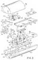
- Figure 5 is an exploded perspective view of the distal end of the endoscopic stapler of Figure 4;
- Figure 6 is a sectional perspective view of the tension bar, the distal end of which is shown in Figure 5;
- Figure 7 is a perspective view of the extensible jaws of Figure 5 having the right jaw drawn in phantom and showing the undersides thereof;
- Figure 8 is an enlarged sectional perspective view of the lower half of the distal end of the elongate tube of the endoscopic stapler of the present invention showing the extensible jaws partially extended as during the insertion of a staple and showing a nested series of staples disposed therein;
- Figure 9 is a top plan view of the lower half of the distal end portion of Figure 8 showing the extensible jaws disposed in their retracted position;
- Figure 10 is a cross sectional side view of the distal end portion of Figure 9, additionally showing the upper half thereof;
- Figure 11 is a top plan view of the lower half of the distal end portion of the endoscopic stapler of Figure 8 showing the extensible jaws disposed in their extended position;
- Figure 12 is a cross sectional side view of the endoscopic stapler of Figure 11, additionally showing the upper half thereof, with the extensible jaws disposed in their extended position; and
- Figure 13 is an enlarged top plan view of the lower half of the distal end of the endoscopic stapler of Figure 11 illustrating the crimping action thereof, an uncrimped staple being shown in phantom lines and a crimped staple being shown in solid lines.
- The detailed description set forth below in connection with the appended drawings is intended as a description of the presently preferred embodiment of the invention, and is not intended to represent the only form in which the present invention may be constructed or utilized. The description sets forth the functions and sequence of steps for constructing and operating the invention in connection with the illustrated embodiments. It is to be understood, however, that the same or equivalent functions and sequences may be accomplished by different embodiments of the invention.
- The present invention may be used in any type of endoscopic or other surgical procedure wherein it is desired to staple anatomical body portions and/or therapeutic devices in place through a relatively small opening. Because the present invention is particularly applicable to intra-abdominal laparoscopic surgical procedures, the invention will be described herein with particular reference thereto. The making of such particular reference to laparoscopic surgical procedures shall not, however, constitute a limitation on the overall description and intended application of the present invention. In fact, in addition to intra-abdominal laparoscopic procedures, the present invention may be usable in many other types of procedures.
- The improved surgical staple of the present invention is illustrated in Figures, 4, 5, and 8 - 13. The endoscopic stapler of the present invention is illustrated in Figures 1 through 13.
- Referring now to Figures 4 - 13 the improved staple of the present invention comprises a straight elongate base or
rear portion 106 andproximal bends 108 attaching first 112 and second 114 arms to thebase 106. Anabutment bend 102 is formed upon eacharm arm distal bend 110 is also formed in eacharm tips 104 bend toward each other. Thestaple 100 is preferably fabricated of stainless steel although those skilled in the art will recognize that other biologically compatible materials having similar characteristics are likewise suitable. - The
improved staple 100 of the present invention provides a staple which may be used in an endoscopic stapler and which is substantially less subject to being inadvertently pulled out than prior art staples. - The
staple 100 is sized to be received within an endoscopic stapler. The base 106 generally has a length of less than 1 cm, with a length of 4 to 6 mm being preferred. - Abutment bends 102 are provided to prevent
subsequent staples 100 from "riding up" on precedingstaples 100 as they are urged forward in a nested series (as best shown in Figures 8, 9, and 11). Without the abutment bendsubsequent staples 100 may tend to urge thearms staples 100 together, i.e. as when they are crimped, as thestaples 100 are urged toward the distal end of the endoscopic stapler, thereby distorting the shape of the precedingstaples 100 and potentially jamming the endoscopic stapler. Theabutment bend 102 maintains the positioning of thetips 104 ofsubsequent staples 100 proximate thebases 106 of precedingstaples 100 such that thearms subsequent staples 100 do not tend to ride up along thearms staples 100. Thus, performance and reliability of theimproved staple 100 is enhanced. - The abutment bends 102 also prevent the
staples 100 from inadvertently slipping out of thejaws staples 100 which would otherwise be difficult to grasp from the sides. As can be seen in Figure 8, the abutment bends 102 contact thejaws - The
distal bend 110 formed in eacharm tips 104 to curve toward each other such that crimping of thearms tips 104 closer together. Thus, crimping theimproved staple 100 of the present invention firmly secures the staple 100 in place such that the probability of the staple 100 being inadvertently pulled out of the anatomical body portion or therapeutic device into which it is inserted is substantially reduced. - The distal ends, that is, the
tips 104 of eacharm beveled surface 104A. These surfaces improve the capabilities of the staple 100 to penetrate tissue. Furthermore, the coming together of thetips 104 closer at their outside edges than on their inside edges (see Figure 13) reduces further the probability of inadvertent extraction, displacement or detachment of the crimped staples from the stapled tissue. - As the
staples 100 are crimped into place they tend to draw the two sides of a wound together, thus closing the wound in a desirable manner. Additionally, crimping causes thestaple 100 to pull layered structures together. For example, when a fabric mesh is being stapled 100 to an anatomical body portion, stapling causes thestaple 100 to pull the fabric mesh into tighter contact with the anatomical body portion as thestaple 100 is crimped. Thus, not only does the improvedsurgical staple 100 of the present invention reduce the probability of the staple 100 being inadvertently pulled out, but also tends to close wounds and improve the contact of therapeutic devices with anatomical body portions in a desirable manner. - Referring now to Figure 1, the endoscopic stapler for dispensing the
improved staples 100 of the present invention is comprised generally of an elongatetubular section 18, sized to be inserted through atrocar 12 into abody 14; and ahandle 20 having atrigger 22 pivotally attached thereto, for effecting actuation of the stapler mechanism. Thehandle 20 is further comprised of first 24 and second 26 body halves. - Referring now to Figure 2, the
distal portion 81 of thetubular member 18 of theendoscopic stapler 10 is illustrated in the process of inserting and crimping staples into awound 79 of ananatomical body portion 16. - As can be seen, a series or array of
staples 100 are inserted such that they close thewound 79 and hold the two sides of thewound 79 in position for healing. As mentioned above, the crimping process tends to draw the sides of thewound 79 together such that desirable contact is maintained and healing is facilitated. - Referring now to Figure 3, the actuation mechanism disposed within the
handle 20 is shown. The actuation mechanism comprises those components which facilitate control of the stapling process, i.e. the trigger and linkage mechanisms. Thetrigger 22 has afinger stop 30 to improve the grip thereof and thus provide better control. Thetrigger 22 pivots abouttrigger pivot post 46 such that pulling thetrigger 22 causesintegral trigger arm 48 to move forward against the biasing ofreturn spring 32.Return spring 32 is attached to thetrigger arm 48 at aperture 52 and is attached to the secondhandle body half 26 by thespring post 34. Thereturn spring 32 thus urges thetrigger 22 into an extended or non-actuated position. - A push
rod attachment block 42 has apost 44 formed thereon which extends through aslot 50 formed in thetrigger arm 48 such that forward motion of thetrigger arm 48 causes similar forward motion of the pushrod attachment block 42. Theslot 50 permits the pushrod attachment block 42 to remain in substantially the same horizontal plane as it travels forward. Fasteners or screws 40 attach the pushrod attachment block 42 to apush rod 38 which extends substantially the length of thetubular member 18. - A
trigger stop screw 36 extends from the forward portion of the handle such that it limits the rearward travel of thetrigger 22. Ascrewdriver slot 54 formed in the rearmost portion of the trigger stop screw 36 permits adjustment thereof throughaperture 56 formed in thehandle 20. - The
tubular member 18 is comprised of upper 58, and lower 60 housings. Fasteners or screws 28 attach the first 24 and second 26 handle body halves together. - Referring now to Figure 4, an enlarged view of the
distal portion 81 of thetubular member 18 is shown. Right 62 and left 64 jaws extend from anopening 66 formed in the lowertubular member housing 60 and hold animproved staple 100 of the present invention such that it may be inserted and crimped into place. Alap 85 extends downward from theupper housing 58. The abutment bends 102 formed in the staple 100 prevent it from sliding forward, out of thejaws distal portion 81 of thetubular member 18 is shown.Upper 58 and lower 60 housings contain and support the mechanisms for feeding, inserting and crimping the improvedsurgical staples 100. Theupper housing 58 has anend wall 68 formed at the distal most portion thereof. Thelower housing 60 has anopening 66 formed in the distal end thereof and continuous with achannel 43 formed therethrough and also has anupper surface 51. Ajaw closing cam 27 extends upward from the lower surface 41 of thechannel 43 proximate theopening 66. Push rod arm recesses 35 havingrear surfaces 37 and forward surfaces 39 are formed in thelower housing 60. Atrack 45 having alower surface 49 is formed substantially alongchannel 43. - A
jaw carrier 31 is formed upon thedistal portion 98 of thepush rod 38 such that thejaw carrier 31 extends toward theopening 66 of thelower housing 60 as thepush rod 38 moves forward when thetrigger 22 is actuated or depressed. Thejaw carrier 31 comprises a jawclosing cam slot 29 formed in the distal most end thereof,pivot post apertures 25 formed on either side of the jawclosing cam slot 29, and ajaw recess 23 disposed proximate thepivot post apertures 25 and configured to receive a portion of thejaws opening cam recess 21 is configured to receive ajaw opening cam 94 which is spring biased forward bycoil spring 96.Cam spring recess 19 is disposed proximal the jawopening cam recess 21 and receives thecoil spring 96. Right 11 and left 13 push rod arms extend upward from the sides of thejaw carrier 31 and havecamming surfaces 15 andupper surfaces 17 formed upon the forward upper portions thereof. Bothpush rod arms rear surface 37 of the pushrod arm recess 35 when thepush rod 38 is disposed in its rearmost position as when thetrigger 22 is not depressed or actuated. - With particular reference to Figures 5 and 7, the
jaws outboard surfaces 88, opening camming surfaces 92 (better shown in Figures 11 and 13), astaple platform 80,staple support grooves 84, closure camming surfaces 90 and pivot post apertures formed thereon. Jaw pivot posts 82 are received by the jawpivot post apertures 86 and the jaw carrierpivot post apertures 25 such that thejaws jaw carrier 31. - The spring biased
jaw opening cam 94 has anabutment surface 77 configured to abut the openingcamming surface 92 of thejaws jaws channel 43 in thelower housing 60 when thejaw carrier 31 is not extended. The closure camming surfaces 90 of thejaws jaw closing cam 27 such that the jaws are urged into a closed or crimped position when thejaw carrier 31 is extended as when thetrigger 22 is depressed or actuated.Staple platforms 80 is configured to receive and support animproved staple 100 of the present invention. Thestaple support grooves 84 capture a portion of thearms jaws - With particular reference to Figures 5, 8, 9 and 11 a
staple tray 72 is sized to be disposed within thetrack 45 in thelower housing 60 and has achannel 78 which is sized and configured to receive a series of nested improvedsurgical staples 100 of the present invention such that thestaples 100 may be fed tojaws staples 100 and maintain their positions as they are fed toward thejaws - A
staple pressure plate 55 has camming surfaces 63 configured to contact the camming surfaces 15 of thepush rod arms staple pressure plate 55 will be cammed upward when thepush rod 38 is disposed in its forward most position as when thetrigger 22 is depressed or actuated. Arecess 59 formed in thestaple pressure plate 55 receives acoil spring 57 which biases thestaple pressure plate 55 downward. - With particular reference to Figures 5 and 6, a
tension bar 70 has aforward surface 69 and is configured to be received by thestaple tray channel 78 such that when thetension bar 70 travels forward a series of nestedstaples 100 disposed therein are urged forward by theforward surface 69. - A rod 71 (shown in Figure 6) is attached to the rear portion of the
tension bar 70. Anattachment aperture 75 provides access to a fastener or screw (not shown) disposed therein for attaching therod 71 to thetension bar 70. Acoil spring 73 disposed about therod 71 urges thetension bar 70 forward such that it will cause a series of nestedstaples 100 to move forward toward thejaws - The
rod 71 extends through the rear of thehandle 20 such that the proximal end (not shown) thereof may be grasped and retracted against the urging ofcoil spring 73 such thatstaples 100 may be loaded through theopening 66 into thestaple tray 72 as discussed in further detail below. The proximal end of therod 71 may be knurled or have a knob formed thereon to facilitate grasping. - Having thus described the structure of the
improved staple 100 andendoscopic stapler 10 of the present invention, the operation thereof will be discussed in detail with reference to Figures 8 through 13 below. - With particular reference to Figures 8, 11 and 12 the lower half of the
distal portion 81 of thetubular member 18 is shown having the jaws partially extended and showing a series of nestedstaples 100 disposed within thestaple tray 72 such that they may be fed forward or digitally toward theextensible jaws staple 100 is shown disposed within thejaws jaw carrier 31 has moved sufficiently forward for theclosure camming surface 90 of thejaws jaw closing cam 27 such that further forward motion will cause thejaw closing cam 27 to cam into a closed or crimping position. - When the
distal end 81 of thetubular member 18 is placed in contact with the anatomical body portion or therapeutic device to be stapled and thetrigger 22 is partially depressed or actuated, thestaple 100 is forced into the anatomical body portion or therapeutic device as thejaws trigger 22 causes the jaws to move further forward such that thejaw closing cam 27 cams against theclosure camming surface 90 of thejaws staple 100. - In Figure 8 a nested series of improved
surgical staples 100 of the present invention are shown (in phantom) disposed within thestaple tray 72. Thestaples 100 are nested since a portion of a previous (forward) staple is disposed within or between the arms of a subsequent (rear)staple 100. - With particular reference to Figures 9 and 10, the
distal end 81 of thetubular member 18 is shown with theextensible jaws channel 43 as they would be prior to depressing or actuating thetrigger 22. In this configuration, thetips 104 of the forward most staple 100 disposed within thestaple tray 72 abut thestaple abutment surface 83 of thestaple pressure plate 55 such that further forward movement of the series of nestedstaples 100 under the urging of the tension bar 70 (shown in Figures 5 and 6) does not occur. - Depression or actuation of the
trigger 22 will cause thepush rod 38 to move forward thus causing the staple 100 disposed within thejaws opening 66 formed in the lower tubular member housing. - The spring biased jaw opening cam 94 (best shown in Figure 5) is biased towards and contacts the opening camming surfaces 92 of the
jaws jaw opening cam 94 would maintain the opened or spread apart positioning of thejaw staple 100 were presently disposed therein. This assures that theextendible jaws staple tray 72 after the staple 100 presently disposed within theextensible jaws - The camming surfaces 15 of the
arms camming surface 63 of the staple pressure plate 55 (as best shown in Figure 10). Thus, thestaple pressure plate 55 is free to travel downward under the urging ofspring 57 such that it contacts the upper surface ofstaple 100 disposed within theextensible jaws - With particular reference to Figures 11 and 12, the
distal end 81 of thetubular member 18 is shown with theextensible jaws channel 43 as they would be after partially depressing or actuating thetrigger 22. In this configuration thestaple pressure plate 55 has been cammed upward by thepush rod arms staples 100 disposed within thestaple tray 72 can move distally under the urging ofspring 73 until the distalmost staple 100 abutslip 85. Thus, the distal most staple 100 from thestaple tray 72 may be urged downward into theextensible jaws jaws - The closing camming surfaces 90 of the
extensible jaws jaw closing cam 27 in Figures 11 and 12. Further depression or actuation of thetrigger 22 would thus cause closing or crimping of the extensible jaws wherein thetips 104 of the staple 100 would be forced toward each other as theextensible jaws - With particular reference to Figures 13, the crimping action of the
jaws jaw carrier 31 forward of the position illustrated in Figures 8, 11 and 12 causes theclosure camming surface 90 of thejaws jaw closing cam 27 such that thetips 104 of a staple 100 disposed within thejaws solid lines 100. - The camming action causes the
jaws jaw opening cam 94, thereby forcing thejaw opening cam 94 backwards slightly against the urging ofspring 96. Thejaw opening cam 94 will urge thejaws tubular member 18 as thetrigger 22 is released. - The amount of crimping action applied to the
staple 100 by thejaws trigger 22 and thereby likewise limits the forward travel of thepush rod 38. Thetrigger stop screw 36 can be adjusted by placing the blade of a flat tip screwdriver within theslot 54 formed therein and rotating.Aperture 56 is provided in the rear of thehandle 20 to provide access to theslot 54 of thetrigger stop screw 36. Thus, adjustment of thetrigger stop screw 36 determines the amount whichjaws jaw closing cam 27. - With the
jaws camming surface 15 of thearms stapler pressure plate 55, thus urging thestaple pressure plate 55 upward. Releasing thetrigger 22 causes theextensible jaws tubular member 18 to the position shown in Figures 9 and 10 such that the forward most staple disposed within thestaple tray 72 may be loaded into thejaws jaw carrier 31 causes the camming surfaces 15 of thearms camming surface 63 of thestaple pressure plate 55 such that thestaple plate 55 is permitted to be urged downward bycoil spring 57. - With the
jaws staple tray 72 is free to travel forward such it will be positioned to be received by thejaws trigger 22 is released and thejaws jaws pressure plate 55 is permitted to urge the forward most staple into position such that it is received by thejaws - The endoscopic stapler of the present invention may be fabricated primarily of plastic and pre-loaded with staples at the time of manufacture such that it can be sold as a disposable item. Thus, there would be no need to refill the endoscopic stapler with staples. Alternatively, the endoscopic stapler could be fabricated of a more durable material, i.e. stainless steel, and disassembled, autoclaved, re-loaded with staples, and reassembled as required. Additionally, other forms of loading the endoscopic stapler are contemplated.
- It is understood that the exemplary improved surgical staple and the endoscopic stapler described herein and shown in the drawings represents only presently preferred embodiments of the invention.
- Modifications and additions may be made to such embodiments while remaining within the scope of the claims which follow. For example, the improved surgical staple need not be configured precisely as shown, but rather may utilize a variety of shapes that permit crimping and facilitate use with an endoscopic stapler. Thus, these and other modifications and additions may be obvious to those skilled in the art and may be implemented to adapt the present invention for use in a variety of different applications.
- Also, a variety of mechanisms are contemplated for effecting movement of the
push rod 38. Thus the present invention need not be limited to the trigger and linkage mechanisms depicted.
Claims (21)
- A surgical staple comprising:(a) a base portion (106);(b) two arms (112, 114) extending from said base portion, each arm having a distal end (104) having a bevelled surface (104a);(c) a first bend (110) formed in each arm such that the distal ends of said arms are curved inwardly toward each other and move toward each other, when the staple is crimped:
characterised in that(d) the bevelled surfaces are inwardly directed, such as to come into confronting relation when the staple is crimped thereby to reduce the probability of inadvertent extraction of the staple. - A staple as claimed in claim 1 further comprising:(a) an abutment bend (102) formed in each of said arms intermediate said first bend and said base portion; and(b) wherein a plurality of said staples are disposable in a nested series fashion within an endoscopic stapler, with the distal ends of each staple abutting respective abutment bends (102) of an adjacent staple in the series.
- A staple as claimed in claim 2 wherein:(a) said base portion is substantially straight; and(b) said abutment comprises a second bend formed in said arms.
- A staple as claimed in claim 1, 2 or 3 and made from a length of metal wire.
- An endoscopic stapler for in vivo stapling of anatomical body portions and therapeutic devices, said stapler including at least one staple as claimed in claim 1, and comprising:(a) an elongate member (18) having a distal end; said elongate member sized to be received by a trocar (12);(b) said elongate member being adapted to accommodate a plurality of staples (100);(c) an actuating mechanism (22) disposed proximate the distal end of said elongate member;(d) jaw means (62, 64) positioned at the distal ends of said elongate member, said jaw means being adapted to receive a staple from within said elongate member;wherein actuation of said actuating mechanism causes said staple to be dispensed from the distal end of said elongate member and then to be formed by said jaw means such that:(i) said staple is urged into the anatomical body portion of therapeutic device being stapled;(ii) the distal ends (104) of said staple are crimped toward each other;and wherein
the jaw means crimps said staple into a crimped position in which the distal ends of the staple face (104A) each other in a confronting relation. - A stapler as claimed in claim 5 wherein said jaw means further comprises:(a) two opposing jaws (62, 64) configured to hold and crimp a staple (100);(b) a channel (78), sized and configured to receive a series of nested staples and to feed said staples toward said jaws;(c) wherein said jaws crimp a staple held therein and said channel (76) feeds the staples received thereby in response to the actuation of said actuating mechanism.
- A stapler as claimed in claim 6 wherein said actuating mechanism comprises:(a) a trigger (23); and(b) a push rod (38) attached to said trigger such that said push rod moves in response to actuation of said trigger, said push rod being attached to said jaws such that said jaws extend in response to motion of said push rod.
- A stapler as claimed in claim 7 further comprising a pressure plate (55) disposed within the distal end of said elongate member, said pressure plate being spring biased to urge staples into said jaws.
- A stapler as claimed in claim 8 further comprising:(a) a first camming surface (15) formed on said push rod (38);(b) a second corresponding camming surface (63) formed on said pressure plate;(c) wherein the motion of said push rod resulting from the actuation of said trigger causes said first and second camming surfaces to co-operate such that said pressure plate is urged away from said jaws to facilitate the feeding of a staple from said channel to said jaws.
- A stapler as claimed in claim 9 further comprising:(a) a spring (96) disposed proximate said jaws for biasing said jaws apart;(b) a third camming surface (27) formed within said elongate member;(c) fourth camming surfaces (90) formed upon said jaws;(d) wherein extension of said jaws causes said third and fourth camming surfaces to co-operate to urge said jaws together.
- A stapler as claimed in claim 7, 8, 9 or 10 and further comprising an adjustment means (54) disposed within said stapler for limiting the movement of said trigger such that the amount of crimp applied to a staple may be selectively varied.
- A stapler as claimed in any one of claims 6 to 11 and further comprising a spring (73) for urging a series of nested staples through said channel toward said jaws.
- A stapler as claimed in any one of claims 5 to 12 wherein the outer diameter of said elongate member (18) is less than one centimeter.
- An endoscopic stapling system for in vivo stapling anatomical body portions and therapeutic devices, said stapling system comprising:(a) a staple (100) as claimed in claim 1;(b) a stapler having jaw means (62, 64) configured to sequentially receive a plurality of said staples, and to crimp said staples to anatomical portions of the body and to therapeutic devices.
- A stapling system as claimed in claim 14 wherein:(a) said stapler comprises:(i) an elongate member (18) having a distal end, said elongate member sized to be received by a trocar (12), a plurality of said staples (100) being disposable within said elongate member;(ii) an actuating mechanism (22) disposed proximate the proximal end of said elongate member; and(b) wherein actuation of said actuating mechanism causes a staple to be disposed from the distal end of said elongate member such that(i) said staple is urged into the material being stapled;(ii) the distal ends (104) of said staple are crimped toward each other, to bring them into said confronting relation.
- A stapling system as claimed in claim 14 or 15 wherein:(a) said staple further comprises an abutment bend (102) formed in said arms intermediate said first bend and said base portion;(b) said stapler further comprises:(i) two opposing jaws (62, 64) configured to hold and crimp a staple; and(ii) a channel (78), sized and configured to receive a series of nested staples and to feed said staples toward said jaws; and(c) wherein:(i) said jaws are able to crimp a staple held therein;(ii) said abutment bend (102) prevents said staple from slipping from said jaws prior to being crimped; and(iii) said channel feeds staples received thereby to said jaws in response to the actuation of said actuating mechanism.
- A stapling system as claimed in claim 16 wherein:(a) said base portion (106) is substantially straight;(b) said abutment bend (102) comprises a second bend in said arms; and(c) said actuating mechanism comprises:(i) a trigger (22); and(ii) a push rod (38) attached to said trigger such that said push rod moves in response to actuation of said trigger, said push rod being attached to said jaws such that said jaws extend in response to motion of said push rod.
- A stapling system as claimed in any one of claims 14 to 17 wherein:(a) said stapler further comprises a pressure plate (55) disposed within the distal end of said elongate member and spring-biased (73) to urge staples into said jaws.
- A stapling system as claimed in claim 18 wherein:(a) at least one first camming surface (15) is formed on said push rod (38);(b) at least one second corresponding camming surface (63) is formed on said pressure plate (55);(c) wherein the motion of said push rod resulting from the actuation of said trigger causes said first and second camming surfaces to co-operate such that said pressure plate is urged away from said jaws to facilitate the feeding of a staple from said channel to said jaws.
- A stapling system as claimed in claim 19 further comprising:(a) a spring (96) disposed proximate said jaws for biasing said jaws apart;(b) a third camming surface (27) formed within said elongate member;(c) fourth camming surfaces (90) formed upon said jaws:(d) wherein extension of said jaws causes said third and fourth camming surfaces to co-operate to urge said jaws together.
- A stapling system as claimed in claim 17, or any one of claims 18 to 20 as dependent on claim 17, further comprising:(a) an adjustment means (54) disposed within said stapler for limiting the movement of said trigger such that the amount of crimp applied to a staple may be varied;(b) a spring (73) for urging said series of nested staples through said channel toward said jaws; and(c) wherein the outer diameter of said elongate member (18) is less than one centimeter.
Applications Claiming Priority (2)
| Application Number | Priority Date | Filing Date | Title |
|---|---|---|---|
| US65302991A | 1991-02-08 | 1991-02-08 | |
| US653029 | 1991-02-08 |
Publications (3)
| Publication Number | Publication Date |
|---|---|
| EP0503271A2 EP0503271A2 (en) | 1992-09-16 |
| EP0503271A3 EP0503271A3 (en) | 1992-10-28 |
| EP0503271B1true EP0503271B1 (en) | 1997-05-21 |
Family
ID=24619205
Family Applications (1)
| Application Number | Title | Priority Date | Filing Date |
|---|---|---|---|
| EP92101970AExpired - LifetimeEP0503271B1 (en) | 1991-02-08 | 1992-02-06 | Surgical staple and endoscopic stapler |
Country Status (4)
| Country | Link |
|---|---|
| US (1) | US5392978A (en) |
| EP (1) | EP0503271B1 (en) |
| CA (1) | CA2060040A1 (en) |
| DE (1) | DE69219806T2 (en) |
Families Citing this family (159)
| Publication number | Priority date | Publication date | Assignee | Title |
|---|---|---|---|---|
| US5171249A (en)* | 1991-04-04 | 1992-12-15 | Ethicon, Inc. | Endoscopic multiple ligating clip applier |
| FR2702647B1 (en)* | 1993-03-18 | 1995-05-05 | Baudet Jacques | Process of micro-anastomosis of blood vessels and automatic clamp for its implementation. |
| US5562682A (en)* | 1993-10-08 | 1996-10-08 | Richard-Allan Medical Industries, Inc. | Surgical Instrument with adjustable arms |
| US5715987A (en)* | 1994-04-05 | 1998-02-10 | Tracor Incorporated | Constant width, adjustable grip, staple apparatus and method |
| US5695524A (en)* | 1994-04-05 | 1997-12-09 | Tracor Aerospace, Inc. | Constant width, adjustable grip, staple apparatus and method |
| US6132438A (en) | 1995-06-07 | 2000-10-17 | Ep Technologies, Inc. | Devices for installing stasis reducing means in body tissue |
| US20110077672A1 (en)* | 1995-06-07 | 2011-03-31 | Fleischman Sidney D | Devices For Installing Stasis Reducing Means In Body Tissue |
| US5730758A (en)* | 1996-09-12 | 1998-03-24 | Allgeyer; Dean O. | Staple and staple applicator for use in skin fixation of catheters |
| US6027815A (en)* | 1996-11-06 | 2000-02-22 | Taiwan Semiconductor Manufacturing Company | Non-absorbing anti-reflective coated (ARC) reticle using thin dielectric films and method of forming reticle |
| US5910141A (en) | 1997-02-12 | 1999-06-08 | Sdgi Holdings, Inc. | Rod introduction apparatus |
| US5941890A (en)* | 1998-06-26 | 1999-08-24 | Ethicon Endo-Surgery, Inc. | Implantable surgical marker |
| US6228098B1 (en)* | 1998-07-10 | 2001-05-08 | General Surgical Innovations, Inc. | Apparatus and method for surgical fastening |
| US6059787A (en)* | 1999-04-26 | 2000-05-09 | Allen; Drew | Compression bone staple apparatus and method |
| US7695485B2 (en) | 2001-11-30 | 2010-04-13 | Power Medical Interventions, Llc | Surgical device |
| US6461364B1 (en)* | 2000-01-05 | 2002-10-08 | Integrated Vascular Systems, Inc. | Vascular sheath with bioabsorbable puncture site closure apparatus and methods of use |
| US6391048B1 (en)* | 2000-01-05 | 2002-05-21 | Integrated Vascular Systems, Inc. | Integrated vascular device with puncture site closure component and sealant and methods of use |
| US7842068B2 (en)* | 2000-12-07 | 2010-11-30 | Integrated Vascular Systems, Inc. | Apparatus and methods for providing tactile feedback while delivering a closure device |
| US6942674B2 (en) | 2000-01-05 | 2005-09-13 | Integrated Vascular Systems, Inc. | Apparatus and methods for delivering a closure device |
| US6197042B1 (en)* | 2000-01-05 | 2001-03-06 | Medical Technology Group, Inc. | Vascular sheath with puncture site closure apparatus and methods of use |
| US8758400B2 (en) | 2000-01-05 | 2014-06-24 | Integrated Vascular Systems, Inc. | Closure system and methods of use |
| US9579091B2 (en)* | 2000-01-05 | 2017-02-28 | Integrated Vascular Systems, Inc. | Closure system and methods of use |
| KR20020081295A (en)* | 2000-02-04 | 2002-10-26 | 이매진 메디칼 테크놀로지즈 캘리포니아, 인코포레이티드. | Surgical clip applier |
| US6533157B1 (en)* | 2000-02-22 | 2003-03-18 | Power Medical Interventions, Inc. | Tissue stapling attachment for use with an electromechanical driver device |
| US8016855B2 (en)* | 2002-01-08 | 2011-09-13 | Tyco Healthcare Group Lp | Surgical device |
| AU2001288462A1 (en) | 2000-08-30 | 2002-03-13 | Cerebral Vascular Applications Inc. | Medical instrument |
| US6755842B2 (en)* | 2000-09-01 | 2004-06-29 | Angiolink Corporation | Advanced wound site management systems and methods |
| US20040093024A1 (en)* | 2000-09-01 | 2004-05-13 | James Lousararian | Advanced wound site management systems and methods |
| US6767356B2 (en)* | 2000-09-01 | 2004-07-27 | Angiolink Corporation | Advanced wound site management systems and methods |
| DE60144328D1 (en)* | 2000-09-08 | 2011-05-12 | Abbott Vascular Inc | Surgical clamp |
| US6626918B1 (en) | 2000-10-06 | 2003-09-30 | Medical Technology Group | Apparatus and methods for positioning a vascular sheath |
| US6623510B2 (en) | 2000-12-07 | 2003-09-23 | Integrated Vascular Systems, Inc. | Closure device and methods for making and using them |
| US7905900B2 (en) | 2003-01-30 | 2011-03-15 | Integrated Vascular Systems, Inc. | Clip applier and methods of use |
| US8690910B2 (en) | 2000-12-07 | 2014-04-08 | Integrated Vascular Systems, Inc. | Closure device and methods for making and using them |
| US7211101B2 (en) | 2000-12-07 | 2007-05-01 | Abbott Vascular Devices | Methods for manufacturing a clip and clip |
| US6695867B2 (en) | 2002-02-21 | 2004-02-24 | Integrated Vascular Systems, Inc. | Plunger apparatus and methods for delivering a closure device |
| US7806904B2 (en)* | 2000-12-07 | 2010-10-05 | Integrated Vascular Systems, Inc. | Closure device |
| US6835199B2 (en) | 2001-01-31 | 2004-12-28 | Rex Medical, L.P. | Apparatus and method for resectioning gastro-esophageal tissue |
| US7048748B1 (en) | 2001-03-21 | 2006-05-23 | Uestuener Emin Tuncay | Automatic surgical suturing instrument and method |
| IES20010547A2 (en)* | 2001-06-07 | 2002-12-11 | Christy Cummins | Surgical Staple |
| US6440133B1 (en) | 2001-07-03 | 2002-08-27 | Sdgi Holdings, Inc. | Rod reducer instruments and methods |
| US6755338B2 (en)* | 2001-08-29 | 2004-06-29 | Cerebral Vascular Applications, Inc. | Medical instrument |
| US8231639B2 (en)* | 2001-11-28 | 2012-07-31 | Aptus Endosystems, Inc. | Systems and methods for attaching a prosthesis within a body lumen or hollow organ |
| US9113878B2 (en) | 2002-01-08 | 2015-08-25 | Covidien Lp | Pinion clip for right angle linear cutter |
| IES20030424A2 (en)* | 2002-06-04 | 2003-12-10 | Robert Stevenson | Blood vessel closure clip and delivery device |
| US7108710B2 (en) | 2002-11-26 | 2006-09-19 | Abbott Laboratories | Multi-element biased suture clip |
| US6915804B2 (en)* | 2002-12-03 | 2005-07-12 | University Of Florida | Tracheotomy surgical device |
| US7399310B2 (en)* | 2002-12-16 | 2008-07-15 | Edrich Vascular Devices, Inc. | Endovascular stapler |
| US8627992B2 (en)* | 2002-12-16 | 2014-01-14 | Edrich Health Technologies, Inc. | Endovascular stapler |
| US7343920B2 (en)* | 2002-12-20 | 2008-03-18 | Toby E Bruce | Connective tissue repair system |
| US8821534B2 (en) | 2010-12-06 | 2014-09-02 | Integrated Vascular Systems, Inc. | Clip applier having improved hemostasis and methods of use |
| US7857828B2 (en)* | 2003-01-30 | 2010-12-28 | Integrated Vascular Systems, Inc. | Clip applier and methods of use |
| US8905937B2 (en)* | 2009-02-26 | 2014-12-09 | Integrated Vascular Systems, Inc. | Methods and apparatus for locating a surface of a body lumen |
| US8202293B2 (en) | 2003-01-30 | 2012-06-19 | Integrated Vascular Systems, Inc. | Clip applier and methods of use |
| US8398656B2 (en) | 2003-01-30 | 2013-03-19 | Integrated Vascular Systems, Inc. | Clip applier and methods of use |
| US8758398B2 (en)* | 2006-09-08 | 2014-06-24 | Integrated Vascular Systems, Inc. | Apparatus and method for delivering a closure element |
| US7175648B2 (en)* | 2003-11-18 | 2007-02-13 | Granit Medical Innovations, Llc | Deep endoscopic staple and stapler |
| EP1744796B1 (en) | 2004-04-20 | 2015-03-18 | Genzyme Corporation | Surgical mesh-like implant |
| WO2005115254A2 (en)* | 2004-05-17 | 2005-12-08 | Datascope Investment Corp. | Surgical stapling system |
| IES20040368A2 (en)* | 2004-05-25 | 2005-11-30 | James E Coleman | Surgical stapler |
| US8926633B2 (en)* | 2005-06-24 | 2015-01-06 | Abbott Laboratories | Apparatus and method for delivering a closure element |
| US20080312686A1 (en)* | 2005-07-01 | 2008-12-18 | Abbott Laboratories | Antimicrobial closure element and closure element applier |
| US8313497B2 (en)* | 2005-07-01 | 2012-11-20 | Abbott Laboratories | Clip applier and methods of use |
| US20070060895A1 (en) | 2005-08-24 | 2007-03-15 | Sibbitt Wilmer L Jr | Vascular closure methods and apparatuses |
| US9456811B2 (en)* | 2005-08-24 | 2016-10-04 | Abbott Vascular Inc. | Vascular closure methods and apparatuses |
| US8920442B2 (en) | 2005-08-24 | 2014-12-30 | Abbott Vascular Inc. | Vascular opening edge eversion methods and apparatuses |
| US7845537B2 (en)* | 2006-01-31 | 2010-12-07 | Ethicon Endo-Surgery, Inc. | Surgical instrument having recording capabilities |
| US8808310B2 (en)* | 2006-04-20 | 2014-08-19 | Integrated Vascular Systems, Inc. | Resettable clip applier and reset tools |
| US8021389B2 (en)* | 2006-05-17 | 2011-09-20 | Warsaw Orthopedic, Inc. | Surgical staple assembly |
| DE202006008409U1 (en)* | 2006-05-27 | 2006-08-10 | Eugster/Frismag Ag | Dissolving unit for instant powder, especially powdered milk, comprises a flow inducing member, a foam chamber and a nozzle |
| USD611144S1 (en) | 2006-06-28 | 2010-03-02 | Abbott Laboratories | Apparatus for delivering a closure element |
| US8556930B2 (en) | 2006-06-28 | 2013-10-15 | Abbott Laboratories | Vessel closure device |
| US7434716B2 (en)* | 2006-12-21 | 2008-10-14 | Tyco Healthcare Group Lp | Staple driver for articulating surgical stapler |
| US20080173691A1 (en)* | 2007-01-24 | 2008-07-24 | Medtronic Vascular, Inc. | Low-Profile Vascular Closure Systems and Methods of Using Same |
| US20080262524A1 (en)* | 2007-04-19 | 2008-10-23 | Searete Llc, A Limited Liability Corporation Of The State Of Delaware | Systems and methods for closing of fascia |
| US20080262390A1 (en)* | 2007-04-19 | 2008-10-23 | Searete Llc, A Limited Liability Corporation Of The State Of Delaware | Fiducials for placement of tissue closures |
| GB2479307B (en) | 2007-04-19 | 2012-03-07 | Searete Llc | Fiducials for placement of tissue closures |
| US20080262540A1 (en)* | 2007-04-19 | 2008-10-23 | Searete Llc, A Limited Liability Corporation Of The State Of Delaware | Systems and methods for approximating surfaces |
| US8226681B2 (en)* | 2007-06-25 | 2012-07-24 | Abbott Laboratories | Methods, devices, and apparatus for managing access through tissue |
| US20100082046A1 (en)* | 2007-07-18 | 2010-04-01 | Harris Jason L | Device For Deploying A Fastener For Use in a Gastric Volume Reduction Procedure |
| US8893947B2 (en)* | 2007-12-17 | 2014-11-25 | Abbott Laboratories | Clip applier and methods of use |
| US20090157101A1 (en) | 2007-12-17 | 2009-06-18 | Abbott Laboratories | Tissue closure system and methods of use |
| US7841502B2 (en)* | 2007-12-18 | 2010-11-30 | Abbott Laboratories | Modular clip applier |
| US20090187215A1 (en)* | 2007-12-19 | 2009-07-23 | Abbott Laboratories | Methods and apparatus to reduce a dimension of an implantable device in a smaller state |
| US8758373B2 (en) | 2008-02-18 | 2014-06-24 | Covidien Lp | Means and method for reversibly connecting a patch to a patch deployment device |
| US8317808B2 (en) | 2008-02-18 | 2012-11-27 | Covidien Lp | Device and method for rolling and inserting a prosthetic patch into a body cavity |
| WO2009104182A2 (en) | 2008-02-18 | 2009-08-27 | Polytouch Medical Ltd | A device and method for deploying and attaching a patch to a biological tissue |
| US9044235B2 (en) | 2008-02-18 | 2015-06-02 | Covidien Lp | Magnetic clip for implant deployment device |
| US9398944B2 (en) | 2008-02-18 | 2016-07-26 | Covidien Lp | Lock bar spring and clip for implant deployment device |
| US9833240B2 (en) | 2008-02-18 | 2017-12-05 | Covidien Lp | Lock bar spring and clip for implant deployment device |
| US9034002B2 (en) | 2008-02-18 | 2015-05-19 | Covidien Lp | Lock bar spring and clip for implant deployment device |
| US8808314B2 (en)* | 2008-02-18 | 2014-08-19 | Covidien Lp | Device and method for deploying and attaching an implant to a biological tissue |
| US9393002B2 (en) | 2008-02-18 | 2016-07-19 | Covidien Lp | Clip for implant deployment device |
| US9301826B2 (en) | 2008-02-18 | 2016-04-05 | Covidien Lp | Lock bar spring and clip for implant deployment device |
| US9393093B2 (en) | 2008-02-18 | 2016-07-19 | Covidien Lp | Clip for implant deployment device |
| US20090242609A1 (en)* | 2008-03-31 | 2009-10-01 | Medtronic Vascular, Inc. | Vascular Puncture Closure Staple With Tip Protection |
| US9084599B2 (en) | 2008-05-01 | 2015-07-21 | Ethicon Endo-Surgery, Inc. | Surgical stapling instrument for applying a large staple through a small delivery port and a method of using the surgical stapler to secure a tissue fold |
| US9282965B2 (en)* | 2008-05-16 | 2016-03-15 | Abbott Laboratories | Apparatus and methods for engaging tissue |
| US8357170B2 (en)* | 2008-07-09 | 2013-01-22 | Ethicon Endo-Surgery, Inc. | Devices and methods for placing occlusion fasteners |
| EP2337502B1 (en)* | 2008-10-20 | 2014-08-06 | Covidien LP | A device for attaching a patch to a biological tissue |
| US8398676B2 (en)* | 2008-10-30 | 2013-03-19 | Abbott Vascular Inc. | Closure device |
| US8858594B2 (en) | 2008-12-22 | 2014-10-14 | Abbott Laboratories | Curved closure device |
| US8323312B2 (en)* | 2008-12-22 | 2012-12-04 | Abbott Laboratories | Closure device |
| US20100179589A1 (en) | 2009-01-09 | 2010-07-15 | Abbott Vascular Inc. | Rapidly eroding anchor |
| US9486191B2 (en) | 2009-01-09 | 2016-11-08 | Abbott Vascular, Inc. | Closure devices |
| US9089311B2 (en)* | 2009-01-09 | 2015-07-28 | Abbott Vascular Inc. | Vessel closure devices and methods |
| US9414820B2 (en)* | 2009-01-09 | 2016-08-16 | Abbott Vascular Inc. | Closure devices, systems, and methods |
| US9173644B2 (en) | 2009-01-09 | 2015-11-03 | Abbott Vascular Inc. | Closure devices, systems, and methods |
| US20100185234A1 (en)* | 2009-01-16 | 2010-07-22 | Abbott Vascular Inc. | Closure devices, systems, and methods |
| US20100191262A1 (en)* | 2009-01-26 | 2010-07-29 | Harris Jason L | Surgical stapler for applying a large staple through small delivery port and a method of using the stapler to secure a tissue fold |
| US8469252B2 (en) | 2009-01-26 | 2013-06-25 | Ethicon Endo-Surgery, Inc. | Surgical stapler fastening device with adjustable anvil |
| US8801732B2 (en)* | 2009-01-26 | 2014-08-12 | Ethicon Endo-Surgery, Inc. | Surgical stapler to secure a tissue fold |
| US20100187283A1 (en)* | 2009-01-26 | 2010-07-29 | Lawrence Crainich | Method For Feeding Staples In a Low Profile Surgical Stapler |
| US8453905B2 (en) | 2009-01-26 | 2013-06-04 | Ethicon Endo-Surgery, Inc. | Surgical fastener for applying a large staple through a small delivery port |
| US8602286B2 (en)* | 2009-01-26 | 2013-12-10 | Ethicon Endo-Surgery, Inc. | Apparatus for feeding staples in a low profile surgical stapler |
| US20100187285A1 (en)* | 2009-01-26 | 2010-07-29 | Harris Jason L | Surgical stapler for applying a large staple though a small delivery port and a method of using the stapler to secure a tissue fold |
| US9713471B2 (en) | 2009-01-26 | 2017-07-25 | Ethicon Endo-Surgery, Inc. | Surgical device with tandem fasteners |
| US9713468B2 (en)* | 2009-01-26 | 2017-07-25 | Ethicon Endo-Surgery, Inc. | Surgical stapler for applying a large staple through a small delivery port and a method of using the stapler to secure a tissue fold |
| US8439244B2 (en) | 2010-01-20 | 2013-05-14 | Ethicon Endo-Surgery, Inc. | Surgical stapler fastening device with movable anvil |
| US8056789B1 (en) | 2009-06-03 | 2011-11-15 | Cardica, Inc. | Staple and feeder belt configurations for surgical stapler |
| WO2011021082A1 (en)* | 2009-08-17 | 2011-02-24 | PolyTouch Medical, Inc. | Means and method for reversibly connecting an implant to a deployment device |
| US8906045B2 (en)* | 2009-08-17 | 2014-12-09 | Covidien Lp | Articulating patch deployment device and method of use |
| US20110054492A1 (en)* | 2009-08-26 | 2011-03-03 | Abbott Laboratories | Medical device for repairing a fistula |
| US8328061B2 (en) | 2010-02-02 | 2012-12-11 | Covidien Lp | Surgical instrument for joining tissue |
| US8303624B2 (en)* | 2010-03-15 | 2012-11-06 | Abbott Cardiovascular Systems, Inc. | Bioabsorbable plug |
| US8758399B2 (en) | 2010-08-02 | 2014-06-24 | Abbott Cardiovascular Systems, Inc. | Expandable bioabsorbable plug apparatus and method |
| US8603116B2 (en) | 2010-08-04 | 2013-12-10 | Abbott Cardiovascular Systems, Inc. | Closure device with long tines |
| US8617184B2 (en) | 2011-02-15 | 2013-12-31 | Abbott Cardiovascular Systems, Inc. | Vessel closure system |
| US9149276B2 (en) | 2011-03-21 | 2015-10-06 | Abbott Cardiovascular Systems, Inc. | Clip and deployment apparatus for tissue closure |
| US9332976B2 (en) | 2011-11-30 | 2016-05-10 | Abbott Cardiovascular Systems, Inc. | Tissue closure device |
| US8535339B2 (en)* | 2011-12-18 | 2013-09-17 | Via Surgical Ltd. | Apparatus and method for suturing |
| US8992547B2 (en) | 2012-03-21 | 2015-03-31 | Ethicon Endo-Surgery, Inc. | Methods and devices for creating tissue plications |
| US9888913B2 (en) | 2012-05-31 | 2018-02-13 | Via Surgical Ltd. | Variable depth surgical fixation |
| US9364209B2 (en) | 2012-12-21 | 2016-06-14 | Abbott Cardiovascular Systems, Inc. | Articulating suturing device |
| US20150173756A1 (en)* | 2013-12-23 | 2015-06-25 | Ethicon Endo-Surgery, Inc. | Surgical cutting and stapling methods |
| US9724092B2 (en) | 2013-12-23 | 2017-08-08 | Ethicon Llc | Modular surgical instruments |
| US9839428B2 (en) | 2013-12-23 | 2017-12-12 | Ethicon Llc | Surgical cutting and stapling instruments with independent jaw control features |
| US9655616B2 (en)* | 2014-01-22 | 2017-05-23 | Covidien Lp | Apparatus for endoscopic procedures |
| ES2821006T3 (en) | 2015-04-23 | 2021-04-23 | Via Surgical Ltd | Surgical Fastener Locking and Delivery Mechanism |
| EP3479779B1 (en) | 2015-05-20 | 2023-02-22 | Biedermann Technologies GmbH & Co. KG | Surgical staple and instrument for holding and implanting the surgical staple |
| MX2022009705A (en) | 2015-08-26 | 2022-11-07 | Ethicon Llc | Surgical staples comprising hardness variations for improved fastening of tissue. |
| RU2725081C2 (en) | 2015-08-26 | 2020-06-29 | ЭТИКОН ЭлЭлСи | Strips with surgical staples allowing the presence of staples with variable properties and providing simple loading of the cartridge |
| US10980538B2 (en) | 2015-08-26 | 2021-04-20 | Ethicon Llc | Surgical stapling configurations for curved and circular stapling instruments |
| MX2018002392A (en) | 2015-08-26 | 2018-08-01 | Ethicon Llc | Staple cartridge assembly comprising various tissue compression gaps and staple forming gaps. |
| US10238390B2 (en) | 2015-09-02 | 2019-03-26 | Ethicon Llc | Surgical staple cartridges with driver arrangements for establishing herringbone staple patterns |
| MX2022006189A (en) | 2015-09-02 | 2022-06-16 | Ethicon Llc | Surgical staple configurations with camming surfaces located between portions supporting surgical staples. |
| US10543072B2 (en)* | 2015-09-24 | 2020-01-28 | Boston Scientific Scimed, Inc. | Implant fixation devices and methods of using the same |
| USD847989S1 (en) | 2016-06-24 | 2019-05-07 | Ethicon Llc | Surgical fastener cartridge |
| USD850617S1 (en) | 2016-06-24 | 2019-06-04 | Ethicon Llc | Surgical fastener cartridge |
| JP6957532B2 (en) | 2016-06-24 | 2021-11-02 | エシコン エルエルシーEthicon LLC | Staple cartridges including wire staples and punched staples |
| US10893863B2 (en) | 2016-06-24 | 2021-01-19 | Ethicon Llc | Staple cartridge comprising offset longitudinal staple rows |
| JP6980705B2 (en) | 2016-06-24 | 2021-12-15 | エシコン エルエルシーEthicon LLC | Stapling system for use with wire staples and punched staples |
| USD826405S1 (en) | 2016-06-24 | 2018-08-21 | Ethicon Llc | Surgical fastener |
| US10945727B2 (en) | 2016-12-21 | 2021-03-16 | Ethicon Llc | Staple cartridge with deformable driver retention features |
| US10687810B2 (en) | 2016-12-21 | 2020-06-23 | Ethicon Llc | Stepped staple cartridge with tissue retention and gap setting features |
| US11684367B2 (en) | 2016-12-21 | 2023-06-27 | Cilag Gmbh International | Stepped assembly having and end-of-life indicator |
| US20180168648A1 (en) | 2016-12-21 | 2018-06-21 | Ethicon Endo-Surgery, Llc | Durability features for end effectors and firing assemblies of surgical stapling instruments |
| US10993715B2 (en) | 2016-12-21 | 2021-05-04 | Ethicon Llc | Staple cartridge comprising staples with different clamping breadths |
| US11006948B2 (en)* | 2017-06-28 | 2021-05-18 | Biedermann Technologies Gmbh & Co. Kg | Surgical staple and instrument for holding and implanting the surgical staple |
| CN117159069B (en)* | 2023-11-03 | 2024-01-02 | 德州市红拳医疗器械有限公司 | Quick operation purse-string forceps for laparoscope |
Citations (1)
| Publication number | Priority date | Publication date | Assignee | Title |
|---|---|---|---|---|
| EP0283127A1 (en)* | 1987-02-17 | 1988-09-21 | Minnesota Mining And Manufacturing Company | Surgical staple |
Family Cites Families (134)
| Publication number | Priority date | Publication date | Assignee | Title |
|---|---|---|---|---|
| US389660A (en)* | 1888-09-18 | Metallic fastener | ||
| US3124136A (en)* | 1964-03-10 | Method of repairing body tissue | ||
| US3054406A (en)* | 1958-10-17 | 1962-09-18 | Phillips Petroleum Co | Surgical mesh |
| US3120230A (en)* | 1960-10-24 | 1964-02-04 | Jack H Sanders | Surgical clamp |
| US3314431A (en)* | 1964-10-05 | 1967-04-18 | Jr Raymond M Smith | Stylet for insertion of endotracheal catheter |
| US3494533A (en)* | 1966-10-10 | 1970-02-10 | United States Surgical Corp | Surgical stapler for stitching body organs |
| US3631707A (en)* | 1969-06-13 | 1972-01-04 | Weck & Co Inc Edward | Hemostatic clip applicator |
| US3643851A (en)* | 1969-08-25 | 1972-02-22 | United States Surgical Corp | Skin stapler |
| US3837555A (en)* | 1970-12-14 | 1974-09-24 | Surgical Corp | Powering instrument for stapling skin and fascia |
| US3763860A (en)* | 1971-08-26 | 1973-10-09 | H Clarke | Laparoscopy instruments and method for suturing and ligation |
| US3871379A (en)* | 1971-08-26 | 1975-03-18 | Henry C N Clarke | Laparoscopy instruments and method for suturing and ligation |
| US3777538A (en)* | 1972-03-15 | 1973-12-11 | Weck & Co Edward | Surgical clip applicator |
| USRE28932E (en)* | 1972-09-29 | 1976-08-17 | United States Surgical Corporation | Surgical stapling instrument |
| DE2330182A1 (en) | 1973-06-14 | 1975-01-02 | Wolf Gmbh Richard | PLIERS FOR SETTING TANTALUM CLIPS |
| US3882854A (en)* | 1973-08-23 | 1975-05-13 | Research Corp | Surgical clip and applicator |
| JPS552966Y2 (en)* | 1974-02-08 | 1980-01-24 | ||
| US4027510A (en)* | 1974-05-15 | 1977-06-07 | Siegfried Hiltebrandt | Forceps |
| US3955581A (en)* | 1974-10-18 | 1976-05-11 | United States Surgical Corporation | Three-stage surgical instrument |
| GB1486351A (en)* | 1975-06-06 | 1977-09-21 | Rocket Of London Ltd | Surgical clip applicator |
| US4014492A (en)* | 1975-06-11 | 1977-03-29 | Senco Products, Inc. | Surgical staple |
| US4043504A (en)* | 1976-03-09 | 1977-08-23 | Senco Products, Inc. | Staple cartridge and feed means for use with a surgical stapling instrument |
| US4166466A (en)* | 1976-10-08 | 1979-09-04 | Jarvik Robert K | Repeating hemostatic clip applying instruments and multi-clip cartridges therefor |
| US4127227A (en)* | 1976-10-08 | 1978-11-28 | United States Surgical Corporation | Wide fascia staple cartridge |
| US4412539A (en)* | 1976-10-08 | 1983-11-01 | United States Surgical Corporation | Repeating hemostatic clip applying instruments and multi-clip cartridges therefor |
| DE2703529A1 (en) | 1977-01-28 | 1978-08-03 | Krupp Gmbh | IMPLANT TO CONNECT SEPARATION SITES IN LIVING TISSUE |
| US4207873A (en)* | 1977-05-16 | 1980-06-17 | American Cystoscope Makers, Inc. | Endoscope deflection control |
| CA1082552A (en)* | 1977-08-05 | 1980-07-29 | Charles H. Klieman | Hemostatic clip applicator |
| US4316468A (en)* | 1977-08-05 | 1982-02-23 | Charles H. Klieman | Surgical stapler |
| US4169476A (en)* | 1977-08-12 | 1979-10-02 | Wolf Medical Instruments Corporation | Applicator for surgical clip |
| US4152920A (en)* | 1977-10-17 | 1979-05-08 | United States Surgical Corporation | System for applying surgical clips |
| US4196836A (en)* | 1978-02-14 | 1980-04-08 | Senco Products Inc. | Surgical stapling instrument |
| US4321002A (en)* | 1978-03-27 | 1982-03-23 | Minnesota Mining And Manufacturing Company | Medical stapling device |
| US4256251A (en)* | 1978-04-24 | 1981-03-17 | Lawrence M. Smith | Surgical staplers and staple |
| US4204623A (en)* | 1978-07-17 | 1980-05-27 | United States Surgical Corporation | Manually powered surgical stapling instrument |
| US4246903A (en)* | 1979-04-02 | 1981-01-27 | American Cyanamid Company | Surgical instrument to apply a hemostatic clip to a vessel and method of using the same |
| US4228895A (en)* | 1979-04-02 | 1980-10-21 | American Cyanamid Company | Magazine tape containing a plurality of hemostatic clips |
| US4261244A (en)* | 1979-05-14 | 1981-04-14 | Senco Products, Inc. | Surgical staple |
| US4403693A (en)* | 1979-09-24 | 1983-09-13 | Minnesota Mining And Manufacturing Company | Medical stapling device |
| US4399810A (en)* | 1979-11-28 | 1983-08-23 | Samuels Peter B | Skin clip and applier |
| AU534210B2 (en)* | 1980-02-05 | 1984-01-12 | United States Surgical Corporation | Surgical staples |
| US4437847A (en)* | 1980-05-05 | 1984-03-20 | Koppers Company, Inc. | Flexible coupling |
| US4317535A (en)* | 1980-05-15 | 1982-03-02 | Minnesota Mining And Manufacturing Company | Stapler with tapered anvil |
| US4406392A (en)* | 1980-05-27 | 1983-09-27 | American Cyanamid Company | Surgical stapling instrument |
| US4347847A (en)* | 1980-06-06 | 1982-09-07 | Usher Francis C | Method of hernia repair |
| US4452245A (en)* | 1980-06-06 | 1984-06-05 | Usher Francis C | Surgical mesh and method |
| US4452357A (en)* | 1980-07-22 | 1984-06-05 | Charles H. Klieman | Surgical stapler |
| CA1170536A (en)* | 1980-08-25 | 1984-07-10 | United States Surgical Corporation | Surgical staples |
| US4591086A (en)* | 1980-09-26 | 1986-05-27 | American Cyanamid Company | Surgical stapling instrument |
| US4349028A (en)* | 1980-10-03 | 1982-09-14 | United States Surgical Corporation | Surgical stapling apparatus having self-contained pneumatic system for completing manually initiated motion sequence |
| AU542936B2 (en)* | 1980-10-17 | 1985-03-28 | United States Surgical Corporation | Self centering staple |
| US4375866A (en)* | 1981-01-22 | 1983-03-08 | Edward Weck & Company, Inc. | Skin clip applier |
| US4526174A (en)* | 1981-03-27 | 1985-07-02 | Minnesota Mining And Manufacturing Company | Staple and cartridge for use in a tissue stapling device and a tissue closing method |
| US4394864A (en)* | 1981-04-15 | 1983-07-26 | Jeffrey Sandhaus | Apparatus and method for effecting occlusion of the vas deferens |
| US4485816A (en)* | 1981-06-25 | 1984-12-04 | Alchemia | Shape-memory surgical staple apparatus and method for use in surgical suturing |
| US4662373A (en)* | 1981-06-29 | 1987-05-05 | American Cyanamid Company | Surgical ligating instrument |
| DE3204532C2 (en) | 1982-02-10 | 1983-12-08 | B. Braun Melsungen Ag, 3508 Melsungen | Surgical skin staple |
| DE3204522A1 (en)* | 1982-02-10 | 1983-08-25 | B. Braun Melsungen Ag, 3508 Melsungen | SURGICAL SKIN CLIP DEVICE |
| US4509518A (en)* | 1982-02-17 | 1985-04-09 | United States Surgical Corporation | Apparatus for applying surgical clips |
| US4802478A (en)* | 1982-03-04 | 1989-02-07 | Minnesota Mining And Manufacturing Company | Medical staple and removal method |
| US4496090A (en)* | 1982-03-10 | 1985-01-29 | Crevier Paul H | Surgical stapler |
| US4664305A (en)* | 1982-05-04 | 1987-05-12 | Blake Joseph W Iii | Surgical stapler |
| US4523707A (en)* | 1982-05-04 | 1985-06-18 | Blake Joseph W Iii | Surgical stapler |
| US4470532A (en)* | 1982-07-21 | 1984-09-11 | Minnesota Mining And Manufacturing Company | Medical stapling device |
| USD277785S (en) | 1982-09-30 | 1985-02-26 | United States Surgical Corporation | Surgical clip |
| US4492232A (en)* | 1982-09-30 | 1985-01-08 | United States Surgical Corporation | Surgical clip applying apparatus having fixed jaws |
| US4512345A (en)* | 1982-09-30 | 1985-04-23 | United States Surgical Corporation | Surgical clip applying apparatus, and clips and clip train for use therein |
| US4674504A (en)* | 1982-10-06 | 1987-06-23 | Klieman Charles H | Spring activated hemostatic clip applicator |
| US4562839A (en)* | 1983-01-06 | 1986-01-07 | Blake Joseph W Iii | Surgical instrument |
| US4519532A (en)* | 1983-02-28 | 1985-05-28 | Minnesota Mining And Manufacturing Company | Stapler including ratchet means for preventing double feeding of staples |
| USD283642S (en) | 1983-03-30 | 1986-04-29 | United States Surgical Corporation | Surgical clip |
| US4556058A (en)* | 1983-08-17 | 1985-12-03 | United States Surgical Corporation | Apparatus for ligation and division with fixed jaws |
| US4527724A (en)* | 1983-06-10 | 1985-07-09 | Senmed, Inc. | Disposable linear surgical stapling instrument |
| US4532927A (en)* | 1983-06-20 | 1985-08-06 | Ethicon, Inc. | Two-piece tissue fastener with non-reentry bent leg staple and retaining receiver |
| US4944443A (en) | 1988-04-22 | 1990-07-31 | Innovative Surgical Devices, Inc. | Surgical suturing instrument and method |
| US5125553A (en) | 1987-03-02 | 1992-06-30 | Stryker Sales Corporation | Surgical suturing instrument and method |
| US4919152A (en) | 1987-03-02 | 1990-04-24 | Ralph Ger | Method of closing the opening of a hernial sac |
| US4665906A (en)* | 1983-10-14 | 1987-05-19 | Raychem Corporation | Medical devices incorporating sim alloy elements |
| US4610383A (en)* | 1983-10-14 | 1986-09-09 | Senmed, Inc. | Disposable linear surgical stapler |
| US4550715A (en)* | 1983-10-24 | 1985-11-05 | Codman & Shurtleff, Inc. | Endoscope insertion cannula assembly |
| US4583670A (en)* | 1983-12-23 | 1986-04-22 | Alfredo Alvarado | Surgical stapling |
| US4557263A (en)* | 1984-01-23 | 1985-12-10 | United States Surgical Corporation | Apparatus for applying surgical clips |
| US4576165A (en)* | 1984-01-23 | 1986-03-18 | United States Surgical Corporation | Surgical ligation and cutting device with safety means |
| US4634035A (en)* | 1984-03-12 | 1987-01-06 | American Cyanamid Company | Skin stapler |
| US4618086A (en)* | 1984-03-12 | 1986-10-21 | American Cyanamid Company | Skin stapler |
| US4619391A (en)* | 1984-04-18 | 1986-10-28 | Acme United Corporation | Surgical stapling instrument |
| US4607638A (en)* | 1984-04-20 | 1986-08-26 | Design Standards Corporation | Surgical staples |
| US4671279A (en)* | 1984-04-24 | 1987-06-09 | Beta Phase, Inc. | Surgical staple applying method |
| US4633873A (en) | 1984-04-26 | 1987-01-06 | American Cyanamid Company | Surgical repair mesh |
| GB8422863D0 (en) | 1984-09-11 | 1984-10-17 | Univ London | Sewing machine |
| US4616650A (en)* | 1984-07-27 | 1986-10-14 | United States Surgical Corporation | Apparatus for applying surgical clips |
| US4566620A (en)* | 1984-10-19 | 1986-01-28 | United States Surgical Corporation | Articulated surgical fastener applying apparatus |
| US4787387A (en)* | 1984-11-08 | 1988-11-29 | American Cyanamid Company | Surgical closure element |
| EP0180820B1 (en)* | 1984-11-08 | 1991-01-23 | American Cyanamid Company | Surgical closure element |
| US4569469A (en)* | 1985-02-15 | 1986-02-11 | Minnesota Mining And Manufacturing Company | Bone stapler cartridge |
| US4610251A (en)* | 1985-04-19 | 1986-09-09 | Kumar Sarbjeet S | Surgical staple |
| US4807628A (en)* | 1985-04-26 | 1989-02-28 | Edward Weck & Company, Inc. | Method and apparatus for storing, dispensing, and applying surgical staples |
| US4655221A (en)* | 1985-05-06 | 1987-04-07 | American Cyanamid Company | Method of using a surgical repair mesh |
| US5047038A (en) | 1985-07-01 | 1991-09-10 | Edward Weck Incorporated | Automatic hemostatic clip applier |
| US4712549A (en)* | 1985-07-01 | 1987-12-15 | Edward Weck & Co. | Automatic hemostatic clip applier |
| US5002551A (en) | 1985-08-22 | 1991-03-26 | Johnson & Johnson Medical, Inc. | Method and material for prevention of surgical adhesions |
| US4728020A (en)* | 1985-08-30 | 1988-03-01 | United States Surgical Corporation | Articulated surgical fastener applying apparatus |
| US4872454A (en) | 1985-10-15 | 1989-10-10 | Lucas DeOliveira | Fluid control electrosurgical device |
| US4691853A (en)* | 1985-12-30 | 1987-09-08 | Technalytics, Inc. | Surgical stapler |
| US4763669A (en)* | 1986-01-09 | 1988-08-16 | Jaeger John C | Surgical instrument with adjustable angle of operation |
| US4662555A (en)* | 1986-03-11 | 1987-05-05 | Edward Weck & Company, Inc. | Surgical stapler |
| US4688555A (en)* | 1986-04-25 | 1987-08-25 | Circon Corporation | Endoscope with cable compensating mechanism |
| US4874122A (en) | 1986-07-14 | 1989-10-17 | Minnesota Mining And Manufacturing Company | Bent back box staple and staple closing mechanism with split actuator |
| GB8620560D0 (en) | 1986-08-23 | 1986-10-01 | Femcare Ltd | Applicator |
| US4706655A (en)* | 1986-08-26 | 1987-11-17 | Welch Allyn, Inc. | Shield for endoscope elevator cable seal |
| US4821942A (en) | 1986-09-11 | 1989-04-18 | Ophthalmic Ventures Limited Partnership | Driver for surgical microstapler |
| US4789090A (en)* | 1986-11-03 | 1988-12-06 | Blake Joseph W Iii | Surgical stapler |
| GB8705482D0 (en)* | 1987-03-09 | 1987-04-15 | Ici Plc | Dispensing apparatus |
| US4747531A (en)* | 1987-03-23 | 1988-05-31 | Ethicon, Inc. | Anvil and driver assembly for a surgical skin stapling instrument |
| US4850355A (en) | 1987-04-06 | 1989-07-25 | Richard-Allan Medical Industries, Inc. | Hemostatic clip applicator for applying multiple hemostatic clips |
| US4821939A (en) | 1987-09-02 | 1989-04-18 | United States Surgical Corporation | Staple cartridge and an anvilless surgical stapler |
| FR2622429A1 (en)* | 1987-11-16 | 1989-05-05 | Blagoveschensky G | SURGICAL SUTURE APPARATUS |
| GB8800909D0 (en) | 1988-01-15 | 1988-02-17 | Ethicon Inc | Gas powered surgical stapler |
| US5100420A (en) | 1989-07-18 | 1992-03-31 | United States Surgical Corporation | Apparatus and method for applying surgical clips in laparoscopic or endoscopic procedures |
| US5084057A (en) | 1989-07-18 | 1992-01-28 | United States Surgical Corporation | Apparatus and method for applying surgical clips in laparoscopic or endoscopic procedures |
| DE3802651C2 (en) | 1988-01-29 | 2001-03-29 | Storz Karl Gmbh & Co Kg | Medical forceps, in particular arthroscopic forceps |
| US4919320A (en) | 1988-03-07 | 1990-04-24 | Technalytics, Inc. | Surgical stapler |
| FR2629998B1 (en) | 1988-04-14 | 1990-08-17 | Laboureau Jacques Philippe | SKIN SUTURE SURGICAL STAPLE AND TOOL FOR ITS IMPLEMENTATION |
| CA2004658C (en) | 1988-06-03 | 1995-10-10 | Michael A. Oberlander | Arthroscopic clip and insertion tool |
| US4880015A (en) | 1988-06-03 | 1989-11-14 | Nierman David M | Biopsy forceps |
| DE68924692T2 (en) | 1988-11-11 | 1996-04-25 | United States Surgical Corp | Surgical instrument. |
| US4919112B1 (en) | 1989-04-07 | 1993-12-28 | Low-cost semi-disposable endoscope | |
| US4978049A (en) | 1989-05-26 | 1990-12-18 | United States Surgical Corporation | Three staple drive member |
| US5040715B1 (en) | 1989-05-26 | 1994-04-05 | United States Surgical Corp | Apparatus and method for placing staples in laparoscopic or endoscopic procedures |
| US5015249A (en) | 1989-12-26 | 1991-05-14 | Nakao Naomi L | Endoscopic stapling device and method |
| US5049153A (en) | 1989-12-26 | 1991-09-17 | Nakao Naomi L | Endoscopic stapling device and method |
| US5174487A (en) | 1991-04-04 | 1992-12-29 | Ethicon, Inc. | Endoscopic stapler and hernia repair mechanism |
| US5246156A (en) | 1991-09-12 | 1993-09-21 | Ethicon, Inc. | Multiple fire endoscopic stapling mechanism |
| US5289963A (en) | 1991-10-18 | 1994-03-01 | United States Surgical Corporation | Apparatus and method for applying surgical staples to attach an object to body tissue |
| US5222975A (en) | 1992-07-13 | 1993-06-29 | Lawrence Crainich | Surgical staples |
- 1992
- 1992-01-24CACA002060040Apatent/CA2060040A1/ennot_activeAbandoned
- 1992-02-06DEDE69219806Tpatent/DE69219806T2/ennot_activeExpired - Lifetime
- 1992-02-06EPEP92101970Apatent/EP0503271B1/ennot_activeExpired - Lifetime
- 1993
- 1993-10-15USUS08/137,884patent/US5392978A/ennot_activeExpired - Lifetime
Patent Citations (1)
| Publication number | Priority date | Publication date | Assignee | Title |
|---|---|---|---|---|
| EP0283127A1 (en)* | 1987-02-17 | 1988-09-21 | Minnesota Mining And Manufacturing Company | Surgical staple |
Also Published As
| Publication number | Publication date |
|---|---|
| CA2060040A1 (en) | 1992-08-10 |
| US5392978A (en) | 1995-02-28 |
| DE69219806D1 (en) | 1997-06-26 |
| EP0503271A2 (en) | 1992-09-16 |
| DE69219806T2 (en) | 1997-10-16 |
| EP0503271A3 (en) | 1992-10-28 |
Similar Documents
| Publication | Publication Date | Title |
|---|---|---|
| EP0503271B1 (en) | Surgical staple and endoscopic stapler | |
| AU2003204423B2 (en) | Tissue fastener having a shaft with a reduced cross-section | |
| AU2003204424B2 (en) | Method for applying a tissue fastener | |
| EP0674875B1 (en) | Endoscopic suture system | |
| US5571119A (en) | Retractable suture needle with self-contained driver | |
| US10675015B2 (en) | Systems, devices and methods for delivering transfascial suture implants for securing surgical mesh to tissue | |
| US5725537A (en) | Method of performing a vessel anastomosis using a surgical clip applier | |
| US5257713A (en) | Surgical fastening device | |
| JP3380552B2 (en) | Endoscopic suturing system | |
| US7320693B2 (en) | Methods and instruments for closing laparoscopic trocar puncture wounds | |
| JP4786902B2 (en) | Mechanical method and instrument for bilateral tissue fixation | |
| US8070759B2 (en) | Surgical fastening device | |
| US7648514B1 (en) | Deep endoscopic staple and stapler | |
| CN110049731B (en) | Surgical fasteners for mesh and tissue fixation | |
| CA2668146A1 (en) | Delivering sutures | |
| JPH0630945A (en) | Suturing apparatus | |
| WO1996009796A2 (en) | Endoscopic suture system | |
| HK1014472A (en) | Endoscopic suture system |
Legal Events
| Date | Code | Title | Description |
|---|---|---|---|
| PUAI | Public reference made under article 153(3) epc to a published international application that has entered the european phase | Free format text:ORIGINAL CODE: 0009012 | |
| PUAL | Search report despatched | Free format text:ORIGINAL CODE: 0009013 | |
| AK | Designated contracting states | Kind code of ref document:A2 Designated state(s):DE FR GB | |
| AK | Designated contracting states | Kind code of ref document:A3 Designated state(s):DE FR GB | |
| 17P | Request for examination filed | Effective date:19921127 | |
| 17Q | First examination report despatched | Effective date:19941213 | |
| GRAG | Despatch of communication of intention to grant | Free format text:ORIGINAL CODE: EPIDOS AGRA | |
| GRAH | Despatch of communication of intention to grant a patent | Free format text:ORIGINAL CODE: EPIDOS IGRA | |
| GRAH | Despatch of communication of intention to grant a patent | Free format text:ORIGINAL CODE: EPIDOS IGRA | |
| GRAA | (expected) grant | Free format text:ORIGINAL CODE: 0009210 | |
| AK | Designated contracting states | Kind code of ref document:B1 Designated state(s):DE FR GB | |
| REF | Corresponds to: | Ref document number:69219806 Country of ref document:DE Date of ref document:19970626 | |
| ET | Fr: translation filed | ||
| PLBE | No opposition filed within time limit | Free format text:ORIGINAL CODE: 0009261 | |
| STAA | Information on the status of an ep patent application or granted ep patent | Free format text:STATUS: NO OPPOSITION FILED WITHIN TIME LIMIT | |
| 26N | No opposition filed | ||
| REG | Reference to a national code | Ref country code:GB Ref legal event code:IF02 | |
| PGFP | Annual fee paid to national office [announced via postgrant information from national office to epo] | Ref country code:FR Payment date:20110309 Year of fee payment:20 Ref country code:DE Payment date:20110225 Year of fee payment:20 | |
| PGFP | Annual fee paid to national office [announced via postgrant information from national office to epo] | Ref country code:GB Payment date:20110223 Year of fee payment:20 | |
| REG | Reference to a national code | Ref country code:DE Ref legal event code:R071 Ref document number:69219806 Country of ref document:DE | |
| REG | Reference to a national code | Ref country code:DE Ref legal event code:R071 Ref document number:69219806 Country of ref document:DE | |
| REG | Reference to a national code | Ref country code:GB Ref legal event code:PE20 Expiry date:20120205 | |
| PG25 | Lapsed in a contracting state [announced via postgrant information from national office to epo] | Ref country code:DE Free format text:LAPSE BECAUSE OF EXPIRATION OF PROTECTION Effective date:20120207 | |
| PG25 | Lapsed in a contracting state [announced via postgrant information from national office to epo] | Ref country code:GB Free format text:LAPSE BECAUSE OF EXPIRATION OF PROTECTION Effective date:20120205 |