EP0502162B1 - Moire distance measurements using a grating printed on or attached to a surface - Google Patents
Moire distance measurements using a grating printed on or attached to a surfaceDownload PDFInfo
- Publication number
- EP0502162B1 EP0502162B1EP91917131AEP91917131AEP0502162B1EP 0502162 B1EP0502162 B1EP 0502162B1EP 91917131 AEP91917131 AEP 91917131AEP 91917131 AEP91917131 AEP 91917131AEP 0502162 B1EP0502162 B1EP 0502162B1
- Authority
- EP
- European Patent Office
- Prior art keywords
- grating
- reflective surface
- diffusely reflective
- moiré
- image
- Prior art date
- Legal status (The legal status is an assumption and is not a legal conclusion. Google has not performed a legal analysis and makes no representation as to the accuracy of the status listed.)
- Expired - Lifetime
Links
- 238000005259measurementMethods0.000titleclaimsabstractdescription33
- 238000000034methodMethods0.000claimsabstractdescription24
- 238000003384imaging methodMethods0.000claimsabstractdescription16
- 238000006073displacement reactionMethods0.000claimsabstractdescription9
- 230000033001locomotionEffects0.000claimsabstractdescription6
- 230000003287optical effectEffects0.000claimsdescription27
- 230000001154acute effectEffects0.000claimsdescription3
- 230000001419dependent effectEffects0.000claims3
- 230000002123temporal effectEffects0.000abstract1
- 238000012360testing methodMethods0.000description7
- 238000013519translationMethods0.000description6
- 238000004519manufacturing processMethods0.000description3
- 238000012545processingMethods0.000description3
- 238000010586diagramMethods0.000description2
- 238000013507mappingMethods0.000description2
- 241000283070Equus zebraSpecies0.000description1
- 230000035559beat frequencyEffects0.000description1
- 230000005540biological transmissionEffects0.000description1
- 238000006243chemical reactionMethods0.000description1
- 238000010276constructionMethods0.000description1
- 230000007423decreaseEffects0.000description1
- 230000007547defectEffects0.000description1
- 238000000691measurement methodMethods0.000description1
- 238000012986modificationMethods0.000description1
- 230000004048modificationEffects0.000description1
- 238000012544monitoring processMethods0.000description1
- 230000000737periodic effectEffects0.000description1
- 210000001747pupilAnatomy0.000description1
- 238000012800visualizationMethods0.000description1
Images

Classifications
- G—PHYSICS
- G01—MEASURING; TESTING
- G01D—MEASURING NOT SPECIALLY ADAPTED FOR A SPECIFIC VARIABLE; ARRANGEMENTS FOR MEASURING TWO OR MORE VARIABLES NOT COVERED IN A SINGLE OTHER SUBCLASS; TARIFF METERING APPARATUS; MEASURING OR TESTING NOT OTHERWISE PROVIDED FOR
- G01D5/00—Mechanical means for transferring the output of a sensing member; Means for converting the output of a sensing member to another variable where the form or nature of the sensing member does not constrain the means for converting; Transducers not specially adapted for a specific variable
- G01D5/26—Mechanical means for transferring the output of a sensing member; Means for converting the output of a sensing member to another variable where the form or nature of the sensing member does not constrain the means for converting; Transducers not specially adapted for a specific variable characterised by optical transfer means, i.e. using infrared, visible, or ultraviolet light
- G01D5/32—Mechanical means for transferring the output of a sensing member; Means for converting the output of a sensing member to another variable where the form or nature of the sensing member does not constrain the means for converting; Transducers not specially adapted for a specific variable characterised by optical transfer means, i.e. using infrared, visible, or ultraviolet light with attenuation or whole or partial obturation of beams of light
- G01D5/34—Mechanical means for transferring the output of a sensing member; Means for converting the output of a sensing member to another variable where the form or nature of the sensing member does not constrain the means for converting; Transducers not specially adapted for a specific variable characterised by optical transfer means, i.e. using infrared, visible, or ultraviolet light with attenuation or whole or partial obturation of beams of light the beams of light being detected by photocells
- G01D5/36—Forming the light into pulses
- G01D5/38—Forming the light into pulses by diffraction gratings
- G—PHYSICS
- G01—MEASURING; TESTING
- G01B—MEASURING LENGTH, THICKNESS OR SIMILAR LINEAR DIMENSIONS; MEASURING ANGLES; MEASURING AREAS; MEASURING IRREGULARITIES OF SURFACES OR CONTOURS
- G01B11/00—Measuring arrangements characterised by the use of optical techniques
- G01B11/02—Measuring arrangements characterised by the use of optical techniques for measuring length, width or thickness
- G01B11/026—Measuring arrangements characterised by the use of optical techniques for measuring length, width or thickness by measuring distance between sensor and object
- G—PHYSICS
- G01—MEASURING; TESTING
- G01S—RADIO DIRECTION-FINDING; RADIO NAVIGATION; DETERMINING DISTANCE OR VELOCITY BY USE OF RADIO WAVES; LOCATING OR PRESENCE-DETECTING BY USE OF THE REFLECTION OR RERADIATION OF RADIO WAVES; ANALOGOUS ARRANGEMENTS USING OTHER WAVES
- G01S17/00—Systems using the reflection or reradiation of electromagnetic waves other than radio waves, e.g. lidar systems
- G01S17/88—Lidar systems specially adapted for specific applications
- G01S17/89—Lidar systems specially adapted for specific applications for mapping or imaging
- G—PHYSICS
- G02—OPTICS
- G02B—OPTICAL ELEMENTS, SYSTEMS OR APPARATUS
- G02B7/00—Mountings, adjusting means, or light-tight connections, for optical elements
- G02B7/28—Systems for automatic generation of focusing signals
Definitions
- the present inventionrelates to a technique for providing Moire distance measurements of a diffusely reflective surface of an object or support.
- U. S. Patent No. 2,867,149describes a first technique which uses a grating of fine wires, or ruled lines, positioned at an angle to a surface to be measured or examined. Parallel rays of light are then projected through the grating to impinge the surface at an acute angle. When viewed from directly above the surface, the shadows of the grating elements are straight for flat surfaces and non-straight for any deviation in height of the surface.
- Such techniquemight be termed a "Zebra" test because of the pattern of light and dark areas generated on the surface.
- Such techniqueis capable of seeing surface features of a predetermined minimal size depending on the period (spacing) of the lines of the grating.
- a second techniqueis the well-known Ronchi test, wherein light from a light source is projected through a grating onto a curved reflective surface (e.g., a mirror) under test.
- the gratingcomprises alternating opaque and non-opaque parallel areas, and is imaged on itself.
- An observerimages the optical curved surface under test through the grating. Therefore, in a normal Ronchi test, there is literally one grating, and both the light source and the viewing means or eye forming the observer are closely spaced and look through the single grating.
- a modified Ronchi test arrangement for measuring a flat surfacedescribed by R. W. Harrison in the IBM Technical Disclosure Bulletin , Vol. 12, No. 10, March 1970 at page 1643. In the Harrison arrangement, two lenses are needed to make up for the loss of the curved surface used in the classical Ronchi test.
- U. S. Patent No. 4,810,895discloses a third technique for optically examining the surface of an object using Moire ray deflection mapping.
- this Moire ray deflection mapping arrangementlight reflected from the surface of an object to be measured is collimated and directed through a first and a second closely spaced grating.
- the gratingsare located at a preselected angular orientation with respect to each other to produce a Moire fringe pattern that provides an indication of the properties of the examined surface.
- the detectorobserveer/camera
- the detectorobserveer/camera
- the detectoris generally located immediately behind the second grating, or at the image of the first grating on the second grating.
- Moire techniquesare also used to detect a distance or displacement of a surface. Such Moire distance measuring techniques can be used for surface contour measurements or for positioning the surface of an object relative to another object or surface.
- U. S. Patent No. 4,733,605discloses a Moire distance measurement method and apparatus useful for the non-contact measurement of small displacements of a specularly reflective surface with a high degree of accuracy. The technique described involves projecting a collimated beam of light through a first grating onto the specularly reflective surface. The light reflected by the surface is modulated by a second grating rotated at an angle ⁇ with respect to the first grating to form a Moire pattern which can be used to determine distance.
- Moire distance measuring techniquesusually require both an optical grating projection system and an optical grating viewing system which have built-in equipment and implementation costs.
- the present inventionis directed to a method and apparatus for Moire distance measurement.
- the method as claimedcomprises the steps of physically locating, forming or printing a first grating on a diffusely reflective surface to be measured; forming an image of the first grating on a second grating with an imaging means for forming a Moire pattern; and detecting changes in the Moire pattern as the diffusely reflective surface moves normal to the plane thereof for providing information relating to the distance of the diffusely reflective surface relative to an initial position.
- the Moire distance measurement apparatusas claimed comprises a first grating, a second grating, an imaging means and an optical detecting means.
- the first gratingis physically located, formed or printed on a diffusely reflective surface to be measured.
- the imaging meansforms an image of the first grating on the second grating to generate a Moire pattern.
- the optical detecting meansoptically detects a change in the Moire pattern as the diffusely reflective surface moves in a direction normal thereto, and provides information related to a distance measurement of the diffusely reflective surface relative from an initial position.
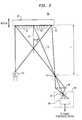
- FIG. 1there is shown a top view of a Moire distance measurement system 10 using a projection grating 18 as disclosed in commonly assigned U. S. Patent 4,988,886.
- the system 10comprises a first optical system 12(shown within a dashed line rectangle) and a second optical system 30 (shown within a dashed line rectangle) which are used for Moire distance measurements of a diffusely reflective surface 22 of an object or support 24.
- the first optical system 12comprises a light source 14, a condenser lens 16, a first grating 18, and a projection lens 20.
- the light source 14projects a beam of light through the condenser lens 16, the first grating 18, and the projection lens 20.
- the projection lens 20is used to form an image (not shown) of the first grating 18 onto the diffusely reflective surface 22 of the object or support 24.
- An optical axis 26 of the projection lens 20is arranged at an angle - ⁇ from a line 28 normal to the diffusely reflective surface 22.
- the first grating 20may comprise, for example, a Ronchi ruling including a plurality of parallel wires or opaque lines with a period "P" there between.
- the second optical system 30comprises an imaging means 32 (hereinafter referred to as a viewing lens), a second grating 34 and detector means 36.
- Viewing lens 32is positioned at a preselected distance (an initial position) "L" from the diffusely reflective surface 22 so as to facilitate reimaging of the projected image of the first grating 18, as found on the diffusely reflective surface 22, onto the second grating 34.
- System 10is useful to accurately measure changes in position as the object 24 is moved parallel to line 28.
- the viewing lens 32comprises an optical axis 38 arranged at the angle ⁇ with respect to the line 28.
- the resulting Moire patternis imaged and received by the detector means 36.
- Detector means 36comprises the lens 40 which focuses the Moire pattern onto a linear or area array 42 of optical sensing elements.
- the detector means 36can comprise any suitable device such as a human eye, a photodetector, or a video camera.
- the changes in the Moire pattern found in the output signal from detector means 36, as the diffusely reflective surface 22 moves in a direction parallel to the normal 28,can be processed by any suitable processing system (not shown).
- the image of the first grating 18is reimaged onto the second grating 34 by lens 32.
- the reimage of the first grating 18 onto the second grating 34 and the second grating 34are congruent (i.e., have the same period and are aligned in parallel).
- the resulting Moire patternis a uniform field that changes from bright to dark to bright (i.e., shift by one fringe period) forming one contour interval "C", as the diffusely reflective surface 22 moves a predetermined distance in a direction parallel to line 28.
- the diffusely reflective surface 20has moved one contour interval "C" when the image of the projected first grating 18 is displaced relative to the second grating 36 by the period of the gratings 18 and 34.
- the image of the projected first grating 18, found on diffusely reflective surface 22,is reimaged by the second lens 32 onto the second grating 34 which also has a period P.
- the reimage of the image of the first grating 18 and the second grating 34 itselfare superimposed so that the transmitted light pattern seen by detector means 36 is the product (generally denoted as the Moire) of the two gratings. With the first and second grating lines being parallel, this transmitted light pattern seen by the detector means 36 is of uniform average intensity.
- the two grating patternsoverlap and thus appear as one, and the average intensity is one half of the intensity that would be measured if there were no gratings in the system. More particularly, the transmission through a single grating is assumed to be one half intensity since the grating lines block one half the light, and it is also assumed that the individual grating lines are not resolved by the detector means 36.
- the two grating patternshave a relative shift of a half period, the bright areas of the image of the projected first grating 18 from the diffusely reflective surface 22 are shifted and blocked by the lines of the second grating 34, and the detected intensity at the detector means 36 is zero. Therefore, as one grating is laterally shifted relative to the other by the movement of the diffusely reflective surface 22 in a particular direction, the transmitted average intensity seen by the detector means 36 varies periodically from a maximum intensity to a zero intensity and back again.
- the image of the projected grating on the surface 22will appear to shift from side to side because this pattern will remain centered on the optical axis 26 of the projection lens 20.
- This shiftis due to the obliquity built into the arrangement 10 by placing the first optical system 12 at an angle ⁇ with respect to the translation direction of the diffusely reflective surface 22.
- the Moire pattern seen by the detector means 36is formed by the superposition of the reimage of the projected image of the first grating 18 on the second grating 34, it is easier to visualize that the Moire pattern is formed on the diffusely reflective surface 22.
- the symmetry of the system 10 of FIG. 1calls for a second grating 34 with the same period P as the first grating 18.
- An image of the second grating 34 on the diffusely reflective surface 22then has the same period, but an opposite directional shift, as the image of the first grating 18 when the diffusely reflective surface 22 moves parallel to line 28.
- One contour interval "C”is deemed to be the longitudinal motion of the reflective surface 22 required to shift the two grating images relative to each other by one period P0 (i.e., bright to dark to bright).
- P0i.e., bright to dark to bright.
- FIG. 1shows the system 10 as being symmetrical about line 28 for purposes of simplicity of description, but the above results could also be accomplished with non-symmetric arrangements or with two gratings tilted relative to each other.
- each arrangementwill have a contour interval C specific to that arrangement. Then, by counting the number of cycles of intensity change in the Moire pattern with, for example, a photocell, the distance, in terms of contour intervals, that the diffusely reflective surface 22 has translated can be determined. The physical displacement can then be obtained through the conversion in Equation (4) using any suitable processing system.
- System 50comprises a first grating 52, a lens 54, a second grating 56, and a detector means 58.
- the first grating 52has a predetermined period P0 and is printed on, or physically attached to, a diffusely reflective surface 60 of an object or support 62.
- An image of the first grating 52is formed by the lens 54 on the second grating 56.
- the lens 54comprises an optical axis 72 arranged at the angle ⁇ with respect to the line 70 normal to the diffusely reflective surface 60.
- the combination of the image of the first grating 52 and the second grating 56itself forms a Moire pattern.
- the detector means 58comprises a lens 64 which focuses the Moire pattern onto a linear or area array 66 of optical sensing elements.
- detector means 58can comprise any suitable device such as a human eye, a photocell, or a video camera.
- the combination of the lens 54, the second grating 56, and detector means 58are similar to the elements of the second optical system 30 of FIG. 1.
- the major difference between system 50 of FIG. 2 and system 10 of FIG. 1is that the first optical system 12 of FIG. 1 is essentially eliminated, and a first grating 52 with a period P0 has been placed on the diffusely reflective surface 60 and illuminated by a light source 68.
- system 50has fewer components than system 10 of FIG. 1.
- the light source 68 in FIG. 2is an unstructured light source (e.g., a light bulb) which can be placed anywhere to provide enough light to image the Moire pattern on the detector means 58.
- the period P0 of the first grating 52 in FIG. 2is assumed to be the same as the period P0 of the image of the first grating 18 on diffusely reflective surface 22 in FIG. 1 as shown in Equation (1).
- the system 50 of FIG. 2functions very similarly to the system 10 of FIG. 1.
- the intensity or the Moire pattern received by the detector means 58varies periodically, and changes once per contour interval.
- the period of the grating pattern imaged from the diffusely reflective surface 22 onto the second grating 34remains constant, and remains matched to the period of the second grating 34.
- the matched gratingsremain matched as the diffusely reflective surface 22 of the object or support 24 translates, and the grating images at the detector means 36 uniformly shift relative to each other over the entire Moire pattern.
- magnification change compensationdoes not take place since there is only one optical system, namely the equivalent of second optical system 30 of FIG. 1 with the printed grating 52 on the diffusely reflective surface 60. Therefore, as the diffusely reflective surface 60 translates parallel to the line 70, a magnification mismatch occurs between the two grating patterns at second grating 56.
- the magnification mismatchmanifests itself as a spatially varying intensity pattern caused by the Moire between a first and second grating pattern of different periods that is seen by the detector means 58.
- a low spatial frequency beat pattern, generated by the different periodshas a period that decreases as the mismatch between the gratings increases, and for no mismatch, the beat period is infinite. Therefore, at the initial position for the Moire distance measurement, there is no beat pattern where the gratings patterns at second grating 56 match. As the object or support 62 moves away from this initial position, the beat frequency of the resulting Moire pattern increases.
- the beat patternalso appears to move across the image seen by the detector means 58, so that over a small area of the Moire pattern the needed periodic change in intensity still occurs to encode the amount of translation of the diffusely reflective surface 60.
- One way to view this magnification change for the system 50 of FIG. 2is that the contour interval C varies across the field of view of the lens 54 (corresponding to different points on the second grating 56), and that for each location the contour interval C is constant.
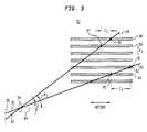
- FIG. 3there is shown a diagram including a plurality of parallel dashed rectangular areas (four of which are shown with reference numbers 88, 89, 92 and 93) associated with the first grating 52, the lens 54 with an axis 84, the second grating 56, and first and second rays of light designated 81 and 82 which are oriented at different viewing angles ⁇ 1 and ⁇ 2,respectively, from second grating 56 to the dashed rectangular areas.
- FIG. 3is useful to explain the variation in contour intervals relative to the viewing angles, and provides an understanding of the statement above that each location has a constant contour interval. It is to be understood that the dashed horizontal rectangular areas are not actual grating lines.
- these dashed rectangular areasrepresent the volumes of space that are swept out by the lines of the first grating 52 as the diffusely reflective surface 60 of FIG. 2 translates (moves from one position to another). Additionally, these horizontal rectangular areas maintain a fixed period or spacing P0 corresponding to the period of the first grating 52.
- the contour interval C for each of these rays, or detector means sensing elementsis found by determining the distance in the z-axis direction (parallel to the translation direction of the diffusely reflective surface 60) between intersections of a given ray and the centers of adjacent volumes of space of the grating lines of first grating 52.
- the distance between the intersection of ray 81 and each of the centers 86 and 87 of adjacent dashed volumes of space 88 and 89, respectively,is labeled C1.
- the distance between the intersection of ray 82 and the centers 90 and 91 of adjacent volumes of space 92 and 93is labeled C2. It is important to note that when the diffusely reflective surface 60 of FIG. 2 translates a predetermined distance C1, ray 81 moves between the centers of the adjacent volumes of space 88 and 89.
- contour intervals for rays 81 and 82are, therefore, different and are equal to the distances C1 and C2,respectively.
- the value of the contour interval as shown in equation (6)is needed. Since this value of the contour interval depends on several factors such as detector location, a solution is to experimentally calibrate the system 50 of FIG. 2.
- the system 50is set up with known dimensions, and the object or support 62, with diffusely reflective surface 60 and first grating 52, is translated a known distance parallel to the line 70.
- the resultant measurementindicates a certain number of contour intervals. Then, by dividing the known distance by the measured number of contour intervals, the value of the contour interval for the setup of arrangement 50 is obtained.
- the diffusely reflective surface 60is located at the initial distance L, the image of first grating 52 is superimposed on and matches the period P of the second grating 56 by lens 54. Therefore, the resulting Moire pattern appears as uniformly spaced alternating bright and dark vertical lines having a period P when the lines of the image of the first grating are aligned with the lines of the second grating 56.
- the diffusely reflective surface 60translates from this initial position in a first direction parallel to the line 70, not only does the image of the first grating 52 shift to one side relative to second grating 56, but the image of the first grating 52 also concurrently changes in size because of the change in the magnification factor.
- the resultis that at the center of the pattern a bright-dark-bright change is seen, while as one goes towards the edges of the Moire pattern these bright-dark-bright changes go out of phase at different rates as indicated by the changing contour interval relative to viewing angle in FIG. 3.
- first grating 52there is no strict requirement on the quality of the first grating 52.
- the first grating 52could be printed on stickers and placed on the object or support 62 as the need arises.
- the first grating 52could be molded into the part or placed on the part as a step in some other manufacturing process.
- the system 50 according to the present inventionalso works if a rotation is introduced between the first and second gratings.
- any suitable signal processing systemcan be used such as a system similar to that disclosed in commonly assigned U. S. Patent No. 4,794,550. More particularly, a computer can be used that is programmed to count the total number of contour intervals occurring in the output signal of the detector means 58. The computer can dynamically add this total number of contour intervals to a current partial contour interval detected for determining the current distance measurement.
Landscapes
- Physics & Mathematics (AREA)
- General Physics & Mathematics (AREA)
- Engineering & Computer Science (AREA)
- Optics & Photonics (AREA)
- Computer Networks & Wireless Communication (AREA)
- Electromagnetism (AREA)
- Radar, Positioning & Navigation (AREA)
- Remote Sensing (AREA)
- Length Measuring Devices By Optical Means (AREA)
- Optical Transform (AREA)
Abstract
Description
- The present invention relates to a technique for providing Moire distance measurements of a diffusely reflective surface of an object or support.
- Optically examining a surface with specular or diffuse reflection for defects during, or immediately after, a manufacturing process has included many different techniques. For example, U. S. Patent No. 2,867,149 describes a first technique which uses a grating of fine wires, or ruled lines, positioned at an angle to a surface to be measured or examined. Parallel rays of light are then projected through the grating to impinge the surface at an acute angle. When viewed from directly above the surface, the shadows of the grating elements are straight for flat surfaces and non-straight for any deviation in height of the surface. Such technique might be termed a "Zebra" test because of the pattern of light and dark areas generated on the surface. Such technique is capable of seeing surface features of a predetermined minimal size depending on the period (spacing) of the lines of the grating.
- A second technique is the well-known Ronchi test, wherein light from a light source is projected through a grating onto a curved reflective surface (e.g., a mirror) under test. The grating comprises alternating opaque and non-opaque parallel areas, and is imaged on itself. An observer images the optical curved surface under test through the grating. Therefore, in a normal Ronchi test, there is literally one grating, and both the light source and the viewing means or eye forming the observer are closely spaced and look through the single grating. In this regard, see, for example, a modified Ronchi test arrangement for measuring a flat surface described by R. W. Harrison in theIBM Technical Disclosure Bulletin, Vol. 12, No. 10, March 1970 at page 1643. In the Harrison arrangement, two lenses are needed to make up for the loss of the curved surface used in the classical Ronchi test.
- U. S. Patent No. 4,810,895 discloses a third technique for optically examining the surface of an object using Moire ray deflection mapping. With this Moire ray deflection mapping arrangement, light reflected from the surface of an object to be measured is collimated and directed through a first and a second closely spaced grating. The gratings are located at a preselected angular orientation with respect to each other to produce a Moire fringe pattern that provides an indication of the properties of the examined surface. In Moire techniques, the detector (observer/camera) is generally located immediately behind the second grating, or at the image of the first grating on the second grating. For other Moire grating arrangements see, for example, U. S. Patents 3,166,624, 3,572,924 and 3,604,813.
- Moire techniques are also used to detect a distance or displacement of a surface. Such Moire distance measuring techniques can be used for surface contour measurements or for positioning the surface of an object relative to another object or surface. For example, U. S. Patent No. 4,733,605 discloses a Moire distance measurement method and apparatus useful for the non-contact measurement of small displacements of a specularly reflective surface with a high degree of accuracy. The technique described involves projecting a collimated beam of light through a first grating onto the specularly reflective surface. The light reflected by the surface is modulated by a second grating rotated at an angle ϑ with respect to the first grating to form a Moire pattern which can be used to determine distance. A displacement of the surface causes the Moire pattern to shift, and this shift in the Moire pattern is detected and used to measure the distance moved by the surface. In general, Moire distance measuring techniques usually require both an optical grating projection system and an optical grating viewing system which have built-in equipment and implementation costs.
- It is desired to achieve measurement results of prior art Moire distance measuring systems, but to do so with a system which has fewer components and therefore reduced cost.
- The present invention is directed to a method and apparatus for Moire distance measurement. The method as claimed comprises the steps of physically locating, forming or printing a first grating on a diffusely reflective surface to be measured; forming an image of the first grating on a second grating with an imaging means for forming a Moire pattern; and detecting changes in the Moire pattern as the diffusely reflective surface moves normal to the plane thereof for providing information relating to the distance of the diffusely reflective surface relative to an initial position.
- The Moire distance measurement apparatus as claimed comprises a first grating, a second grating, an imaging means and an optical detecting means. The first grating is physically located, formed or printed on a diffusely reflective surface to be measured. The imaging means forms an image of the first grating on the second grating to generate a Moire pattern. The optical detecting means optically detects a change in the Moire pattern as the diffusely reflective surface moves in a direction normal thereto, and provides information related to a distance measurement of the diffusely reflective surface relative from an initial position.
- The invention will be better understood from the following more detailed description taken with the accompanying drawings and claims.
- FIG. 1 is a top view of an exemplary prior art arrangement for the Moire distance measurement of a diffusely reflective surface of an object or support using a projection grating;
- FIG. 2 is a top view of an arrangement for the Moire distance measurement of a diffusely reflective surface using a grating which is printed or physically located on the diffusely reflective surface in accordance with the present invention;
- FIG. 3 is a diagram for explaining the variation of the contour interval relative to viewing angle occurring with the arrangement of FIG. 2.
- The drawings are not necessarily to scale.
- Referring now to FIG. 1, there is shown a top view of a Moire
distance measurement system 10 using a projection grating 18 as disclosed in commonly assigned U. S. Patent 4,988,886. Thesystem 10 comprises a first optical system 12(shown within a dashed line rectangle) and a second optical system 30 (shown within a dashed line rectangle) which are used for Moire distance measurements of a diffuselyreflective surface 22 of an object or support 24. - The first
optical system 12 comprises alight source 14, acondenser lens 16, afirst grating 18, and aprojection lens 20. Thelight source 14 projects a beam of light through thecondenser lens 16, thefirst grating 18, and theprojection lens 20. Theprojection lens 20 is used to form an image (not shown) of thefirst grating 18 onto the diffuselyreflective surface 22 of the object or support 24. Anoptical axis 26 of theprojection lens 20 is arranged at an angle -ϑ from aline 28 normal to the diffuselyreflective surface 22. The first grating 20 may comprise, for example, a Ronchi ruling including a plurality of parallel wires or opaque lines with a period "P" there between. - The second
optical system 30 comprises an imaging means 32 (hereinafter referred to as a viewing lens), asecond grating 34 and detector means 36.Viewing lens 32 is positioned at a preselected distance (an initial position) "L" from the diffuselyreflective surface 22 so as to facilitate reimaging of the projected image of thefirst grating 18, as found on the diffuselyreflective surface 22, onto thesecond grating 34.System 10 is useful to accurately measure changes in position as theobject 24 is moved parallel toline 28. Theviewing lens 32 comprises anoptical axis 38 arranged at the angle ± with respect to theline 28. The combination of (1) the image at thesecond grating 34 of the projected image of thefirst grating 18 from the diffuselyreflective surface 22, and (2) the second grating 34 itself, form a Moire pattern (not shown). The resulting Moire pattern is imaged and received by the detector means 36. Detector means 36 comprises thelens 40 which focuses the Moire pattern onto a linear orarea array 42 of optical sensing elements. Alternatively, the detector means 36 can comprise any suitable device such as a human eye, a photodetector, or a video camera. The changes in the Moire pattern found in the output signal from detector means 36, as the diffuselyreflective surface 22 moves in a direction parallel to the normal 28, can be processed by any suitable processing system (not shown). - Several methods may be employed to detect the changing Moire pattern. In a first method, the image of the
first grating 18 is reimaged onto the second grating 34 bylens 32. The reimage of the first grating 18 onto the second grating 34 and thesecond grating 34 are congruent (i.e., have the same period and are aligned in parallel). The resulting Moire pattern is a uniform field that changes from bright to dark to bright (i.e., shift by one fringe period) forming one contour interval "C", as the diffuselyreflective surface 22 moves a predetermined distance in a direction parallel toline 28. - Deriving the relationship between the contour interval "C" and the system geometry is straight forward. The diffusely
reflective surface 20 has moved one contour interval "C" when the image of the projectedfirst grating 18 is displaced relative to thesecond grating 36 by the period of thegratings first grating 18 on the diffuselyreflective surface 22 is defined by the equation
where, P is the period offirst grating 18; and m is the optical magnification defined by the equation
where, L is the distance from diffuselyreflective surface 22 tolens 20, and f is the focal length oflens 20. - The image of the projected first grating 18, found on diffusely
reflective surface 22, is reimaged by thesecond lens 32 onto thesecond grating 34 which also has a period P. The reimage of the image of thefirst grating 18 and thesecond grating 34 itself are superimposed so that the transmitted light pattern seen by detector means 36 is the product (generally denoted as the Moire) of the two gratings. With the first and second grating lines being parallel, this transmitted light pattern seen by the detector means 36 is of uniform average intensity. - When aligned, the two grating patterns overlap and thus appear as one, and the average intensity is one half of the intensity that would be measured if there were no gratings in the system. More particularly, the transmission through a single grating is assumed to be one half intensity since the grating lines block one half the light, and it is also assumed that the individual grating lines are not resolved by the detector means 36. When the two grating patterns have a relative shift of a half period, the bright areas of the image of the projected first grating 18 from the diffusely
reflective surface 22 are shifted and blocked by the lines of thesecond grating 34, and the detected intensity at the detector means 36 is zero. Therefore, as one grating is laterally shifted relative to the other by the movement of the diffuselyreflective surface 22 in a particular direction, the transmitted average intensity seen by the detector means 36 varies periodically from a maximum intensity to a zero intensity and back again. - More particularly, as the diffusely
reflective surface 22 moves in a first and then a second opposing direction parallel toline 28, the image of the projected grating on thesurface 22 will appear to shift from side to side because this pattern will remain centered on theoptical axis 26 of theprojection lens 20. This shift is due to the obliquity built into thearrangement 10 by placing the firstoptical system 12 at an angle ϑ with respect to the translation direction of the diffuselyreflective surface 22. The shift "s" is defined by the equation
where d is the displacement of the diffuselyreflective surface 22 parallel toline 28. - Even though the Moire pattern seen by the detector means 36 is formed by the superposition of the reimage of the projected image of the
first grating 18 on thesecond grating 34, it is easier to visualize that the Moire pattern is formed on the diffuselyreflective surface 22. With such visualization, the symmetry of thesystem 10 of FIG. 1 calls for asecond grating 34 with the same period P as thefirst grating 18. An image of thesecond grating 34 on the diffuselyreflective surface 22 then has the same period, but an opposite directional shift, as the image of thefirst grating 18 when the diffuselyreflective surface 22 moves parallel toline 28. One contour interval "C" is deemed to be the longitudinal motion of thereflective surface 22 required to shift the two grating images relative to each other by one period P₀ (i.e., bright to dark to bright). For a displacement of a contour interval C, each grating will shift in its opposing direction by P₀/2 and, therefore,
- It is to be understood that FIG. 1 shows the
system 10 as being symmetrical aboutline 28 for purposes of simplicity of description, but the above results could also be accomplished with non-symmetric arrangements or with two gratings tilted relative to each other. With any of the non-symmetric arrangements, each arrangement will have a contour interval C specific to that arrangement. Then, by counting the number of cycles of intensity change in the Moire pattern with, for example, a photocell, the distance, in terms of contour intervals, that the diffuselyreflective surface 22 has translated can be determined. The physical displacement can then be obtained through the conversion in Equation (4) using any suitable processing system. - Referring now to FIG. 2, there is shown a Moire
distance measurement system 50 in accordance with the present invention.System 50 comprises afirst grating 52, alens 54, asecond grating 56, and a detector means 58. Thefirst grating 52 has a predetermined period P₀ and is printed on, or physically attached to, a diffuselyreflective surface 60 of an object orsupport 62. An image of thefirst grating 52 is formed by thelens 54 on thesecond grating 56. Thelens 54 comprises anoptical axis 72 arranged at the angle ϑ with respect to theline 70 normal to the diffuselyreflective surface 60. The combination of the image of thefirst grating 52 and thesecond grating 56 itself forms a Moire pattern. This Moire pattern is imaged onto the detector means 58. The detector means 58 comprises alens 64 which focuses the Moire pattern onto a linear orarea array 66 of optical sensing elements. Alternatively detector means 58 can comprise any suitable device such as a human eye, a photocell, or a video camera. - Essentially, the combination of the
lens 54, thesecond grating 56, and detector means 58 are similar to the elements of the secondoptical system 30 of FIG. 1. The major difference betweensystem 50 of FIG. 2 andsystem 10 of FIG. 1 is that the firstoptical system 12 of FIG. 1 is essentially eliminated, and afirst grating 52 with a period P₀ has been placed on the diffuselyreflective surface 60 and illuminated by alight source 68. Accordingly,system 50 has fewer components thansystem 10 of FIG. 1. It is to be understood, that thelight source 68 in FIG. 2 is an unstructured light source (e.g., a light bulb) which can be placed anywhere to provide enough light to image the Moire pattern on the detector means 58. It is to be understood that for purposes of description hereinafter, the period P₀ of thefirst grating 52 in FIG. 2 is assumed to be the same as the period P₀ of the image of thefirst grating 18 on diffuselyreflective surface 22 in FIG. 1 as shown in Equation (1). - To a first order, the
system 50 of FIG. 2, with the printed or physically attached first grating 52, functions very similarly to thesystem 10 of FIG. 1. As the object orsupport 62 translates parallel to theline 70, the intensity or the Moire pattern received by the detector means 58 varies periodically, and changes once per contour interval. However, without a firstoptical system 12 as found in FIG. 1, there is no obliquity in the arrangement of FIG. 2, and the expression for C differs by a factor of 2 from that of equation (4) and is defined as:
- The major difference between the operation of the
arrangements system 10 of FIG. 1, as the distance L of the diffuselyreflective surface 22 changes in a direction parallel to theline 28, the period P₀ of the pattern of the image of thefirst grating 18, found on the diffuselyreflective surface 22, changes due to the magnification change caused bylens 20. In this regard see Equation (2). However, this change in magnification bylens 18 is compensated for by thelens 32 in the secondoptical system 30 which introduces and equal and opposite magnification change. Therefore, the period of the grating pattern imaged from the diffuselyreflective surface 22 onto thesecond grating 34 remains constant, and remains matched to the period of thesecond grating 34. As a result, the matched gratings remain matched as the diffuselyreflective surface 22 of the object orsupport 24 translates, and the grating images at the detector means 36 uniformly shift relative to each other over the entire Moire pattern. - With the
system 50 of FIG. 2, however, this magnification change compensation does not take place since there is only one optical system, namely the equivalent of secondoptical system 30 of FIG. 1 with the printed grating 52 on the diffuselyreflective surface 60. Therefore, as the diffuselyreflective surface 60 translates parallel to theline 70, a magnification mismatch occurs between the two grating patterns atsecond grating 56. The magnification mismatch manifests itself as a spatially varying intensity pattern caused by the Moire between a first and second grating pattern of different periods that is seen by the detector means 58. A low spatial frequency beat pattern, generated by the different periods, has a period that decreases as the mismatch between the gratings increases, and for no mismatch, the beat period is infinite. Therefore, at the initial position for the Moire distance measurement, there is no beat pattern where the gratings patterns atsecond grating 56 match. As the object orsupport 62 moves away from this initial position, the beat frequency of the resulting Moire pattern increases. - When the diffusely
reflective surface 60 translates in a direction parallel to theline 70, the beat pattern also appears to move across the image seen by the detector means 58, so that over a small area of the Moire pattern the needed periodic change in intensity still occurs to encode the amount of translation of the diffuselyreflective surface 60. One way to view this magnification change for thesystem 50 of FIG. 2 is that the contour interval C varies across the field of view of the lens 54 (corresponding to different points on the second grating 56), and that for each location the contour interval C is constant. - Referring now to FIG. 3, there is shown a diagram including a plurality of parallel dashed rectangular areas (four of which are shown with
reference numbers first grating 52, thelens 54 with an axis 84, thesecond grating 56, and first and second rays of light designated 81 and 82 which are oriented at different viewing angles ϑ₁ and ϑ₂,respectively, fromsecond grating 56 to the dashed rectangular areas. FIG. 3 is useful to explain the variation in contour intervals relative to the viewing angles, and provides an understanding of the statement above that each location has a constant contour interval. It is to be understood that the dashed horizontal rectangular areas are not actual grating lines. Rather, these dashed rectangular areas represent the volumes of space that are swept out by the lines of thefirst grating 52 as the diffuselyreflective surface 60 of FIG. 2 translates (moves from one position to another). Additionally, these horizontal rectangular areas maintain a fixed period or spacing P₀ corresponding to the period of thefirst grating 52. - The first and second light rays labeled 81 and 82, respectively, at the respective angles ϑ₁and ϑ₂ from the axis 84 of
lens 54, represent light rays from different part of the field of view of thelens 54. It should be noted that both oflines second grating 56. These rays may also be interpreted as defining the fields of view of the elements of theoptical sensing array 66 of the detector means 58 of FIG. 2 to record the intensity measurements at each location. - The contour interval C for each of these rays, or detector means sensing elements, is found by determining the distance in the z-axis direction (parallel to the translation direction of the diffusely reflective surface 60) between intersections of a given ray and the centers of adjacent volumes of space of the grating lines of
first grating 52. For example, the distance between the intersection ofray 81 and each of thecenters space ray 82 and thecenters space reflective surface 60 of FIG. 2 translates a predetermined distance C1,ray 81 moves between the centers of the adjacent volumes ofspace - More particularly, if the diffusely
reflective surface 60, with thefirst grating 52 thereon, starts in a position where its intersection withray 81 occurs atpoint 86 ofvolume 88, a translation ofsurface 60 by a distance C₁ towardslens 54 will change the intersection ofray 81 withsurface 60 frompoint 86 ofvolume 88 to point 87 ofvolume 89. Similarly, when the diffuselyreflective surface 60, with thefirst grating 52 thereon, translates a distance C₂ towardslens 54, the intersection ofray 82 withsurface 60 will change frompoint 90 involume 92 to point 91 involume 93. This construction shows that the Moire pattern will change from light to dark to light as it traverses between adjacent lines onfirst grating 52. The contour intervals forrays 
- It is important to note that the equations for the contour intervals C₁ and C₂ use Equation (5) evaluated at two different angles, and this result simply reflects the fact that the viewing angle ϑ varies across the diffusely
reflective surface 60 of the object orsupport 62 of FIG. 2. These separate contour intervals C₁ and C₂ are also constant, as the same result is obtained anywhere along each of therays system 50 of FIG. 2 can, therefore, be interpreted to obtain a Moire distance measurement by applying the contour interval appropriate for a given location on thearray 66 of the detector means 56. To convert the number of contour intervals to a translation distance of the object orsupport 62, the value of the contour interval as shown in equation (6) is needed. Since this value of the contour interval depends on several factors such as detector location, a solution is to experimentally calibrate thesystem 50 of FIG. 2. For calibration purposes, thesystem 50 is set up with known dimensions, and the object orsupport 62, with diffuselyreflective surface 60 andfirst grating 52, is translated a known distance parallel to theline 70. The resultant measurement indicates a certain number of contour intervals. Then, by dividing the known distance by the measured number of contour intervals, the value of the contour interval for the setup ofarrangement 50 is obtained. - The following discussion is presented for providing an understanding of what is happening in the Moire pattern produced by the
system 50. When the diffuselyreflective surface 60 is located at the initial distance L, the image offirst grating 52 is superimposed on and matches the period P of thesecond grating 56 bylens 54. Therefore, the resulting Moire pattern appears as uniformly spaced alternating bright and dark vertical lines having a period P when the lines of the image of the first grating are aligned with the lines of thesecond grating 56. As the diffuselyreflective surface 60 translates from this initial position in a first direction parallel to theline 70, not only does the image of thefirst grating 52 shift to one side relative tosecond grating 56, but the image of thefirst grating 52 also concurrently changes in size because of the change in the magnification factor. The result is that at the center of the pattern a bright-dark-bright change is seen, while as one goes towards the edges of the Moire pattern these bright-dark-bright changes go out of phase at different rates as indicated by the changing contour interval relative to viewing angle in FIG. 3. - It is to be understood that the specific embodiments described herein are intended merely to be illustrative of the invention as claimed. Modifications can readily be made by those skilled in the art consistent with the principles of this invention. For example, there is no strict requirement on the quality of the
first grating 52. Thefirst grating 52 could be printed on stickers and placed on the object orsupport 62 as the need arises. For monitoring parts in production, thefirst grating 52 could be molded into the part or placed on the part as a step in some other manufacturing process. Still further, thesystem 50 according to the present invention also works if a rotation is introduced between the first and second gratings. In this case, a fixed "horizontal" Moire pattern (perpendicular to the Moire pattern introduced by the object orsupport 62 translation) appears in the image that is transmitted through thesecond grating 56. Still further, at the output of the detector means 58, any suitable signal processing system can be used such as a system similar to that disclosed in commonly assigned U. S. Patent No. 4,794,550. More particularly, a computer can be used that is programmed to count the total number of contour intervals occurring in the output signal of the detector means 58. The computer can dynamically add this total number of contour intervals to a current partial contour interval detected for determining the current distance measurement.


Claims (19)
- A method of providing Moiré distance measurements comprising the steps of:(a) physically locating, forming, or printing a first grating on a diffusely reflective surface to be measured;(b) forming an image of the first grating on a second grating with an imaging means for producing a Moiré pattern; and(c) detecting changes in the Moiré pattern as the diffusely reflective surface moves normal to a plane thereof for providing information related to the distance of the diffusely reflective surface relative from an initial position.
- The method of claim 1 wherein in step (b), arranging an optical axis of the imaging means at a predetermined acute angle with respect to a line normal to the diffusely reflective surface.
- The method of claim 1 wherein in step (b), forming the image of the first grating with a period that matches the period of the second grating when the diffusely reflective surface is located at the initial distance.
- The method of claim 3 wherein in step (b), forming the image of the first grating with a period that does not match the period of the second grating, which produces a magnification mismatch that manifests itself as a spatially varying intensity pattern caused by the Moiré between a pattern of the image of the first grating and a pattern of the second grating, when the diffusely reflective surface is not at the initial position.
- The method of claim 4 wherein in step (c) performing the substeps of:(c1) determining the dimension of a contour interval at a preselected point in the Moiré pattern, the contour interval being representative of the movement of the diffusely reflective surface required to shift the image of the first grating relative to the second grating by one period and is dependent on a predetermined viewing angle relative to an axis of the imaging means for the preselected point; and(c2) counting the number of contour intervals produced by the shifting of the image of the first grating relative to the second grating at the preselected point to determine the number of contour intervals for providing the information related to the current distance of the diffusely reflective surface relative from the initial position.
- The method of claim 1 wherein in step (c) the Moiré pattern changes are detected using a light detector.
- The method of claim 1 wherein in step (c) the Moiré pattern changes are detected using a video camera.
- Moiré distance measurement apparatus comprising:
a first grating which is physically located, formed, or printed on a diffusely reflective surface to be measured;
a second grating;
imaging means for forming an image of the first grating on the second grating to generate a Moiré pattern; and
means for optically detecting a change in the Moiré pattern as the diffusely reflective surface moves in a direction normal thereto, and for providing information related to a distance measurement of the diffusely reflective surface relative from an initial position. - The Moiré distance measurement apparatus of claim 8 wherein an optical axis of the imaging means is arranged at a predetermined acute angle with respect to a line normal to the diffusely reflective surface.
- The Moiré distance measurement apparatus of claim 8 wherein:
the first grating comprises opaque and non-opaque parallel lines or areas with a first predetermined period therebetween; and
the second grating comprises opaque and non-opaque parallel lines or areas with a second predetermined period that matches the period of the image of the first grating when the imaging means is located at the initial distance from the diffusely reflective surface. - The Moiré distance measurement apparatus of claim 10 wherein the second grating comprises a period which does not match the period of the image of the first grating when the diffusely reflective surface moves from the initial distance, whereby a magnification mismatch occurs that manifests itself as a spatially varying intensity pattern caused by the Moiré between a pattern of the image of the first grating and a pattern of the second grating.
- The Moiré distance measurement apparatus of claim 11 wherein the optical detecting means comprises means for counting the number of contour intervals produced by a shifting of the image of the first grating relative to the second grating at a preselected point in the Moiré pattern to determine the number of contour intervals for providing the information related to the current distance of the diffusely reflective surface from the initial position when the counting is started, the contour interval being representative of the movement of the diffusely reflective surface required to shift the image of the first grating relative to the second grating by one period and is dependent on a predetermined viewing angle relative to an axis of the imaging means for the preselected point.
- The Moiré distance measurement apparatus of claim 8 wherein the means for detecting comprises a light detector.
- The Moiré distance measurement apparatus of claim 13 wherein the light detector is a video camera.
- A Moiré distance measurement system for measuring the distance or displacement of a diffusely reflective surface of an object or support, the system comprising:
a first grating physically located, formed, or printed on the diffusely reflective surface comprising opaque and non-opaque parallel lines or areas with a predetermined period therebetween;
a light source for illuminating the diffusely reflective surface of the object or support;
an imaging means for forming an image of the first grating;
a second grating positioned at the image of the first grating comprising opaque and non-opaque parallel lines with a predetermined period that matches the period of the image of the first grating when the imaging means is at an initial distance; and
detecting means for viewing resultant Moiré patterns produced by the first and second gratings. - The Moiré distance measurement apparatus of claim 15 wherein the second grating comprises a period which does not match the period of the image of the first grating when the diffusely reflective surface moves from the initial distance in a direction normal to the surface, whereby a magnification mismatch occurs that manifests itself as a spatially varying intensity pattern caused by the Moiré between a pattern of the image of the first grating and a pattern of the second grating.
- The Moiré distance measurement apparatus of claim 16 wherein the detecting means comprises:
means for counting the number of contour intervals produced by a shifting of the image of the first grating relative to the second grating at a preselected point in the Moiré pattern to determine the number of contour intervals for providing the information related to the current distance of the diffusely reflective surface from the initial position, the contour interval being representative of the movement of the diffusely reflective surface required to shift the image of the first grating relative to the second grating by one period and is dependent on a predetermined viewing angle relative to an axis of the imaging means for the preselected point. - The Moiré distance measurement apparatus of claim 15 wherein the detecting means comprises a light detector.
- The Moiré distance measurement apparatus of claim 18 wherein the light detector is a video camera
Applications Claiming Priority (3)
| Application Number | Priority Date | Filing Date | Title |
|---|---|---|---|
| US584984 | 1990-09-20 | ||
| US07/584,984US5075560A (en) | 1990-09-20 | 1990-09-20 | Moire distance measurements using a grating printed on or attached to a surface |
| PCT/US1991/006649WO1992005403A1 (en) | 1990-09-20 | 1991-09-17 | Moire distance measurements using a grating printed on or attached to a surface |
Publications (2)
| Publication Number | Publication Date |
|---|---|
| EP0502162A1 EP0502162A1 (en) | 1992-09-09 |
| EP0502162B1true EP0502162B1 (en) | 1994-08-17 |
Family
ID=24339580
Family Applications (1)
| Application Number | Title | Priority Date | Filing Date |
|---|---|---|---|
| EP91917131AExpired - LifetimeEP0502162B1 (en) | 1990-09-20 | 1991-09-17 | Moire distance measurements using a grating printed on or attached to a surface |
Country Status (5)
| Country | Link |
|---|---|
| US (1) | US5075560A (en) |
| EP (1) | EP0502162B1 (en) |
| JP (1) | JPH05502731A (en) |
| DE (1) | DE69103514T2 (en) |
| WO (1) | WO1992005403A1 (en) |
Families Citing this family (10)
| Publication number | Priority date | Publication date | Assignee | Title |
|---|---|---|---|---|
| US5165045A (en)* | 1991-10-10 | 1992-11-17 | Eselun Steven A | Method and apparatus for measuring displacement having parallel grating lines perpendicular to a displacement direction for diffracting a light beam |
| US5436462A (en)* | 1993-12-21 | 1995-07-25 | United Technologies Optical Systems | Video contour measurement system employing moire interferometry having a beat frequency pattern |
| US6188058B1 (en)* | 1998-09-17 | 2001-02-13 | Agilent Technologies Inc. | System for taking displacement measurements having photosensors with imaged pattern arrangement |
| US6763133B1 (en)* | 1999-05-29 | 2004-07-13 | Sun Moon University | Moire image capturing apparatus and method therefor |
| US6667826B1 (en) | 2002-03-01 | 2003-12-23 | The United States Of America As Represented By The Administrator Of The National Aeronautics And Space Administration | Chromatic modulator for high resolution CCD or APS devices |
| DE102006015792A1 (en)* | 2006-04-05 | 2007-10-18 | Isra Surface Vision Gmbh | Method and system for measuring the shape of a reflective surface |
| WO2010070553A1 (en)* | 2008-12-15 | 2010-06-24 | Koninklijke Philips Electronics N.V. | Scanning microscope. |
| TWI412725B (en)* | 2010-12-17 | 2013-10-21 | Univ Nat Taiwan Normal | The method of distance measurement and localization |
| US9587933B2 (en)* | 2015-08-07 | 2017-03-07 | General Electric Company | System and method for inspecting an object |
| DE102016204313A1 (en)* | 2016-03-16 | 2017-09-21 | Dr. Johannes Heidenhain Gesellschaft Mit Beschränkter Haftung | Optical distance sensor and position measuring device with such a distance sensor |
Family Cites Families (58)
| Publication number | Priority date | Publication date | Assignee | Title |
|---|---|---|---|---|
| US2206606A (en)* | 1939-03-21 | 1940-07-02 | Bernard M Holter | Pocket ash tray and match case |
| CH216457A (en)* | 1940-12-28 | 1941-08-31 | Genevoise Instr Physique | Photoelectric equipment for accurately locating the position of an object bearing a division. |
| US2867149A (en)* | 1953-10-05 | 1959-01-06 | Bell Telephone Labor Inc | Method of determining surface flatness |
| US2977847A (en)* | 1957-04-29 | 1961-04-04 | Univ Ohio State Res Found | Optical system for microscopes or similar instruments |
| NL224249A (en)* | 1958-01-21 | |||
| US3166624A (en)* | 1961-05-05 | 1965-01-19 | Bausch & Lomb | Moire fringe device having line grids of gradually changing pitch |
| GB1072551A (en)* | 1963-05-21 | 1967-06-21 | Pilkington Brothers Ltd | Improvements in or relating to the manufacture of flat material |
| US3330961A (en)* | 1964-04-15 | 1967-07-11 | Eastman Kodak Co | Photoelectric skip detector for use with a viscous layer applicator |
| NL6711045A (en)* | 1967-08-10 | 1969-02-12 | ||
| JPS5114039B1 (en)* | 1968-02-27 | 1976-05-06 | ||
| NL6817007A (en)* | 1968-11-28 | 1970-06-01 | ||
| DE1941731C2 (en)* | 1969-08-16 | 1973-11-15 | Fa. Carl Zeiss, 7920 Heidenheim | Device for measuring changes in position between two relatively movable parts |
| FR2076193A5 (en)* | 1970-01-06 | 1971-10-15 | Commissariat Energie Atomique | |
| GB1352839A (en)* | 1970-07-31 | 1974-05-15 | Nat Res Dev | Methods of and apparatus for effecting optical measurement and analysis |
| IT963721B (en)* | 1972-08-04 | 1974-01-21 | Gilardino Franco | OPTICAL ELECTRONIC POSITION DETECTOR ON FRINGED ROW FOR MACHINE TOOLS AND MEASURING COMPLEX BASED ON A LARGE IMAGE FROM OPTICAL LENS |
| DD98634A1 (en)* | 1972-08-25 | 1973-07-12 | ||
| US3815998A (en)* | 1972-10-30 | 1974-06-11 | Ibm | Surface contrast system and method |
| US3847484A (en)* | 1973-02-28 | 1974-11-12 | Beckman Instruments Inc | Schlieren optical system employing a laser light source |
| JPS5181646A (en)* | 1975-01-15 | 1976-07-17 | Fuji Photo Optical Co Ltd | Tokosenkirokuhohooyobisochi |
| US4202630A (en)* | 1975-01-15 | 1980-05-13 | Fuji Photo Optical Co., Ltd. | Method of and apparatus for recording surface irregularity of object |
| JPS5289361A (en)* | 1976-01-21 | 1977-07-26 | Fuji Photo Optical Co Ltd | Oscillation measuring device for body |
| US4044377A (en)* | 1976-04-28 | 1977-08-23 | Gte Laboratories Incorporated | Video target locator |
| US4051483A (en)* | 1976-09-03 | 1977-09-27 | Fuji Photo Optical Co., Ltd. | System for measuring and recording three dimensional configuration of object |
| FR2396287A1 (en)* | 1977-07-01 | 1979-01-26 | Agfa Gevaert | DEVICE AND METHOD FOR DETECTING IRREGULARITIES IN A MOVING SHEET |
| FR2412822A1 (en)* | 1977-12-08 | 1979-07-20 | Anvar | Interpolation of scaling on precision measuring instruments - employs optical system producing Moire fringes for detection by photoreceiver |
| US4139291A (en)* | 1978-02-09 | 1979-02-13 | Nasa | System and method for obtaining wide screen Schlieren photographs |
| US4212073A (en)* | 1978-12-13 | 1980-07-08 | Balasubramanian N | Method and system for surface contouring |
| US4272196A (en)* | 1979-01-12 | 1981-06-09 | Lasag S.A. | Optical sizing mask and process |
| JPS5675004A (en)* | 1979-11-26 | 1981-06-20 | Kubota Ltd | Soil treating machine with draft control mechanism |
| IL63264A (en)* | 1980-11-04 | 1986-07-31 | Israel Atomic Energy Comm | Topographical mapping system and method |
| JPS5834309A (en)* | 1981-08-25 | 1983-02-28 | Nok Corp | Noncontacting type surface nature measuring method |
| JPS5835406A (en)* | 1981-08-28 | 1983-03-02 | Canon Inc | Configuration measuring method utilizing moire fringes |
| JPS58115313A (en)* | 1981-12-29 | 1983-07-09 | Matsushita Electric Works Ltd | Detector for defect |
| JPS58169012A (en)* | 1982-03-31 | 1983-10-05 | Matsushita Electric Works Ltd | Surface defect detecting device |
| JPS58206908A (en)* | 1982-05-28 | 1983-12-02 | Dainippon Printing Co Ltd | How to detect unevenness on finished surface |
| IL66126A (en)* | 1982-06-24 | 1985-10-31 | Israel Atomic Energy Comm | Moire light-based frequency marking systems |
| IL66382A (en)* | 1982-07-23 | 1988-04-29 | Israel Atomic Energy Comm | Method and apparatus for measuring linear distances using moire patterns |
| JPS5923205A (en)* | 1982-07-29 | 1984-02-06 | Fujitsu Ltd | Optical disk flatness detection device |
| US4488172A (en)* | 1982-08-18 | 1984-12-11 | Novon, Inc. | Method and apparatus for range imaging |
| US4499492A (en)* | 1982-08-18 | 1985-02-12 | Novon, Inc. | Method and apparatus for three frame range imaging |
| DE3233013A1 (en)* | 1982-09-06 | 1984-03-08 | Siemens AG, 1000 Berlin und 8000 München | OPTICAL ARRANGEMENT FOR DETECTING AND EVALUATING THE LOCATION OF AN OBJECT |
| US4525858A (en)* | 1983-01-03 | 1985-06-25 | General Electric Company | Method and apparatus for reconstruction of three-dimensional surfaces from interference fringes |
| CH660920A5 (en)* | 1983-02-03 | 1987-05-29 | Zellweger Uster Ag | METHOD AND DEVICE FOR THE AUTOMATIC DETECTION OF FAULTS IN TISSUES AND SIMILAR TEXTILES. |
| NL8401649A (en)* | 1984-05-23 | 1985-12-16 | Optische Ind De Oude Delft Nv | MEASURING SYSTEM FOR THE PRESSURE MEASUREMENT, USING A TRIANGULAR PRINCIPLE, OF THE DISTANCE BETWEEN A PARTICULAR POINT OF THE OBJECTIVE AND A REFERENCE LEVEL. |
| US4614864A (en)* | 1984-05-29 | 1986-09-30 | The Perkin-Elmer Corporation | Apparatus for detecting defocus |
| JPS60257306A (en)* | 1984-06-04 | 1985-12-19 | Baba Shiro | Moire topography device |
| US4796200A (en)* | 1986-12-09 | 1989-01-03 | Diffracto Ltd. | Target based determination of robot and sensor alignment |
| US4672564A (en)* | 1984-11-15 | 1987-06-09 | Honeywell Inc. | Method and apparatus for determining location and orientation of objects |
| US4577940A (en)* | 1984-12-19 | 1986-03-25 | Allied Corporation | Moire microscope |
| JPS61169702A (en)* | 1985-01-23 | 1986-07-31 | Hitachi Ltd | Measuring device of dynamic displacement pattern by moire method |
| DE3642051A1 (en)* | 1985-12-10 | 1987-06-11 | Canon Kk | METHOD FOR THREE-DIMENSIONAL INFORMATION PROCESSING AND DEVICE FOR RECEIVING THREE-DIMENSIONAL INFORMATION ABOUT AN OBJECT |
| NL8601876A (en)* | 1986-07-18 | 1988-02-16 | Philips Nv | DEVICE FOR SCANNING AN OPTICAL RECORD CARRIER. |
| US4776698A (en)* | 1986-08-04 | 1988-10-11 | Eastman Kodak Company | Measuring |
| US4722600A (en)* | 1986-10-14 | 1988-02-02 | Chiang Fu Pen | Apparatus and method for measuring strain |
| US4794550A (en)* | 1986-10-15 | 1988-12-27 | Eastman Kodak Company | Extended-range moire contouring |
| US4810895A (en)* | 1987-01-13 | 1989-03-07 | Rotlex Optics Ltd. | Method and apparatus for optical examination of an object particularly by moire ray deflection mapping |
| US4988886A (en)* | 1989-04-06 | 1991-01-29 | Eastman Kodak Company | Moire distance measurement method and apparatus |
| US5003600A (en)* | 1989-08-03 | 1991-03-26 | The United States Of America As Represented By The Department Of Energy | Diffraction gratings used as identifying markers |
- 1990
- 1990-09-20USUS07/584,984patent/US5075560A/ennot_activeExpired - Fee Related
- 1991
- 1991-09-17JPJP3516168Apatent/JPH05502731A/enactivePending
- 1991-09-17EPEP91917131Apatent/EP0502162B1/ennot_activeExpired - Lifetime
- 1991-09-17DEDE69103514Tpatent/DE69103514T2/ennot_activeExpired - Fee Related
- 1991-09-17WOPCT/US1991/006649patent/WO1992005403A1/enactiveIP Right Grant
Also Published As
| Publication number | Publication date |
|---|---|
| DE69103514T2 (en) | 1994-12-08 |
| DE69103514D1 (en) | 1994-09-22 |
| WO1992005403A1 (en) | 1992-04-02 |
| EP0502162A1 (en) | 1992-09-09 |
| US5075560A (en) | 1991-12-24 |
| JPH05502731A (en) | 1993-05-13 |
Similar Documents
| Publication | Publication Date | Title |
|---|---|---|
| US5075562A (en) | Method and apparatus for absolute Moire distance measurements using a grating printed on or attached to a surface | |
| US4988886A (en) | Moire distance measurement method and apparatus | |
| US5175601A (en) | High-speed 3-D surface measurement surface inspection and reverse-CAD system | |
| US5311286A (en) | Apparatus and method for optically measuring a surface | |
| US5289264A (en) | Method and apparatus for ascertaining the absolute coordinates of an object | |
| US5636025A (en) | System for optically measuring the surface contour of a part using more fringe techniques | |
| EP0551955B1 (en) | System for determining the topography of a curved surface | |
| US4340306A (en) | Optical system for surface topography measurement | |
| US6268923B1 (en) | Optical method and system for measuring three-dimensional surface topography of an object having a surface contour | |
| US5069548A (en) | Field shift moire system | |
| US5155363A (en) | Method for direct phase measurement of radiation, particularly light radiation, and apparatus for performing the method | |
| US5085502A (en) | Method and apparatus for digital morie profilometry calibrated for accurate conversion of phase information into distance measurements in a plurality of directions | |
| Reid | Moiré fringes in metrology | |
| JPS60235424A (en) | Overlay error measuring device between wafer pattern and mask pattern projected on same wafer | |
| EP0877914A1 (en) | Scanning phase measuring method and system for an object at a vision station | |
| US4572628A (en) | Method of and apparatus for measuring radius | |
| EP0502162B1 (en) | Moire distance measurements using a grating printed on or attached to a surface | |
| EP0140029B1 (en) | Optical distance measuring apparatus | |
| US6771362B2 (en) | Method and apparatus for testing and mapping phase objects | |
| EP0024167A2 (en) | Method and apparatus for speckle pattern interferometric determination of point displacements | |
| US4113388A (en) | Optical apparatus for determining relative positioning of two members | |
| US5212507A (en) | Apparatus for measuring cornea shape | |
| US5383025A (en) | Optical surface flatness measurement apparatus | |
| Zumbrunn | Systematic pointing errors with retroreflective targets | |
| RU2078305C1 (en) | Interference method of test of geometric positioning of lenses and interference device for its implementation |
Legal Events
| Date | Code | Title | Description |
|---|---|---|---|
| PUAI | Public reference made under article 153(3) epc to a published international application that has entered the european phase | Free format text:ORIGINAL CODE: 0009012 | |
| 17P | Request for examination filed | Effective date:19920504 | |
| AK | Designated contracting states | Kind code of ref document:A1 Designated state(s):BE DE FR GB NL | |
| 17Q | First examination report despatched | Effective date:19931011 | |
| GRAA | (expected) grant | Free format text:ORIGINAL CODE: 0009210 | |
| AK | Designated contracting states | Kind code of ref document:B1 Designated state(s):BE DE FR GB NL | |
| REF | Corresponds to: | Ref document number:69103514 Country of ref document:DE Date of ref document:19940922 | |
| ET | Fr: translation filed | ||
| PLBE | No opposition filed within time limit | Free format text:ORIGINAL CODE: 0009261 | |
| STAA | Information on the status of an ep patent application or granted ep patent | Free format text:STATUS: NO OPPOSITION FILED WITHIN TIME LIMIT | |
| 26N | No opposition filed | ||
| PGFP | Annual fee paid to national office [announced via postgrant information from national office to epo] | Ref country code:NL Payment date:19970625 Year of fee payment:7 | |
| PGFP | Annual fee paid to national office [announced via postgrant information from national office to epo] | Ref country code:GB Payment date:19970804 Year of fee payment:7 | |
| PGFP | Annual fee paid to national office [announced via postgrant information from national office to epo] | Ref country code:FR Payment date:19970905 Year of fee payment:7 | |
| PGFP | Annual fee paid to national office [announced via postgrant information from national office to epo] | Ref country code:DE Payment date:19970930 Year of fee payment:7 | |
| PGFP | Annual fee paid to national office [announced via postgrant information from national office to epo] | Ref country code:BE Payment date:19971007 Year of fee payment:7 | |
| PG25 | Lapsed in a contracting state [announced via postgrant information from national office to epo] | Ref country code:GB Free format text:LAPSE BECAUSE OF NON-PAYMENT OF DUE FEES Effective date:19980917 | |
| PG25 | Lapsed in a contracting state [announced via postgrant information from national office to epo] | Ref country code:BE Free format text:LAPSE BECAUSE OF NON-PAYMENT OF DUE FEES Effective date:19980930 | |
| BERE | Be: lapsed | Owner name:EASTMAN KODAK CY Effective date:19980930 | |
| PG25 | Lapsed in a contracting state [announced via postgrant information from national office to epo] | Ref country code:NL Free format text:LAPSE BECAUSE OF NON-PAYMENT OF DUE FEES Effective date:19990401 | |
| GBPC | Gb: european patent ceased through non-payment of renewal fee | Effective date:19980917 | |
| PG25 | Lapsed in a contracting state [announced via postgrant information from national office to epo] | Ref country code:FR Free format text:LAPSE BECAUSE OF NON-PAYMENT OF DUE FEES Effective date:19990531 | |
| NLV4 | Nl: lapsed or anulled due to non-payment of the annual fee | Effective date:19990401 | |
| PG25 | Lapsed in a contracting state [announced via postgrant information from national office to epo] | Ref country code:DE Free format text:LAPSE BECAUSE OF NON-PAYMENT OF DUE FEES Effective date:19990701 | |
| REG | Reference to a national code | Ref country code:FR Ref legal event code:ST |