EP0501820B1 - Extendible telephone - Google Patents
Extendible telephoneDownload PDFInfo
- Publication number
- EP0501820B1 EP0501820B1EP92301719AEP92301719AEP0501820B1EP 0501820 B1EP0501820 B1EP 0501820B1EP 92301719 AEP92301719 AEP 92301719AEP 92301719 AEP92301719 AEP 92301719AEP 0501820 B1EP0501820 B1EP 0501820B1
- Authority
- EP
- European Patent Office
- Prior art keywords
- casing
- main casing
- telephone
- pair
- auxiliary
- Prior art date
- Legal status (The legal status is an assumption and is not a legal conclusion. Google has not performed a legal analysis and makes no representation as to the accuracy of the status listed.)
- Expired - Lifetime
Links
Images


Classifications
- H—ELECTRICITY
- H04—ELECTRIC COMMUNICATION TECHNIQUE
- H04M—TELEPHONIC COMMUNICATION
- H04M1/00—Substation equipment, e.g. for use by subscribers
- H—ELECTRICITY
- H04—ELECTRIC COMMUNICATION TECHNIQUE
- H04M—TELEPHONIC COMMUNICATION
- H04M1/00—Substation equipment, e.g. for use by subscribers
- H04M1/02—Constructional features of telephone sets
- H04M1/0202—Portable telephone sets, e.g. cordless phones, mobile phones or bar type handsets
- H04M1/0206—Portable telephones comprising a plurality of mechanically joined movable body parts, e.g. hinged housings
- H04M1/0208—Portable telephones comprising a plurality of mechanically joined movable body parts, e.g. hinged housings characterized by the relative motions of the body parts
- H04M1/0235—Slidable or telescopic telephones, i.e. with a relative translation movement of the body parts; Telephones using a combination of translation and other relative motions of the body parts
- H04M1/0237—Sliding mechanism with one degree of freedom
- H—ELECTRICITY
- H04—ELECTRIC COMMUNICATION TECHNIQUE
- H04M—TELEPHONIC COMMUNICATION
- H04M1/00—Substation equipment, e.g. for use by subscribers
- H04M1/02—Constructional features of telephone sets
- H04M1/0202—Portable telephone sets, e.g. cordless phones, mobile phones or bar type handsets
- H—ELECTRICITY
- H04—ELECTRIC COMMUNICATION TECHNIQUE
- H04M—TELEPHONIC COMMUNICATION
- H04M1/00—Substation equipment, e.g. for use by subscribers
- H04M1/02—Constructional features of telephone sets
- H04M1/03—Constructional features of telephone transmitters or receivers, e.g. telephone hand-sets
Definitions
- the present inventionrelates to an improved extendible telephone having a body casing or main casing incorporating a receiver and an operation casing or auxiliary casing incorporating a transmitter and dial keys.
- a portable radio telephonefor example, should preferably be small size and light weight since it is carried by the user. It is a common practice with this kind of telephone to connect an auxiliary casing having a transmitter foldably or openably to a main casing having a receiver and dial keys by a hinge mechanism. To use the telephone, the user unfolds or opens the auxiliary casing away from the main casing to a position where a desired angle for conversation is set up and the receiver and transmitter are spaced apart by a desired distance.
- the hinge mechanismis relatively bulky since it has to have a sufficient mechanical strength, obstructing the decrease in the size and weight of the telephone while degrading portability.
- wirings between the main and auxiliary casingsshould be set up by way of the hinge mechanism and are, therefore, troublesome to in turn complicate the assembly of the telephone.
- An extendible telephoneas distinguished from a foldable telephone, is also conventional.
- an auxiliary casing having a transmitter and dial keysis slidably mounted on a main casing having a receiver by a guide mechanism.
- the auxiliary casingis slid via the guide mechanism to an extended position where the receiver and the transmitter are spaced apart by a desired Distance.
- the auxiliary casingis contracted to a position suitable for the telephone to be put in, for example, the user's pocket.
- the extendible telephonehas the guide mechanism having guides and guide channels thereof exposed to the outside of the main and auxiliary casing, not only the appearance is degraded, but also the design freedom is limited.
- the guide mechanismcauses the guides and guide channels to slide on each other during extension and contraction, causing the main and auxiliary casings to wear. It follows that at least the contacting portions of the telephone, i. e. , the main and auxiliary casings have to be made of a material which are high slidable and resistive to wear, increasing the cost of the telephone. Furthermore, replacing the main and auxiliary casings and due to wear is troublesome and further increases the cost of the the telephone.
- an object of the present inventionto provide an extendible telephone which is small size, light weight and highly portable.
- an extendible telephonehaving a main casing provided at least with a receiver and a slide surface, and an auxiliary casing provided at least with a transmitter and mounted on the main casing to be extendible from the main casing in a sliding motion
- a back plate memberfastened to the back of the auxiliary casing which faces the slide surface of the main casing, slide members intervening between the slide surface of the main casing and the back plate member for allowing the auxiliary casing to slide relative to the main casing to either of an extended position and a contracted position, and a support member for connecting the back plate member slidably to the slide surface of the main casing via the slide members.
- the foldable telephonegenerally 10
- the foldable telephonehas a main casing 12, an auxiliary casing 18, and a hinge mechanism 22 including a shaft 22a on which the auxiliary casing 18 is mounted to be rotatable toward and away from the main casing 12.
- the main casing 12is provided with a receiver 14 and dial keys 16 while the auxiliary casing 18 is provided with a transmitter 20.
- the userrotates or unfolds the auxiliary casing 18 about the shaft 22a in a direction indicated by an arrow A in FIG. 1B.
- the auxiliary casing 18is locked on reaching a position indicated by a phantom line in FIGS.
- a position there a desired angle for conversationis provided between the main and auxiliary casings 12 and 18 and a desired distance is provided between the receiver 14 and the transmitter 20.
- the userfolds the auxiliary casing 18 in a direction B to a position indicated by a solid line in the figures and may put the telephone 10 in, for example, a pocket.
- the problem with the foldable telephone 10is that the hinge mechanism 22 is exposed to the outside of the main and auxiliary casings 12 and 18 for structural reasons, limiting the design freedom, as discussed earlier.
- the hinge mechanism 22is bulky since it has to have a mechanical strength great enough to withstand the opening and closing motion of the auxiliary casing 18, obstructing the decrease in the size and weight of the telephone 10 while degrading portability.
- wirings between the main and auxiliary casings 18should be set up by way of the hinge mechanism 22 and are, therefore, troublesome to in turn complicate the assembly of the telephone 10.
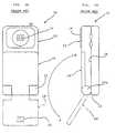
- FIGS. 2A and 2Bshow a conventional extendible telephone, generally 24.
- the extendible telephone 24has a main casing 26 including a receiver 28.
- An auxiliary casing 30is slidably mounted on the main casing 26, i. e., extendible from the main casing 26 and includes a transmitter 32 and dial keys 34.
- a rectangular hole 26bis formed through the main casing 26.
- a stop 36is formed by bending a leaf spring and received in the hole 26b while partly protruding from the surface 26a of the main casing 26 on which the auxiliary casing 30 is slidable.
- Guide channels 38are formed on laterally opposite ends of the main casing 26.
- a back plate 40is affixed to the back of the auxiliary casing 30 and formed with two positioning holes 40a and 40b which are spaced apart by a predetermined distance in the longitudinal direction of the plate 40.
- Guides 42are formed on the inner periphery of opposite side walls of the auxiliary casing 30, and each has a generally L-shaped cross-section. The guides 42 of the auxiliary casing 30 mate with the guide channels 38 of the main casing 26.
- the auxiliary casing 30is mounted on the main casing 26 by having the guides 42 thereof mated with the guide channels 38 and then being slid in a direction C until the postioning hole 40b mates with the stop 36.
- the auxiliary casing 30 with the back plate 40is extended from the main casing 26, so that the telephone 24 may be used.
- FIG. 2Cwhen the auxiliary casing 30 is further slid in the direction C on the main casing 26 until the other positioning hole 40a mates with the stop 36, the casing 30 fulls lies on the sliding surface 26a of the casing 26. In such a contracted position, the telephone 24 may be put in, for example, the user's pocket.
- the edge of the positioning hole 40a abutting against the stop 36is arcuate.
- the casing 30moves in the direction D while pressing the stop 36 downward along the arcuate edge 44 thereof.
- the auxiliary casing 30is movable in the direction D to the previously stated position of FIG. 2B.
- the guide channels 38 and guides 42 of the telephone 24are exposed to the outside, they not only degrade the appearance of the telephone 24 but also limit the design freedom.
- the guide channels 38 and guides 42slide on each other during extension and contraction, causing the main and auxiliary casings 26 and 30 to wear.
- the casings 26 and 30have to be made of a material which is highly slidable and resistive to wear, increasing the cost of the telephone 24.
- replacing the main and auxiliary casings 26 and 30 due to wearis troublesome and further increases the cost.
- an extendible telephone embodying the present inventionis shown and generally designated by the reference numeral 50.
- the telephone 50includes a main casing 60 having a receiver 62 and a slide surface 64.
- An auxiliary casing 70has a transmitter 72 and dial keys 74.
- a pair of rail members 80are affixed to the slide surface 64 of the main casing 60.
- a hook member 90is affixed to the back of the main casing 60 while a back plate 100 is affixed to the back of the auxiliary casing 70.
- a printed circuit board 66 and a rear cover 68are also affixed to the back of the main casing 60, and another printed circuit board 76 is affixed to the back of the auxiliary casing 70.
- a pair of grooves 60aare formed in the slide surface 64 of the main casing 60 in close proximity to opposite edges of the casing 60 and in symmetrical positions in the lateral direction.
- the grooves 60ahave such a length that they will not be exposed to the outside when the auxiliary casing 70 is extended from the main casing 60 to a position where the telephone 50 is usable.
- Each groove 60ais deeper at an intermediate portion than at opposite end portions with respect to the longitudinal direction, i. e., in the extendible direction of the telephone 50.
- a pair of guide slots 60bextend in parallel to the grooves 60a and are located closer to opposite edges of the slide surface 64 than the grooves 60a.
- the guide slots 60bhave a length corresponding to a distance over which the auxiliary casing 70 is movable relative to the main casing 60.
- a pair of rectangular holes 60care each positioned above and in alignment with respective one of the guide slots 60b.
- the main casing 60is provided with a hole 60d and a pawl 60e at, respectively, the upper edge and the lower edge of the slide surface 64.
- the auxiliary casing 60has a lug 70a at the upper edge thereof which mates with the hole 60d and a hole 70b at the lower edge which mates with the pawl 60e.
- the rail members 80have a configuration complementary to the configuration of the grooves 60a of the main casing 60, and each is made up of a flat portion 80a and a bulged portion 80b extending in the longitudinal direction of the flat portion 80a. Further, each rail member 80 has pawls 80c and 80d at opposite ends thereof, and an angled lug 80e located substantially at the center of the bulged portion 80b. A pair of pawls 90a extend from opposite ends of the hook member 90 and extend throughout the pair of rectangular holes 60c of the main casing 60.
- the back plate 100On the surface facing the slide surface 64 of the main casing 60, the back plate 100 has a pair of pawls 100a to be slidably received in the guide slots 60b of the main casing 60, two spaced pairs of angled recesses 100b and 100c selectively engageable wth the angled lugs 80e of the rail members 80, and an elongate recess or guide 100d for receiving the lug 60e of the main casing 60 while the casing 70 slides relative to the casing 60. Further, the back plate 100 has a pair of guide grooves 100e for allowing the pawls 90a of the hooks 90 to slide therein.
- the printed circuit board 76is fastened to the auxiliary casing 70 by screws 78, and then the back plate 100 is fastened to the same by screws 102 over the circuit board 76 to form an auxiliary casing subassembly.
- the pawls 100a of the back plate 100 included in the subassemblyare press-fitted in the guide slots 60b.
- the pawls 90a of the hook member 90are press-fitted in the guide grooves 100e of the back plate 100 via the rectangular holes 60c and from the rear of the main casing 60.
- FIG. 4Ashows the connection of the main casing 60 and the back plate 100 of the auxiliary casing 70
- FIG. 4Bshows the connection of the main casing 60 and the back plate 100 and hook member 90.
- FIGS. 5A and 5BA reference will be made to FIGS. 5A and 5B for describing the extension and contraction of the auxiliary casing 70 relative to the main casing 60.
- the auxiliary casing 70in the contracted position, has the lug 70a thereof received in the hole 60d of the main casing 60 and, in turn, receives the pawl 60e of of the latter in the hole 70b thereof.
- the casing 70is firmly retained by the casing 60.
- the casing 70slides along the bulged portions 80b of the rail members 80 which are fitted in the casing 60.
- the pawls 100a of the back plate 100 and the pawls 90a of the hook member 90are guided respectively by the guide slots 60b of the casing 60 and the guide grooves 100e of the back plate 100.
- the casing 70is fully extended out from the casing 60, as shown in FIG. 5B.
- FIG. 6Ashows the auxiliary casing 70 in the contracted position while FIG. 6B shows it in the extended position.
- FIGS. 7A and 7Bare fragmentary enlarged views associated with FIGS. 6A and 6B, respectively.
- the angled lug 80e of each rail member 80is fully received in the associated lower angled recess 100b of the back plate 100, locking the rail member 80 in position.
- the casing 70is pulled in the direction E by a force exceeding predetermined one, the lug 80e is released from the recess 100b and pressed by the back plate 100.
- the rail members 80, hook member 90 and back plate 100 which allow the auxiliary casing 70 to slide on the main casing 60are preferably made of resin or similar material having high wear resistance and slidableness.
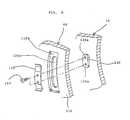
- FIG. 8shows a modified form of the extendible telephone 50.
- this embodimentdoes not have the rail members 80, hook member 90 or back plate 100 and, instead, provides the main casing 60 with a pair of parallel wall portions 110 in close proximity to opposite edges of the slide surface 64 thereof.
- FIG. 8shows only one of the wall portions 110 which adjoins the right side edge as viewed in FIG. 3.
- an elongate slot 110ais formed through the wall portion 110 and surrounded by a seat portion, or stepped portion, 110b.
- Projections 120(only one is shown) are provided on the inner surface of the auxiliary casing 70 in alignment with the wall portions 110, and each mates with one of the slots 110a when the telephone 50 is assembled. Threaded holes 120a are formed in each projection 120.
- a leaf spring 130is fastened to each projection 120 by screws 140 which are driven into the threaded holes 120a, while resting on the seat portion 110b. Since the leaf spring 130 is angled, it tends to pull the projection 120, i. e., the casing 70 toward the casing 60 when fastened to the projection 120. Therefore, the casing 70 constantly biased by the leaf spring 130 does not slide relative to the casing 60 while it is free from external forces. When the user pulls or presses the casing 70, the casing 70 is ready to slide on the casing 60.
- the slot 110afunctions to delimit the slidable range of the casing 70.
- the length of the slot 110ais selected such that the casing 70 fully lies on the slide surface 64 of the casing 60 when the projection 120 abuts against one end of the slot 110a or fully extends from the casing 60 when the former abuts against the other end of the latter.
- the casings 60 and 70may be provided with the projections 120 and the slots 110a, respectively, contrary to the above modification.
- the present inventionprovides an extendible telephone which is small size, light weight and highly portable, enhances the design freedom while achieving attractive appearance, simplifies the assembly, and reduces the cost.
Landscapes
- Engineering & Computer Science (AREA)
- Signal Processing (AREA)
- Telephone Set Structure (AREA)
Description
- The present invention relates to an improved extendible telephone having a body casing or main casing incorporating a receiver and an operation casing or auxiliary casing incorporating a transmitter and dial keys.
- Various kinds of telephones extensively used today include a radio telephone to be used while in movement and a cordless telephone to be used only in a relatively narrow range, e. g. , in an office or a home. A portable radio telephone, for example, should preferably be small size and light weight since it is carried by the user. It is a common practice with this kind of telephone to connect an auxiliary casing having a transmitter foldably or openably to a main casing having a receiver and dial keys by a hinge mechanism. To use the telephone, the user unfolds or opens the auxiliary casing away from the main casing to a position where a desired angle for conversation is set up and the receiver and transmitter are spaced apart by a desired distance. While the telephone is not used, it is put in, for example, the user's pocket with the auxiliary casing folded or closed. Such a foldable telephone is disclosed in, for example, U. S. Patent No. 4, 897, 873 (Beutler et al) and japanese Patent Laid-Open Publication (Kokai) Nos. 212052/1989 and 159159/1990. The conventional foldable telephone, however, has a drawback that the hinge mechanism is exposed to the outside of the main and auxiliary casings since it cannot be readily incorporated in the main casing or the auxiliary casing, limiting the design freedom. In addition, the hinge mechanism is relatively bulky since it has to have a sufficient mechanical strength, obstructing the decrease in the size and weight of the telephone while degrading portability. Moreover, wirings between the main and auxiliary casings should be set up by way of the hinge mechanism and are, therefore, troublesome to in turn complicate the assembly of the telephone.
- An extendible telephone, as distinguished from a foldable telephone, is also conventional. In an extendible telephone, as described in DE-A-3 836 406, an auxiliary casing having a transmitter and dial keys is slidably mounted on a main casing having a receiver by a guide mechanism. To use this kind of telephone, the auxiliary casing is slid via the guide mechanism to an extended position where the receiver and the transmitter are spaced apart by a desired Distance. While the telephone is not used, the auxiliary casing is contracted to a position suitable for the telephone to be put in, for example, the user's pocket. However, since the extendible telephone has the guide mechanism having guides and guide channels thereof exposed to the outside of the main and auxiliary casing, not only the appearance is degraded, but also the design freedom is limited. The guide mechanism causes the guides and guide channels to slide on each other during extension and contraction, causing the main and auxiliary casings to wear. It follows that at least the contacting portions of the telephone, i. e. , the main and auxiliary casings have to be made of a material which are high slidable and resistive to wear, increasing the cost of the telephone. Furthermore, replacing the main and auxiliary casings and due to wear is troublesome and further increases the cost of the the telephone.
- It is, therefore, an object of the present invention to provide an extendible telephone which is small size, light weight and highly portable.
- It is another object of the present invention to provide an extendible telephone which enhances design freedom without degrading the appearance.
- It is another object of the present invention to provide an extendible telephone which promotes easy assembly and reduces the production cost.
- In accordance with the present invention, an extendible telephone having a main casing provided at least with a receiver and a slide surface, and an auxiliary casing provided at least with a transmitter and mounted on the main casing to be extendible from the main casing in a sliding motion comprises a back plate member fastened to the back of the auxiliary casing which faces the slide surface of the main casing, slide members intervening between the slide surface of the main casing and the back plate member for allowing the auxiliary casing to slide relative to the main casing to either of an extended position and a contracted position, and a support member for connecting the back plate member slidably to the slide surface of the main casing via the slide members.
- Also, in accordance with the present invention, an extendible telephone having a main casing provided at least with a receiver, and an auxiliary casing provided at least with a transmitter and mounted on the main casing to be extendible from the main casing in a sliding motion comprises a curved slide surface along which the auxiliary casing is slidable relative to the main casing, and a connecting member for connecting the auxiliary casing slidably to the main casing via the slide surface.
- The above and other objects, features and advantages of the present invention will become more apparent from the following detailed description taken with the accompanying drawings in which:
- FIG. 1A is a plan view showing a conventional foldable telephone ;
- FIG. 1B is a side elevation of the telephone shown in FIG. 1A;
- FIG. 2A is an exploded perspective view of a conventional extendible telephone;
- FIGS. 2B and 2C show how the telephone of FIG. 2A is extendible;
- FIG. 3 is an exploded perspective view of an extendible telephone embodying the present invention;
- FIGS. 4A and 4B are sections showing a main casing and an auxiliary casing included in the embodiment in a connected position;
- FIGS. 5A, 5B, 6A, 6B, 7A and 7B show how the telephone of FIG. 3 slide; and
- FIG. 8 is a fragmentary perspective view of a modified form of the embodiment.
- To better understand the present invention, a brief reference will be made to a conventional foldable telephone, shown in FIGS. 1A and 1B. As shown, the foldable telephone, generally 10, has a
main casing 12, anauxiliary casing 18, and ahinge mechanism 22 including a shaft 22a on which theauxiliary casing 18 is mounted to be rotatable toward and away from themain casing 12. Themain casing 12 is provided with areceiver 14 anddial keys 16 while theauxiliary casing 18 is provided with atransmitter 20. To use thetelephone 10, the user rotates or unfolds theauxiliary casing 18 about the shaft 22a in a direction indicated by an arrow A in FIG. 1B. Theauxiliary casing 18 is locked on reaching a position indicated by a phantom line in FIGS. 1A and 1B, i. e., a position there a desired angle for conversation is provided between the main andauxiliary casings receiver 14 and thetransmitter 20. After the conversation, the user folds theauxiliary casing 18 in a direction B to a position indicated by a solid line in the figures and may put thetelephone 10 in, for example, a pocket. The problem with thefoldable telephone 10 is that thehinge mechanism 22 is exposed to the outside of the main andauxiliary casings hinge mechanism 22 is bulky since it has to have a mechanical strength great enough to withstand the opening and closing motion of theauxiliary casing 18, obstructing the decrease in the size and weight of thetelephone 10 while degrading portability. Moreover, wirings between the main andauxiliary casings 18 should be set up by way of thehinge mechanism 22 and are, therefore, troublesome to in turn complicate the assembly of thetelephone 10. - FIGS. 2A and 2B show a conventional extendible telephone, generally 24. As shown, the
extendible telephone 24 has amain casing 26 including areceiver 28. Anauxiliary casing 30 is slidably mounted on themain casing 26, i. e., extendible from themain casing 26 and includes atransmitter 32 anddial keys 34. Arectangular hole 26b is formed through themain casing 26. Astop 36 is formed by bending a leaf spring and received in thehole 26b while partly protruding from thesurface 26a of themain casing 26 on which theauxiliary casing 30 is slidable.Guide channels 38 are formed on laterally opposite ends of themain casing 26. Aback plate 40 is affixed to the back of theauxiliary casing 30 and formed with twopositioning holes plate 40.Guides 42 are formed on the inner periphery of opposite side walls of theauxiliary casing 30, and each has a generally L-shaped cross-section. Theguides 42 of theauxiliary casing 30 mate with theguide channels 38 of themain casing 26. - As shown in FIG. 2B, the
auxiliary casing 30 is mounted on themain casing 26 by having theguides 42 thereof mated with theguide channels 38 and then being slid in a direction C until thepostioning hole 40b mates with thestop 36. Specifically, in the position shown in FIG. 2B, theauxiliary casing 30 with theback plate 40 is extended from themain casing 26, so that thetelephone 24 may be used. As shown in FIG. 2C, when theauxiliary casing 30 is further slid in the direction C on themain casing 26 until theother positioning hole 40a mates with thestop 36, thecasing 30 fulls lies on the slidingsurface 26a of thecasing 26. In such a contracted position, thetelephone 24 may be put in, for example, the user's pocket. As shown in FIG. 2C, the edge of thepositioning hole 40a abutting against thestop 36 is arcuate. Hence, when a force is exerted on theauxiliary casing 30 in a direction D, FIG. 2C, thecasing 30 moves in the direction D while pressing thestop 36 downward along thearcuate edge 44 thereof. As a result, theauxiliary casing 30 is movable in the direction D to the previously stated position of FIG. 2B. Once thepositioning hole 40b and stop 36 mate with each other, they will not be released though the force may be further exerted in the direction D, since theedge 46 of thehole 40b abutting against thestop 36 in such a positin is straight. When theauxiliary casing 30 slides on themain casing 26 during extension or contraction, a pressure acts between theback plate 40 and theslide surface 26a of thecasing 26. This is successful in exerting an adequate degree of resistance to theauxiliary casing 30 being moved by the user and in eliminating shaking. - However, since the
guide channels 38 and guides 42 of thetelephone 24 are exposed to the outside, they not only degrade the appearance of thetelephone 24 but also limit the design freedom. Theguide channels 38 and guides 42 slide on each other during extension and contraction, causing the main andauxiliary casings casings telephone 24. Furthermore, replacing the main andauxiliary casings - Referring to FIG. 3, an extendible telephone embodying the present invention is shown and generally designated by the
reference numeral 50. As shown, thetelephone 50 includes amain casing 60 having areceiver 62 and aslide surface 64. Anauxiliary casing 70 has atransmitter 72 anddial keys 74. A pair ofrail members 80 are affixed to theslide surface 64 of themain casing 60. Ahook member 90 is affixed to the back of themain casing 60 while aback plate 100 is affixed to the back of theauxiliary casing 70. A printedcircuit board 66 and arear cover 68 are also affixed to the back of themain casing 60, and another printedcircuit board 76 is affixed to the back of theauxiliary casing 70. - A pair of
grooves 60a are formed in theslide surface 64 of themain casing 60 in close proximity to opposite edges of thecasing 60 and in symmetrical positions in the lateral direction. Thegrooves 60a have such a length that they will not be exposed to the outside when theauxiliary casing 70 is extended from themain casing 60 to a position where thetelephone 50 is usable. Eachgroove 60a is deeper at an intermediate portion than at opposite end portions with respect to the longitudinal direction, i. e., in the extendible direction of thetelephone 50. A pair ofguide slots 60b extend in parallel to thegrooves 60a and are located closer to opposite edges of theslide surface 64 than thegrooves 60a. Theguide slots 60b have a length corresponding to a distance over which theauxiliary casing 70 is movable relative to themain casing 60. A pair ofrectangular holes 60c are each positioned above and in alignment with respective one of theguide slots 60b. Further, themain casing 60 is provided with ahole 60d and apawl 60e at, respectively, the upper edge and the lower edge of theslide surface 64. On the other hand, theauxiliary casing 60 has alug 70a at the upper edge thereof which mates with thehole 60d and ahole 70b at the lower edge which mates with thepawl 60e. - The
rail members 80 have a configuration complementary to the configuration of thegrooves 60a of themain casing 60, and each is made up of a flat portion 80a and a bulgedportion 80b extending in the longitudinal direction of the flat portion 80a. Further, eachrail member 80 haspawls 80c and 80d at opposite ends thereof, and anangled lug 80e located substantially at the center of the bulgedportion 80b. A pair of pawls 90a extend from opposite ends of thehook member 90 and extend throughout the pair ofrectangular holes 60c of themain casing 60. On the surface facing theslide surface 64 of themain casing 60, theback plate 100 has a pair ofpawls 100a to be slidably received in theguide slots 60b of themain casing 60, two spaced pairs ofangled recesses angled lugs 80e of therail members 80, and an elongate recess or guide 100d for receiving thelug 60e of themain casing 60 while thecasing 70 slides relative to thecasing 60. Further, theback plate 100 has a pair ofguide grooves 100e for allowing the pawls 90a of thehooks 90 to slide therein. - To assemble the
telephone 50, the printedcircuit board 76 is fastened to theauxiliary casing 70 byscrews 78, and then theback plate 100 is fastened to the same byscrews 102 over thecircuit board 76 to form an auxiliary casing subassembly. After therail members 80 have been fitted in thegrooves 60a of themain casing 60, thepawls 100a of theback plate 100 included in the subassembly are press-fitted in theguide slots 60b. Subsequently, the pawls 90a of thehook member 90 are press-fitted in theguide grooves 100e of theback plate 100 via therectangular holes 60c and from the rear of themain casing 60. As a result, theauxiliary casing 70 is connected to themain casing 60 and slidable on theslide surface 64 of the latter. Finally, the printedcircuit board 66 is affixed to the back of themain casing 60, and then therear cover 68 is affixed to thecasing 60 over thecircuit board 66. FIG. 4A shows the connection of themain casing 60 and theback plate 100 of theauxiliary casing 70, while FIG. 4B shows the connection of themain casing 60 and theback plate 100 andhook member 90. - A reference will be made to FIGS. 5A and 5B for describing the extension and contraction of the
auxiliary casing 70 relative to themain casing 60. As shown in FIG. 5A, in the contracted position, theauxiliary casing 70 has thelug 70a thereof received in thehole 60d of themain casing 60 and, in turn, receives thepawl 60e of of the latter in thehole 70b thereof. In this condition, thecasing 70 is firmly retained by thecasing 60. As a force is exerted on thecasing 70 in a direction E, FIG. 5B, thecasing 70 slides along the bulgedportions 80b of therail members 80 which are fitted in thecasing 60. At this instant, thepawls 100a of theback plate 100 and the pawls 90a of thehook member 90 are guided respectively by theguide slots 60b of thecasing 60 and theguide grooves 100e of theback plate 100. As a result, thecasing 70 is fully extended out from thecasing 60, as shown in FIG. 5B. - How the
rail members 80 move will be described with reference to FIGS. 6A, 6B, 7A and 7B. FIG. 6A shows theauxiliary casing 70 in the contracted position while FIG. 6B shows it in the extended position. FIGS. 7A and 7B are fragmentary enlarged views associated with FIGS. 6A and 6B, respectively. As best shown in FIG. 7A, in the contracted position, theangled lug 80e of eachrail member 80 is fully received in the associated lowerangled recess 100b of theback plate 100, locking therail member 80 in position. As thecasing 70 is pulled in the direction E by a force exceeding predetermined one, thelug 80e is released from therecess 100b and pressed by theback plate 100. As a result, part of theflat portion 80e of theback plate 100 where thelug 80e is position is deformed to penetrate into the deeper portion of the associatedgroove 60a of thecasing 60. When thecasing 70 is further pulled to the fully extended position shown in FIG. 7B, thelug 80e of therail member 80 is fully received in theupper recess 100c of theback plate 100, again locking therail member 80 in position. Thetelephone 50 is ready to operate in such an extended position. - In the illustrative embodiment, the
rail members 80,hook member 90 and backplate 100 which allow theauxiliary casing 70 to slide on themain casing 60 are preferably made of resin or similar material having high wear resistance and slidableness. - FIG. 8 shows a modified form of the
extendible telephone 50. As shown, this embodiment does not have therail members 80,hook member 90 or backplate 100 and, instead, provides themain casing 60 with a pair ofparallel wall portions 110 in close proximity to opposite edges of theslide surface 64 thereof. FIG. 8 shows only one of thewall portions 110 which adjoins the right side edge as viewed in FIG. 3. As shown, an elongate slot 110a is formed through thewall portion 110 and surrounded by a seat portion, or stepped portion, 110b. Projections 120 (only one is shown) are provided on the inner surface of theauxiliary casing 70 in alignment with thewall portions 110, and each mates with one of the slots 110a when thetelephone 50 is assembled. Threaded holes 120a are formed in eachprojection 120. Aleaf spring 130 is fastened to eachprojection 120 byscrews 140 which are driven into the threaded holes 120a, while resting on theseat portion 110b. Since theleaf spring 130 is angled, it tends to pull theprojection 120, i. e., thecasing 70 toward thecasing 60 when fastened to theprojection 120. Therefore, thecasing 70 constantly biased by theleaf spring 130 does not slide relative to thecasing 60 while it is free from external forces. When the user pulls or presses thecasing 70, thecasing 70 is ready to slide on thecasing 60. The slot 110a functions to delimit the slidable range of thecasing 70. Hence, the length of the slot 110a is selected such that thecasing 70 fully lies on theslide surface 64 of thecasing 60 when theprojection 120 abuts against one end of the slot 110a or fully extends from thecasing 60 when the former abuts against the other end of the latter. - If desired, the
casings projections 120 and the slots 110a, respectively, contrary to the above modification. - In summary, it will be seen that the present invention provides an extendible telephone which is small size, light weight and highly portable, enhances the design freedom while achieving attractive appearance, simplifies the assembly, and reduces the cost.
- Various modifications will become possible for those skilled in the art after receiving the teachings of the present disclosure without departing from the scope thereof.
Claims (11)
- An extendible telephone having a main casing (60) provided at least with a receiver (62) and a slide surface (64), and an auxiliary casing (70) provided at least with a transmitter (72) and mounted on said main casing to be extendible from said main casing in a sliding motion, said telephone comprising:a back plate member (100) fastened to the back of said auxiliary casing (70) which faces said slide surface of said maincasing (60);slide members (80) intervening between said slide surface of said main casing (60) and said back plate member (100) for allowing said auxiliary casing (70) to slide relative to said main casing (60) to either of an extended position and a concentrated position; anda support member (90) for connecting said back plate member (100) slidably to said slide surface of said main casing (60) via said slide members.
- A telephone as claimed in claim 1, further comprising a pair of grooves extending in a longitudinal direction on said slide surface of said main casing in close proximity to opposite side edges of said slide surface and symmetrically to each other, a pair of guide slots formed through said main casing in parallel to said pair of grooves and closer to said opposite side edges than said grooves, and a pair of rectangular holes located above and in alignment with said pair of guide slots.
- A telephone as claimed in claim 2, wherein said slide members have a configuration complementary to the configuration of said pair of grooves and each comprises a flat portion, a bulged portion extending in the longitudinal direction of said flat portion, an angled lug located at the intermediate between opposite ends of said bulged portion, and a pair of pawls located at opposite ends of said slide member.
- A telephone as claimed in claim 4, wherein said support member comprises an elongate hook having at opposite ends thereof a pair of pawls which extend throughout said pair of rectangular holes of said main casing.
- A telephone as claimed in claim 4, wherein said back plate member comprises a pair of pawls provided on the back facing said slide surface of said main casing and mating with and sliding in said pair of guide slots of said main casing, a first and a second pair of recesses spaced apart from each other by a predetermined distance and selectively engageable with said pair of angled lugs of said slide members, and a pair of guide grooves located closer to opposite side edges of said back plate member than said first and second pairs of recesses for slidably receiving said pair of pawls of said hook.
- A telephone as claimed in claim 5, further comprising a pawl formed at the lower edge of said slide surface of said main casing.
- A telephone as claimed in claim 6, wherein said back plate member further comprises an elonate guide recess for allowing said pawl of said main casing to slide therein when said auxiliary casing is slid.
- A telephone as claimed in claim 1, wherein said back plate member, said slide members and said support member are made of resin which are highly sliable and resistive to wear.
- An extendible telephone having a main casing(60) provided at least with a receiver (62), an auxiliary casing (70) provided at least with a transmitter (72) and mounted on said main casing to be extendible from said main casing in a sliding motion, said telephone comprising:a curved slide surface (64) along which said auxiliary casing a curved slide surface (64) along which said auxiliary casing is slidable relative to said main casing; andconnecting means (80, 90) for connecting said auxiliary casing slidably to said main casing via said slide surface.
- A telephone as claimed in claim 9, wherein said connecting means comprises slots formed in one of said main casing and said auxiliary casing for delimiting the slidable range of said auxiliary casing relative to said main casing, and lugs provided on the other of said main casing and said auxiliary casing.
- A telephone as claimed in claim 10, wherein said connecting means further comprising leaf springs each maintaining one of the lugs in engagement with associated one of said slots.
Applications Claiming Priority (2)
| Application Number | Priority Date | Filing Date | Title |
|---|---|---|---|
| JP57855/91 | 1991-02-28 | ||
| JP3057855AJP3016889B2 (en) | 1991-02-28 | 1991-02-28 | Mobile phone |
Publications (3)
| Publication Number | Publication Date |
|---|---|
| EP0501820A2 EP0501820A2 (en) | 1992-09-02 |
| EP0501820A3 EP0501820A3 (en) | 1993-01-13 |
| EP0501820B1true EP0501820B1 (en) | 1996-06-12 |
Family
ID=13067607
Family Applications (1)
| Application Number | Title | Priority Date | Filing Date |
|---|---|---|---|
| EP92301719AExpired - LifetimeEP0501820B1 (en) | 1991-02-28 | 1992-02-28 | Extendible telephone |
Country Status (8)
| Country | Link |
|---|---|
| US (1) | US5335274A (en) |
| EP (1) | EP0501820B1 (en) |
| JP (1) | JP3016889B2 (en) |
| KR (1) | KR960006947B1 (en) |
| AU (1) | AU642585B2 (en) |
| CA (1) | CA2061948C (en) |
| DE (1) | DE69211384T2 (en) |
| ES (1) | ES2090496T3 (en) |
Families Citing this family (41)
| Publication number | Priority date | Publication date | Assignee | Title |
|---|---|---|---|---|
| JP2581414B2 (en)* | 1993-10-08 | 1997-02-12 | 日本電気株式会社 | Portable radio |
| JP2595932B2 (en)* | 1994-05-18 | 1997-04-02 | 日本電気株式会社 | Portable radio |
| USD370673S (en) | 1995-02-21 | 1996-06-11 | Kabushiki Kaisha Toshiba | Handheld information communications terminal |
| US5661797A (en)* | 1995-11-01 | 1997-08-26 | Nokia Mobile Phones Ltd. | Hinge mechanism for cellular transceiver housing |
| USD381020S (en)* | 1996-01-19 | 1997-07-15 | Mitsubishi Electronics America, Inc. | Telephone with slidable cover |
| US5867772A (en)* | 1996-03-08 | 1999-02-02 | Ericsson, Inc. | Cellular telephone assembly and method for assembling a cellular telephone |
| USD386757S (en)* | 1996-03-13 | 1997-11-25 | Motorola, Inc. | Portable radio communication device |
| USD406131S (en)* | 1996-10-29 | 1999-02-23 | Siemens Aktiengesellschaft | Mobile radiotelephone device |
| US5999822A (en)* | 1997-03-14 | 1999-12-07 | Sony Corporation | Cellular telephone with extendible microphone |
| US6101402A (en)* | 1997-09-04 | 2000-08-08 | Ericcson Inc. | Radiotelephone with sliding acoustic member |
| US6058293A (en)* | 1997-09-12 | 2000-05-02 | Ericsson, Inc. | Frame structure for cellular telephones |
| US6026283A (en)* | 1997-12-05 | 2000-02-15 | Ericsson Inc. | Electrically conductive keypad lightguides |
| FI112759B (en)* | 1998-03-18 | 2003-12-31 | Nokia Corp | Phone Telescope |
| US6243595B1 (en)* | 1998-06-16 | 2001-06-05 | Nortel Networks Limited | Portable wireless communication device having an extendible section |
| USD423493S (en)* | 1998-06-16 | 2000-04-25 | Sony Corporation | Wireless telephone |
| USD409601S (en)* | 1998-10-14 | 1999-05-11 | Sony Corporation | Cellular telephone with extendible keyboard |
| FI116029B (en)* | 1998-12-22 | 2005-08-31 | Nokia Corp | Design of the telescopic housing of an electrical appliance |
| KR100322271B1 (en)* | 2000-03-23 | 2002-02-06 | 윤종용 | Slide key for portable radiotelephone |
| USD466096S1 (en) | 2001-08-24 | 2002-11-26 | Masahiko Takada | Mobile phone with digital camera |
| USD495323S1 (en) | 2001-11-13 | 2004-08-31 | Nokia Corporation | Portion of a handset |
| USD481692S1 (en) | 2001-11-13 | 2003-11-04 | Nokia Corporation | Handset |
| USD479215S1 (en) | 2002-01-25 | 2003-09-02 | Kabushiki Kaisha Toshiba | Portable phone |
| JP2004235897A (en)* | 2003-01-29 | 2004-08-19 | Kato Electrical Mach Co Ltd | Portable telephone and slide mechanism |
| DE10314311A1 (en)* | 2003-03-31 | 2004-10-28 | Siemens Ag | mobile device |
| KR100563696B1 (en) | 2003-09-09 | 2006-03-28 | 엘지전자 주식회사 | Slide structure of slide type mobile communication terminal |
| JP3944506B2 (en)* | 2003-10-28 | 2007-07-11 | エルジー エレクトロニクス インコーポレイティド | SLIDING TYPE PORTABLE TERMINAL AND SLIDING DEVICE USED FOR THE SAME |
| KR100576000B1 (en)* | 2003-10-29 | 2006-05-02 | 삼성전자주식회사 | Spring module of sliding type portable terminal |
| KR100608726B1 (en)* | 2003-12-09 | 2006-08-04 | 엘지전자 주식회사 | Bidirectional Sliding Handheld Terminal |
| US7660411B2 (en) | 2004-05-31 | 2010-02-09 | Mitsubishi Electric Corporation | Portable telephone |
| KR100689498B1 (en)* | 2004-11-25 | 2007-03-02 | 삼성전자주식회사 | Sliding module of sliding type mobile terminal |
| JP2006173794A (en)* | 2004-12-13 | 2006-06-29 | Kato Electrical Mach Co Ltd | Slide mechanism for mobile unit and mobile phone |
| CN100571290C (en)* | 2004-12-20 | 2009-12-16 | 诺基亚公司 | Electronic equipment |
| JP4530218B2 (en) | 2005-03-07 | 2010-08-25 | ソニー・エリクソン・モバイルコミュニケーションズ株式会社 | Mobile terminal device |
| CN101147383B (en)* | 2005-04-06 | 2015-02-25 | 诺基亚公司 | Extendable mobile electronic device |
| US20070155447A1 (en)* | 2005-12-29 | 2007-07-05 | Gordecki Ryszard J | Sliding motion arrangement for electronic devices |
| US7653422B2 (en)* | 2006-02-28 | 2010-01-26 | Motorola, Inc. | Method and apparatus for a sliding hinge |
| TWI387427B (en)* | 2009-01-22 | 2013-02-21 | Asustek Comp Inc | Handheld electronic device |
| CN201426224Y (en)* | 2009-06-05 | 2010-03-17 | 新日兴股份有限公司 | Sliding type pivot device and electronic device with same |
| TWM388826U (en)* | 2010-04-30 | 2010-09-11 | Hon Hai Prec Ind Co Ltd | Sliding apparatus |
| JP2012191557A (en)* | 2011-03-14 | 2012-10-04 | Panasonic Corp | Electronic apparatus |
| US11797048B2 (en)* | 2020-05-08 | 2023-10-24 | Samsung Display Co., Ltd. | Display device |
Family Cites Families (7)
| Publication number | Priority date | Publication date | Assignee | Title |
|---|---|---|---|---|
| US4272655A (en)* | 1979-08-22 | 1981-06-09 | International Telephone And Telegraph Corporation | Compact telephone set employing slidable actuated supervision switches |
| DE3323858A1 (en)* | 1983-07-01 | 1985-01-03 | Erwin Brandenstein | Cordless telephone device |
| US4821318A (en)* | 1987-04-17 | 1989-04-11 | Wu Chuan Chi | Convertible handset device for telephone sets |
| US4907266A (en)* | 1988-05-24 | 1990-03-06 | Chen Ping Huang | Headphone-convertible telephone hand set |
| DE3836406A1 (en)* | 1988-10-26 | 1990-05-03 | Bosch Gmbh Robert | Handset-shaped mobile operating unit |
| US5003589A (en)* | 1989-06-01 | 1991-03-26 | Chen Ping Huang | Headphone-convertible telephone handset |
| US5054051A (en)* | 1990-01-31 | 1991-10-01 | At&E Corporation | Autodial from database in an electronic wristwatch |
- 1991
- 1991-02-28JPJP3057855Apatent/JP3016889B2/ennot_activeExpired - Fee Related
- 1992
- 1992-02-27AUAU11294/92Apatent/AU642585B2/ennot_activeCeased
- 1992-02-27CACA002061948Apatent/CA2061948C/ennot_activeExpired - Fee Related
- 1992-02-28ESES92301719Tpatent/ES2090496T3/ennot_activeExpired - Lifetime
- 1992-02-28DEDE69211384Tpatent/DE69211384T2/ennot_activeExpired - Fee Related
- 1992-02-28EPEP92301719Apatent/EP0501820B1/ennot_activeExpired - Lifetime
- 1992-02-28KRKR1019920003199Apatent/KR960006947B1/ennot_activeExpired - Fee Related
- 1992-02-28USUS07/843,460patent/US5335274A/ennot_activeExpired - Lifetime
Also Published As
| Publication number | Publication date |
|---|---|
| US5335274A (en) | 1994-08-02 |
| CA2061948A1 (en) | 1992-08-29 |
| CA2061948C (en) | 1996-02-20 |
| AU1129492A (en) | 1992-09-03 |
| EP0501820A2 (en) | 1992-09-02 |
| ES2090496T3 (en) | 1996-10-16 |
| AU642585B2 (en) | 1993-10-21 |
| EP0501820A3 (en) | 1993-01-13 |
| DE69211384D1 (en) | 1996-07-18 |
| KR960006947B1 (en) | 1996-05-25 |
| JP3016889B2 (en) | 2000-03-06 |
| KR920017411A (en) | 1992-09-26 |
| JPH04273744A (en) | 1992-09-29 |
| DE69211384T2 (en) | 1996-11-07 |
Similar Documents
| Publication | Publication Date | Title |
|---|---|---|
| EP0501820B1 (en) | Extendible telephone | |
| US5987122A (en) | Portable phone with cover actuating hinge assembly | |
| EP1783983B1 (en) | Sliding module for portable terminal | |
| US6314274B1 (en) | Portable radio having retractable keys, wherein the keys retract within the housing upon movement of a retraction accuator | |
| KR100640378B1 (en) | One-step automatic hinge device and information terminal having the same | |
| US5185790A (en) | Multiposition detenting hinge apparatus | |
| US6463262B1 (en) | Radio telephone | |
| US20020006813A1 (en) | Electronic equipment comprising a retractable screen | |
| JPS59135960A (en) | Foldable handset switch switch device for telephones, etc. | |
| EP1703705B1 (en) | Sliding module for portable terminal | |
| US20050202856A1 (en) | Swing-type portable terminal | |
| US7383617B2 (en) | Hinge assembly | |
| EP1906631B1 (en) | Semi-automatic sliding device for a portable terminal and portable terminal having the same | |
| KR20050089257A (en) | Pop-up type portable terminal | |
| EP1786181A2 (en) | Portable phone with sliding module for sliding housings in two different directions | |
| US7124472B2 (en) | Hinge mechanism with single hand operation | |
| US7751187B2 (en) | Foldable electronic device | |
| US20060079303A1 (en) | Swing hinge device of a portable terminal | |
| EP1970793B1 (en) | Portable terminal having sliding module | |
| EP1734725B1 (en) | Portable terminal having sliding module | |
| GB2325372A (en) | Two part flip cover for a portable telephone | |
| EP0735698A2 (en) | Portable telephone set of a foldable type with earphone jumping up from telephone housing upon unfolding the telephone set | |
| KR20040006978A (en) | Sliding type portable wireless terminal | |
| KR200165516Y1 (en) | A flip type opening mechanism for cellular phone | |
| KR20050088550A (en) | Locking device for pop-up type portable terminal |
Legal Events
| Date | Code | Title | Description |
|---|---|---|---|
| PUAI | Public reference made under article 153(3) epc to a published international application that has entered the european phase | Free format text:ORIGINAL CODE: 0009012 | |
| 17P | Request for examination filed | Effective date:19920313 | |
| AK | Designated contracting states | Kind code of ref document:A2 Designated state(s):DE ES FR GB IT NL SE | |
| PUAL | Search report despatched | Free format text:ORIGINAL CODE: 0009013 | |
| AK | Designated contracting states | Kind code of ref document:A3 Designated state(s):DE ES FR GB IT NL SE | |
| 17Q | First examination report despatched | Effective date:19950515 | |
| RAP1 | Party data changed (applicant data changed or rights of an application transferred) | Owner name:NTT MOBILE COMMUNICATIONS NETWORK INC. Owner name:NIPPON TELEGRAPH AND TELEPHONE CORPORATION Owner name:NEC CORPORATION | |
| GRAA | (expected) grant | Free format text:ORIGINAL CODE: 0009210 | |
| AK | Designated contracting states | Kind code of ref document:B1 Designated state(s):DE ES FR GB IT NL SE | |
| REF | Corresponds to: | Ref document number:69211384 Country of ref document:DE Date of ref document:19960718 | |
| ITF | It: translation for a ep patent filed | ||
| ET | Fr: translation filed | ||
| REG | Reference to a national code | Ref country code:ES Ref legal event code:FG2A Ref document number:2090496 Country of ref document:ES Kind code of ref document:T3 | |
| REG | Reference to a national code | Ref country code:ES Ref legal event code:FG2A Ref document number:2090496 Country of ref document:ES Kind code of ref document:T3 | |
| PLBE | No opposition filed within time limit | Free format text:ORIGINAL CODE: 0009261 | |
| 26N | No opposition filed | ||
| PGFP | Annual fee paid to national office [announced via postgrant information from national office to epo] | Ref country code:GB Payment date:19971204 Year of fee payment:7 | |
| PGFP | Annual fee paid to national office [announced via postgrant information from national office to epo] | Ref country code:FR Payment date:19990209 Year of fee payment:8 | |
| PGFP | Annual fee paid to national office [announced via postgrant information from national office to epo] | Ref country code:SE Payment date:19990218 Year of fee payment:8 | |
| PGFP | Annual fee paid to national office [announced via postgrant information from national office to epo] | Ref country code:NL Payment date:19990224 Year of fee payment:8 | |
| PG25 | Lapsed in a contracting state [announced via postgrant information from national office to epo] | Ref country code:GB Free format text:LAPSE BECAUSE OF NON-PAYMENT OF DUE FEES Effective date:19990228 | |
| PGFP | Annual fee paid to national office [announced via postgrant information from national office to epo] | Ref country code:DE Payment date:19990305 Year of fee payment:8 | |
| GBPC | Gb: european patent ceased through non-payment of renewal fee | Effective date:19990228 | |
| PGFP | Annual fee paid to national office [announced via postgrant information from national office to epo] | Ref country code:ES Payment date:20000218 Year of fee payment:9 | |
| PG25 | Lapsed in a contracting state [announced via postgrant information from national office to epo] | Ref country code:SE Free format text:LAPSE BECAUSE OF NON-PAYMENT OF DUE FEES Effective date:20000301 | |
| PG25 | Lapsed in a contracting state [announced via postgrant information from national office to epo] | Ref country code:NL Free format text:LAPSE BECAUSE OF NON-PAYMENT OF DUE FEES Effective date:20000901 | |
| PG25 | Lapsed in a contracting state [announced via postgrant information from national office to epo] | Ref country code:FR Free format text:LAPSE BECAUSE OF NON-PAYMENT OF DUE FEES Effective date:20001031 | |
| NLV4 | Nl: lapsed or anulled due to non-payment of the annual fee | Effective date:20000901 | |
| EUG | Se: european patent has lapsed | Ref document number:92301719.8 | |
| PG25 | Lapsed in a contracting state [announced via postgrant information from national office to epo] | Ref country code:DE Free format text:LAPSE BECAUSE OF NON-PAYMENT OF DUE FEES Effective date:20001201 | |
| REG | Reference to a national code | Ref country code:FR Ref legal event code:ST | |
| PG25 | Lapsed in a contracting state [announced via postgrant information from national office to epo] | Ref country code:ES Free format text:LAPSE BECAUSE OF NON-PAYMENT OF DUE FEES Effective date:20010301 | |
| REG | Reference to a national code | Ref country code:ES Ref legal event code:FD2A Effective date:20020916 | |
| PG25 | Lapsed in a contracting state [announced via postgrant information from national office to epo] | Ref country code:IT Free format text:LAPSE BECAUSE OF NON-PAYMENT OF DUE FEES;WARNING: LAPSES OF ITALIAN PATENTS WITH EFFECTIVE DATE BEFORE 2007 MAY HAVE OCCURRED AT ANY TIME BEFORE 2007. THE CORRECT EFFECTIVE DATE MAY BE DIFFERENT FROM THE ONE RECORDED. Effective date:20050228 |