EP0500846B1 - Method of determining the frequency deviation in digital communications transmissions - Google Patents
Method of determining the frequency deviation in digital communications transmissionsDownload PDFInfo
- Publication number
- EP0500846B1 EP0500846B1EP91914965AEP91914965AEP0500846B1EP 0500846 B1EP0500846 B1EP 0500846B1EP 91914965 AEP91914965 AEP 91914965AEP 91914965 AEP91914965 AEP 91914965AEP 0500846 B1EP0500846 B1EP 0500846B1
- Authority
- EP
- European Patent Office
- Prior art keywords
- pseudo
- frequency
- doppler
- noise
- channel
- Prior art date
- Legal status (The legal status is an assumption and is not a legal conclusion. Google has not performed a legal analysis and makes no representation as to the accuracy of the status listed.)
- Expired - Lifetime
Links
- 238000000034methodMethods0.000titleclaimsabstractdescription32
- 230000005540biological transmissionEffects0.000titleclaimsabstractdescription7
- 230000006835compressionEffects0.000claimsdescription4
- 238000007906compressionMethods0.000claimsdescription4
- 230000015572biosynthetic processEffects0.000claims1
- 238000003909pattern recognitionMethods0.000abstractdescription4
- 238000001514detection methodMethods0.000description3
- 238000011161developmentMethods0.000description2
- 230000018109developmental processEffects0.000description2
- 230000010363phase shiftEffects0.000description2
- 238000012360testing methodMethods0.000description2
- 238000012935AveragingMethods0.000description1
- 230000001427coherent effectEffects0.000description1
- 238000005094computer simulationMethods0.000description1
- 230000002596correlated effectEffects0.000description1
- 238000010586diagramMethods0.000description1
- 238000002592echocardiographyMethods0.000description1
- 230000000694effectsEffects0.000description1
- 238000011156evaluationMethods0.000description1
- 238000001914filtrationMethods0.000description1
- 238000005259measurementMethods0.000description1
- 239000000203mixtureSubstances0.000description1
- 230000000737periodic effectEffects0.000description1
- 238000012545processingMethods0.000description1
Images

Classifications
- H—ELECTRICITY
- H04—ELECTRIC COMMUNICATION TECHNIQUE
- H04B—TRANSMISSION
- H04B7/00—Radio transmission systems, i.e. using radiation field
- H04B7/01—Reducing phase shift
Definitions
- the inventionrelates to a method for detecting the frequency position in digital message transmissions according to the preamble of claim 1, as is known from DE-C2-28 22 874.
- the known methodis used in particular for high-speed serial telegraphy in the shortwave range. Strong linear distortions, phase shifts and frequency offsets of the signals occur on the transmission path. The received signal is usually a mixture of several "echoes". All of these effects must therefore be recognized in the receiver and used to equalize the signal.
- the known As a preamble to the individual data blocks, the method uses a repeatedly repeated PN sequence (PNpseudo noise, that is, a pseudo noise sequence), preferably 31 bits in length.
- PNpseudo noise, that is, a pseudo noise sequence
- the preambleis compressed on the receiving side by means of transverse filters using the quadrature method. Preamble and data blocks are processed separately, namely filter settings are obtained from the examination of the preamble, which are used in the data path for echo equalization.
- FIG. 1shows the known arrangement for (quadrature ") demodulation of the transmitted carried signal on the receiving side.
- the arrangementcorresponds to that of a coherent receiver.
- the equalizationtakes place in the baseband.
- quadrature "demodulationthere are two channels - a sine and a Cosine channel - required, in which the linearly distorted received signal is mixed with a carrier signal provided by a local oscillator in one case directly and in the other case after a phase shift of the carrier by 90 ° multiplicatively, so since two channels (the sine and the cosine channel)
- the impulse response in both channelsmust also be determined in the echo equalizer processor.
- a filter that is inverse in time to the respective channela so-called matched signal
- Filter MFincluded, which as a transversal filter arrangement au
- the weights of the transversal filterscorrespond to the inverse time response of the two channels.
- These matched filtersavoid nonlinear squaring (the method should be linear).
- the transversal filter outputs in the matched filterare interconnected by means of adders, that two output signals arise, which are fed to a reciprocal filter RF (quadrature low-pass equalizer). The equalized data is available at the output of the reciprocal filter.
- the residual sideband modulationcan also be used.
- the evaluation of the signals in the reciprocal filtercan be based on the output signal of the cosine branch of the matched filter, i.e. be limited to the real part of the complex signal.
- the transversal filter arrangement in the matched filtercan be simplified accordingly in this case.
- the frequency difference (frequency offset) between the received signal and the receivercan reach up to 60 Hz, since the frequency standard accuracy in simple transmitters and receivers is around 10 ⁇ 6 and the frequency range extends to 30 MHz.
- the object of the inventionis to provide a method of the type mentioned at the outset which enables the rough frequency offset to be identified in a simple manner.
- a major advantage of this solutionis that the rough frequency offset of the transmitted digital signals can be recognized very easily and very quickly.
- the greatest amplitudes in the quadrature signalare only determined after averaging of the maximum expected channel impulse response duration.
- the frequency offset ⁇ f between the Doppler channelsis the same or at least substantially the same as the inverse of the double PN sequence duration T PN and is preferably approximately ⁇ 50 Hz.
- the strongest compression signal values in the Doppler channel with the greatest amplitudesare expediently used.
- the quadrature signalsare advantageously examined for similarity between the PN interval and the PN interval.
- the examination for similaritycan be done, for example, by cross-correlation between a PN interval and the previous buffered PN interval or by comparing the amplitudes between the successive PN intervals, in the latter case expediently forming mean values over a plurality of signal amplitudes each at intervals of the PN intervals and evaluating the mean similarity of these mean values.
- DSPdigital signal processors
- Thisis sufficient for real-time processing in a plurality of frequency-offset, simultaneous Doppler channels.
- each of the Doppler channelsthe received signals are correlated, namely simultaneously, i.e. a total of six matched filters are generated for the PN sequence.
- the two output signals of the correlators of each Doppler channelare then squared and added (quadrature signal).
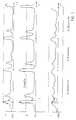
- FIG. 2shows, using an example with three Doppler channels, schematically the impulse responses of a 31-bit PN sequence in the three Doppler channels, with an assumed frequency offset from + 10 Hz to the receiver.
- Channel Bis the original channel (no frequency offset)
- channel Ais offset by + 50 Hz
- channel Cby - 50 Hz. It is assumed to spread on two paths with different amplitudes.
- Tis a bit length.
- the coarse frequency offset of the received signal with respect to the receiveris determined by the digital signal processor by selecting the Doppler channel with the greatest amplitude in the quadrature signal, in FIG. 2 channel B.
- the thresholdis to be determined by testing.
- the strongest signal values from this channelare then used to determine the exact frequency offset from the phase rotation from PN sequence to PN sequence. More on this is e.g. B. DE-C2-28 22 874.
- the Doppler channels of ⁇ 50 Hz detuningare generated in the low-pass channel (sine and cosine channel) using the Manske method (Manske, RA: Computer Simulation of Narrowband Systems. IEEE Trans. Comp. Vol. C-17, No 4 April, 1968, pp. 301-308).
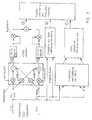
- FIG. 3shows a block diagram for three such Doppler channels. Only channel A is shown in detail.
- the shift procedure according to Manskeconsists of a crosswise connection of the sine and cosine channels in four multiplication and two addition operations. This part is omitted in channel B, in channel C the arrangement is the same as in A, with a negative ⁇ . All three channels each have two matched filters TF (-z).
- the output signals of the two matched filters of a Doppler channelmust be combined according to the quadrature method (squaring, adding) and analyzed using a pattern recognition process.
- a characteristic of this processis the fact that, according to the periodically repeated PN sequences, the quadrature output signals of the three Doppler channels must also be repeated every 31 bit step intervals. Only interference signals (e.g. channel noise) and ionospheric instability overlap this periodic process and falsify it.
- An advantageous pattern recognition processis based on recognizing a similarity of the signal intervals repeated every 31 steps. Another important property of the quadrature output signals is their amplitude increase compared to the received signal before the correlation (matched filtering).
- the security of the signal detectionis the higher, the more PN sequence repetitions occur in the preamble.
- the similarity of the quadrature signalcan be determined according to the invention both by comparing the amplitude of the successive 31-bit intervals and by cross-correlation processes. In order to take into account the interferences to be expected in practice, a slight deviation from the previous PN interval to the next 31-bit interval is permitted.
- the cross correlationis formed between a PN interval and the previous buffered PN interval.
- mean valuescan advantageously also be formed over a plurality of signal amplitudes (for a preamble of 10 PN sequences, e.g. over 5), in each case at intervals of 31 bits, and the mean similarity of these signal amplitudes can be assessed, stronger signal values being preferably weighted .
Landscapes
- Engineering & Computer Science (AREA)
- Computer Networks & Wireless Communication (AREA)
- Signal Processing (AREA)
- Radar Systems Or Details Thereof (AREA)
- Digital Transmission Methods That Use Modulated Carrier Waves (AREA)
Abstract
Description
Translated fromGermanDie Erfindung betrifft ein Verfahren zur Erkennung der Frequenzlage bei digitalen Nachrichtenübertragungen nach dem Oberbegriff des Anspruchs 1, wie es aus der DE-C2-28 22 874 bekannt ist.The invention relates to a method for detecting the frequency position in digital message transmissions according to the preamble of claim 1, as is known from DE-C2-28 22 874.
Das bekannte Verfahren wird insbesondere eingesetzt für die serielle Schnelltelegraphie im Kurzwellenbereich. Auf dem Übertragungsweg erfolgen starke lineare Verzerrungen, Phasendrehungen und Frequenzversätze der Signale. Das Empfangssignal ist meist ein Gemisch aus mehreren "Echos". Daher müssen im Empfänger alle diese Effekte erkannt und zur Entzerrung des Signals benutzt werden. Das bekannte Verfahren benutzt als Präambel der einzelnen Datenblöcke eine mehrfach wiederholte PN-Folge (PN = Pseudo Noise, also Pseudo-Rauschfolge), von vorzugsweise 31 Bit Länge. Die Präambel wird empfangsseitig mittels Transversalfiltern im Quadraturverfahren komprimiert. Präambel und Datenblöcke werden getrennt verarbeitet, und zwar werden aus der Untersuchung der Präambel Filtereinstellungen gewonnen, die im Datenpfad zur Echo-Entzerrung benutzt werden.The known method is used in particular for high-speed serial telegraphy in the shortwave range. Strong linear distortions, phase shifts and frequency offsets of the signals occur on the transmission path. The received signal is usually a mixture of several "echoes". All of these effects must therefore be recognized in the receiver and used to equalize the signal. The known As a preamble to the individual data blocks, the method uses a repeatedly repeated PN sequence (PN = pseudo noise, that is, a pseudo noise sequence), preferably 31 bits in length. The preamble is compressed on the receiving side by means of transverse filters using the quadrature method. Preamble and data blocks are processed separately, namely filter settings are obtained from the examination of the preamble, which are used in the data path for echo equalization.
FIG. 1 zeigt die bekannte Anordnung zur (Quadratur"-)Demodulation des übertragenen geträgerten Signals auf der Empfangsseite. Die Anordnung entspricht derjenigen eines kohärenten Empfängers. Die Entzerrung erfolgt im Basisband. Für die "Quadratur"-Demodulation sind zwei Kanäle - ein Sinus- und ein Cosinuskanal - erforderlich, in denen das linear verzerrte geträgerte Empfangssignal mit einem von einem Überlagerungsoszillator bereitgestellten Trägersignal in einem Fall direkt und im anderen Fall nach einer Phasenverschiebung des Trägers um 90° multiplikativ gemischt wird. Da also zwei Kanäle (der Sinus- und der Cosinuskanal) im Echoentzerrer-Prozessor verarbeitet werden müssen, ist auch die Impulsantwort in beiden Kanälen zu bestimmen. Um die gesamte in einem Kanal vorhandene Energie des Nutzsignals nutzen zu können, ist im Sinus- und im Cosinuskanal ein zum jeweiligen Kanal zeitinverses Filter, ein sogenanntes Matched-Filter M. F., enthalten, das als Transversalfilteranordnung ausgebildet ist. Die Gewichte der Transversalfilter entsprechen der zeitinversen Impulsantwort der beiden Kanäle. Durch diese Matched-Filter wird eine nichtlineare Quadrierung vermieden (das Verfahren soll ja linear sein). Die Transversalfilterausgänge im Matched-Filter werden mittels Addierer so zusammengeschaltet, daß zwei Ausgangssignale entstehen, die einem reziproken Filter R. F. zugeführt werden (Quadratur-Tiefpaß-Entzerrer). Am Ausgang des reziproken Filters stehen die entzerrten Daten zur Verfügung.FIG. 1 shows the known arrangement for (quadrature ") demodulation of the transmitted carried signal on the receiving side. The arrangement corresponds to that of a coherent receiver. The equalization takes place in the baseband. For" quadrature "demodulation, there are two channels - a sine and a Cosine channel - required, in which the linearly distorted received signal is mixed with a carrier signal provided by a local oscillator in one case directly and in the other case after a phase shift of the carrier by 90 ° multiplicatively, so since two channels (the sine and the cosine channel) The impulse response in both channels must also be determined in the echo equalizer processor. To be able to use the entire energy of the useful signal present in one channel, a filter that is inverse in time to the respective channel, a so-called matched signal, must be used in the sine and cosine channels. Filter MF, included, which as a transversal filter arrangement au The weights of the transversal filters correspond to the inverse time response of the two channels. These matched filters avoid nonlinear squaring (the method should be linear). The transversal filter outputs in the matched filter are interconnected by means of adders, that two output signals arise, which are fed to a reciprocal filter RF (quadrature low-pass equalizer). The equalized data is available at the output of the reciprocal filter.
Anstelle der hier verwendeten Zweiseitenbandmodulation kann auch die Restseitenbandmodulation verwendet werden. Bei diesem Modulationsverfahren kann die Auswertung der Signale im reziproken Filter auf das Ausgangssignal des Cosinus-Zweiges des Matched-Filters, d.h. auf den Realteil des komplexen Signals beschränkt werden.Instead of the double sideband modulation used here, the residual sideband modulation can also be used. With this modulation method, the evaluation of the signals in the reciprocal filter can be based on the output signal of the cosine branch of the matched filter, i.e. be limited to the real part of the complex signal.
Die Transversalfilteranordnung im Matched-Filter kann für diesen Fall entsprechend vereinfacht werden.The transversal filter arrangement in the matched filter can be simplified accordingly in this case.
Die Frequenz-Differenz (Frequenzablage) zwischen Empfangssignal und Empfänger kann bis zu 60 Hz erreichen, da die Frequenznormal-Genauigkeit in einfachen Sende- und Empfangsgeräten bei etwa 10⁻⁶ liegt und der Frequenzbereich bis 30 MHz reicht.The frequency difference (frequency offset) between the received signal and the receiver can reach up to 60 Hz, since the frequency standard accuracy in simple transmitters and receivers is around 10⁻⁶ and the frequency range extends to 30 MHz.
Bei 3 000 Bd Schrittgeschwindigkeit dauert eine 31 Bit PN-Folge TPN = 31/VT = 10,3 msec, wobei TPN die Dauer der PN-Folge und VT die Schrittgeschwindigkeit (Baudrate) ist. Mit einfachen Korrelationstechniken, das ist Impulskompression mit Hilfe eines Transversalfilters, dessen Gewichte (+und -Einsen) zur PN-Folge zeitinvers sind (Matched-Filter im Zeitbereich, Sinus- und Cosinuskanal), kommt man mit einer Frequenzdifferenz zurecht, die einer 90°-Drehung für die Folgelänge entspricht. Bei 10 msec sind das etwa 25 Hz. Ist die Frequenzdifferenz höher, kommt es wegen der sogenannten Ambiguity-Funktion zu erheblicher Reduktion der Kompressions-Überhöhung am Ausgang des Korrelationsfilters.At 3,000 Bd step speed, a 31 bit PN sequence TPN = 31 / VT = 10.3 msec, where TPN is the duration of the PN sequence and VT is the step speed (baud rate). With simple correlation techniques, i.e. pulse compression with the help of a transversal filter, the weights (+ and -ins) of which are inverse in time to the PN sequence (matched filter in the time domain, sine and cosine channel), one can cope with a frequency difference that is 90 ° -Turn for the following length corresponds. At 10 msec, this is about 25 Hz. If the frequency difference is higher, the so-called ambiguity function leads to a significant increase Reduction of the compression increase at the output of the correlation filter.
Aufgabe der Erfindung ist es, ein Verfahren der eingangs genannten Art anzugeben, welches auf einfache Weise eine Erkennung der groben Frequenzablage ermöglicht.The object of the invention is to provide a method of the type mentioned at the outset which enables the rough frequency offset to be identified in a simple manner.
Die Lösung dieser Aufgabe ist im kennzeichnenden Teil des Patentanspruchs 1 beschrieben. Die weiteren Ansprüche beinhalten vorteilhafte Weiterbildungen und Ausführungsarten des erfindungsgemäßen Verfahrens.The solution to this problem is described in the characterizing part of patent claim 1. The further claims contain advantageous developments and embodiments of the method according to the invention.
Ein Verfahren zur Erkennung der Frequenzablage bei digitalen Nachrichtenübertragungen mit Echoausbreitung, insbesondere im Kurzwellenbereich, bei welchem jeder Datenblock eine Präambel aus einer mehrfach wiederholten PN-Folge enthält, die empfangsseitig mittels Transversalfilter komprimiert wird, deren Gewichte entsprechend den Bitwerten der zeitinversen vollständigen PN-Folge gewählt sind, wird nach der Erfindung dahingehend verbessert:
- daß die Präambel empfangsseitig mehreren simultanen Dopplerkanälen zugeführt wird, von denen ein erster Dopplerkanal gegenüber der Empfangsfrequenz nicht frequenzversetzt ist und die übrigen Dopplerkanäle paarweise gegenüber der Empfangsfrequenz um einen positiven bzw. negativen Betrag frequenzversetzt sind,
- daß die Präambel in allen Dopplerkanälen mittels der Transversalfilter komprimiert wird und in ein Quadratursignal zusammengefaßt wird, und
- daß zur Bestimmung der Frequenzablage der Dopplerkanal mit den größten Amplituden im Quadratursignal ausgewählt wird.
- that the preamble is supplied to several simultaneous Doppler channels at the receiving end, of which a first Doppler channel is not frequency-shifted with respect to the reception frequency and the other Doppler channels are frequency-shifted in pairs with respect to the reception frequency by a positive or negative amount,
- that the preamble in all Doppler channels is compressed by means of the transversal filter and combined into a quadrature signal, and
- that the Doppler channel with the largest amplitudes in the quadrature signal is selected to determine the frequency offset.
Ein wesentlicher Vorteil dieser Lösung besteht darin, daß die grobe Frequenzablage der übertragenen digitalen Signale sehr einfach und sehr schnell erkannt werden kann.A major advantage of this solution is that the rough frequency offset of the transmitted digital signals can be recognized very easily and very quickly.
In einer vorteilhaften Weiterbildung des erfindungsgemäßen Verfahrens ist vorgesehen, daß die größten Amplituden im Quadratursignal erst nach einer Mittelwertbildung der maximal erwarteten Kanalstoßantwortdauer bestimmt werden.In an advantageous development of the method according to the invention, it is provided that the greatest amplitudes in the quadrature signal are only determined after averaging of the maximum expected channel impulse response duration.
Mit dieser Maßnahme wird die Quote der richtig erkannten Signale bei der Signalerkennung erheblich erhöht.With this measure, the quota of correctly recognized signals during signal recognition is considerably increased.
Besonders gute Ergebnisse bei der Signalerkennung werden erzielt, wenn der Frequenzversatz Δf zwischen den Dopplerkanälen gleich oder zumindest im wesentlichen gleich ist dem Inversen der doppelten PN-Folge-Dauer TPN und vorzugsweise etwa ± 50 Hz beträgt.Particularly good results in signal detection are achieved if the frequency offset Δf between the Doppler channels is the same or at least substantially the same as the inverse of the double PN sequence duration TPN and is preferably approximately ± 50 Hz.
Zur genaueren Bestimmung der Frequenzablage mittels der Phasendrehung von PN-Folge zu PN-Folge werden zweckmäßigerweise die stärksten Kompressions-Signalwerte im Dopplerkanal mit den größten Amplituden herangezogen.To determine the frequency offset more precisely by means of the phase rotation from PN sequence to PN sequence, the strongest compression signal values in the Doppler channel with the greatest amplitudes are expediently used.
Zur Mustererkennung der komprimierten Präambel werden vorteilhafterweise die Quadratursignale auf Ähnlichkeit von PN-Intervall zu PN-Intervall untersucht.For pattern recognition of the compressed preamble, the quadrature signals are advantageously examined for similarity between the PN interval and the PN interval.
Die Untersuchung auf Ähnlichkeit kann dabei z.B. durch Kreuzkorrelation zwischen einem PN-Intervall und dem vorangegangenen zwischengespeicherten PN-Intervall oder durch Amplitudenvergleiche zwischen den aufeinanderfolgenden PN-Intervallen erfolgen, wobei im letzteren Fall zweckmäßigerweise Mittelwerte über mehrere Signalamplituden jeweils im Abstand der PN-Intervalle gebildet werden und die mittlere Ähnlichkeit dieser Mittelwerte bewertet wird.The examination for similarity can be done, for example, by cross-correlation between a PN interval and the previous buffered PN interval or by comparing the amplitudes between the successive PN intervals, in the latter case expediently forming mean values over a plurality of signal amplitudes each at intervals of the PN intervals and evaluating the mean similarity of these mean values.
Die Erfindung wird im folgenden anhand der FIG. 2 und 3 näher erläutert.The invention is described below with reference to FIG. 2 and 3 explained in more detail.
Die heute zur Verfügung stehenden Rechenleistungen von digitalen Signalprozessoren (DSP) erreicht 10 Millionen Instruktionen/Operationen pro Sekunde bei einem single chip Prozessor. Das ist in Ausführung des erfindungsgemäßen Verfahrens für eine Echtzeitverarbeitung in mehreren frequenzversetzten, simultanen Dopplerkanälen ausreichend. Diese simultanen Dopplerkanäle erhalten vorzugsweise einen Frequenzabstand Δf von jenem doppelten Wert, der der 90°-Drehung entspricht (Δf=1/2TPN). Somit sind es bei 3 000 Bd zweimal 25 Hz, also 50 Hz. Mit beispielsweise insgesamt drei solcher Dopplerkanälen erzielt man einen eindeutigen Signal-Erkennungs- und Meßbereich von theoretisch immerhin plus/minus 3 x 25 Hz, also 75 Hz. In jedem der Dopplerkanäle werden die empfangenen Signale korreliert, und zwar simultan, also insgesamt sechs Matched-Filter zur PN-Folge erzeugt. Die beiden Ausgangssignale der Korrelatoren jedes Dopplerkanals werden anschließend quadriert und addiert (Quadratursignal).The computing power of digital signal processors (DSP) available today reaches 10 million instructions / operations per second with a single chip processor. In executing the method according to the invention, this is sufficient for real-time processing in a plurality of frequency-offset, simultaneous Doppler channels. These simultaneous Doppler channels are preferably given a frequency spacing Δf of twice the value which corresponds to the 90 ° rotation (Δf = 1 / 2TPN ). So at 3,000 Bd it is twice 25 Hz, i.e. 50 Hz. With a total of three such Doppler channels, for example, a clear signal detection and measurement range of theoretically plus / minus 3 x 25 Hz, i.e. 75 Hz, is achieved. In each of the Doppler channels the received signals are correlated, namely simultaneously, i.e. a total of six matched filters are generated for the PN sequence. The two output signals of the correlators of each Doppler channel are then squared and added (quadrature signal).
FIG. 2 zeigt anhand eines Beispiels mit drei Dopplerkanälen schematisch die Impulsantworten einer 31-Bit PN-Folge in den drei Dopplerkanälen, bei einer angenommenen Frequenzablage von + 10 Hz zum Empfänger. Kanal B ist der Originalkanal (kein Frequenzversatz), Kanal A ist dagegen um + 50 Hz, Kanal C um - 50 Hz frequenzversetzt. Es ist eine Ausbreitung auf zwei Pfaden mit unterschiedlicher Amplitude angenommen. Mit T ist eine Bitlänge bezeichnet. Die grobe Frequenzablage des Empfangssignal gegenüber dem Empfänger bestimmt der digitale Signalprozessor durch Auswahl des Dopplerkanals mit der größten Amplitude im Quadratursignal, in FIG. 2 also den Kanal B. Die Schwelle ist durch Erprobung festzulegen.FIG. 2 shows, using an example with three Doppler channels, schematically the impulse responses of a 31-bit PN sequence in the three Doppler channels, with an assumed frequency offset from + 10 Hz to the receiver. Channel B is the original channel (no frequency offset), channel A, however, is offset by + 50 Hz, channel C by - 50 Hz. It is assumed to spread on two paths with different amplitudes. T is a bit length. The coarse frequency offset of the received signal with respect to the receiver is determined by the digital signal processor by selecting the Doppler channel with the greatest amplitude in the quadrature signal, in FIG. 2 channel B. The threshold is to be determined by testing.
Aus diesem Kanal werden dann die stärksten Signalwerte herangezogen zur Bestimmung der genauen Frequenzablage aus der Phasendrehung von PN-Folge zu PN-Folge. Näheres dazu ist z. B. der DE-C2-28 22 874 zu entnehmen.The strongest signal values from this channel are then used to determine the exact frequency offset from the phase rotation from PN sequence to PN sequence. More on this is e.g. B. DE-C2-28 22 874.
Die Dopplerkanäle von ± 50 Hz Verstimmung erzeugt man im Tiefpaß-Kanal (Sinus- und Cosinuskanal) mit der Methode von Manske (Manske, R.A.: Computer Simulation of Narrowband Systems. IEEE Trans. Comp. Vol. C-17, No 4 April, 1968, S.301-308).The Doppler channels of ± 50 Hz detuning are generated in the low-pass channel (sine and cosine channel) using the Manske method (Manske, RA: Computer Simulation of Narrowband Systems. IEEE Trans. Comp. Vol. C-17, No 4 April, 1968, pp. 301-308).
FIG. 3 zeigt ein Blockschaltbild für drei derartige Dopplerkanäle. Es ist nur Kanal A ausführlich dargestellt. Die Verschiebungsprozedur nach Manske besteht in einer kreuzweisen Verknüpfung von Sinus- und Cosinus-Kanal in vier Multiplikations- und zwei Additionsoperationen. In Kanal B entfällt dieser Teil, in Kanal C ist die Anordnung entsprechend wie in A, mit negativem Δω. Alle drei Kanäle weisen jeweils zwei Matched-Filter TF (-z) auf.FIG. 3 shows a block diagram for three such Doppler channels. Only channel A is shown in detail. The shift procedure according to Manske consists of a crosswise connection of the sine and cosine channels in four multiplication and two addition operations. This part is omitted in channel B, in channel C the arrangement is the same as in A, with a negative Δω. All three channels each have two matched filters TF (-z).
Der Artikel von R. ESPRESTER. "Testfolgen zur Bestimmung der Kanalantwort bei Funkübertragung", erschienen im Mikrowellenmagazin Nr.5 (1988), beschreibt ein komprimierendes Digitalfilter in Zeitinverser Anordnung (matched filter).The article by R. ESPRESTER. "Test sequences for determining the channel response in radio transmission", published in microwave magazine No. 5 (1988), describes a compressing digital filter in a time inverse arrangement (matched filter).
Die Ausgangssignale der beiden Matched-Filter eines Dopplerkanals müssen entsprechend dem Quadraturverfahren (Quadrieren, Addieren) zusammengefaßt und mit Hilfe eines Mustererkennungsprozesses analysiert werden. Charakteristisch für diesen Prozeß ist die Tatsache, daß sich entsprechend den periodisch wiederholten PN-Folgen die Quadraturausgangssignale der drei Dopplerkanäle ebenfalls alle 31 Bit-Schritt-Intervalle wiederholen müssen. Einzig Störungssignale (z. B. Kanalgeräusch) und ionosphärische Instabilität überlagern sich diesem periodischen Vorgang und verfälschen diesen.The output signals of the two matched filters of a Doppler channel must be combined according to the quadrature method (squaring, adding) and analyzed using a pattern recognition process. A characteristic of this process is the fact that, according to the periodically repeated PN sequences, the quadrature output signals of the three Doppler channels must also be repeated every 31 bit step intervals. Only interference signals (e.g. channel noise) and ionospheric instability overlap this periodic process and falsify it.
Ein vorteilhafter Muster-Erkennungsprozeß gemäß der Erfindung ist darauf abgestellt, eine Ähnlichkeit der alle 31 Schritte wiederholten Signalintervalle zu erkennen. Eine weitere wichtige Eigenschaft der Quadraturausgangssignale ist deren Amplituden-Überhöhung im Vergleich zum Empfangssignal vor der Korrelation (Matched-Filterung).An advantageous pattern recognition process according to the invention is based on recognizing a similarity of the signal intervals repeated every 31 steps. Another important property of the quadrature output signals is their amplitude increase compared to the received signal before the correlation (matched filtering).
Die Sicherheit der Signalerkennung ist umso höher, je mehr PN-Folgen-Wiederholungen in der Präambel vorkommen. Die Ähnlichkeit des Quadratursignals kann erfindungsgemäß sowohl durch Amplitudenvergleich der aufeinanderfolgenden 31er-Bit-Intervalle als auch durch Kreuzkorrelationsprozesse ermittelt werden. Um die in praxi zu erwartenden Störeinflüsse zu berücksichtigen, läßt man eine geringe Abweichung vom vorausgehenden PN-Intervall zum nächsten 31-Bit-Intervall zu.The security of the signal detection is the higher, the more PN sequence repetitions occur in the preamble. The similarity of the quadrature signal can be determined according to the invention both by comparing the amplitude of the successive 31-bit intervals and by cross-correlation processes. In order to take into account the interferences to be expected in practice, a slight deviation from the previous PN interval to the next 31-bit interval is permitted.
Die Kreuzkorrelation wird zwischen einem PN-Intervall und dem vorausgegangenen zwischengespeicherten PN-Intervall gebildet.The cross correlation is formed between a PN interval and the previous buffered PN interval.
Beim Amplitudenvergleich können vorteilhafterweise auch Mittelwerte über mehrere (bei einer Präambel von 10 PN-Folgen z. B. über 5) Signalamplituden gebildet werden, jeweils im Abstand von 31 Bit, und die mittlere Ähnlichkeit dieser Signalamplituden bewertet werden, wobei stärkere Signalwerte bevorzugt gewichtet werden.When comparing amplitudes, mean values can advantageously also be formed over a plurality of signal amplitudes (for a preamble of 10 PN sequences, e.g. over 5), in each case at intervals of 31 bits, and the mean similarity of these signal amplitudes can be assessed, stronger signal values being preferably weighted .
Claims (9)
- Method for the recognition of the frequency deviation in digital communications transmissions with echo propagation, in particular in the shortwave range, in which each data block contains a preamble of a pseudo-noise sequence which is repeated several times and compressed at the receiving end by means of parallel filters, the weights of which are chosen in accordance with the bit values of the time-inverse complete pseudo-noise sequence, characterised thereby,- that the preamble is fed at the receiving end to several simultaneous Doppler channels, of which a first Doppler channel is not shifted in frequency relative to the received frequency and the remaining Doppler channels are shifted in frequency relative to the received frequency in pairs of one by a positive and one by a negative amount (Δf),- that the preamble is compressed in all Doppler channels by means of the parallel filters and- that the Doppler channel with the greatest amplitudes in the quadrature signal is chosen for ascertaining the frequency deviation.
- Method according to claim 1, characterised thereby, that altogether three simultaneous Doppler channels are provided at the receiving end, of which two are shifted in frequency relative to the received frequency by the same positive or negative amount (Δf).
- Method according to one of the claims 1 and 2, characterised thereby, that the greatest amplitudes in the quadrature signal are ascertained only after a mean value formation over a time interval corresponding with the maximum expected channel pulse response duration.
- Method according to one of the preceding claims, characterised thereby, that the frequency shift (Δf) between the Doppler channels is equal or at least substantially equal to the inverse of twice the pseudo-noise sequence duration TpN.
- Method according to one of the preceding claims, characterised thereby, that the strongest compression signal values in the Doppler channel with the greatest amplitudes are drawn upon for the more exact ascertaining of the frequency shift by means of the phase rotation from pseudo-noise sequence to pseudo-noise sequence.
- Method according to one of the preceding claims, characterised thereby, that the quadrature signals are examined for similarity from pseudo-noise sequence to pseudo-noise sequence for the recognition of a pattern in the compressed preambles.
- Method according to claim 6, characterised thereby, that the examination for similarity takes place through crosscorrelation between one pseudo-noise interval and the preceding intermediately stored pseudo-noise interval.
- Method according to claim 6, characterised thereby, that the examination for similarity takes place by amplitude comparisons between the successive pseudo-noise intervals.
- Method according to claim 8, characterised thereby, that mean values are formed over several signal amplitudes each time at the spacing of the pseudo-noise intervals and that the mean similarity of these mean values is evaluated.
Applications Claiming Priority (5)
| Application Number | Priority Date | Filing Date | Title |
|---|---|---|---|
| DE4028369 | 1990-09-07 | ||
| DE4028369 | 1990-09-07 | ||
| DE4127501ADE4127501A1 (en) | 1990-09-07 | 1991-08-20 | METHOD FOR DETECTING THE FREQUENCY STORAGE IN DIGITAL MESSAGE TRANSMISSIONS |
| DE4127501 | 1991-08-20 | ||
| PCT/EP1991/001661WO1992004783A1 (en) | 1990-09-07 | 1991-09-03 | Method of determining the frequency deviation in digital communications transmissions |
Publications (2)
| Publication Number | Publication Date |
|---|---|
| EP0500846A1 EP0500846A1 (en) | 1992-09-02 |
| EP0500846B1true EP0500846B1 (en) | 1995-06-28 |
Family
ID=25896638
Family Applications (1)
| Application Number | Title | Priority Date | Filing Date |
|---|---|---|---|
| EP91914965AExpired - LifetimeEP0500846B1 (en) | 1990-09-07 | 1991-09-03 | Method of determining the frequency deviation in digital communications transmissions |
Country Status (4)
| Country | Link |
|---|---|
| US (1) | US5305347A (en) |
| EP (1) | EP0500846B1 (en) |
| DE (2) | DE4127501A1 (en) |
| WO (1) | WO1992004783A1 (en) |
Families Citing this family (23)
| Publication number | Priority date | Publication date | Assignee | Title |
|---|---|---|---|---|
| WO1994008251A1 (en)* | 1992-10-01 | 1994-04-14 | Sodena | Device for the acquisition and compression of pulse trains |
| KR950004878B1 (en)* | 1992-12-29 | 1995-05-15 | 재단법인 한국전자통신연구소 | Micro Frequency Shift Detection Method |
| JP3301555B2 (en)* | 1993-03-30 | 2002-07-15 | ソニー株式会社 | Wireless receiver |
| DE69416404T2 (en)* | 1993-06-07 | 1999-06-10 | Martin Communications Pty. Ltd., Mount Waverley, Victoria | FADINGS SIMULATOR |
| JP2938337B2 (en)* | 1994-03-09 | 1999-08-23 | 三菱電機株式会社 | Data demodulation circuit for spread spectrum communication |
| US6128331A (en)* | 1994-11-07 | 2000-10-03 | Cisco Systems, Inc. | Correlation system for use in wireless direct sequence spread spectrum systems |
| US5784402A (en)* | 1995-01-09 | 1998-07-21 | Kamilo Feher | FMOD transceivers including continuous and burst operated TDMA, FDMA, spread spectrum CDMA, WCDMA and CSMA |
| GB2309868A (en)* | 1996-01-30 | 1997-08-06 | Sony Corp | Radio receiver detects FCCH synchronising signal |
| US6226336B1 (en)* | 1998-02-20 | 2001-05-01 | Telefonaktiebolaget Lm Ericsson (Publ) | Method and apparatus for detecting a frequency synchronization signal |
| JP2933080B1 (en)* | 1998-04-24 | 1999-08-09 | 日本電気株式会社 | Reception synchronizer using chirp signal |
| US6356608B1 (en) | 1998-06-29 | 2002-03-12 | Telefonaktiebolaget Lm Ericsson (Publ) | Method, apparatus, and system for determining a location of a frequency synchronization signal |
| DE19934660C2 (en) | 1998-09-02 | 2000-08-31 | Daimler Chrysler Ag | Multi-frequency superposition receiver |
| US6366762B1 (en)* | 1999-03-31 | 2002-04-02 | Qualcomm, Inc. | System and method for measuring round trip delay on the paging and access channels |
| US6556167B1 (en)* | 1999-05-28 | 2003-04-29 | Rockwell Collins, Inc. | Direct acquisition of very large PN sequences in GPS systems |
| EP1156589B1 (en)* | 2000-05-17 | 2008-01-09 | Sony Deutschland GmbH | AM receiver |
| US7742930B1 (en)* | 2000-07-06 | 2010-06-22 | Perot Systems Corporation | Web-based managed care system having a common administrative account |
| JP4282520B2 (en)* | 2004-03-24 | 2009-06-24 | シャープ株式会社 | Signal processing method, signal output device, signal processing device, image processing device, and image forming device |
| US7688878B2 (en)* | 2006-03-16 | 2010-03-30 | The Boeing Company | Method and device of peak detection in preamble synchronization for direct sequence spread spectrum communication |
| US9490867B2 (en) | 2011-08-16 | 2016-11-08 | Harris Corporation | CDMA communications device and related methods |
| RU2582202C1 (en)* | 2014-12-24 | 2016-04-20 | Федеральное государственное бюджетное образовательное учреждение высшего профессионального образования "Липецкий государственный технический университет" | Alternating current drive |
| US11729716B2 (en) | 2017-04-11 | 2023-08-15 | Mediatek, Inc. | Efficient preamble design and modulation schemes for wake-up packets in WLAN with wake-up radio receivers |
| CN111181885B (en)* | 2018-11-13 | 2022-09-09 | 中国科学院上海高等研究院 | Transmission method and reception method of preamble signal in ultra-high-speed mobile broadband communication |
| CN112152677B (en)* | 2019-06-28 | 2021-11-16 | 清华大学 | Space-based Opportunistic Signal Doppler Frequency Estimation Method, Apparatus, Equipment and Medium |
Family Cites Families (6)
| Publication number | Priority date | Publication date | Assignee | Title |
|---|---|---|---|---|
| US3694757A (en)* | 1970-05-04 | 1972-09-26 | Totuus Communications Inc | Pseudo-random code recognition receiver |
| DE2822874A1 (en)* | 1976-02-28 | 1979-11-29 | Licentia Gmbh | Single or two-sideband signal transmission with suppressed carrier - has each data block preceded by test pulse train containing complete pseudo-noise train |
| JPS60260222A (en)* | 1984-06-07 | 1985-12-23 | Nec Corp | Adaptive variable switched capacitor filter |
| GB2161344A (en)* | 1984-07-06 | 1986-01-08 | Philips Electronic Associated | Transmission of digital data |
| US5090023A (en)* | 1986-09-29 | 1992-02-18 | Kabushiki Kaisha Kenwood | Spread spectrum communication system |
| ES2046564T3 (en)* | 1989-03-16 | 1994-02-01 | Siemens Aktiengesellschaft | CIRCUIT FOR THE RECOGNITION OF A FREQUENCY REFERENCE SIGNAL. |
- 1991
- 1991-08-20DEDE4127501Apatent/DE4127501A1/ennot_activeWithdrawn
- 1991-09-03WOPCT/EP1991/001661patent/WO1992004783A1/enactiveIP Right Grant
- 1991-09-03EPEP91914965Apatent/EP0500846B1/ennot_activeExpired - Lifetime
- 1991-09-03USUS07/855,683patent/US5305347A/ennot_activeExpired - Fee Related
- 1991-09-03DEDE59105871Tpatent/DE59105871D1/ennot_activeExpired - Fee Related
Also Published As
| Publication number | Publication date |
|---|---|
| DE4127501A1 (en) | 1992-03-12 |
| US5305347A (en) | 1994-04-19 |
| EP0500846A1 (en) | 1992-09-02 |
| WO1992004783A1 (en) | 1992-03-19 |
| DE59105871D1 (en) | 1995-08-03 |
Similar Documents
| Publication | Publication Date | Title |
|---|---|---|
| EP0500846B1 (en) | Method of determining the frequency deviation in digital communications transmissions | |
| DE3834457C2 (en) | Spread spectrum receiver | |
| EP0428199B1 (en) | Receiver for digital communication system with channel estimator | |
| DE68923634T2 (en) | Equalizer for radio receivers. | |
| EP3143415B1 (en) | Method and measuring device for intermodulation measurement | |
| DE4006566C2 (en) | Distance measuring systems | |
| EP0454266B1 (en) | Receiver comprising a circuit for estimating frequency offset | |
| DE2800898A1 (en) | MESSAGE TRANSMISSION SYSTEM WORKING WITH EXPANDED FREQUENCY RANGE | |
| DE102014226073A1 (en) | Method and device for operating a radar system of a motor vehicle | |
| DE1466171B2 (en) | METHOD AND DEVICE FOR SEPARATION OF TIME-SHIFTED IDENTICAL SIGNALS | |
| DE69634466T2 (en) | Multi-User Reception for CDMA | |
| CH671124A5 (en) | ||
| DE69711247T2 (en) | INTERFERENCE CANCELLATION BY SIGNAL COMBINATION WITH A FREQUENCY CORRECTION | |
| DE3914214C1 (en) | Device for generating a pseudorandom noise signal | |
| DE19949586A1 (en) | System for analyzing an offset QPSK modulation can estimate the initial phase of an offset modulated signal by using a ZF signal converter and a frequency error compensator. | |
| DE4130863C2 (en) | Digital messaging system | |
| DE10027389A1 (en) | Synchronization method e.g. for signal receiver of global system for mobile (GSM) communication, involves comparing AM/FM demodulated signal with respective reference signals to detect time offset between them | |
| EP1169783A1 (en) | Signal identification in cdma-radio systems | |
| DE10347985B4 (en) | Method and apparatus for detecting transmit antenna diversity in the receiver and for scrambling code identification | |
| DE10300267B4 (en) | Demodulating a frequency modulated received signal by mapping the zero crossings to a sequence of parameter values | |
| DE19604676A1 (en) | Method for suppressing interference signals in a pulse Doppler radar | |
| DE4130865C2 (en) | Digital messaging system | |
| DE10122689C2 (en) | Method for channel estimation of a mobile radio channel and mobile radio receiver | |
| EP0932834A2 (en) | Method of determining receiver locations in a common wave network | |
| DE3240904C1 (en) | Message receiver has convolution unit that outputs fully correlated intermediate frequency signal of bit amplitude IF reference signal, message information bit exactly correlate and overlap |
Legal Events
| Date | Code | Title | Description |
|---|---|---|---|
| PUAI | Public reference made under article 153(3) epc to a published international application that has entered the european phase | Free format text:ORIGINAL CODE: 0009012 | |
| 17P | Request for examination filed | Effective date:19920505 | |
| AK | Designated contracting states | Kind code of ref document:A1 Designated state(s):DE FR GB | |
| RAP1 | Party data changed (applicant data changed or rights of an application transferred) | Owner name:TELEFUNKEN SYSTEMTECHNIK AG | |
| RAP1 | Party data changed (applicant data changed or rights of an application transferred) | Owner name:DEUTSCHE AEROSPACE AKTIENGESELLSCHAFT | |
| 17Q | First examination report despatched | Effective date:19940328 | |
| RAP1 | Party data changed (applicant data changed or rights of an application transferred) | Owner name:DAIMLER-BENZ AEROSPACE AKTIENGESELLSCHAFT | |
| GRAA | (expected) grant | Free format text:ORIGINAL CODE: 0009210 | |
| AK | Designated contracting states | Kind code of ref document:B1 Designated state(s):DE FR GB | |
| REF | Corresponds to: | Ref document number:59105871 Country of ref document:DE Date of ref document:19950803 | |
| GBT | Gb: translation of ep patent filed (gb section 77(6)(a)/1977) | Effective date:19950907 | |
| ET | Fr: translation filed | ||
| PLBE | No opposition filed within time limit | Free format text:ORIGINAL CODE: 0009261 | |
| STAA | Information on the status of an ep patent application or granted ep patent | Free format text:STATUS: NO OPPOSITION FILED WITHIN TIME LIMIT | |
| 26N | No opposition filed | ||
| PGFP | Annual fee paid to national office [announced via postgrant information from national office to epo] | Ref country code:GB Payment date:20010814 Year of fee payment:11 | |
| PGFP | Annual fee paid to national office [announced via postgrant information from national office to epo] | Ref country code:DE Payment date:20010903 Year of fee payment:11 | |
| PGFP | Annual fee paid to national office [announced via postgrant information from national office to epo] | Ref country code:FR Payment date:20010904 Year of fee payment:11 | |
| REG | Reference to a national code | Ref country code:GB Ref legal event code:IF02 | |
| PG25 | Lapsed in a contracting state [announced via postgrant information from national office to epo] | Ref country code:GB Free format text:LAPSE BECAUSE OF NON-PAYMENT OF DUE FEES Effective date:20020903 | |
| PG25 | Lapsed in a contracting state [announced via postgrant information from national office to epo] | Ref country code:DE Free format text:LAPSE BECAUSE OF NON-PAYMENT OF DUE FEES Effective date:20030401 | |
| GBPC | Gb: european patent ceased through non-payment of renewal fee | Effective date:20020903 | |
| PG25 | Lapsed in a contracting state [announced via postgrant information from national office to epo] | Ref country code:FR Free format text:LAPSE BECAUSE OF NON-PAYMENT OF DUE FEES Effective date:20030603 | |
| REG | Reference to a national code | Ref country code:FR Ref legal event code:ST |