EP0500146B1 - Arthroscopic surgical instrument - Google Patents
Arthroscopic surgical instrumentDownload PDFInfo
- Publication number
- EP0500146B1 EP0500146B1EP92107397AEP92107397AEP0500146B1EP 0500146 B1EP0500146 B1EP 0500146B1EP 92107397 AEP92107397 AEP 92107397AEP 92107397 AEP92107397 AEP 92107397AEP 0500146 B1EP0500146 B1EP 0500146B1
- Authority
- EP
- European Patent Office
- Prior art keywords
- cutting
- instrument
- tissue
- cutting edges
- aperture
- Prior art date
- Legal status (The legal status is an assumption and is not a legal conclusion. Google has not performed a legal analysis and makes no representation as to the accuracy of the status listed.)
- Expired - Lifetime
Links
- 210000001519tissueAnatomy0.000description67
- 238000010008shearingMethods0.000description8
- 230000009471actionEffects0.000description7
- 210000000845cartilageAnatomy0.000description6
- 230000003100immobilizing effectEffects0.000description5
- 238000000034methodMethods0.000description5
- 238000001356surgical procedureMethods0.000description5
- 210000000988bone and boneAnatomy0.000description4
- 208000014674injuryDiseases0.000description4
- 239000012634fragmentSubstances0.000description3
- 210000003127kneeAnatomy0.000description3
- 210000004872soft tissueAnatomy0.000description3
- 230000008733traumaEffects0.000description3
- 208000008558OsteophyteDiseases0.000description2
- 241000237503PectinidaeSpecies0.000description2
- 241000791420PlicaSpecies0.000description2
- 238000013459approachMethods0.000description2
- 230000008901benefitEffects0.000description2
- 238000010276constructionMethods0.000description2
- 239000000835fiberSubstances0.000description2
- 239000012530fluidSubstances0.000description2
- 238000009499grossingMethods0.000description2
- 230000002829reductive effectEffects0.000description2
- 230000003252repetitive effectEffects0.000description2
- 238000002271resectionMethods0.000description2
- 230000029764retrograde extensionEffects0.000description2
- 235000020637scallopNutrition0.000description2
- 210000002303tibiaAnatomy0.000description2
- 230000000007visual effectEffects0.000description2
- 206010002091AnaesthesiaDiseases0.000description1
- 208000027418Wounds and injuryDiseases0.000description1
- 230000037005anaesthesiaEffects0.000description1
- 210000001188articular cartilageAnatomy0.000description1
- 238000005452bendingMethods0.000description1
- 230000008859changeEffects0.000description1
- 238000004891communicationMethods0.000description1
- 230000006378damageEffects0.000description1
- 238000001804debridementMethods0.000description1
- 230000007423decreaseEffects0.000description1
- 230000003247decreasing effectEffects0.000description1
- 230000001419dependent effectEffects0.000description1
- 230000000694effectsEffects0.000description1
- 238000002695general anesthesiaMethods0.000description1
- 230000006872improvementEffects0.000description1
- 238000003780insertionMethods0.000description1
- 230000037431insertionEffects0.000description1
- 230000001788irregularEffects0.000description1
- 210000000629knee jointAnatomy0.000description1
- 230000005499meniscusEffects0.000description1
- 230000003287optical effectEffects0.000description1
- 230000036961partial effectEffects0.000description1
- 239000002245particleSubstances0.000description1
- 230000002441reversible effectEffects0.000description1
- 238000005096rolling processMethods0.000description1
- 238000007493shaping processMethods0.000description1
- 210000005222synovial tissueAnatomy0.000description1
- 210000001694thigh boneAnatomy0.000description1
- 210000000689upper legAnatomy0.000description1
- 238000004804windingMethods0.000description1
Images


Classifications
- A—HUMAN NECESSITIES
- A61—MEDICAL OR VETERINARY SCIENCE; HYGIENE
- A61B—DIAGNOSIS; SURGERY; IDENTIFICATION
- A61B17/00—Surgical instruments, devices or methods
- A61B17/32—Surgical cutting instruments
- A61B17/320016—Endoscopic cutting instruments, e.g. arthroscopes, resectoscopes
- A61B17/32002—Endoscopic cutting instruments, e.g. arthroscopes, resectoscopes with continuously rotating, oscillating or reciprocating cutting instruments
Definitions
- This inventionconcerns arthroscopic surgical instruments according to the preamble of claim 1.
- the parent application 87 119 235 of the present divisional applicationprovides an arthroscopic instrument capable of removal of a wide variety of tissues. This not only decreases the risk of inadvertent scuffing, etc., but also increases the speed of the procedure. This swiftness can avoid physician fatigue, minimize anesthesia time for the patient, and increase the number of procedures possible with a given operating room facility.
- the instrument of the parent applicationhas an outer stationary member is employed sized to enter the joint through a puncture opening.
- the outer memberhas at least one distal aperture at which the wall of the outer member defines a first, fixed blade surface terminating in a cutting edge.
- An internal movable member disposed within the outer member and adapted to be power driven,has a second cutting edge arranged to move toward and closely past the fixed cutting edge in rapid, repetitive fashion to severe tissue.
- the movable memberhas an associated drive means which repeatedly moves the second cutting edge in this cutting direction.
- An improvement in the instrument of the parent applicationlies in the provision of a table extension at the aperture, projecting outwardly from the general contour of the body of the outer stationary member, the extension constructed and arranged to engage tissue against which the operator urges the instrument, in a manner to improve the repetitive cutting action.
- the table extensionprojects in retrograde manner with an outward component and a component of projection in the direction opposite to the direction of cutting movement of the inner member.
- the present inventionhas the object to improve the efficiency of power driven surgical instruments, particularly in case of high stresses associated with the shearing of thick tissue.
- An arthroscopic surgical instrumentas defined in claim 1.
- An arthroscopic instrument according to the inventioncomprises an outer stationary member sized to enter a joint to a puncture opening and having a distal aperture, the wall of said outer member and said aperture defining a first, fixed cutting edge, an internal moveable member disposed within said outer member, and having at least a pair of second cutting edges arranged to severe tissue and adapted to be power driven for repeated rapid movement of the second cutting edges.
- Said pair of second cutting edgesis arranged to move sequentially towered and closely past said first cutting edge, each second cutting edge defining one or more cutting points arranged longitudinally along said second cutting edge, and a cutting point of one of said second cutting edges being offset longitudinally from a cutting point of the next following second cutting edge, whereby said sequential second cutting edges have different cutting patterns.
- the US-A-4 598 710shows a surgical instrument with a fixed first cutting edge and a pair of moving second cutting edges.
- the cutting action of both second edgesstarts simultaneously toward fixed edges of different geometrical orientation, while according to the invention the cutting action of the second cutting edges starts sequentially toward the same fixed edge as a number of cutting points which are offset longitudinally.
- the outer member at opposite sides of the aperturedefines a pair of first, fixed cutting edges, the movable member adapted to move selectively in opposite directions and defining pairs of second cutting edges, each pair of second cutting edges adapted to coact with a respective first cutting edge; and, due to asymmetric arrangement of the cutting points, the body of the inner member, in the area of the second cutting edges, is of substantially uniform axial section.
- an instrumentcapable, in a majority of instances, of performing an entire arthroscopic surgical procedure, including, e.g., articular cartilage debridement, synovial resection, removal of osteophytes, plica resections and meniscectomies, normally performed in the past only by use of multiple instruments, with attendant increase in time, trauma, and risk of injury to healthy tissue in the joint.
- the powered arthoscopic surgical instrument 10consists of an outer stationary member 12, sized for introduction into a joint of the body via a puncture opening through the flesh, and a rotatable inner member 14 coaxial with the outer member and defining a distal shearing element 16 exposed through a distal opening 18 in the side and end surfaces of the outer member.
- table extensions 20Disposed along each side edge of the aperture 18 are table extensions 20, seen most clearly in Figs. 1 and 2, which project outwardly from the body of the outer stationary member, defining retrograde table surfaces 22 that extend beyond a blade surface 23 provided by the projection of thickness, T, of the wall of the outer member, and forming a generally concave opening into the instrument.
- the proximal end of instrument 10is received in powered handpiece 24, e.g., a component of the Universal Surgical System sold by Dyonics, Inc. of Andover, Massachusetts, as described by Sjostrom et al. in EP-A-189807, which is incorporated herein by reference.
- the handpiece 24is connected proximally to a source of suction 26, which draws a vacuum through a conduit defined through the handpiece 24 and instrument 10, to aperture 18.
- the apertureprovides communication between the interior conduit defined through the instrument and handpiece, and the environment about distal end of the instrument, the vacuum created by suction source 26 within the conduit tending to draw uncut tissues into aperture 18, and also evacuating, e.g., particles of tissue removed by instrument 10, as described below.
- rotatable inner member 14is associated with a reversible rotational drive motor disposed within handpiece 24.
- a controller/power source 28, connected via cable 30,powers the drive motor in handpiece 14 at a maximum rate of up to about 1400 rpm, and foot control 32 allows the surgeon to actuate the instrument to rotate in either direction, with his foot, leaving his hands free.
- the tubular, outer stationary member 12includes a first, generally cylindrical proximal portion 36 of substantially uniform outer diameter, D1, e.g., 5.5 mm, or, for use in the region of the posterior horn of the meniscus, 4.0 mm.
- a frustoconical portion 38having a decreasing outer diameter in the distal direction, to diameter, D2, of the distal segment 40 of the instrument, which, being less than diameter, D1, facilitates manuveuring and positioning of the distal end of the instrument within the confines of a joint.
- Removal of tissue from within the jointis further facilitated by a flattening of the surface of the outer member immediately proximal of the aperture 18 to form a flat, sloping surface 42 that, in combination with the end surface opening defined by the crescent shape distal end surface 44 defining distal end cutting edge 45 (Fig. 6), improves access of the cutting aperture of the instrument to tissue to be cut, as will be described below.
- the inner surface of the outer member 12 at aperture 18defines a pair of axially-extending first, fixed cutting edges 46 at opposite sides of the aperture 18, adapted to coact with the cutting edges of cutting element 16 of rotatable inner member 14, which we describe below with reference to Figs. 7-9.
- Table extensions 20, defining retrograde table extension surfaces 22,project generally outwardly from the body of the outer member 12 from the blade surfaces 23 at the first, fixed cutting edges 46, as best seen in Figs. 1 and 10, by a distance, S, which is at least 20% of the thickness, T, of the sidewall of the outer member.
- the extension and blade surfaces at the sides of the aperturein combination, define a substantially concave opening to aperture 18.
- each table extension 20there is defined a notch 47 in the region of the intersection of the outer member 12 and the proximal ends of the extensions, the purpose of which will be described below.
- table extensions 20serve to increase the size of the tissue-receiving window offered by the instrument, as the extensions act to capture and immobilize tissue in the area of the coacting cutting edges 46, 66 for enhanced cutting of a variety of character of tissue encountered, e.g., in the knee.
- the table extension 20extends outwardly beyond a projection, Y, of the outer surface 25 of the outer member 12, preferably by a distance, S, measured along a radius, R, about the axis of rotation, X, of the inner member, drawn through the first cutting edge 46.
- each table extension 20extends outwardly to terminate in a distal surface 27 lying at or beyond a line, D, projected tangent to the path of the second cutting edge 66 of inner member 14 at its midpoint, E, between the first cutting edges 46.
- Each table extension 20has an outer surface 29 which is a continuation of the outer surface 25 of the outer member 12.
- the outer surfaces 29lie on, or within, parallel planes F1, F2, projected tangent to the opposite sides of the outer member, whereby the critical diameter, D2, of the surgical instrument is not increased by the table extensions, and the instrument may be introduced into the narrow space between the femoral condyl and the tibial plateau, as described below with reference to Fig. 11.
- the rotatable cutter element 14is a tube having a partially closed end, with an asymmetrical cutting arrangement defined in a distal region 16.
- Cutting edges 48, 50are defined about openings 52, 54 on opposite sides of the inner element and extend into the distal end surface 56.
- Each cutting edgeconsists of a proximal, first circular opening portion 58, 59, formed, e.g., with ball cutters, through the side wall of the tubular inner element 14, generally into its interior, and a distal second, semicircular opening portion 60, 61, in the side wall of the inner element, and extending hemispherically into the end wall 56 of the element.
- the radii of the respective distal openingsextend proximally to overlap the adjacent respective proximal openings, and extend distally, beyond the end surface of the cutting element.
- the axes (A p , A p ', A D , A D ') of the pairs of proximal and distal opening portionsare longitudinally staggered from one another in order to provide a region having asymmetrical cutting action with cutting points 62, 64, 66 that are offset longitudinally from each other, and also to provide the body of element 14 with nearly constant transverse cross sectional area along the distal region 16 of the second cutting edges 48, 50. Element 14 is thus able to better withstand the relatively high stresses associated with the shearing of thick tissue.
- the longitudinally staggered cutting point arrangementalso serves to minimize the risk found with other arthroscopic cutters using a rotating cutting blades having aggressive cutting tendencies, i.e., of winding tissue about the blade, dragging healthy tissue into the instrument, and provides better performance in cutting soft, slippery tissue.
- the body of cutter element 14 in the cutting region 16, between cutting edges,is tapered distally so that the aperture 18 remains open at nearly all rotational positions of the inner element 14 to perpetually draw target tissue toward the instrument 10 for cutting and sculpting.
- crescent-shaped scallops 68, 70defined by the distal end surface 56 of inner element 14, define end cutting edges adapted, in cooperation with outer member distal end cutting edge 45, to cut tissue approached from the distal end of the instrument.
- Scallops 68, 70serve to produce a smooth, transitional joint surface between sections of tissue removed by distal end cutting and sections removed by side cutting, thus having the highly desirable effect of producing a smooth, low friction joint surface upon which the surrounding bones may articulate.
- the rotatable inner element 14is disposed coaxially with and within outer stationary member 12 (the relationship is shown diagrammatically, with the end wall of the outer member removed for clarity and the inner member sectioned on a plane through points 64, 66, i.e., line 10-10 of Fig. 8).
- second cutting edges 48, 50 and cutting points 62, 64, 66coact with the opposed first, fixed cutting edge 46 to shear tissue therebetween, while at the same time, the rotating distal end cutting edges 68, 70 coact with the distal end cutting edge 45 of the outer member to shear tissue extending into the aperture 18 from the distal end of the instrument.
- the instrument of the inventionis constructed for tissue shearing cutting upon rotation of the inner element in either direction of rotation, as selected by the surgeon.
- the distal end of instrument 10is shown inserted into the joint of knee 71 and positioned for surgical treatment, e.g., by removal of a portion of the menical cartilage 72 lying between condyls 74, 76 of the femur 78 (thigh bone) and the end 80 of the tibia 82 (shin bone).
- the instrumentis critically sized for insertion into the tight confines of the knee joint, with the dimension, D2, of the instrument unaffected by the table extensions, and the outer member 12 has sufficient strength to desist bending when the surgeon applies force to position the cutting end, while permitting easy passage of severed tissue-fragments through the instrument and out of the body.
- a trocarring cannulatypically, during an operative procedure, the patient is given general anesthesia and appropriate punctures of the patient's flesh are made at selected points about the joint by a trocarring cannula. Fluid is introduced into one cannula at a slightly increased pressure to distend the joint, and to provide flow through the joint, through the instrument 10. This substantial volume of flow, e.g., in excess of 100 cc per minute, is provided to ensure that all the tissue severed from the joint is drawn into the instrument and removed from the joint; it also keeps the joint fluid clear for better visual guidance of the instrument, provided via a fiber optic device inserted into the joint through another cannula.
- the fiber optic deviceintroduces light to the interior of the joint from a light source and returns a visual image along a separate optical path. (The image can be directed to an eye piece for the surgeon, to recording cameras, or to a television camera which creates a display, which the surgeon watches to control his movements.) By watching the screen and manipulating the instrument, the surgeon positions
- the extension surface 22 of table extension 20, above blade surface 23 and the first fixed cutting edge 46has a component of projection, arrow P, opposed to the path, arrow C, of the cutting points 62, 64, 66 of the second, cutting edges 48, 50 as they pass the first cutting edge 46 in tissue shearing action.
- tissueshown representatively by rectangular shape 90, is drawn, by suction from aperture 18 into the path of rotating cutting element 14.
- the second cutting edge 66has engaged upon the surface of tissue 90 and, by rotation, exerts a drag force upon the tissue toward the shearing nip with fixed edge 46, in a direction substantially normal to immobilizing surface 22.
- the second cutting edgehas moved toward and passed closely by the fixed cutting edge to shear a fragment 92 from tissue 90.
- the fragment 92is being drawn by suction through the instrument and ultimately out of the body.
- the remaining portion of the tissue 90 outside the instrumentis forced against the immobilizing surface 22 of the table extension.
- the tissueis thus immobilized and remains in a position (Fig. 15) which allows it to be drawn into the aperture and cut upon a subsequent pass of the cutting edges of element 16.
- feeding of the uncut tissue portion into the aperture for cutting in subsequent passes of the second cutting edgesis further facilitated by the in-feed action of the cylindrical surface 94 of inner cutter element moving past the table surface 22, creating an in-rolling nip and urging the tissue into the path of the cutting edge, and by the polished nature of the surfaces 22, 23, which facilitates sliding of the tissue toward the nip.
- Retrograde extensions 20by immobilizing tissue, permit the instrument 10 to be used for cutting and for tissue sculpting, and allow the surgical procedure to be performed in a markedly shorter period of time, with less trauma for the patient, and the combination of the retrograde table extension with the offset cutting points has been found to offer much improved performance in cutting tissue previously found very difficult to remove with powered instruments, e.g., plica, which is similar in nature to fibrous elastic bands.
- Healthy tissuee.g., in the joint
- the extensions 20 of the instrument of the inventionare adapted to assist the surgeon to cut aggressively when removing unhealthy, degenerated tissue, and to cut less aggressively when removing healthy tissue, e.g., while sculpting or smoothing the surface of a joint.
- the instrument of the inventioncuts tissue over a wide range of cutting speeds, e.g., from about 100 r.p.m. to 1,000 r.p.m. and above, the speed selected on the basis of tissue encountered.
- healthy meniscal cartilage about a tearis cut at high speed; partially degenerate cartilage, which is compliant and rubbery, but still retains its form, is most effectively cut at lower speeds; and totally degenerate cartilage and synovial tissue are cut at high speeds.
- the extensions 20 of outer member 12are arranged relative to the inner cutter member 14, (not shown), so that a line, H, between the outer tips of the extensions lies generally tangent to the path, C, of the cutting points 62, 64, 66 of the second cutting edges 48, 50 (cutting point 62, aligned axially with cutting point 64, is seen in Figs. 7-9).
- the table extensions 20are engaged upon a region of generally unhealthy tissue 100, and, because of the softness of the unhealthy tissue, have sunk into the tissue to a depth, M, below the tissue surface 101.
- the rotating cutting elementwith each rotation, penetrates into the tissue to depth, M, removing the soft, unhealthy tissue relatively aggressively.
- the table extensionsare engaged upon more healthy tissue 102 and sink below the surface 103 only to depth, N, much less than M, and cutting, shaving or scupting, proceeds much less aggressively.
- Nodules of the type showntypically consist of bone covered by soft tissue.
- the surgeontypically removed the soft tissue with a powered blade cutting instrument to expose the bone for removal with an abrading instrument.
- the exchange of instruments, necessitated by the likelihood of clogging the abrading element if it is used to remove softer tissue,is avoided with the instrument of the invention which removes the soft tissue and bone effectively and in one operation.
- the cutting instrument 10 of the inventionis shown in use for cutting tissue 110 along an edge 112.
- the instrumentis positioned in a manner to engage the edge of the tissue in notch 47 immediately proximal of the table extension 20, and generally against the distal end cutting edge 45 of the instrument.
- the notch 47allows the instrument to be positioned for cutting with the instrument axis closer to the edge than would be possible with instruments of other construction, thus providing for smoother and more efficient cutting and sculpting along an edge.
- the instrument of the inventionthus provides the physician with a single instrument that is adapted to perform debriding and sculpting of tissues within the confines of a human joint in order to reduce the trauma to the surrounding tissues inherent in removing and introducing multiple instruments during a procedure.
- the position of line H relative to line Cmay be adjusted dependent upon the predominant nature of the procedure to be performed, e.g., H may be moved radially outwardly for smoothing osteophytes, or inwardly for more agressive cutting.
- the table extensionmay be employed with cutter instruments having inner cutter members of other configurations, e.g., auger or helical blades extending the length of the outer member or joined proximal of aperture 18 to a shaft or inner tube.
- the instrumentmay have a table extension along only one side of the aperture 18.
- a single table extensioncould project outwardly to a greater degree than the table extensions of an instrument having extensions at both sides of the aperture while providing an instrument capable of passing through a cannula of the same diameter.
- Such an instrumentwould perhaps offer some advantageous features over the preferred instrument described, but at the expense of reduced versatility.
- the body of the outer membermay have a contour other than cylindrical, e.g., it may be more rectangular.
- the instrument as shown in the drawinghas a flat distal surface 44, but other distal tip end shapes are contemplated, e.g., spherical, bullet-shape, or full-radius.
- the cutter instrument especially suited for end on cutting of, e.g., meniscal cartilage 107may be provided with two apertures 118, 118' on opposite sides of the distal end of the instrument.
- table extensions 120at one side only of each aperture, e.g., if an auger or other inner member 114 (Fig. 21 only) capable of cutting in only one direction is provided, or with extensions at both sides of each aperture, as shown.
- the extent of the arcs of the aperturesmay be reduced, placing the first cutting points 146 closer together, and the distal end portions 113 of the outer member 112 may extend radially inwardly.
Landscapes
- Health & Medical Sciences (AREA)
- Surgery (AREA)
- Life Sciences & Earth Sciences (AREA)
- Biomedical Technology (AREA)
- Nuclear Medicine, Radiotherapy & Molecular Imaging (AREA)
- Engineering & Computer Science (AREA)
- Orthopedic Medicine & Surgery (AREA)
- Heart & Thoracic Surgery (AREA)
- Medical Informatics (AREA)
- Molecular Biology (AREA)
- Animal Behavior & Ethology (AREA)
- General Health & Medical Sciences (AREA)
- Public Health (AREA)
- Veterinary Medicine (AREA)
- Surgical Instruments (AREA)
Description
- This invention concerns arthroscopic surgical instruments according to the preamble of claim 1.
- The effective use of powered instruments for arthroscopically cutting and shaping tissues within a joint dates from an invention which I helped create (U.S. 4,203,444, issued May 20, 1980). Such instruments are now in wide use. As skills have advanced, surgeons have desired more aggressive and faster acting instruments, and instruments suitable for an expanded range of tasks. Prior individual instruments, however, have usually been suited for only one or a rather limited number of functions because of the difference in tissue to be removed. These tissues vary from hard to soft, firmly attached to very mobile, and easy to approach to difficult and awkward of access.
- Not only is the changing of instruments time consuming, but also each change increases the probability of scuffing or otherwise injuring healthy tissue as the various arthroscopic instruments are slid in and out of the joint. The parent application 87 119 235 of the present divisional application provides an arthroscopic instrument capable of removal of a wide variety of tissues. This not only decreases the risk of inadvertent scuffing, etc., but also increases the speed of the procedure. This swiftness can avoid physician fatigue, minimize anesthesia time for the patient, and increase the number of procedures possible with a given operating room facility.
- In common with prior powered instruments, the instrument of the parent application has an outer stationary member is employed sized to enter the joint through a puncture opening. The outer member has at least one distal aperture at which the wall of the outer member defines a first, fixed blade surface terminating in a cutting edge. An internal movable member disposed within the outer member and adapted to be power driven, has a second cutting edge arranged to move toward and closely past the fixed cutting edge in rapid, repetitive fashion to severe tissue. The movable member has an associated drive means which repeatedly moves the second cutting edge in this cutting direction.
- An improvement in the instrument of the parent application lies in the provision of a table extension at the aperture, projecting outwardly from the general contour of the body of the outer stationary member, the extension constructed and arranged to engage tissue against which the operator urges the instrument, in a manner to improve the repetitive cutting action. Preferably, the table extension projects in retrograde manner with an outward component and a component of projection in the direction opposite to the direction of cutting movement of the inner member.
- The present invention has the object to improve the efficiency of power driven surgical instruments, particularly in case of high stresses associated with the shearing of thick tissue.
- This object is accomplished by an arthroscopic surgical instrument as defined in claim 1. An arthroscopic instrument according to the invention comprises an outer stationary member sized to enter a joint to a puncture opening and having a distal aperture, the wall of said outer member and said aperture defining a first, fixed cutting edge, an internal moveable member disposed within said outer member, and having at least a pair of second cutting edges arranged to severe tissue and adapted to be power driven for repeated rapid movement of the second cutting edges. Said pair of second cutting edges is arranged to move sequentially towered and closely past said first cutting edge, each second cutting edge defining one or more cutting points arranged longitudinally along said second cutting edge, and a cutting point of one of said second cutting edges being offset longitudinally from a cutting point of the next following second cutting edge, whereby said sequential second cutting edges have different cutting patterns.
- The US-A-4 598 710 shows a surgical instrument with a fixed first cutting edge and a pair of moving second cutting edges. However, the cutting action of both second edges starts simultaneously toward fixed edges of different geometrical orientation, while according to the invention the cutting action of the second cutting edges starts sequentially toward the same fixed edge as a number of cutting points which are offset longitudinally.
- In preferred embodiments of the invention, the outer member at opposite sides of the aperture defines a pair of first, fixed cutting edges, the movable member adapted to move selectively in opposite directions and defining pairs of second cutting edges, each pair of second cutting edges adapted to coact with a respective first cutting edge; and, due to asymmetric arrangement of the cutting points, the body of the inner member, in the area of the second cutting edges, is of substantially uniform axial section.
- There is thus provided an instrument capable, in a majority of instances, of performing an entire arthroscopic surgical procedure, including, e.g., articular cartilage debridement, synovial resection, removal of osteophytes, plica resections and meniscectomies, normally performed in the past only by use of multiple instruments, with attendant increase in time, trauma, and risk of injury to healthy tissue in the joint.
- These and other features and advantages of the invention will be apparent from the following description of the preferred embodiment, and from the claims.
- We first briefly describe the drawings.
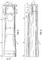
- Fig. 1 is a much enlarged, somewhat diagrammatic, transverse section of the outer member of the surgical instrument of parent application, taken across the distal aperture, with the inner member shown in dashed line, while Fig. 1a is a partial plan view of the outer member taken at the line 1a-1a of Fig. 6;
- Fig. 2 is a perspective view, partially in section, of the arthroscopic surgical instrument with a power unit and handpiece;
- Fig. 3 is an enlarged perspective of the distal portion of the outer stationary member of the instrument of Figs. 1 and 2;
- Fig. 4 is a plan view of the distal end portion of the outer stationary member of the instrument, while Fig. 5 is a side section view thereof, taken at the line 5-5 of Fig. 4, and Fig. 6 is an end view thereof, taken at the line 6-6 of Fig. 4;
- Fig. 7 is a top plan view of the inner, rotatable member of the surgical instrument of the invention, while Fig. 8 is a side view and Fig. 9 is a bottom plan view thereof;
- Fig. 10 is a somewhat diagrammatic transverse section of the surgical instrument or the invention, taken at the line 10-10 of Fig. 1;
- Fig. 11 is a somewhat diagrammatic view of the surgical instrument of the invention being employed for surgery on the meniscal cartilage of the knee;
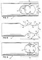
- Figs. 12 through 15 are similarly somewhat diagrammatic views, showing a sequence of tissue removal;
- Figs. 16 through 18, similarly somewhat diagrammatic, show the surgical instrument of the invention engaged for surgery upon surfaces of the joint;
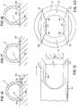
- Fig. 19 is a somewhat diagrammatic side section view of the surgical instrument of the invention engaged for cutting tissue along an edge; and
- Figs. 20 and 21 are end and plan views of the distal end of an alternate embodiment of a surgical instrument of the invention.
- Referring to Figs. 1, 2 and 3, the powered arthoscopic
surgical instrument 10 consists of an outerstationary member 12, sized for introduction into a joint of the body via a puncture opening through the flesh, and a rotatableinner member 14 coaxial with the outer member and defining adistal shearing element 16 exposed through adistal opening 18 in the side and end surfaces of the outer member. Disposed along each side edge of theaperture 18 aretable extensions 20, seen most clearly in Figs. 1 and 2, which project outwardly from the body of the outer stationary member, definingretrograde table surfaces 22 that extend beyond ablade surface 23 provided by the projection of thickness, T, of the wall of the outer member, and forming a generally concave opening into the instrument. - Referring to Fig. 2, the proximal end of
instrument 10 is received in poweredhandpiece 24, e.g., a component of the Universal Surgical System sold by Dyonics, Inc. of Andover, Massachusetts, as described by Sjostrom et al. in EP-A-189807, which is incorporated herein by reference. Thehandpiece 24 is connected proximally to a source ofsuction 26, which draws a vacuum through a conduit defined through thehandpiece 24 andinstrument 10, to aperture 18. The aperture provides communication between the interior conduit defined through the instrument and handpiece, and the environment about distal end of the instrument, the vacuum created bysuction source 26 within the conduit tending to draw uncut tissues intoaperture 18, and also evacuating, e.g., particles of tissue removed byinstrument 10, as described below. - The proximal end of rotatable
inner member 14 is associated with a reversible rotational drive motor disposed withinhandpiece 24. A controller/power source 28, connected viacable 30, powers the drive motor inhandpiece 14 at a maximum rate of up to about 1400 rpm, andfoot control 32 allows the surgeon to actuate the instrument to rotate in either direction, with his foot, leaving his hands free. - Referring to Figs. 4 and 5, the tubular, outer
stationary member 12 includes a first, generally cylindricalproximal portion 36 of substantially uniform outer diameter, D₁, e.g., 5.5 mm, or, for use in the region of the posterior horn of the meniscus, 4.0 mm. Distal ofcylindrical portion 36 lies afrustoconical portion 38 having a decreasing outer diameter in the distal direction, to diameter, D₂, of thedistal segment 40 of the instrument, which, being less than diameter, D₁, facilitates manuveuring and positioning of the distal end of the instrument within the confines of a joint. Removal of tissue from within the joint is further facilitated by a flattening of the surface of the outer member immediately proximal of theaperture 18 to form a flat, slopingsurface 42 that, in combination with the end surface opening defined by the crescent shapedistal end surface 44 defining distal end cutting edge 45 (Fig. 6), improves access of the cutting aperture of the instrument to tissue to be cut, as will be described below. - The inner surface of the
outer member 12 ataperture 18 defines a pair of axially-extending first, fixedcutting edges 46 at opposite sides of theaperture 18, adapted to coact with the cutting edges ofcutting element 16 of rotatableinner member 14, which we describe below with reference to Figs. 7-9.Table extensions 20, defining retrogradetable extension surfaces 22, project generally outwardly from the body of theouter member 12 from theblade surfaces 23 at the first, fixedcutting edges 46, as best seen in Figs. 1 and 10, by a distance, S, which is at least 20% of the thickness, T, of the sidewall of the outer member. The extension and blade surfaces at the sides of the aperture, in combination, define a substantially concave opening toaperture 18. Immediately proximal of eachtable extension 20 there is defined anotch 47 in the region of the intersection of theouter member 12 and the proximal ends of the extensions, the purpose of which will be described below. There is thus provided an outer member of construction providing maximum accessibility, in a limited space, to a tissue-shearing aperture, a particular advantage in removing relatively firm tissue at higher speeds of rotation, when the shearing behavior of the inner movable member approaches that of a smooth cylinder. - The retrograde extension surfaces defined by
table extensions 20 serve to increase the size of the tissue-receiving window offered by the instrument, as the extensions act to capture and immobilize tissue in the area of the coactingcutting edges table extension 20 extends outwardly beyond a projection, Y, of theouter surface 25 of theouter member 12, preferably by a distance, S, measured along a radius, R, about the axis of rotation, X, of the inner member, drawn through thefirst cutting edge 46. (As mentioned above, S is at least 20% of the general side wall thickness, and preferably is significantly greater than 20%, as shown, within other parameters described herein.) The angle, A, of thetable extension surface 22 to the radius, R, through thefirst cutting point 46, is greater than the angle, B, of theedge surface 23, causing the combined retrograde surface to have a component of projection, P, in the direction opposed to the direction of cutting movement, C, of theinner member 14, and providing a total immobilizing surface of area approximately double that of the edge surface alone. This retrograde relationship is further indicated by dimension, J, a projection from the radius, R₁, through point G at the intersection ofblade surface 23 andextension surface 22. The concave shape of the combinedsurfaces first cutting edge 46. Eachtable extension 20 extends outwardly to terminate in adistal surface 27 lying at or beyond a line, D, projected tangent to the path of thesecond cutting edge 66 ofinner member 14 at its midpoint, E, between thefirst cutting edges 46. - Each
table extension 20 has anouter surface 29 which is a continuation of theouter surface 25 of theouter member 12. Theouter surfaces 29 lie on, or within, parallel planes F₁, F₂, projected tangent to the opposite sides of the outer member, whereby the critical diameter, D₂, of the surgical instrument is not increased by the table extensions, and the instrument may be introduced into the narrow space between the femoral condyl and the tibial plateau, as described below with reference to Fig. 11. - The
rotatable cutter element 14 is a tube having a partially closed end, with an asymmetrical cutting arrangement defined in adistal region 16. Cuttingedges openings distal end surface 56. Each cutting edge consists of a proximal, firstcircular opening portion inner element 14, generally into its interior, and a distal second,semicircular opening portion end wall 56 of the element. The radii of the respective distal openings extend proximally to overlap the adjacent respective proximal openings, and extend distally, beyond the end surface of the cutting element. The axes (Ap, Ap', AD, AD') of the pairs of proximal and distal opening portions are longitudinally staggered from one another in order to provide a region having asymmetrical cutting action with cuttingpoints element 14 with nearly constant transverse cross sectional area along thedistal region 16 of the second cutting edges 48, 50.Element 14 is thus able to better withstand the relatively high stresses associated with the shearing of thick tissue. The longitudinally staggered cutting point arrangement also serves to minimize the risk found with other arthroscopic cutters using a rotating cutting blades having aggressive cutting tendencies, i.e., of winding tissue about the blade, dragging healthy tissue into the instrument, and provides better performance in cutting soft, slippery tissue. - The body of
cutter element 14 in the cuttingregion 16, between cutting edges, is tapered distally so that theaperture 18 remains open at nearly all rotational positions of theinner element 14 to perpetually draw target tissue toward theinstrument 10 for cutting and sculpting. Referring to Fig. 10, crescent-shapedscallops distal end surface 56 ofinner element 14, define end cutting edges adapted, in cooperation with outer member distalend cutting edge 45, to cut tissue approached from the distal end of the instrument.Scallops - Referring to Fig. 10, the rotatable
inner element 14 is disposed coaxially with and within outer stationary member 12 (the relationship is shown diagrammatically, with the end wall of the outer member removed for clarity and the inner member sectioned on a plane throughpoints inner element 14 is rotated, second cutting edges 48, 50 and cutting points 62, 64, 66 coact with the opposed first, fixedcutting edge 46 to shear tissue therebetween, while at the same time, the rotating distalend cutting edges end cutting edge 45 of the outer member to shear tissue extending into theaperture 18 from the distal end of the instrument. (As shown most clearly in Figs. 1 and 10, the instrument of the invention is constructed for tissue shearing cutting upon rotation of the inner element in either direction of rotation, as selected by the surgeon.) - Referring now to Fig. 11, the distal end of
instrument 10 is shown inserted into the joint ofknee 71 and positioned for surgical treatment, e.g., by removal of a portion of themenical cartilage 72 lying betweencondyls end 80 of the tibia 82 (shin bone). The instrument is critically sized for insertion into the tight confines of the knee joint, with the dimension, D₂, of the instrument unaffected by the table extensions, and theouter member 12 has sufficient strength to desist bending when the surgeon applies force to position the cutting end, while permitting easy passage of severed tissue-fragments through the instrument and out of the body. - Typically, during an operative procedure, the patient is given general anesthesia and appropriate punctures of the patient's flesh are made at selected points about the joint by a trocarring cannula. Fluid is introduced into one cannula at a slightly increased pressure to distend the joint, and to provide flow through the joint, through the
instrument 10. This substantial volume of flow, e.g., in excess of 100 cc per minute, is provided to ensure that all the tissue severed from the joint is drawn into the instrument and removed from the joint; it also keeps the joint fluid clear for better visual guidance of the instrument, provided via a fiber optic device inserted into the joint through another cannula. The fiber optic device introduces light to the interior of the joint from a light source and returns a visual image along a separate optical path. (The image can be directed to an eye piece for the surgeon, to recording cameras, or to a television camera which creates a display, which the surgeon watches to control his movements.) By watching the screen and manipulating the instrument, the surgeon positions the instrument for removal of tissue. - Referring now to Figs. 12 et seq., the operation of the surgical instrument of the invention for efficient removal of a variety of different tissues will now be described.
- The
extension surface 22 oftable extension 20, aboveblade surface 23 and the firstfixed cutting edge 46, has a component of projection, arrow P, opposed to the path, arrow C, of the cutting points 62, 64, 66 of the second, cuttingedges first cutting edge 46 in tissue shearing action. Referring to Fig. 12, tissue, shown representatively byrectangular shape 90, is drawn, by suction fromaperture 18 into the path of rotating cuttingelement 14. In Fig. 13, thesecond cutting edge 66 has engaged upon the surface oftissue 90 and, by rotation, exerts a drag force upon the tissue toward the shearing nip with fixededge 46, in a direction substantially normal to immobilizingsurface 22. In Fig. 14, the second cutting edge has moved toward and passed closely by the fixed cutting edge to shear afragment 92 fromtissue 90. Thefragment 92 is being drawn by suction through the instrument and ultimately out of the body. The remaining portion of thetissue 90 outside the instrument is forced against the immobilizingsurface 22 of the table extension. The tissue is thus immobilized and remains in a position (Fig. 15) which allows it to be drawn into the aperture and cut upon a subsequent pass of the cutting edges ofelement 16. Referring again to Fig. 14, feeding of the uncut tissue portion into the aperture for cutting in subsequent passes of the second cutting edges is further facilitated by the in-feed action of thecylindrical surface 94 of inner cutter element moving past thetable surface 22, creating an in-rolling nip and urging the tissue into the path of the cutting edge, and by the polished nature of thesurfaces - Powered arthroscopic surgical instruments without immobilizing table extensions typically push or bat tissue away from the instrument, e.g., due to drag and other forces applied to the tissue by the initial cutting action, and as a result produce an irregular series of cuts along the tissue surface rather than creating a smooth, continuous, sculpted surface.
Retrograde extensions 20, by immobilizing tissue, permit theinstrument 10 to be used for cutting and for tissue sculpting, and allow the surgical procedure to be performed in a markedly shorter period of time, with less trauma for the patient, and the combination of the retrograde table extension with the offset cutting points has been found to offer much improved performance in cutting tissue previously found very difficult to remove with powered instruments, e.g., plica, which is similar in nature to fibrous elastic bands. - Healthy tissue, e.g., in the joint, is typically more firm than unhealthy tissue, which tends to be soft. The
extensions 20 of the instrument of the invention are adapted to assist the surgeon to cut aggressively when removing unhealthy, degenerated tissue, and to cut less aggressively when removing healthy tissue, e.g., while sculpting or smoothing the surface of a joint. The instrument of the invention cuts tissue over a wide range of cutting speeds, e.g., from about 100 r.p.m. to 1,000 r.p.m. and above, the speed selected on the basis of tissue encountered. For example, healthy meniscal cartilage about a tear is cut at high speed; partially degenerate cartilage, which is compliant and rubbery, but still retains its form, is most effectively cut at lower speeds; and totally degenerate cartilage and synovial tissue are cut at high speeds. - Referring to Fig. 16, the
extensions 20 ofouter member 12 are arranged relative to theinner cutter member 14, (not shown), so that a line, H, between the outer tips of the extensions lies generally tangent to the path, C, of the cutting points 62, 64, 66 of the second cutting edges 48, 50 (cutting point 62, aligned axially with cuttingpoint 64, is seen in Figs. 7-9). In Fig. 16, thetable extensions 20 are engaged upon a region of generally unhealthy tissue 100, and, because of the softness of the unhealthy tissue, have sunk into the tissue to a depth, M, below thetissue surface 101. The rotating cutting element, with each rotation, penetrates into the tissue to depth, M, removing the soft, unhealthy tissue relatively aggressively. In contrast, in Fig. 17, the table extensions are engaged upon morehealthy tissue 102 and sink below thesurface 103 only to depth, N, much less than M, and cutting, shaving or scupting, proceeds much less aggressively. - In Fig. 18, the table extensions are engaged upon the
surface 104 of relativelyhard tissue 105 to provide lateral stability during removal of a nodule orridge 106 to smooth the surface. Nodules of the type shown typically consist of bone covered by soft tissue. In the past, the surgeon typically removed the soft tissue with a powered blade cutting instrument to expose the bone for removal with an abrading instrument. The exchange of instruments, necessitated by the likelihood of clogging the abrading element if it is used to remove softer tissue, is avoided with the instrument of the invention which removes the soft tissue and bone effectively and in one operation. - Referring to Fig. 19, the cutting
instrument 10 of the invention is shown in use for cuttingtissue 110 along anedge 112. The instrument is positioned in a manner to engage the edge of the tissue innotch 47 immediately proximal of thetable extension 20, and generally against the distalend cutting edge 45 of the instrument. Thenotch 47 allows the instrument to be positioned for cutting with the instrument axis closer to the edge than would be possible with instruments of other construction, thus providing for smoother and more efficient cutting and sculpting along an edge. - The instrument of the invention thus provides the physician with a single instrument that is adapted to perform debriding and sculpting of tissues within the confines of a human joint in order to reduce the trauma to the surrounding tissues inherent in removing and introducing multiple instruments during a procedure. Other embodiments are possible. For example, the position of line H relative to line C (Fig. 16) may be adjusted dependent upon the predominant nature of the procedure to be performed, e.g., H may be moved radially outwardly for smoothing osteophytes, or inwardly for more agressive cutting. The table extension may be employed with cutter instruments having inner cutter members of other configurations, e.g., auger or helical blades extending the length of the outer member or joined proximal of
aperture 18 to a shaft or inner tube. - The instrument may have a table extension along only one side of the
aperture 18. A single table extension could project outwardly to a greater degree than the table extensions of an instrument having extensions at both sides of the aperture while providing an instrument capable of passing through a cannula of the same diameter. Such an instrument would perhaps offer some advantageous features over the preferred instrument described, but at the expense of reduced versatility. - The body of the outer member may have a contour other than cylindrical, e.g., it may be more rectangular. Also, the instrument as shown in the drawing has a flat
distal surface 44, but other distal tip end shapes are contemplated, e.g., spherical, bullet-shape, or full-radius. - Referring to Figs. 20 and 21, the cutter instrument especially suited for end on cutting of, e.g.,
meniscal cartilage 107, may be provided with twoapertures 118, 118' on opposite sides of the distal end of the instrument. There may be providedtable extensions 120 at one side only of each aperture, e.g., if an auger or other inner member 114 (Fig. 21 only) capable of cutting in only one direction is provided, or with extensions at both sides of each aperture, as shown. (To provide additional strength and effective cutting, the extent of the arcs of the apertures may be reduced, placing the first cutting points 146 closer together, and thedistal end portions 113 of theouter member 112 may extend radially inwardly.
Claims (3)
- Arthroscopic surgical instrument, comprising an outer stationary member (12) sized to enter a joint through a puncture opening and having a distal aperture (18), the wall of said outer member (12) at said aperture (18) defining a first, fixed cutting edge (46),
an internal movable member (14) disposed within said outer member (12), and having at least a pair of second cutting edges (48, 50) arranged to sever tissue and adapted to be power driven for repeated, rapid movement of the second cutting edges (48, 50),
characterized by
said pair of second cutting edges being arranged to move sequentially toward and closely past said first, fixed cutting edge (46), each second cutting edge defining one or more cutting points (62, 64, 66) arranged logitudinally along said second cutting edge (48, 50), and a cutting point of one of said second cutting edges (48, 50) being offset longitudinally from a cutting point (62, 64, 66) of the next following second cutting edge (48, 50),
whereby said sequential second cutting edges (48, 50) have different cutting patterns. - Instrument of claim 1,
characterized in that
said outer member (12)
at opposite sides of said aperture (18) defines a pair of
first fixed cutting edges (46),
said internal movable member (14) being
adapted to move selectively in opposite directions and
defining
pairs of
second cutting edges (48, 50),
each said pair adapted
to coact with a respective first, fixed cutting edge (46) - Instrument of claim 1,
characterized in that
due to assymetric arrangement of said cutting points (62, 64, 66),
the body of said internal movable member (14),
in the area of said second cutting edges (48, 50),
is of substantially uniform axial section
Applications Claiming Priority (3)
| Application Number | Priority Date | Filing Date | Title |
|---|---|---|---|
| US06/948,315US4834729A (en) | 1986-12-30 | 1986-12-30 | Arthroscopic surgical instrument |
| EP87119235AEP0276478B1 (en) | 1986-12-30 | 1987-12-29 | Arthroscopic surgical instrument |
| US948315 | 1997-10-10 |
Related Parent Applications (1)
| Application Number | Title | Priority Date | Filing Date |
|---|---|---|---|
| EP87119235.7Division | 1987-12-29 |
Publications (3)
| Publication Number | Publication Date |
|---|---|
| EP0500146A2 EP0500146A2 (en) | 1992-08-26 |
| EP0500146A3 EP0500146A3 (en) | 1993-02-03 |
| EP0500146B1true EP0500146B1 (en) | 1996-02-14 |
Family
ID=25487642
Family Applications (2)
| Application Number | Title | Priority Date | Filing Date |
|---|---|---|---|
| EP87119235AExpired - LifetimeEP0276478B1 (en) | 1986-12-30 | 1987-12-29 | Arthroscopic surgical instrument |
| EP92107397AExpired - LifetimeEP0500146B1 (en) | 1986-12-30 | 1987-12-29 | Arthroscopic surgical instrument |
Family Applications Before (1)
| Application Number | Title | Priority Date | Filing Date |
|---|---|---|---|
| EP87119235AExpired - LifetimeEP0276478B1 (en) | 1986-12-30 | 1987-12-29 | Arthroscopic surgical instrument |
Country Status (5)
| Country | Link |
|---|---|
| US (1) | US4834729A (en) |
| EP (2) | EP0276478B1 (en) |
| JP (1) | JP2522508B2 (en) |
| CA (1) | CA1281964C (en) |
| DE (2) | DE3751710T2 (en) |
Families Citing this family (104)
| Publication number | Priority date | Publication date | Assignee | Title |
|---|---|---|---|---|
| US4983179A (en)* | 1986-12-30 | 1991-01-08 | Smith & Nephew Dyonics Inc. | Arthroscopic surgical instrument |
| DE3717966A1 (en)* | 1987-05-27 | 1988-12-08 | Wolf Gmbh Richard | INSTRUMENT FOR SURGICAL TREATMENT OF FABRIC PARTS |
| US4986807A (en)* | 1989-01-23 | 1991-01-22 | Interventional Technologies, Inc. | Atherectomy cutter with radially projecting blade |
| US5728129A (en)* | 1989-02-17 | 1998-03-17 | American Biomed, Inc. | Distal atherectomy catheter |
| US5087265A (en)* | 1989-02-17 | 1992-02-11 | American Biomed, Inc. | Distal atherectomy catheter |
| US4994067A (en)* | 1989-02-17 | 1991-02-19 | American Biomed, Inc. | Distal atherectomy catheter |
| US5152744A (en)* | 1990-02-07 | 1992-10-06 | Smith & Nephew Dyonics | Surgical instrument |
| US5007917A (en)* | 1990-03-08 | 1991-04-16 | Stryker Corporation | Single blade cutter for arthroscopic surgery |
| US5120318A (en)* | 1990-06-25 | 1992-06-09 | Harinathareddy Nallapareddy | Arthroscopy portal maker |
| EP0481760B1 (en)* | 1990-10-19 | 1998-05-27 | Smith & Nephew, Inc. | Surgical device |
| DE4106797C2 (en)* | 1990-11-05 | 1997-12-18 | Stefan Koscher | Surgical instrument |
| WO1992012679A1 (en)* | 1991-01-28 | 1992-08-06 | Laserscope | Process for transecting the transverse carpal ligament |
| US5425355A (en)* | 1991-01-28 | 1995-06-20 | Laserscope | Energy discharging surgical probe and surgical process having distal energy application without concomitant proximal movement |
| US5217479A (en)* | 1991-02-14 | 1993-06-08 | Linvatec Corporation | Surgical cutting instrument |
| US5352221A (en)* | 1992-11-04 | 1994-10-04 | Fumich Robert M | Guide tip apparatus for laser surgery |
| US5366465A (en)* | 1992-12-07 | 1994-11-22 | M. Ather Mirza | Endoscopic surgical procedure and instrument for implementation thereof |
| US5540706A (en)* | 1993-01-25 | 1996-07-30 | Aust; Gilbert M. | Surgical instrument |
| US5669926A (en)* | 1993-01-25 | 1997-09-23 | Aust & Taylor Medical Corporation | Surgical instrument |
| US5593416A (en)* | 1993-01-26 | 1997-01-14 | Donahue; John R. | Method of using flexible surgical instrument |
| US5282821A (en)* | 1993-01-26 | 1994-02-01 | Donahue John R | Adjustable surgical instrument |
| US5620447A (en)* | 1993-01-29 | 1997-04-15 | Smith & Nephew Dyonics Inc. | Surgical instrument |
| CA2114330A1 (en)* | 1993-01-29 | 1994-07-30 | Smith & Nephew Endoscopy, Inc. | Rotatable curved instrument |
| US5833692A (en)* | 1993-01-29 | 1998-11-10 | Smith & Nephew, Inc. | Surgical instrument |
| US5456689A (en)* | 1993-10-13 | 1995-10-10 | Arnold J. Kresch | Method and device for tissue resection |
| US5690660A (en)* | 1993-10-27 | 1997-11-25 | Stryker Corporation | Arthroscopic cutter having curved rotatable drive |
| US5437630A (en)* | 1993-10-27 | 1995-08-01 | Stryker Corporation | Arthroscopic cutter having curved rotatable drive |
| US5443474A (en)* | 1994-03-07 | 1995-08-22 | Implemed, Inc. | Meniscectomy knife |
| EP0677276B1 (en)* | 1994-04-15 | 2000-06-14 | Smith & Nephew, Inc. | Curved surgical instrument with segmented inner member |
| US5556429A (en)* | 1994-05-06 | 1996-09-17 | Advanced Bio Surfaces, Inc. | Joint resurfacing system |
| US5454827A (en)* | 1994-05-24 | 1995-10-03 | Aust; Gilbert M. | Surgical instrument |
| USRE38335E1 (en)* | 1994-05-24 | 2003-11-25 | Endius Incorporated | Surgical instrument |
| US6032673A (en)* | 1994-10-13 | 2000-03-07 | Femrx, Inc. | Methods and devices for tissue removal |
| AU701424B2 (en)* | 1994-10-24 | 1999-01-28 | Smith & Nephew, Inc. | Hollow surgical cutter with apertured flutes |
| US5665062A (en)* | 1995-01-23 | 1997-09-09 | Houser; Russell A. | Atherectomy catheter and RF cutting method |
| US5601583A (en)* | 1995-02-15 | 1997-02-11 | Smith & Nephew Endoscopy Inc. | Surgical instrument |
| US5569254A (en)* | 1995-04-12 | 1996-10-29 | Midas Rex Pneumatic Tools, Inc. | Surgical resection tool having an irrigation, lighting, suction and vision attachment |
| US5618293A (en)* | 1995-06-06 | 1997-04-08 | Smith & Nephews Dyonics, Inc. | Surgical instrument |
| US5848978A (en)* | 1995-11-14 | 1998-12-15 | Genx International, Inc. | Surgical biopsy device |
| US5676012A (en)* | 1995-12-05 | 1997-10-14 | Spectrum Manufacturing, Inc. | Process for forming endoscopic shaver blade from elongate tube |
| US5665101A (en)* | 1996-04-01 | 1997-09-09 | Linvatec Corporation | Endoscopic or open lipectomy instrument |
| US5766199A (en)* | 1996-04-10 | 1998-06-16 | Linvatec Corporation | Endoscopic shaver blade with resilient cutting edges |
| US5792167A (en)* | 1996-09-13 | 1998-08-11 | Stryker Corporation | Surgical irrigation pump and tool system |
| US6342061B1 (en) | 1996-09-13 | 2002-01-29 | Barry J. Kauker | Surgical tool with integrated channel for irrigation |
| DE69734845T2 (en)* | 1996-09-24 | 2006-09-14 | Xomed Surgical Products, Inc., North Jacksonville | Assembly of surgical blades |
| EP0873145A2 (en)* | 1996-11-15 | 1998-10-28 | Advanced Bio Surfaces, Inc. | Biomaterial system for in situ tissue repair |
| US5913867A (en)* | 1996-12-23 | 1999-06-22 | Smith & Nephew, Inc. | Surgical instrument |
| US5893862A (en)* | 1997-04-10 | 1999-04-13 | Pratt; Arthur William | Surgical apparatus |
| US5964777A (en) | 1997-12-11 | 1999-10-12 | Smith & Nephew, Inc. | Surgical cutting instrument |
| US6053923A (en)* | 1998-03-17 | 2000-04-25 | Arthrotek, Inc. | Method and apparatus for abrading tissue |
| DE29814889U1 (en)* | 1998-08-19 | 1999-12-30 | Burgard, Gunther, Dr., 66424 Homburg | Resection instrument |
| DE19945964A1 (en) | 1999-09-24 | 2001-04-05 | Biotecon Diagnostics Gmbh | Methods and nucleic acids for the detection of brewery-relevant microorganisms |
| ES2553715T3 (en)* | 2000-03-10 | 2015-12-11 | Smith & Nephew, Inc. | Apparatus for use in arthroplasty in a knee joint |
| US6419684B1 (en) | 2000-05-16 | 2002-07-16 | Linvatec Corporation | End-cutting shaver blade for axial resection |
| US6503263B2 (en)* | 2000-09-24 | 2003-01-07 | Medtronic, Inc. | Surgical micro-shaving instrument with elevator tip |
| US20030055404A1 (en)* | 2001-09-17 | 2003-03-20 | Moutafis Timothy E. | Endoscopic rotary abraders |
| US20030083681A1 (en)* | 2001-09-17 | 2003-05-01 | Moutafis Timothy E. | Surgical rotary abrader |
| US8882755B2 (en)* | 2002-03-05 | 2014-11-11 | Kimberly-Clark Inc. | Electrosurgical device for treatment of tissue |
| US8518036B2 (en) | 2002-03-05 | 2013-08-27 | Kimberly-Clark Inc. | Electrosurgical tissue treatment method |
| US6896675B2 (en) | 2002-03-05 | 2005-05-24 | Baylis Medical Company Inc. | Intradiscal lesioning device |
| US8043287B2 (en)* | 2002-03-05 | 2011-10-25 | Kimberly-Clark Inc. | Method of treating biological tissue |
| US7150747B1 (en) | 2003-01-22 | 2006-12-19 | Smith & Nephew, Inc. | Electrosurgical cutter |
| US20050065538A1 (en)* | 2003-09-22 | 2005-03-24 | Van Wyk Robert Allen | Asymmetric shaver and methods for making same |
| US8029511B2 (en)* | 2004-03-22 | 2011-10-04 | Disc Dynamics, Inc. | Multi-stage biomaterial injection system for spinal implants |
| US20060135959A1 (en)* | 2004-03-22 | 2006-06-22 | Disc Dynamics, Inc. | Nuclectomy method and apparatus |
| US7766844B2 (en) | 2004-04-21 | 2010-08-03 | Smith & Nephew, Inc. | Surgical instrument aspiration valve |
| US20060184175A1 (en)* | 2004-07-29 | 2006-08-17 | X-Sten, Inc. | Spinal ligament modification devices |
| US20090264939A9 (en)* | 2004-12-16 | 2009-10-22 | Martz Erik O | Instrument set and method for performing spinal nuclectomy |
| US20060196038A1 (en)* | 2005-03-02 | 2006-09-07 | Van Wyk Robert A | Arthroscopic shaver with two pass inner blade and method of manufacturing same |
| US20060241665A1 (en)* | 2005-04-08 | 2006-10-26 | Vance Products Incorporated, D/B/A Cook Urological Incorporated | Percutaneous and endoscopic cutters |
| US20060253198A1 (en)* | 2005-05-03 | 2006-11-09 | Disc Dynamics, Inc. | Multi-lumen mold for intervertebral prosthesis and method of using same |
| US20060253199A1 (en)* | 2005-05-03 | 2006-11-09 | Disc Dynamics, Inc. | Lordosis creating nucleus replacement method and apparatus |
| EP2335600B1 (en)* | 2005-07-29 | 2017-04-19 | Vertos Medical, Inc. | Percutaneous tissue excision devices |
| WO2007016684A2 (en)* | 2005-07-29 | 2007-02-08 | X-Sten, Corp. | Tools for percutaneous spinal ligament decompression and device for supporting same |
| US7794393B2 (en)* | 2006-04-13 | 2010-09-14 | Larsen Dane M | Resectoscopic device and method |
| US7942830B2 (en) | 2006-05-09 | 2011-05-17 | Vertos Medical, Inc. | Ipsilateral approach to minimally invasive ligament decompression procedure |
| DE102006034756A1 (en)* | 2006-07-24 | 2008-01-31 | Karl Storz Gmbh & Co. Kg | Medical instrument for cutting tissue |
| US7456107B2 (en)* | 2006-11-09 | 2008-11-25 | Cabot Microelectronics Corporation | Compositions and methods for CMP of low-k-dielectric materials |
| CN100457054C (en)* | 2007-03-19 | 2009-02-04 | 孙茂莲 | Forceps for removing submucous myoma of uterus |
| US20090118709A1 (en)* | 2007-11-06 | 2009-05-07 | Vertos Medical, Inc. A Delaware Corporation | Tissue Excision Tool, Kits and Methods of Using the Same |
| EP2285312A4 (en) | 2008-05-01 | 2014-03-12 | Columna Pty Ltd | Systems methods and apparatuses for formation and insertion of tissue prostheses |
| USD619252S1 (en) | 2008-10-23 | 2010-07-06 | Vertos Medical, Inc. | Tissue modification device |
| USD621939S1 (en) | 2008-10-23 | 2010-08-17 | Vertos Medical, Inc. | Tissue modification device |
| USD611146S1 (en) | 2008-10-23 | 2010-03-02 | Vertos Medical, Inc. | Tissue modification device |
| USD635671S1 (en) | 2008-10-23 | 2011-04-05 | Vertos Medical, Inc. | Tissue modification device |
| USD619253S1 (en) | 2008-10-23 | 2010-07-06 | Vertos Medical, Inc. | Tissue modification device |
| USD610259S1 (en) | 2008-10-23 | 2010-02-16 | Vertos Medical, Inc. | Tissue modification device |
| US8523891B2 (en)* | 2009-02-23 | 2013-09-03 | Microaire Surgical Instruments, Llc | Probe for carpal tunnel release tool or tissue dissection |
| US8574254B2 (en) | 2011-01-25 | 2013-11-05 | Smith & Nephew, Inc. | Arthroscopic cutting blade |
| US11076840B2 (en) | 2011-12-02 | 2021-08-03 | Interscope, Inc. | Surgical console, specimen receiver, and insertable endoscopic instrument for tissue removal |
| US8882680B2 (en) | 2011-12-02 | 2014-11-11 | Interscope, Inc. | Insertable endoscopic instrument for tissue removal |
| US9808146B2 (en)* | 2011-12-02 | 2017-11-07 | Interscope, Inc. | Endoscopic tool for debriding and removing polyps |
| US9204868B2 (en) | 2011-12-02 | 2015-12-08 | Interscope, Inc. | Methods and apparatus for removing material from within a mammalian cavity using an insertable endoscopic instrument |
| USD855802S1 (en) | 2011-12-23 | 2019-08-06 | Interscope, Inc. | Disposable tool |
| US20160030014A1 (en)* | 2014-07-30 | 2016-02-04 | Covidien Lp | Exchangeable core biopsy needle |
| US9737322B2 (en)* | 2014-09-08 | 2017-08-22 | Medtronic Xomed, Inc. | Method for resection of tumors and tissues |
| US9636132B2 (en) | 2014-09-08 | 2017-05-02 | Medtronic Xomed, Inc. | Tumor debulker |
| DE102014219616A1 (en)* | 2014-09-26 | 2016-03-31 | Geuder Ag | Device for cutting tissue |
| ITUA20162135A1 (en) | 2016-03-31 | 2017-10-01 | Medacta Int Sa | GUIDE AND PROTECTION ELEMENT FOR BONE REMOVAL INSTRUMENTS AND BONE REMOVAL INSTRUMENT INCLUDING THIS ELEMENT |
| EP4368128A3 (en) | 2016-09-07 | 2024-07-17 | Vertos Medical, Inc. | Percutaneous lateral recess resection methods and instruments |
| WO2019028221A1 (en) | 2017-08-02 | 2019-02-07 | Stryker Corporation | Surgical tool systems, and methods of use thereof |
| US11376022B2 (en) | 2019-07-18 | 2022-07-05 | Quadvantage Technology, Inc. | Patella cutting guide |
| DE102020122718A1 (en)* | 2020-08-31 | 2022-03-03 | Sven Behrendt | surgical shaver |
| US20220370091A1 (en)* | 2021-05-18 | 2022-11-24 | Quadvantage Technology, Inc. | Surgical cutting blade using composite materials |
| US20230404561A1 (en) | 2022-06-16 | 2023-12-21 | Vertos Medical, Inc. | Integrated instrument assembly |
Family Cites Families (23)
| Publication number | Priority date | Publication date | Assignee | Title |
|---|---|---|---|---|
| US1867624A (en)* | 1930-04-01 | 1932-07-19 | Memorial Hospital For The Trea | Device for obtaining biopsy specimens |
| US2070281A (en)* | 1935-07-12 | 1937-02-09 | Leggiadro Vincent | Surgical knife |
| US3618611A (en)* | 1969-03-05 | 1971-11-09 | Julius C Urban | Vacuum rotary dissector |
| US3990453A (en)* | 1973-04-25 | 1976-11-09 | Douvas Nicholas G | Apparatus for cataract surgery |
| US4018228A (en)* | 1975-02-24 | 1977-04-19 | Goosen Carl C | Surgical punch apparatus |
| US3995619A (en)* | 1975-10-14 | 1976-12-07 | Glatzer Stephen G | Combination subcutaneous suture remover, biopsy sampler and syringe |
| US4111207A (en)* | 1976-10-28 | 1978-09-05 | David Kopf Instruments | Notched tubular cutting instrument |
| US4203444A (en)* | 1977-11-07 | 1980-05-20 | Dyonics, Inc. | Surgical instrument suitable for closed surgery such as of the knee |
| US4258716A (en)* | 1978-02-06 | 1981-03-31 | The University Of Melbourne | Microsurgical instruments |
| US4513745A (en)* | 1978-06-21 | 1985-04-30 | Amoils Selig P | Surgical instruments and methods particularly adapted for intra-ocular cutting and the like |
| US4274414A (en)* | 1979-02-21 | 1981-06-23 | Dyonics, Inc. | Surgical instrument |
| US4239045A (en)* | 1979-04-04 | 1980-12-16 | Schlein Allen P | Surgical knife |
| US4461305A (en)* | 1981-09-04 | 1984-07-24 | Cibley Leonard J | Automated biopsy device |
| JPS59200644A (en)* | 1983-04-27 | 1984-11-14 | オリンパス光学工業株式会社 | Surgical incision instrument |
| US4579118A (en)* | 1983-06-01 | 1986-04-01 | Ethicon, Inc. | Hemostatic clip with penetration means |
| US4586497A (en)* | 1983-10-31 | 1986-05-06 | David J. Dapra | Drill fixation device and method for vertebra cutting |
| US4543857A (en)* | 1983-12-09 | 1985-10-01 | Urban Engineering Co., Inc. | Surgical instrument and method of making same |
| JPS60142842A (en)* | 1983-12-28 | 1985-07-29 | オリンパス光学工業株式会社 | Surgical incision instrument |
| US4598710A (en)* | 1984-01-20 | 1986-07-08 | Urban Engineering Company, Inc. | Surgical instrument and method of making same |
| US4572181A (en)* | 1984-03-15 | 1986-02-25 | Martin Mattler | Clamping/cutting apparatus |
| US4672965A (en)* | 1984-08-16 | 1987-06-16 | Gilbert Baum | Surgical apparatus |
| US4649919A (en)* | 1985-01-23 | 1987-03-17 | Precision Surgical Instruments, Inc. | Surgical instrument |
| JPS61199851A (en)* | 1985-02-28 | 1986-09-04 | オリンパス光学工業株式会社 | Surgical incision instrument |
- 1986
- 1986-12-30USUS06/948,315patent/US4834729A/ennot_activeExpired - Lifetime
- 1987
- 1987-12-29DEDE3751710Tpatent/DE3751710T2/ennot_activeExpired - Fee Related
- 1987-12-29CACA000555457Apatent/CA1281964C/ennot_activeExpired - Lifetime
- 1987-12-29EPEP87119235Apatent/EP0276478B1/ennot_activeExpired - Lifetime
- 1987-12-29EPEP92107397Apatent/EP0500146B1/ennot_activeExpired - Lifetime
- 1987-12-29DEDE3751318Tpatent/DE3751318T2/ennot_activeExpired - Fee Related
- 1988
- 1988-01-04JPJP63000249Apatent/JP2522508B2/ennot_activeExpired - Fee Related
Also Published As
| Publication number | Publication date |
|---|---|
| EP0276478B1 (en) | 1995-05-24 |
| JP2522508B2 (en) | 1996-08-07 |
| JPS63197445A (en) | 1988-08-16 |
| US4834729A (en) | 1989-05-30 |
| EP0500146A3 (en) | 1993-02-03 |
| EP0500146A2 (en) | 1992-08-26 |
| DE3751710T2 (en) | 1996-09-12 |
| DE3751318T2 (en) | 1995-11-02 |
| EP0276478A1 (en) | 1988-08-03 |
| CA1281964C (en) | 1991-03-26 |
| DE3751318D1 (en) | 1995-06-29 |
| DE3751710D1 (en) | 1996-03-28 |
Similar Documents
| Publication | Publication Date | Title |
|---|---|---|
| EP0500146B1 (en) | Arthroscopic surgical instrument | |
| US4983179A (en) | Arthroscopic surgical instrument | |
| US4203444A (en) | Surgical instrument suitable for closed surgery such as of the knee | |
| US6610066B2 (en) | Suction rasp and handpiece adapter assembly and powered surgical handpiece assembly including a suction rasp | |
| EP0800794B1 (en) | Endoscopic shaver blade with resilient cutting edges | |
| CA2251658C (en) | Surgical cutting device removably connected to a rotary drive element | |
| US4842578A (en) | Surgical abrading instrument | |
| US6419684B1 (en) | End-cutting shaver blade for axial resection | |
| EP0807413B1 (en) | Endoscopic or open lipectomy instrument | |
| EP0552980B1 (en) | Apparatus for performing endoscopic surgery | |
| US5327896A (en) | Suction downbiter | |
| WO1993015665A1 (en) | Surgical instrument for cutting hard tissue and method of use | |
| JP2001507590A (en) | Surgical instruments | |
| EP0669105A2 (en) | Endoscopic resection instrument | |
| KR102720891B1 (en) | Endoscopic resection cap with built-in vibratory dissector | |
| RU2176903C2 (en) | Bone mill and method for using it | |
| CA1145636A (en) | Surgical instrument suitable for closed surgery such as of the knee | |
| JPH0622332Y2 (en) | Surgical cutting instrument | |
| JPH0557862B2 (en) | ||
| JPH03143437A (en) | Surgical ablation tool | |
| JPH0481459B2 (en) |
Legal Events
| Date | Code | Title | Description |
|---|---|---|---|
| PUAI | Public reference made under article 153(3) epc to a published international application that has entered the european phase | Free format text:ORIGINAL CODE: 0009012 | |
| AC | Divisional application: reference to earlier application | Ref document number:276478 Country of ref document:EP | |
| AK | Designated contracting states | Kind code of ref document:A2 Designated state(s):DE FR GB | |
| PUAL | Search report despatched | Free format text:ORIGINAL CODE: 0009013 | |
| AK | Designated contracting states | Kind code of ref document:A3 Designated state(s):DE FR GB | |
| RAP1 | Party data changed (applicant data changed or rights of an application transferred) | Owner name:SMITH & NEPHEW DYONICS, INC. | |
| 17P | Request for examination filed | Effective date:19930928 | |
| 17Q | First examination report despatched | Effective date:19941124 | |
| GRAA | (expected) grant | Free format text:ORIGINAL CODE: 0009210 | |
| AC | Divisional application: reference to earlier application | Ref document number:276478 Country of ref document:EP | |
| AK | Designated contracting states | Kind code of ref document:B1 Designated state(s):DE FR GB | |
| REF | Corresponds to: | Ref document number:3751710 Country of ref document:DE Date of ref document:19960328 | |
| ET | Fr: translation filed | ||
| PLBE | No opposition filed within time limit | Free format text:ORIGINAL CODE: 0009261 | |
| STAA | Information on the status of an ep patent application or granted ep patent | Free format text:STATUS: NO OPPOSITION FILED WITHIN TIME LIMIT | |
| 26N | No opposition filed | ||
| REG | Reference to a national code | Ref country code:FR Ref legal event code:TP | |
| REG | Reference to a national code | Ref country code:GB Ref legal event code:IF02 | |
| PGFP | Annual fee paid to national office [announced via postgrant information from national office to epo] | Ref country code:FR Payment date:20041208 Year of fee payment:18 | |
| PGFP | Annual fee paid to national office [announced via postgrant information from national office to epo] | Ref country code:DE Payment date:20041223 Year of fee payment:18 | |
| PGFP | Annual fee paid to national office [announced via postgrant information from national office to epo] | Ref country code:GB Payment date:20041229 Year of fee payment:18 | |
| PG25 | Lapsed in a contracting state [announced via postgrant information from national office to epo] | Ref country code:GB Free format text:LAPSE BECAUSE OF NON-PAYMENT OF DUE FEES Effective date:20051229 | |
| PG25 | Lapsed in a contracting state [announced via postgrant information from national office to epo] | Ref country code:DE Free format text:LAPSE BECAUSE OF NON-PAYMENT OF DUE FEES Effective date:20060701 | |
| GBPC | Gb: european patent ceased through non-payment of renewal fee | Effective date:20051229 | |
| PG25 | Lapsed in a contracting state [announced via postgrant information from national office to epo] | Ref country code:FR Free format text:LAPSE BECAUSE OF NON-PAYMENT OF DUE FEES Effective date:20060831 | |
| REG | Reference to a national code | Ref country code:FR Ref legal event code:ST Effective date:20060831 |