EP0498739B1 - Interrupter and change-over switch for high tension arrangement - Google Patents
Interrupter and change-over switch for high tension arrangementDownload PDFInfo
- Publication number
- EP0498739B1 EP0498739B1EP92400332AEP92400332AEP0498739B1EP 0498739 B1EP0498739 B1EP 0498739B1EP 92400332 AEP92400332 AEP 92400332AEP 92400332 AEP92400332 AEP 92400332AEP 0498739 B1EP0498739 B1EP 0498739B1
- Authority
- EP
- European Patent Office
- Prior art keywords
- contact
- contacts
- high voltage
- mobile
- sleeve
- Prior art date
- Legal status (The legal status is an assumption and is not a legal conclusion. Google has not performed a legal analysis and makes no representation as to the accuracy of the status listed.)
- Expired - Lifetime
Links
- 239000011810insulating materialSubstances0.000claimsdescription17
- 238000006073displacement reactionMethods0.000claimsdescription10
- -1polyethylenePolymers0.000claimsdescription4
- 229920000642polymerPolymers0.000claimsdescription3
- 239000004698PolyethyleneSubstances0.000claimsdescription2
- 239000004743PolypropyleneSubstances0.000claimsdescription2
- 229920000573polyethylenePolymers0.000claimsdescription2
- 229920001155polypropylenePolymers0.000claimsdescription2
- 230000005611electricityEffects0.000claims1
- 238000010586diagramMethods0.000description3
- 238000010894electron beam technologyMethods0.000description3
- 238000002955isolationMethods0.000description3
- 230000015556catabolic processEffects0.000description2
- 238000009413insulationMethods0.000description2
- 239000002184metalSubstances0.000description2
- 125000006850spacer groupChemical group0.000description2
- 229920000297RayonPolymers0.000description1
- 238000013459approachMethods0.000description1
- 239000004020conductorSubstances0.000description1
- 230000001627detrimental effectEffects0.000description1
- 238000003745diagnosisMethods0.000description1
- 238000010891electric arcMethods0.000description1
- 230000004907fluxEffects0.000description1
- 238000003780insertionMethods0.000description1
- 230000037431insertionEffects0.000description1
- 238000009434installationMethods0.000description1
- 239000008188pelletSubstances0.000description1
- 239000002964rayonSubstances0.000description1
- 230000001360synchronised effectEffects0.000description1
Images


Classifications
- H—ELECTRICITY
- H05—ELECTRIC TECHNIQUES NOT OTHERWISE PROVIDED FOR
- H05G—X-RAY TECHNIQUE
- H05G1/00—X-ray apparatus involving X-ray tubes; Circuits therefor
- H05G1/08—Electrical details
- H—ELECTRICITY
- H01—ELECTRIC ELEMENTS
- H01H—ELECTRIC SWITCHES; RELAYS; SELECTORS; EMERGENCY PROTECTIVE DEVICES
- H01H33/00—High-tension or heavy-current switches with arc-extinguishing or arc-preventing means
- H01H33/02—Details
- H01H33/04—Means for extinguishing or preventing arc between current-carrying parts
- H01H33/06—Insulating body insertable between contacts
- H—ELECTRICITY
- H05—ELECTRIC TECHNIQUES NOT OTHERWISE PROVIDED FOR
- H05G—X-RAY TECHNIQUE
- H05G1/00—X-ray apparatus involving X-ray tubes; Circuits therefor
- H05G1/08—Electrical details
- H05G1/56—Switching-on; Switching-off
- Y—GENERAL TAGGING OF NEW TECHNOLOGICAL DEVELOPMENTS; GENERAL TAGGING OF CROSS-SECTIONAL TECHNOLOGIES SPANNING OVER SEVERAL SECTIONS OF THE IPC; TECHNICAL SUBJECTS COVERED BY FORMER USPC CROSS-REFERENCE ART COLLECTIONS [XRACs] AND DIGESTS
- Y10—TECHNICAL SUBJECTS COVERED BY FORMER USPC
- Y10T—TECHNICAL SUBJECTS COVERED BY FORMER US CLASSIFICATION
- Y10T74/00—Machine element or mechanism
- Y10T74/18—Mechanical movements
- Y10T74/18992—Reciprocating to reciprocating
- Y—GENERAL TAGGING OF NEW TECHNOLOGICAL DEVELOPMENTS; GENERAL TAGGING OF CROSS-SECTIONAL TECHNOLOGIES SPANNING OVER SEVERAL SECTIONS OF THE IPC; TECHNICAL SUBJECTS COVERED BY FORMER USPC CROSS-REFERENCE ART COLLECTIONS [XRACs] AND DIGESTS
- Y10—TECHNICAL SUBJECTS COVERED BY FORMER USPC
- Y10T—TECHNICAL SUBJECTS COVERED BY FORMER US CLASSIFICATION
- Y10T74/00—Machine element or mechanism
- Y10T74/20—Control lever and linkage systems
- Y10T74/20012—Multiple controlled elements
Definitions
- the inventionrelates to high voltage switches and, more particularly, those which are used to alternately supply at least two x-ray tubes from a single high voltage generator.
- X-ray tubesfor medical diagnosis for example, are generally constituted (FIG. 1) like a diode, that is to say with a cathode 11 and an anode 12 or anti-cathode, these two electrodes being enclosed in a envelope 14 vacuum tight and which allows for electrical isolation between these two electrodes.
- the cathode 11produces an electron beam 13 and the anode receives these electrons over a small surface which constitutes a focal point from which the X-rays are emitted.
- the rotary anode of the conventional typehas the general shape of a disc having an axis of symmetry 16 around which it is rotated by means of an electric motor 17; the electric motor has a stator 18 located outside the envelope 14 and a rotor 19 mounted in the envelope 14 of the X-ray tube and arranged along the axis of symmetry 16, the rotor being mechanically secured to the anode via a support shaft 20.
- the high voltage generator 15which supplies between the terminals -HT and + HT a voltage of between 50 and 160 kilovolts, is an important, bulky and expensive element of an X-ray device. Also, in radiology installations comprising several X-ray tubes, provision is made to use only one high voltage generator which is connected to the various X-ray tubes by means of a high voltage switch, the basic diagram is given by FIG. 2 in the case of a switch 21 for supplying two tubes A and B. It comprises two input terminals 22 and 23 connected respectively to the terminals + HT and -HT of the high generator voltage and two pairs of output terminals 24, 25 and 26, 27 respectively connected to tubes A and B.
- the switchingis carried out by two rotary arms 28 and 29 connected on one side (pads 22 ′ and 23 ′) respectively input terminals 22 and 23 and the other is at output terminals 24 and 25 (pads 24 ′ and 25 ′) for a first position of the arms (supply of tube A), or at the output terminals 26 and 27 (pads 26 ′ and 27 ′) for a second position of the arms (supply of tube B).
- the distances separating the different padsare large enough to avoid conduction by electric arc.
- the distancesshould be of the order of several centimeters, for example 15 centimeters for 150 kilovolts, which leads to switches of large dimensions and therefore very bulky.
- US-A-2,714,144describes a switch device according to the preamble of claim 1 in which a movable contact, mounted on an elastic arm is separated from a fixed contact by the rotation of an insulating element which slides against the face of the movable contact so as to move the latter and to be inserted between the two contacts.
- Such a switch device of the prior arthas the major drawback that the spacing and bringing together of the contacts is obtained by contact and friction of the insulating element against the movable contact, which causes rapid wear of this movable contact and of the insulating element.
- the object of the present inventionis therefore to produce a high voltage switch device in which the spacing and the approximation of the movable contact relative to the fixed contact is effected without friction on the movable or fixed contact.
- the inventiontherefore relates to a high-voltage switch device comprising a fixed stud and a movable stud which are arranged opposite one another, the movable stud being mounted at one end of an elastic curved blade which is mobile in the direction of the fixed stud while the other end is fixed, and means for isolating and moving the mobile end of the blade so that, in a first position, the movable stud comes into contact with the fixed stud while in a second position, the movable stud is distant from the fixed stud and is separated from the latter by an element of insulating material, characterized in that the means of insulation and displacement comprise means for displacing in a coordinated manner, on the one hand, the movable end of the curved blade in a longitudinal direction relative to the blade and, on the other hand, the element of insulating material between the fixed pad and the movable pad, without contact with said pads.
- the element of insulating materialcomprises a sleeve of insulating material, the wall of which has an orifice, for the passage of the movable stud, said sleeve being mounted to rotate around a fixed circular element.
- the sleeveis connected to the conductive and elastic blade by an articulated arm, the end of which is guided by a slot in said circular element which is arranged parallel to the conductive and elastic blade, so that the rotation of the sleeve in one direction moves the longitudinal movable stud to come into contact with the fixed stud crossing the wall of the sleeve through the orifice of the wall while the rotation in the opposite direction moves the mobile contact away from the fixed contact and interposes the wall of the sleeve between the two studs.
- a high voltage switch for applying or not applying a high voltage (+ HT, -HT) to a device for use such as an X-ray tubeis characterized in that it comprises two switch devices described above, the pads of which of the same type are connected one to high voltage + HT and the other to high voltage -HT while the pads of the other type are connected to the device of use and a device for controlling the synchronous rotation of the isolation and displacement means.
- a high voltage switchfor applying a high voltage (+ HT, -HT) either to a first use device such as a first X-ray tube, or to a second use device such as a second tube high voltage -HT and whose movable pads are connected in pairs to the first and second use devices and a device for controlling the rotation in synchronism of the isolation and displacement means for, in a first position, establishing the contact between the pads of the switch devices associated with the first use device while the pads of the switch devices associated with the second use device are open and, in a second position, establish contact between the pads of the switch devices associated with the second device of use while the pads of the switch devices associated with the first use device are open.
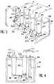
- a switch according to the inventioncomprises (FIG. 3) a housing 31 which serves as a support for the various switching elements proper and for the various electrical connectors for input and output of the high voltage.
- the electrical connectors 32 to 37comprise two input connectors 32 and 33 which are respectively connected to the two poles + HT and -HT of the high voltage generator 15 (FIG. 1) and four output connectors 34 to 37 which are connected to the terminals d 'high voltage input of tubes A and B X-ray.
- each connectoris constituted by a female part, shown in Figures 3 and 4, in which fits a male part, not shown, which is connected by a cable either to the high-voltage generator or to the x-ray tubes.
- Each female part 32 ′ to 37 ′has the shape of a circular section sleeve, made of insulating material, comprising an open end for the interlocking of the male part and a closed end which carries electrical studs 39.
- each sleevehas an external flange, referenced 33c and 37c for the connectors 33 and 37, which rests on the edge of a circular orifice drilled in the cover 38 of the housing 31 so that the electrical studs are located inside the housing.
- An electrical pad 39 of the input connector 32is connected, for example, to two fixed contacts 34f and 35f ( Figure 7) associated respectively with the output connectors 34 and 35 while an electrical pad 39 of the input connector 33 is connected to the two other fixed contacts 36f and 37f ( Figure 7) associated respectively with the output connectors 36 and 37.
- the fixed contacts 34f, 35f, 36f and 37fare carried by a rigid strip 40 secured to one of the walls of the housing 31.
- Each fixed contact 34f to 37fis disposed respectively opposite a movable contact 34m to 37m carried by a contact device 34d to 37d which is mounted on the electrical pads 39 of each female part 34 ′ to 37′ of a connector of exit 34 to 37.
- each movable contact device 34d to 37dcomprises a sleeve 41, made of insulating material, of circular cross section whose inner wall has two shoulders 50 and 51 separated by a distance b against which s 'support two circular pads of insulating material 42 and 43.
- the pad 42is fixed to the female part by nuts 44 and 45 screwed onto the threaded ends of the electrical pads 46 and 47, respectively.
- the pad 43is fixed to the pad 42 by means of spacers and screws such as those referenced 48 and 49 in the figure 5-a. The length of the spacers is equal to the distance b between the shoulders 50 and 51, which allows the sleeve 41 to rotate around the pellets 42 and 43.
- the movable contact mis disposed between the two pads 42 and 43 and is carried by a blade 52 at one end, the other end of said blade being fixed to the electrical pad 47 which must apply the high voltage to the tube.
- This blade 52made of conductive metal, has a straight portion 53 which runs along the pad 43 and a curved portion 54, near the pad 47, which is flexible in the direction of the movable contact m and vice versa.
- the displacement of the movable contact mis obtained by an arm 55, one end of which is fixed to the blade 52 and the other end of which is fixed to the sleeve 41.
- the fixing to the blade 52is carried out by means of a notch 56 which is parallel to the blade so as to serve as a guide and the attachment to the sleeve 41 is carried out by a screw 57 passing through a notch formed in the wall of the sleeve.
- the wall of the sleeve 41has a notch 58 at the level of the space separating the two pads 42 and 43.
- the position of this notch 58 on the periphery of the sleeve and its lengthare such that they allow the blade 52 to pass so that the contact m comes to abut on the fixed contact f for the position of the sleeve and of the arm 55 shown in FIGS. 5-b and 6-b; in this position, the end of the blade 52, on the movable contact side m, abuts on the edge of the notch, which stops the rotation of the sleeve 41 and, consequently, the movement of the movable contact towards the fixed contact.
- the position of the other edge of the notchis determined by the length of the movement made by the contact movable in its withdrawal movement with respect to the length of the distance which diametrically separates the fixed contact from the inside of the wall of the sleeve: when these two lengths are equal, the wall of the sleeve can be interposed between the movable contact and fixed contact and constitutes a very effective insulation.
- the wall of the sleeveIn the position of the movable contact furthest from the fixed contact (figures 5-a and 6-a), the wall of the sleeve must separate the two contacts; if the rotational movement of the sleeve is continued beyond, the movable contact approaches the fixed contact and abuts against the internal wall of the sleeve, which stops its movement.
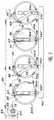
- FIG. 7shows the respective positions of the sleeves and of the contacts of the switch according to the invention in the case of the alternating supply of two X-ray tubes A and B as well as the position of the device for controlling the rotation of the sleeves.
- the contact devices 35d and 37dare shown in the closed position while the contact devices 34d and 36d are shown in the open position such that the wall of the sleeve 41 is interposed between the two contacts.
- the device for controlling the rotation of the four sleevesis constituted by a rigid bar 60 in insulating material which is intended to move longitudinally from left to right (arrow 61) and from right to left under the action of a rod 62 of insulating material with rotary movement which carries a lug 64 cooperating with a groove 63 of the bar 60.
- the bar 60has grooves or notches 65 to 68 in a direction parallel to the flexible blades 52 which cooperate respectively with lugs 69 to 71 carried respectively by the periphery of the sleeves 34d to 37d.
- the high voltage switchshows that it consists of four high voltage switch devices which each independently carry out the closing or opening of the facing contacts, the space separating the contacts in position d opening being occupied by the insulating wall of the sleeve.
- a bipolar switchcan then be produced using two switch devices, one switch device per pole.
- insulating materialwith high electrical rigidity, rigidity which corresponds to a breakdown voltage of several tens of kilovolts per millimeter.
- This insulating materialis preferably a polymer such as polyethylene or polypropylene.
- the elements referenced 80 and 81are electrical conductors which are used for the electrical supply of the filament of the cathode of the tube with X-ray tube.
Landscapes
- X-Ray Techniques (AREA)
Description
Translated fromFrenchL'invention concerne les commutateurs haute tension et, plus particulièrement, ceux qui sont utilisés pour alimenter alternativement au moins deux tubes à rayons X à partir d'un générateur haute tension unique.The invention relates to high voltage switches and, more particularly, those which are used to alternately supply at least two x-ray tubes from a single high voltage generator.
Les tubes à rayons X, pour diagnostic médical par exemple, sont généralement constitués (figure 1) comme une diode, c'est-à-dire avec une cathode 11 et une anode 12 ou anti-cathode, ces deux électrodes étant enfermées dans une enveloppe 14 étanche au vide et qui permet de réaliser l'isolement électrique entre ces deux électrodes. La cathode 11 produit un faisceau d'électrons 13 et l'anode reçoit ces électrons sur une petite surface qui constitue un foyer d'où sont émis les rayons X.X-ray tubes, for medical diagnosis for example, are generally constituted (FIG. 1) like a diode, that is to say with a
Quand la haute tension d'alimentation est appliquée par un générateur 15 aux bornes de la cathode 11 et de l'anode 12 de façon que la cathode soit au potentiel négatif -HT et l'anode au potentiel +HT, un courant dit courant anodique s'établit dans le circuit au travers du générateur 15 produisant la haute tension; le courant anodique traverse l'espace entre le cathode et l'anode sous la forme du faisceau d'électrons 13 qui bombardent le foyer.When the high supply voltage is applied by a
Une faible proportion de l'énergie dépensée à produire le faisceau d'électrons 13 est transformée en rayons X, le reste de cette énergie étant transformé en chaleur.A small proportion of the energy expended in producing the
Aussi, compte tenu également des puissances instantanées importantes mises en jeu (de l'ordre de 100 KW) et des petites dimensions du foyer (de l'ordre du millimètre), les constructeurs ont depuis longtemps réalisé des tubes à rayons X à anode tournante où l'anode est mise en rotation pour répartir le flux thermique sur une couronne appelée couronne focale, d'aire beaucoup plus grande que le foyer, l'intérêt étant d'autant plus grand que la vitesse de rotation est élevée (en général entre 3.000 et 12.000 tours par minute).Also, given also the large instantaneous powers involved (of the order of 100 KW) and the small dimensions of the hearth (of the order of a millimeter), manufacturers have long produced tubes X-ray rotary anode where the anode is rotated to distribute the heat flux over a ring called focal ring, with a much larger area than the focus, the advantage being all the greater as the speed of rotation is high (generally between 3,000 and 12,000 revolutions per minute).
L'anode tournante de type classique a la forme générale d'un disque ayant un axe de symétrie 16 autour duquel elle est mise en rotation à l'aide d'un moteur électrique 17; le moteur électrique a un stator 18 situé à l'extérieur de l'enveloppe 14 et un rotor 19 monté dans l'enveloppe 14 du tube à rayons X et disposé selon l'axe de symétrie 16, le rotor étant mécaniquement solidarisé à l'anode par l'intermédiaire d'un arbre support 20.The rotary anode of the conventional type has the general shape of a disc having an axis of
Le générateur haute tension 15, qui fournit entre les bornes -HT et +HT une tension comprise entre 50 et 160 kilovolts, est un élément important, volumineux et coûteux d'un appareil radiologique. Aussi, dans les installations de radiologie comportant plusieurs tubes à rayons X, il est prévu de n'utiliser qu'un seul générateur haute tension que l'on connecte aux différents tubes à rayons X par l'intermédiaire d'un commutateur haute tension dont le schéma de principe est donné par la figure 2 dans le cas d'un commutateur 21 d'alimentation de deux tubes A et B. Il comprend deux bornes d'entrée 22 et 23 connectées respectivement aux bornes +HT et -HT du générateur haute tension et deux paires de bornes de sortie 24, 25 et 26, 27 connectées respectivement aux tubes A et B. La commutation est réalisée grâce à deux bras rotatifs 28 et 29 connectés d'un côté (plots 22′ et 23′) respectivement aux bornes d'entrée 22 et 23 et de l'autre soit aux bornes de sortie 24 et 25 (plots 24′ et 25′) pour une première position des bras (alimentation du tube A), soit aux bornes de sortie 26 et 27 (plots 26′ et 27′) pour une deuxième position des bras (alimentation du tube B). Avec un tel mécanisme, il est nécessaire que les distances séparant les différents plots soient suffisamment grandes pour éviter une conduction par arc électrique. Ainsi, dans l'air sec, les distances devront être de l'ordre de plusieurs centimètres, par exemple 15 centimètres pour 150 kilovolts, ce qui conduit à des commutateurs de grandes dimensions et donc très encombrants. Aussi, pour réduire cet encombrement, il est habituel de disposer le ou les commutateurs dans une enceinte remplie d'huile isolante dont la tension de claquage est égale ou supérieure à 10 kilovolts par millimètre au lieu d'un kilovolt par millimètre dans l'air sec. Ceci conduit, bien entendu, à un encombrement réduit mais avec la sujétion de l'utilisation d'une enceinte remplie d'huile.The
Le brevet US-A-2 714 144 décrit un dispositif interrupteur conforme au préambule de la revendication 1 dans lequel un contact mobile, monté sur un bras élastique est écarté d'un contact fixe par la rotation d'un élément isolant qui vient glisser contre la face du contact mobile de manière à déplacer ce dernier et à s'intercaler entre les deux contacts.US-A-2,714,144 describes a switch device according to the preamble of claim 1 in which a movable contact, mounted on an elastic arm is separated from a fixed contact by the rotation of an insulating element which slides against the face of the movable contact so as to move the latter and to be inserted between the two contacts.
Un tel dispositif interrupteur de l'art antérieur présente l'inconvénient majeur que l'écartement et le rapprochement des contacts est obtenu par contact et frottement de l'élément isolant contre le contact mobile, ce qui provoque une usure rapide de ce contact mobile et de l'élément isolant.Such a switch device of the prior art has the major drawback that the spacing and bringing together of the contacts is obtained by contact and friction of the insulating element against the movable contact, which causes rapid wear of this movable contact and of the insulating element.
Le but de la présente invention est donc de réaliser un dispositif interrupteur haute tension dans lequel l'écartement et le rapprochement du contact mobile par rapport au contact fixe s'effectue sans frottement sur le contact mobile ou fixe.The object of the present invention is therefore to produce a high voltage switch device in which the spacing and the approximation of the movable contact relative to the fixed contact is effected without friction on the movable or fixed contact.
L'invention concerne donc un dispositif interrupteur haute tension comprenant un plot fixe et un plot mobile qui sont disposés en regard l'un de l'autre, le plot mobile étant monté à une extrémité d'une lame courbe élastique qui est mobile en direction du plot fixe tandis que l'autre extrémité est fixe, et des moyens d'isolation et de déplacement de l'extrémité mobile de la lame de manière que, dans une première position, le plot mobile vienne en contact avec le plot fixe tandis que, dans une deuxième position, le plot mobile soit éloigné du plot fixe et soit séparé de ce dernier par un élément de matériau isolant, caractérisé en ce que les moyens d'isolation et de déplacement comprennent des moyens pour déplacer de manière coordonnée, d'une part, l'extrémité mobile de la lame courbe dans une direction longitudinale par rapport à la lame et, d'autre part, l'élément de matériau isolant entre le plot fixe et le plot mobile, sans contact avec lesdits plots.The invention therefore relates to a high-voltage switch device comprising a fixed stud and a movable stud which are arranged opposite one another, the movable stud being mounted at one end of an elastic curved blade which is mobile in the direction of the fixed stud while the other end is fixed, and means for isolating and moving the mobile end of the blade so that, in a first position, the movable stud comes into contact with the fixed stud while in a second position, the movable stud is distant from the fixed stud and is separated from the latter by an element of insulating material, characterized in that the means of insulation and displacement comprise means for displacing in a coordinated manner, on the one hand, the movable end of the curved blade in a longitudinal direction relative to the blade and, on the other hand, the element of insulating material between the fixed pad and the movable pad, without contact with said pads.
L'élément de matériau isolant comprend un manchon en matériau isolant dont la paroi présente un orifice, pour le passage du plot mobile, ledit manchon étant monté tournant autour d'un élément circulaire fixe. Le manchon est relié à la lame conductrice et élastique par un bras articulé dont l'extrémité est guidée par une fente dudit élément circulaire qui est disposée parallèlement à la lame conductrice et élastique, de sorte que la rotation du manchon dans un sens déplace longitudinalement le plot mobile pour venir en contact avec le plot fixe en traversant la paroi du manchon par l'orifice de la paroi tandis que la rotation dans le sens inverse éloigne le contact mobile du contact fixe et interpose la paroi du manchon entre les deux plots.The element of insulating material comprises a sleeve of insulating material, the wall of which has an orifice, for the passage of the movable stud, said sleeve being mounted to rotate around a fixed circular element. The sleeve is connected to the conductive and elastic blade by an articulated arm, the end of which is guided by a slot in said circular element which is arranged parallel to the conductive and elastic blade, so that the rotation of the sleeve in one direction moves the longitudinal movable stud to come into contact with the fixed stud crossing the wall of the sleeve through the orifice of the wall while the rotation in the opposite direction moves the mobile contact away from the fixed contact and interposes the wall of the sleeve between the two studs.
Un commutateur haute tension pour appliquer ou non une haute tension (+HT, -HT) à un appareil d'utilisation tel qu'un tube à rayons X est caractérisé en ce qu'il comprend deux dispositifs interrupteurs décrits ci-dessus dont les plots de même type sont connectés l'un à la haute tension +HT et l'autre à la haute tension -HT tandis que les plots de l'autre type sont connectés à l'appareil d'utilisation et un dispositif de commande de la rotation en synchronisme des moyens d'isolation et de déplacement.A high voltage switch for applying or not applying a high voltage (+ HT, -HT) to a device for use such as an X-ray tube is characterized in that it comprises two switch devices described above, the pads of which of the same type are connected one to high voltage + HT and the other to high voltage -HT while the pads of the other type are connected to the device of use and a device for controlling the synchronous rotation of the isolation and displacement means.
Un commutateur haute tension pour appliquer une haute tension (+HT, -HT) soit à un premier dispositif d'utilisation tel qu'un premier tube à rayons X, soit à un deuxième dispositif d'utilisation tel qu'un deuxième tube à la haute tension -HT et dont les plots mobiles sont connectés deux à deux aux premier et deuxième dispositifs d'utilisation et un dispositif de commande de la rotation en synchronisme des moyens d'isolation et de déplacement pour, dans une première position, établir le contact entre les plots des dispositifs interrupteurs associés au premier dispositif d'utilisation tandis que les plots des dispositifs interrupteurs associés au deuxième dispositif d'utilisation sont ouverts et, dans une deuxième position, établir le contact entre les plots des dispositifs interrupteurs associés au deuxième dispositif d'utilisation tandis que les plots des dispositifs interrupteurs associés au premier dispositif d'utilisation sont ouverts.A high voltage switch for applying a high voltage (+ HT, -HT) either to a first use device such as a first X-ray tube, or to a second use device such as a second tube high voltage -HT and whose movable pads are connected in pairs to the first and second use devices and a device for controlling the rotation in synchronism of the isolation and displacement means for, in a first position, establishing the contact between the pads of the switch devices associated with the first use device while the pads of the switch devices associated with the second use device are open and, in a second position, establish contact between the pads of the switch devices associated with the second device of use while the pads of the switch devices associated with the first use device are open.
D'autres buts, caractéristiques et avantages de la présente invention apparaîtront à la lecture de la description suivante d'un exemple particulier de réalisation, ladite description étant faite en relation avec les dessins joints dans lesquels:
- la figure 1 est un schéma de principe d'un tube à rayons X à anode tournante alimenté par un générateur haute tension,
- la figure 2 est un schéma de principe d'un commutateur haute tension du type à bras rotatifs selon l'art antérieur,
- la figure 3 est une vue en perspective, en partie écorchée, du commutateur haute tension selon l'invention tel qu'il est monté dans son boîtier,
- la figure 4 est une vue de côté du commutateur de la figure 3, boîtier enlevé,
- les figures 5-a et 5-b sont des vues en coupe montrant deux positions du dispositif de contact selon l'invention,
- les figures 6-a et 6-b sont des vues de face du dispositif de contact selon l'invention correspondant respectivement aux figures 5-a et 5-b tandis que la figure 6-c est une vue montrant les deux positions du contact, et
- la figure 7 est une vue de face schématique montrant un commutateur complet selon l'invention.
- FIG. 1 is a block diagram of an X-ray tube with a rotating anode supplied by a high voltage generator,
- FIG. 2 is a block diagram of a high voltage switch of the type with rotary arms according to the prior art,
- FIG. 3 is a perspective view, partly broken away, of the high voltage switch according to the invention as it is mounted in its housing,
- FIG. 4 is a side view of the switch of FIG. 3, housing removed,
- FIGS. 5-a and 5-b are sectional views showing two positions of the contact device according to the invention,
- Figures 6-a and 6-b are front views of the contact device according to the invention corresponding respectively to FIGS. 5-a and 5-b while FIG. 6-c is a view showing the two positions of the contact, and
- Figure 7 is a schematic front view showing a complete switch according to the invention.
Un commutateur selon l'invention comprend (figure 3) un boîtier 31 qui sert de support aux différents éléments de commutation proprement dits et aux différents connecteurs électriques d'entrée et de sortie de la haute tension. Les connecteurs électriques 32 à 37 comportent deux connecteurs d'entrée 32 et 33 qui sont connectés respectivement aux deux pôles +HT et -HT du générateur haute tension 15 (figure 1) et quatre connecteurs de sortie 34 à 37 qui sont connectés aux bornes d'entrée haute tension des tubes A et B à rayons X. De manière connue, chaque connecteur est constitué par une partie femelle, montrée sur les figures 3 et 4, dans laquelle s'emboîte une partie mâle, non représentée, qui est connectée par un câble soit au générateur haute tension, soit aux tubes à rayons X.A switch according to the invention comprises (FIG. 3) a
Chaque partie femelle 32′ à 37′ a la forme d'un manchon à section circulaire, réalisé en matériau isolant, comportant une extrémité ouverte pour l'emboîtement de la partie mâle et une extrémité fermée qui porte des plots électriques 39. Au niveau de l'extrémité ouverte, chaque manchon présente une collerette externe, référencée 33c et 37c pour les connecteurs 33 et 37, qui vient s'appuyer sur le bord d'un orifice circulaire percé dans le couvercle 38 du boîtier 31 de sorte que les plots électriques sont situés à l'intérieur du boîtier.Each
Un plot électrique 39 du connecteur d'entrée 32 est connecté, par exemple, à deux contacts fixes 34f et 35f (Figure 7) associés respectivement aux connecteurs de sortie 34 et 35 tandis qu'un plot électrique 39 du connecteur d'entrée 33 est connecté aux deux autres contacts fixes 36f et 37f (Figure 7) associés respectivement aux connecteurs de sortie 36 et 37. Les contacts fixes 34f, 35f, 36f et 37f sont portés par une barrette rigide 40 solidaire d'une des parois du boîtier 31.An
Chaque contact fixe 34f à 37f est disposé respectivement en regard d'un contact mobile 34m à 37m porté par un dispositif de contact 34d à 37d qui est monté sur les plots électriques 39 de chaque partie femelle 34′ à 37′d'un connecteur de sortie 34 à 37.Each fixed contact 34f to 37f is disposed respectively opposite a
Comme le montrent les figures 5, 6 et 7, chaque dispositif de contact mobile 34d à 37d comprend un manchon 41, en matériau isolant, à section transversale circulaire dont la paroi intérieure présente deux épaulements 50 et 51 séparés par une distance b contre lesquels s'appuient deux pastilles circulaires en matériau isolant 42 et 43. La pastille 42 est fixée à la partie femelle par des écrous 44 et 45 vissés sur les extrémités filetées des plots électriques 46 et 47, respectivement. La pastille 43 est fixée à la pastille 42 par l'intermédiaire d'entretoises et de vis telles que celles référencées 48 et 49 sur la figure 5-a. La longueur des entretoises est égale à la distance b entre les épaulements 50 et 51, ce qui permet au manchon 41 de tourner autour des pastilles 42 et 43.As shown in FIGS. 5, 6 and 7, each
Le contact mobile m est disposé entre les deux pastilles 42 et 43 et est porté par une lame 52 à une extrémité, l'autre extrémité de ladite lame étant fixée au plot électrique 47 qui doit appliquer la haute tension au tube. Cette lame 52, réalisée en métal conducteur, présente une partie rectiligne 53 qui longe la pastille 43 et une partie courbe 54, à proximité du plot 47, qui est flexible en direction du contact mobile m et inversement.The movable contact m is disposed between the two
Le déplacement du contact mobile m est obtenu par un bras 55 dont une extrémité est fixée à la lame 52 et dont l'autre extrémité est fixée au manchon 41. La fixation à la lame 52 est réalisée par l'intermédiaire d'une encoche 56 qui est parallèle à la lame de manière à servir de guide et la fixation au manchon 41 est réalisée par une vis 57 traversant une encoche pratiquée dans la paroi du manchon.The displacement of the movable contact m is obtained by an
Ainsi, par ce montage, lorsque le manchon est dans la position des figures 5-a et 6-a, le bras 55 est parallèle à la lame 52 et éloigne le contact mobile m du contact fixe f; par contre, lorsque le manchon a une position différente de celle des figures 5-a et 6-a, le bras 55 est disposé obliquement par rapport à la lame 52 et déplace le contact mobile m en direction du contact fixe f.Thus, by this assembly, when the sleeve is in the position of FIGS. 5-a and 6-a, the
Pour que le contact mobile m vienne en contact avec le contact fixe f, la paroi du manchon 41 présente une encoche 58 au niveau de l'espace séparant les deux pastilles 42 et 43. La position de cette encoche 58 sur le pourtour du manchon et sa longueur sont telles qu'elles permettent le passage de la lame 52 pour que le contact m vienne abuter sur le contact fixe f pour la position du manchon et du bras 55 représentée sur les figures 5-b et 6-b; dans cette position, l'extrémité de la lame 52, côté contact mobile m, vient en butée sur le bord de l'encoche, ce qui arrête la rotation du manchon 41 et, par voie de conséquence le mouvement du contact mobile en direction du contact fixe.So that the movable contact m comes into contact with the fixed contact f, the wall of the
La position de l'autre bord de l'encoche est déterminée par la longueur du déplacement effectué par le contact mobile dans son mouvement de retrait vis-à-vis de la longueur de la distance qui sépare diamétralement le contact fixe de l'intérieur de la paroi du manchon: lorsque ces deux longueurs sont égales, la paroi du manchon peut s'interposer entre le contact mobile et le contact fixe et constitue une isolation très efficace. Dans la position du contact mobile la plus éloignée du contact fixe (figures 5-a et 6-a), la paroi du manchon doit séparer les deux contacts; si l'on continue le mouvement de rotation du manchon au-delà, le contact mobile se rapproche du contact fixe et vient en butée contre la paroi interne du manchon, ce qui arrête son mouvement.The position of the other edge of the notch is determined by the length of the movement made by the contact movable in its withdrawal movement with respect to the length of the distance which diametrically separates the fixed contact from the inside of the wall of the sleeve: when these two lengths are equal, the wall of the sleeve can be interposed between the movable contact and fixed contact and constitutes a very effective insulation. In the position of the movable contact furthest from the fixed contact (figures 5-a and 6-a), the wall of the sleeve must separate the two contacts; if the rotational movement of the sleeve is continued beyond, the movable contact approaches the fixed contact and abuts against the internal wall of the sleeve, which stops its movement.
Cette position en butée n'est pas souhaitable car la partie métallique du contact mobile pourrait se polluer, ce qui nuirait à l'obtention d'un bon contact électrique entre les deux plots en regard. Pour cette raison le dispositif de commande de rotation présente un débattement limité pour éviter que les contacts ne touchent les parois des manchons. D'une manière générale, l'insertion du manchon isolant 41 entre les contacts doit se faire sans frottement.This position in abutment is not desirable because the metal part of the movable contact could be polluted, which would be detrimental to obtaining good electrical contact between the two studs facing each other. For this reason, the rotation control device has a limited clearance to prevent the contacts from touching the walls of the sleeves. In general, the insertion of the
La figure 7 montre les positions respectives des manchons et des contacts du commutateur selon l'invention dans le cas de l'alimentation alternative de deux tubes A et B à rayons X ainsi que la position du dispositif de commande de la rotation des manchons. Les dispositifs de contact 35d et 37d sont représentés en position fermée tandis que les dispositifs de contact 34d et 36d sont représentés en position ouverte telle que la paroi du manchon 41 s'interpose entre les deux contacts.FIG. 7 shows the respective positions of the sleeves and of the contacts of the switch according to the invention in the case of the alternating supply of two X-ray tubes A and B as well as the position of the device for controlling the rotation of the sleeves. The
Le dispositif de commande de la rotation des quatre manchons est constitué par une barrette rigide 60 en matériau isolant qui est prévue pour se déplacer longitudinalement de gauche à droite (flèche 61) et de droite à gauche sous l'action d'une tige 62 en matériau isolant à mouvement rotatif qui porte un ergot 64 coopérant avec une rainure 63 de la barrette 60. La barrette 60 présente des rainures ou encoches 65 à 68 de direction parallèle aux lames flexibles 52 qui coopèrent respectivement avec des ergots 69 à 71 portés respectivement par le pourtour des manchons 34d à 37d.The device for controlling the rotation of the four sleeves is constituted by a
La rotation de la tige 62 dans le sens de la flèche 73 provoque le déplacement linéaire de la barrette 60 dans le sens de la flèche 61; ce déplacement entraîne la rotation des quatre manchons 41 dans le sens des flèches 74 de sorte que les bras 55 prennent les positions indiquées en pointillés à l'extrémité des flèches 74.The rotation of the
Dans cette deuxième position, les contacts 34m et 36m abutent respectivement sur les contacts 34f et 36f tandis que les contacts 35m et 37m sont séparés respectivement des contacts 35f et 37f par la paroi des manchons 41.In this second position, the
On comprend que la rotation inverse de la tige 62 provoque le retour des dispositifs de contact aux positions indiquées sur la figure 7.It is understood that the reverse rotation of the
La description qui vient d'être faite du commutateur haute tension montre qu'il est constitué de quatre dispositifs interrupteurs haute tension qui réalisent chacun de manière indépendante la fermeture ou l'ouverture des contacts en regard, l'espace séparant les contacts en position d'ouverture étant occupé par la paroi isolante du manchon.The description which has just been made of the high voltage switch shows that it consists of four high voltage switch devices which each independently carry out the closing or opening of the facing contacts, the space separating the contacts in position d opening being occupied by the insulating wall of the sleeve.
On peut alors réaliser un commutateur bipolaire en utilisant deux dispositifs interrupteurs, un dispositif interrupteur par pôle.A bipolar switch can then be produced using two switch devices, one switch device per pole.
Comme on l'a indiqué dans la description, tous les éléments, à l'exception de ceux participant à la conduction électrique sont en matériau isolant à grande rigidité électrique, rigidité qui correspond à une tension de claquage de plusieurs dizaines de kilovolts par millimètre. Ce matériau isolant est, de préférence un polymère tel qu'un polyéthylène ou un polypropylène.As indicated in the description, all elements, with the exception of those participating in the electrical conduction are made of insulating material with high electrical rigidity, rigidity which corresponds to a breakdown voltage of several tens of kilovolts per millimeter. This insulating material is preferably a polymer such as polyethylene or polypropylene.
Sur les figures 5-a et 5-b, les éléments référencés 80 et 81 sont des conducteurs électriques qui servent à l'alimentation électrique du filament de la cathode du tube à rayons X.On the figures 5-a and 5-b, the elements referenced 80 and 81 are electrical conductors which are used for the electrical supply of the filament of the cathode of the tube with X-ray tube.
Claims (8)
- High voltage switching device comprising a fixed contact (f) and a mobile contact (m) arranged opposite each other, the mobile contact (m) being at one end of a curved, elastic, conductive strip (52) which is mobile in the direction of the fixed contact (f) whilst the other end is fixed, and means (41, 42, 43, 55) for insulating and displacing the mobile end of the strip (52) so that in a first position the mobile contact (m) comes into contact with the fixed contact (f) whilst in a second position the mobile contact (m) is moved apart from the fixed contact (f) and separated therefrom by an element of insulating material, characterised in that the insulating and displacement means comprise means for displacing in coordination the mobile end of the curved strip (52) in a longitudinal direction relative to the strip on the one hand and the element of insulating material between the fixed contact (f) and the mobile contact (m) on the other without making contact with these contacts.
- Switching device as claimed in claim 1, characterised in that:- the element of insulating material comprises a sleeve (41) in insulating material, whose wall has an orifice (58) through which the mobile contact (m) passes, this sleeve (41) being mounted around a fixed circular element (42, 43),- this sleeve (41) is joined to the elastic conductive strip (52) by an articulated arm (55), the end of which is guided by a slot (56) of the circular element which is arranged parallel to the elastic conductive strip (52) so that the rotation of the sleeve (41) in one direction displaces the mobile contact (m) longitudinally so as to come into contact with the fixed contact (f) by passing through the wall of the sleeve (41) via the orifice (58) in the wall whilst the rotation in the opposite direction moves the mobile contact (m) apart from the fixed contact (f) interposing the wall of the sleeve between the two contacts.
- Switching device as claimed in claim 1 or 2, characterised in that all the elements with the exception of those used for the conduction of electricity are made from an insulating material with a high dielectric strength.
- Switching device as claimed in claim 3, characterised in that the insulating material is a polymer.
- Switching device as claimed in claim 4, characterised in that the polymer is a polyethylene or a polypropylene.
- High voltage switch for applying or not applying a high voltage (+HT, -HT) to a utility apparatus such as an X-ray tube, characterised in that it comprises two switching devices as claimed in one of claims 1 to 5 whose contacts of the same type (m or f) are arranged so that one is connected to the high voltage +HT and the other to the high voltage -HT whilst the contacts of the other type (f or m) are connected to the utility apparatus and a device (60, 62) for controlling the rotation in synchronisation of the insulating and displacement means.
- High voltage switch for applying or not applying a high voltage (+HT, -HT) either to a first utility device such as a first X-ray tube or to a second utility device such as a second X-ray tube, characterised in that it has four switching devices as claimed in one of claims 1 to 4, whose fixed contacts (f) are connected in pairs to the high voltage +HT and the high voltage -HT and whose mobile contacts (m) are connected in pairs to the first and second utility devices and a device (60, 62) for controlling the rotation in synchronisation of the insulating and displacement means so as to establish contact in a first position between the contacts of the switching devices connected to the first utility device whilst the contacts of the switching devices connected to the second utility device are open and, in a second position, establish contact between the contacts of the switching devices connected to the second utility device whilst the contacts of the switching devices connected to the first utility device are open.
- Switch as claimed in claim 7, characterised in that each mobile contact (m) is connected to an output terminal linked to the utility apparatus on which the insulating and displacement device is mounted.
Applications Claiming Priority (2)
| Application Number | Priority Date | Filing Date | Title |
|---|---|---|---|
| FR9101442AFR2672727B1 (en) | 1991-02-08 | 1991-02-08 | HIGH VOLTAGE SWITCHING DEVICE AND HIGH VOLTAGE SWITCH. |
| FR9101442 | 1991-02-08 |
Publications (2)
| Publication Number | Publication Date |
|---|---|
| EP0498739A1 EP0498739A1 (en) | 1992-08-12 |
| EP0498739B1true EP0498739B1 (en) | 1995-09-20 |
Family
ID=9409499
Family Applications (1)
| Application Number | Title | Priority Date | Filing Date |
|---|---|---|---|
| EP92400332AExpired - LifetimeEP0498739B1 (en) | 1991-02-08 | 1992-02-07 | Interrupter and change-over switch for high tension arrangement |
Country Status (4)
| Country | Link |
|---|---|
| US (1) | US5224592A (en) |
| EP (1) | EP0498739B1 (en) |
| DE (1) | DE69204864T2 (en) |
| FR (1) | FR2672727B1 (en) |
Families Citing this family (2)
| Publication number | Priority date | Publication date | Assignee | Title |
|---|---|---|---|---|
| FR2700657B1 (en)* | 1993-01-15 | 1995-02-17 | Gen Electric Cgr | X-ray unit. |
| CN100555494C (en)* | 2006-07-17 | 2009-10-28 | 同方威视技术股份有限公司 | High Voltage Automatic Transfer Switch |
Family Cites Families (12)
| Publication number | Priority date | Publication date | Assignee | Title |
|---|---|---|---|---|
| US2714144A (en)* | 1953-04-22 | 1955-07-26 | Mcgraw Electric Co | Circuit interrupter |
| FR1282733A (en)* | 1960-12-17 | 1962-01-27 | Switching device for charging the electric current | |
| US3140374A (en)* | 1962-09-20 | 1964-07-07 | Fred H Cole | Circuit breaker interrupter |
| US3235696A (en)* | 1963-07-31 | 1966-02-15 | Mc Graw Edison Co | Load break disconnecting device with solid nonconducting arc suppression means |
| DE1804661B2 (en)* | 1968-10-23 | 1971-10-21 | HIGH VOLTAGE ROTARY SWITCH DISCONNECTOR | |
| DD126781A1 (en)* | 1976-07-26 | 1977-08-10 | ||
| CH662442A5 (en)* | 1983-12-12 | 1987-09-30 | Bbc Brown Boveri & Cie | EXHAUST GAS SWITCH. |
| FR2597206B1 (en)* | 1986-04-15 | 1988-06-17 | Thomson Cgr | DEVICE FOR FIXING AND ADJUSTING A CHUCK HOLDER OF GRADIENT COILS |
| FR2601579A1 (en)* | 1986-07-18 | 1988-01-22 | Thomson Cgr | EXAMINATION BED, ESPECIALLY FOR AN NMR OR TOMODENSITOMETRY APPARATUS. |
| FR2623996A1 (en)* | 1987-12-08 | 1989-06-09 | Thomson Csf | PATIENT MONITORING DEVICE IN MEDICAL EXAMINING APPARATUS |
| FR2643534B1 (en)* | 1989-02-02 | 1993-09-17 | Gen Electric Cgr | HIGH VOLTAGE SUPPLY DEVICE FOR X-RAY TUBE |
| FR2655231B1 (en)* | 1989-11-24 | 1992-02-14 | Gen Electric Cgr | HIGH VOLTAGE BLOCK FOR X-RAY TUBE WITH COOLING TANK INTEGRATED IN THE SECONDARY CIRCUIT. |
- 1991
- 1991-02-08FRFR9101442Apatent/FR2672727B1/ennot_activeExpired - Fee Related
- 1992
- 1992-02-07EPEP92400332Apatent/EP0498739B1/ennot_activeExpired - Lifetime
- 1992-02-07DEDE69204864Tpatent/DE69204864T2/ennot_activeExpired - Fee Related
- 1992-02-07USUS07/832,477patent/US5224592A/ennot_activeExpired - Fee Related
Also Published As
| Publication number | Publication date |
|---|---|
| EP0498739A1 (en) | 1992-08-12 |
| DE69204864D1 (en) | 1995-10-26 |
| DE69204864T2 (en) | 1996-05-23 |
| FR2672727A1 (en) | 1992-08-14 |
| US5224592A (en) | 1993-07-06 |
| FR2672727B1 (en) | 1993-04-16 |
Similar Documents
| Publication | Publication Date | Title |
|---|---|---|
| EP2178099B1 (en) | High- or medium-voltage electrical switching apparatus with two switches comprising driving means shared with the mobile contacts of the switches | |
| CA1198483A (en) | Rotational kinetic energy converter to heat energy through generation of eddy currents | |
| FR2682807A1 (en) | ELECTRIC CIRCUIT BREAKER WITH TWO VACUUM CARTRIDGES IN SERIES. | |
| EP0385886A1 (en) | Circuit breaker with a rotating arc and with a centrifugal effect of the extinguishing gas | |
| EP0239460A1 (en) | Electric switch having an ameliorated dielectric strength | |
| FR2644624A1 (en) | ELECTRICAL BREAKER WITH SELF-EXPANSION AND INSULATING GAS | |
| EP0543681A1 (en) | Middle voltage circuit breaker for inside or outside | |
| FR2527005A1 (en) | ELECTRONIC POWER TUBE WITH PERFECTED GRID | |
| EP0498739B1 (en) | Interrupter and change-over switch for high tension arrangement | |
| EP2335262A1 (en) | Electric switching apparatus provided with two switches, such as a busbar sectionalising switch and an earthing switch, and including a driving means common to the mobile contacts of the switches | |
| EP2513934B1 (en) | Gasinsulated metalenclosed hv or mv switchgear comprising a rotary drive shaft that drives a mobile contact with improved assembly thereof, application to three phase gis | |
| EP0693763A1 (en) | M.T. electrical switches | |
| EP0498738B1 (en) | High voltage selection switch with lineair movement | |
| FR2744284A1 (en) | Multiple phase voltage switch mechanism for medium voltage circuit breakers | |
| FR2867306A1 (en) | DEVICE FOR FIXING A SCREEN IN AN ELECTRIC SWITCH, IN PARTICULAR A VACUUM SWITCH | |
| EP0313439A1 (en) | Storage device for very high voltage electrical energy | |
| FR2920251A1 (en) | Current interrupting device for e.g. contactor, has sheath extended by cylindrical part defining transmission part, and strips fitted in groove formed in cylindrical part extending sheath irrespective of position in movement of control part | |
| FR2819351A1 (en) | Electromagnetic brake unit and its electric supply for use in motor vehicles, uses combined alternator and brake unit with switching to allow drive shaft energy to be applied to brake or returned to vehicle electrical system | |
| CA2381858A1 (en) | Electrical switch with a metallic compartmented jacket for positioning disconnectors | |
| EP0788125B1 (en) | HV circuit breaker with closing resistor | |
| BE353147A (en) | Chi ray installation | |
| EP0047966A1 (en) | Connection device between a slip ring and a current lead for a superconducting rotor | |
| EP0401131A1 (en) | Electrical switch with rotating arc | |
| EP0471627A1 (en) | Movable oscillating cathode for X-ray tubes | |
| EP0518786A1 (en) | Electrical vacuum switch |
Legal Events
| Date | Code | Title | Description |
|---|---|---|---|
| PUAI | Public reference made under article 153(3) epc to a published international application that has entered the european phase | Free format text:ORIGINAL CODE: 0009012 | |
| AK | Designated contracting states | Kind code of ref document:A1 Designated state(s):DE IT NL | |
| 17P | Request for examination filed | Effective date:19920827 | |
| 17Q | First examination report despatched | Effective date:19940429 | |
| GRAA | (expected) grant | Free format text:ORIGINAL CODE: 0009210 | |
| AK | Designated contracting states | Kind code of ref document:B1 Designated state(s):DE IT NL | |
| PG25 | Lapsed in a contracting state [announced via postgrant information from national office to epo] | Ref country code:NL Free format text:LAPSE BECAUSE OF FAILURE TO SUBMIT A TRANSLATION OF THE DESCRIPTION OR TO PAY THE FEE WITHIN THE PRESCRIBED TIME-LIMIT Effective date:19950920 Ref country code:IT Free format text:LAPSE BECAUSE OF FAILURE TO SUBMIT A TRANSLATION OF THE DESCRIPTION OR TO PAY THE FEE WITHIN THE PRE;WARNING: LAPSES OF ITALIAN PATENTS WITH EFFECTIVE DATE BEFORE 2007 MAY HAVE OCCURRED AT ANY TIME BEFORE 2007. THE CORRECT EFFECTIVE DATE MAY BE DIFFERENT FROM THE ONE RECORDED.SCRIBED TIME-LIMIT Effective date:19950920 | |
| REF | Corresponds to: | Ref document number:69204864 Country of ref document:DE Date of ref document:19951026 | |
| NLV1 | Nl: lapsed or annulled due to failure to fulfill the requirements of art. 29p and 29m of the patents act | ||
| PLBE | No opposition filed within time limit | Free format text:ORIGINAL CODE: 0009261 | |
| STAA | Information on the status of an ep patent application or granted ep patent | Free format text:STATUS: NO OPPOSITION FILED WITHIN TIME LIMIT | |
| 26N | No opposition filed | ||
| PGFP | Annual fee paid to national office [announced via postgrant information from national office to epo] | Ref country code:DE Payment date:20040331 Year of fee payment:13 | |
| PG25 | Lapsed in a contracting state [announced via postgrant information from national office to epo] | Ref country code:DE Free format text:LAPSE BECAUSE OF NON-PAYMENT OF DUE FEES Effective date:20050901 |