EP0496302A1 - Refuse vehicle with a lifting and dumping device for unloading refuse containers into a receiving chute - Google Patents
Refuse vehicle with a lifting and dumping device for unloading refuse containers into a receiving chuteDownload PDFInfo
- Publication number
- EP0496302A1 EP0496302A1EP92100773AEP92100773AEP0496302A1EP 0496302 A1EP0496302 A1EP 0496302A1EP 92100773 AEP92100773 AEP 92100773AEP 92100773 AEP92100773 AEP 92100773AEP 0496302 A1EP0496302 A1EP 0496302A1
- Authority
- EP
- European Patent Office
- Prior art keywords
- refuse
- lifting
- receiving
- claw
- container
- Prior art date
- Legal status (The legal status is an assumption and is not a legal conclusion. Google has not performed a legal analysis and makes no representation as to the accuracy of the status listed.)
- Granted
Links
- 210000000078clawAnatomy0.000claimsabstractdescription23
- 239000002699waste materialSubstances0.000claimsdescription14
- 239000010813municipal solid wasteSubstances0.000description20
- 230000008878couplingEffects0.000description2
- 238000010168coupling processMethods0.000description2
- 238000005859coupling reactionMethods0.000description2
- 238000000034methodMethods0.000description2
- 230000000295complement effectEffects0.000description1
- 239000013641positive controlSubstances0.000description1
Images

Classifications
- B—PERFORMING OPERATIONS; TRANSPORTING
- B65—CONVEYING; PACKING; STORING; HANDLING THIN OR FILAMENTARY MATERIAL
- B65F—GATHERING OR REMOVAL OF DOMESTIC OR LIKE REFUSE
- B65F3/00—Vehicles particularly adapted for collecting refuse
- B65F3/02—Vehicles particularly adapted for collecting refuse with means for discharging refuse receptacles thereinto
- B65F3/04—Linkages, pivoted arms, or pivoted carriers for raising and subsequently tipping receptacles
- B—PERFORMING OPERATIONS; TRANSPORTING
- B65—CONVEYING; PACKING; STORING; HANDLING THIN OR FILAMENTARY MATERIAL
- B65F—GATHERING OR REMOVAL OF DOMESTIC OR LIKE REFUSE
- B65F3/00—Vehicles particularly adapted for collecting refuse
- B65F3/02—Vehicles particularly adapted for collecting refuse with means for discharging refuse receptacles thereinto
- B65F2003/0263—Constructional features relating to discharging means
- B65F2003/0279—Constructional features relating to discharging means the discharging means mounted at the front of the vehicle
Definitions
- the automatic systemcan be provided with a control device which allows parts of the lifting and tilting movement to be passed through. This may be necessary, for example, if the driver or the operator determines that the tilted container has not yet been completely emptied, so that he repeats at least the last part of the lifting and tilting movement to empty the container.
- the lifting and tilting device according to the inventioncan be arranged on the front of a refuse collection vehicle, on the side of the latter or else on the rear side thereof.
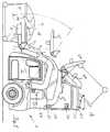
- the garbage collection vehicle 1 shown in the drawingis provided with paired U-shaped curved lifting arms 2, the shorter legs behind the cab 3 of which are horizontal Transverse axis 4 are pivotally connected to the chassis of the refuse collection vehicle in a known manner.
- hydraulic pressure-piston cylinder unitsare provided on both sides of the chassis, the piston rods of which are articulated to the lifting arms and the cylinders of which are articulated to the chassis.
- Lever-like support pieces 5are pivotally mounted about a horizontal transverse axis connecting the longer legs of the lifting arms 2, at one end of which the piston rods 6 are articulated by hydraulic cylinders 7, which are articulated at point 8 to the longer legs of the lifting arms 2.
- the support pieces 5are designed as angle levers, the longer arms 9 forming tines of a fork which can be inserted into sleeve-like receiving pockets 10 which are fastened to the side walls of a waste container 11.
- the driverpivots the prongs 9 to the correct height and aligns them horizontally so that they can be inserted into the receiving pockets by the ancestors of the refuse collection vehicle 1 until stops provided on the prongs 9 12 hit the edge of the receiving pockets 10.
- the waste container 11is coupled in the manner described via the tines 9 to the lifting and tilting device, it can be raised and tilted by switching on the automatic system.
- the automatic systemconsists of a computer, not shown, to which signals are supplied from angle sensors, which are arranged in the region of the pivot axes 4, 15 and generate signals which correspond to the respective pivot angle of the lifting arms relative to the chassis and the tines 9 relative to the lifting arm 2 .
- the arithmetic unitthen controls the lifting arms 2 and the tines 9 based on a predetermined program via conventional control devices in such a way that their swiveling movements overlap to form a lifting and tilting movement, which initially keep the waste container 11 essentially horizontal and only tilt it when the opening released by the cover 16 is located above the filling opening 17.
- the lid 16is articulated to the tank pan via lateral links 17, which are articulated at point 18 to the lid and at point 19 to the tank pan.
- the links 17are provided with laterally cantilevered rollers 20 which, when emptied to open the lid, run onto upper edges 21 of the side walls of the pouring opening.
- the pouring openingopens into a receiving space 24, in which a reciprocating press plate 25 is arranged, which conveys the rubbish poured into the receiving space 24 through an opening into a garbage container, not shown, and compresses the latter.
- a controlis linked to the lift-tilt device, which moves the press plate 25 into the left position shown in FIG. 1, so that the largest possible space is available when the waste is poured into the receiving space.
- the lifting arms 2are provided with cam-like stops 28 which run on counter stops 29 of the refuse collection vehicle at the end of the swivel path. In this end position of the lifting arms 2 ′′, the prongs 9 ′′ ′′ are pivoted even further in order to ensure that the waste container 11 is completely emptied.
- a CCD camera 30is arranged in the side wall of the bulk room, which allows the driver to monitor whether the container is completely emptied via a monitor arranged in the cab. Once this has been done, the driver can acknowledge the emptying via a switch, so that the garbage container is then set down again automatically.
- the driverobserves that the container is not completely emptied, he can operate the automatic control via a switch in such a way that the tines swing the garbage container back and forth until it is completely emptied.
- FIG. 2differs from that of FIG. 1 in that the axis 35 rigidly connecting the support pieces 5 carries one or more receiving claws 36 arranged next to one another, which engage in complementary receiving pockets 37 which in the upper edge region of the front of the tub Waste bins 38 are arranged.
- the driverdrives the garbage collection vehicle 1 to the container 38 to such an extent that he can couple the receiving claws 36 to the receiving pockets 37 by manually operating the control devices of the lifting arms and the supporting pieces 5. Once the coupling engagement has been established, the driver can operate the automatic control of the lifting and tilting device so that the waste container 28 is tilted in the desired manner.
- An additional switching deviceis provided for driving the refuse collection vehicle, which first swivels the tines or claws up and then moves them together with the lifting arms in the direction of the pouring opening.
Landscapes
- Engineering & Computer Science (AREA)
- Mechanical Engineering (AREA)
- Refuse-Collection Vehicles (AREA)
- Refuse Collection And Transfer (AREA)
Abstract
Description
Translated fromGermanDie Erfindung betrifft ein Müllsammelfahrzeug mit einer Hub-Kipp-Vorrichtung zur Aufnahme und zum Entleeren von Müllbehältern in eine Einschüttöffnung eines Sammelbehälters oder eines mit einer Förder- und Preßeinrichtung versehenen Aufnahmeraums, die aus mindestens einem schwenkbar mit dem Müllsammelfahrzeug verbundenen Hubarm und aus mindestens einer an diesem angelenkten Aufnahmeklaue oder Zinken aufweisenden Aufnahmegabel besteht, die über Druckmittelkolbenzylindereinheiten mit Zugehörigen Steuereinrichtungen verschwenkbar sind. Ein Müllsammelfahrzeug mit einer Hub-Kipp-Vorrichtung dieser Art ist beispielsweise aus der US-PS 43 49 305 bekannt. Um mit dieser Hub-KippVorrichtung angekuppelte Müllbehälter anzuheben und über Kopf in die Einschüttöffnung des hinter dem Führerhaus befindlichen Sammelbehälters zu entleeren, ist es erforderlich, die Hydraulikzylinder des Hubarms und der gelenkig mit diesem verbundenen Aufnahmegabel derart zu steuern, daß der angekuppelte Müllbehälter im wesentlichen waagrecht angehoben und möglichst lange in einer waagrechten Stellung gehalten und erst verkippt wird, wenn sich dessen von dessen Deckel freigegebene Öffnung oberhalb der Einschüttöffnung befindet, so daß aus dem Müllbehälter vorzeitig kein Müll herausfallen kann, der die Umgebung verschmutzen könnte. Eine derartige Steuerung der beiden Hydraulikzylinder bzw. Hydraulikzylinderpaare von Hand durch den Fahrer des Müllsammelfahrzeugs oder eine andere Bedienungsperson ist jedoch außerordentlich schwierig und erfordert erhebliches Geschick, zumal der zu hebende und zu verkippende Müllbehälter den letzten Teil seines Hubkippweges in einem Bereich durchführt, der von dem Fahrer nicht einsehbar ist. Bei dem bekannten Müllsammelfahrzeug kann es daher vorkommen, daß Müll aus dem zu entleerenden Müllbehälter bereits herausfällt, bevor sich dessen Öffnung oberhalb der Einschüttöffnung befindet, so daß Müll in die Umgebung oder auf das Müllfahrzeug und von diesem auf die Straße fallen kann.The invention relates to a refuse collection vehicle with a lifting and tilting device for receiving and emptying refuse containers into a pouring opening of a collection container or a receiving space provided with a conveying and pressing device, which consists of at least one lifting arm pivotably connected to the refuse collection vehicle and at least one this articulated receiving claw or prongs having receiving fork, which can be pivoted via pressure medium piston cylinder units with associated control devices. A refuse collection vehicle with a lifting and tipping device of this type is known, for example, from US Pat. No. 4,349,305. In order to lift the garbage containers coupled with this lifting and tilting device and to empty them overhead into the pouring opening of the collecting container located behind the driver's cab, it is necessary to control the hydraulic cylinders of the lifting arm and the articulated connecting fork in such a way that the coupled garbage container is essentially horizontal raised and held in a horizontal position for as long as possible and is not tilted until the opening of the cover of which is released is located above the pouring opening, so that no garbage can fall out of the garbage container prematurely and could pollute the surroundings. However, such control of the two hydraulic cylinders or hydraulic cylinder pairs by hand by the driver of the refuse collection vehicle or another operator is extremely difficult and requires considerable skill, especially since the refuse container to be lifted and tilted executes the last part of its lifting and tilting path in an area which is separated from the Driver is not visible. In the known garbage collection vehicle it can therefore happen that garbage already falls out of the garbage container to be emptied before its opening is above the pouring opening, so that garbage can fall into the environment or onto the garbage vehicle and from there onto the street.
Bei einer aus der EP-OS 163 859 bekannten Hub-Kipp-Vorrichtung für ein Müllsammelfahrzeug sind nur die Hubarme mit diesen verschwenkenden Hydraulikzylindern versehen und die an die Hubarme angelenkte Aufnahmeklaue wird über ein an den Hubarm und das Müllsammelfahrzeug angelenktes Lenker-Hebel-System in der Weise verschwenkt, daß der angekuppelte Müllbehälter während des ersten Teils der Hubbewegung im wesentlichen waagrecht verbleibt und erst im Endbereich der Hub-Kipp-Bewegung oberhalb der Einschüttöffnung beschleunigt verkippt wird. Diese Zwangssteuerung der Aufnahmeklaue durch ein Lenker-Hebel-System ist jedoch sehr aufwendig und trägt auch nicht dem Erfordernis Rechnung, daß es Betriebsfälle gibt, in denen eine Hub-Kipp-Bewegung mit anderer Charakteristik erwünscht ist.In a lifting and tilting device for a refuse collection vehicle known from EP-OS 163 859, only the lifting arms are provided with these pivoting hydraulic cylinders and the receiving claw articulated to the lifting arms is moved in via a handlebar lever system articulated to the lifting arm and the refuse collection vehicle pivoted in such a way that the coupled waste container remains essentially horizontal during the first part of the lifting movement and is only acceleratedly tilted above the pouring opening in the end region of the lifting-tilting movement. However, this forced control of the receiving claw by a handlebar-lever system is very complex and does not take into account the requirement that there are operating cases in which a stroke-tilt movement with a different characteristic is desired.
Aufgabe der Erfindung ist es daher, ein Müllsammelfahrzeug der eingangs angegebenen Art zu schaffen, bei dem sichergestellt ist, daß sich mit dessen Hub-Kipp-Vorrichtung an diese angekuppelte Müllbehälter in der Weise entleeren lassen, daß diese erst oberhalb der Einschüttöffnung soweit verkippt werden, daß der Müll aus deren Öffnungen herausfällt.The object of the invention is therefore to provide a refuse collection vehicle of the type specified at the outset, in which it is ensured that with its lifting-tilting device it is possible to empty refuse containers coupled to them in such a way that they are only tilted so far above the pouring opening, that the garbage falls out of their openings.
Erfindungsgemäß wird diese Aufgabe bei einem Müllsammelfahrzeug der gattungsgemäßen Art dadurch gelöst, daß der Hubarm und die Aufnahmeklaue o.dgl. mit Winkelgebern versehen sind, die entsprechend dem jeweiligen Schwenkwinkel zwischen dem Hubarm und dem Müllsammelfahrzeug sowie der Aufnahmeklaue o.dgl. und dem Hubarm Signale erzeugen, die einem Rechner zugeführt werden, der wahlweise die Steuerventile der Druckmittelkolbenzylindereinheiten derart steuert, daß diese einen an die Aufnahmeklaue angekuppelten Müllbehälter über einen vorbestimmten Teil des Hubweges im wesentlichen waagrecht führen und diesen erst im Endbereich des Hubweges zur Entleerung in die Einschüttöffnung verschwenken. Bei dem erfindungsgemäßen Müllsammelfahrzeug ist die Entleerung der Müllbehälter wesentlich vereinfacht, wobei zugleich sichergestellt ist, daß Müll nicht neben die Einschüttöffnung fällt, weil die Hub-Kipp-Vorrichtung mit einer automatisierten Zwangssteuerung versehen ist, die Fehlbedienungen durch den Fahrer oder das Bedienungspersonal ausschließt. Um einen zu entleerenden Müllbehälter zu verkippen, ist es lediglich erforderlich, daß eine Bedienungsperson oder der Fahrer den bereitgestellten Müllbehälter an die Aufnahmeklaue oder die Aufnahmegabel ankuppelt, was in üblicher Weise durch Handsteuerung und evtl. Verfahren des Müllsammelfahrzeugs geschieht. Ist der zu entleerende Müllbehälter an die Aufnahmeklaue oder die Aufnahmegabel angekuppelt, kann der Fahrer oder die Bedienungsperson die Automatik betätigen, so daß der Hub-Kipp-Vorgang rechnergesteuert erfolgt.According to the invention, this object is achieved in a refuse collection vehicle of the generic type in that the lifting arm and the receiving claw or the like. are provided with angle encoders or the like according to the respective swivel angle between the lifting arm and the refuse collection vehicle and the pick-up claw. and generate the lifting arm signals which are fed to a computer which optionally controls the control valves of the pressure piston cylinder units in such a way that they guide a garbage container coupled to the receiving claw essentially horizontally over a predetermined part of the lifting path and only in the end region of the lifting path for emptying into the Swivel the pouring opening. In the refuse collection vehicle according to the invention, the emptying of the refuse containers is considerably simplified, while at the same time ensuring that refuse does not fall next to the pouring opening, because the lifting and tilting device is provided with an automated positive control system which prevents incorrect operation by the driver or the operating personnel. In order to tilt a waste container to be emptied, it is only necessary for an operator or the driver to couple the waste container provided to the receiving claw or the receiving fork, which is done in the usual way by manual control and possibly methods of the waste collection vehicle. If the waste container to be emptied is coupled to the receiving claw or the receiving fork, the driver or the operator can operate the automatic system, so that the lifting and tilting process is computer-controlled.
Um die angekuppelten Müllbehälter automatisch verkippen zu können, ist es erforderlich, daß der zentralen Rechnereinheit die jeweiligen Winkelstellungen des Hubarms und der Aufnahmeklaue oder der Aufnahmegabel gemeldet werden, was durch Winkelgeber bekannter Art erfolgt. Die Winkelgeber melden durch Analoge oder digitale Signale die jeweilige Winkelstellung des Hubarms oder der Aufnahmeklaue o.dgl., aus denen der Rechner dann aufgrund eines vorgegebenen Programms die einander zugeordneten Winkelstellungen über den gesamten Hub-Kipp-Weg errechnet und entsprechend über bekannte Steuereinrichtungen und Magnetventile die Druckmittelkolbenzylindereinheiten steuert. Sobald der Behälter entleert worden ist, durchfährt die Automatik zum Absetzen des Behälters rückwärts die Hub-Kipp-Bewegung. Da der Behälter jedoch entleert ist und aus diesem kein Müll mehr herausfallen kann, kann beim Absetzen ein anderer Weg gewählt werden als der zum Entleeren der gefüllten Behälter erforderlich ist.In order to be able to automatically tilt the coupled garbage containers, it is necessary for the central computer unit to be informed of the respective angular positions of the lifting arm and of the receiving claw or the receiving fork, which is done by known angle encoders. The angle encoders report the respective angular position of the lifting arm or the pick-up claw or the like by means of analog or digital signals, from which the computer then assigns the assigned to one another on the basis of a predetermined program Calculates angular positions over the entire stroke-tilt path and controls the pressure medium piston cylinder units accordingly using known control devices and solenoid valves. As soon as the container has been emptied, the automatic system for moving the container backwards performs the lift-tilt movement. However, since the container is emptied and no more garbage can fall out of it, a different route can be selected when setting down than is required to empty the filled container.
Zusätzlich kann die Automatik mit einer Steuereinrichtung versehen sein, die das Durchfahren von Teilen der Hub-Kipp-Bewegung gestattet. Dies kann beispielsweise erforderlich sein, wenn der Fahrer oder die Bedienungsperson feststellt, daß der verkippte Behälter noch nicht vollständig entleert ist, so daß er zumindest den letzten Teil der Hub-Kipp-Bewegung zum Entleeren des Behälters wiederholt.In addition, the automatic system can be provided with a control device which allows parts of the lifting and tilting movement to be passed through. This may be necessary, for example, if the driver or the operator determines that the tilted container has not yet been completely emptied, so that he repeats at least the last part of the lifting and tilting movement to empty the container.
Die erfindungsgemäße Hub-Kipp-Vorrichtung kann frontseitig an einem Müllsammelfahrzeug, seitlich von diesem oder aber auch an dessen Heckseite angeordnet sein.The lifting and tilting device according to the invention can be arranged on the front of a refuse collection vehicle, on the side of the latter or else on the rear side thereof.
Ausführungsbeispiele der Erfindung werden nachstehend anhand der Zeichnung näher erläutert. In dieser zeigt
- Fig. 1
- eine Seitenansicht des vorderen Teils eines Müllsammelfahrzeugs mit einer Aufnahmegabel versehenen Hub-Kipp-Vorrichtung und
- Fig. 2
- eine der Fig. 1 entsprechende Darstellung, bei der das Kupplungsorgan der Hub-Kipp-Vorrichtung aus einer Aufnahmeklaue besteht.
- Fig. 1
- a side view of the front part of a refuse collection vehicle with a lifting fork and lifting device
- Fig. 2
- a representation corresponding to FIG. 1, in which the coupling member of the lifting and tilting device consists of a receiving claw.
Das aus der Zeichnung ersichtliche Müllsammelfahrzeug 1 ist mit paarweise vorgesehenen U-förmig gekrümmten Hubarmen 2 versehen, deren kürzeren Schenkel hinter dem Fahrerhaus 3 um eine horizontale Querachse 4 schwenkbar an dem Chassis des Müllsammelfahrzeugs in bekannter Weise angelenkt sind. Zum Verschwenken der Hubarme 2 sind beidseits des Chassis nicht dargestellte hydraulische Druckmittelkolbenzylindereinheiten vorgesehen, deren Kolbenstangen an die Hubarme und deren Zylinder an das Chassis angelenkt sind.The garbage collection vehicle 1 shown in the drawing is provided with paired U-shaped curved lifting arms 2, the shorter legs behind the cab 3 of which are horizontal Transverse axis 4 are pivotally connected to the chassis of the refuse collection vehicle in a known manner. To pivot the lifting arms 2, hydraulic pressure-piston cylinder units, not shown, are provided on both sides of the chassis, the piston rods of which are articulated to the lifting arms and the cylinders of which are articulated to the chassis.
Um eine die längeren Schenkel der Hubarme 2 verbindende horizontale Querachse sind hebelartige Tragstücke 5 schwenkbar gelagert, an deren einen Enden die Kolbenstangen 6 von Hydraulikzylindern 7 angelenkt sind, die gelenkig im Punkt 8 mit den längeren Schenkeln der Hubarme 2 verbunden sind. Die Tragstücke 5 sind als Winkelhebel ausgebildet, wobei die längeren Arme 9 Zinken einer Gabel bilden, die in manschettenartige Aufnahmetaschen 10 eingeführt werden können, die an seitlichen Wandungen eines Müllbehälters 11 befestigt sind. Zum Einführen der Zinken 9 der Aufnahmegabel in die Aufnahmetaschen 10 verschwenkt der Fahrer die Zinken 9 in die richtige Höhe und richtet diese waagrecht aus, so daß sie durch Vorfahren des Müllsammelfahrzeugs 1 in die Aufnahmetaschen soweit eingeführt werden können, bis an den Zinken 9 vorgesehene Anschläge 12 an den Rand der Aufnahmetaschen 10 anstoßen. Sobald der Müllbehälter 11 in der beschriebenen Weise über die Zinken 9 an die Hub-Kipp-Vorrichtung angekuppelt ist, kann dieser durch Einschalten der Automatik angehoben und verkippt werden.Lever-like support pieces 5 are pivotally mounted about a horizontal transverse axis connecting the longer legs of the lifting arms 2, at one end of which the piston rods 6 are articulated by hydraulic cylinders 7, which are articulated at point 8 to the longer legs of the lifting arms 2. The support pieces 5 are designed as angle levers, the
Die Automatik besteht aus einem nicht dargestellten Rechner, dem von Winkelgebern Signale zugeführt werden, die im Bereich der Schwenkachsen 4, 15 angeordnet sind und Signale erzeugen, die dem jeweiligen Schwenkwinkel der Hubarme relativ zu dem Chassis und der Zinken 9 relativ zu dem Hubarm 2 entsprechen. Die Recheneinheit steuert sodann aufgrund eines vorgegebenen Programms über übliche Steuereinrichtungen die Hubarme 2 und die Zinken 9 in der Weise, daß sich deren Schwenkbewegungen zu einer Hub-Kipp-Bewegung überlagern, die den Müllbehälter 11 im wesentlichen zunächst waagrecht halten und diesen erst verkippen, wenn sich dessen von dem Deckel 16 freigegebene Öffnung oberhalb der Einfüllöffnung 17 befindet.The automatic system consists of a computer, not shown, to which signals are supplied from angle sensors, which are arranged in the region of the pivot axes 4, 15 and generate signals which correspond to the respective pivot angle of the lifting arms relative to the chassis and the
Aus Fig. 1 sind einzelne Zwischenstellungen 9', 9,' und 9''' der Zinken während der Hub-Kipp-Bewegung ersichtlich.From Fig. 1 individual
Der Deckel 16 ist über seitliche Lenker 17, die gelenkig in dem Punkt 18 mit dem Deckel und in dem Punkt 19 mit der Behälterwanne verbunden sind, an die Behälterwanne angelenkt. Die Lenker 17 sind mit seitlich auskragenden Rollen 20 versehen, die bei dem Entleeren zur Öffnung des Deckels auf obere Ränder 21 der seitlichen Wandungen der Einschüttöffnung auflaufen.The lid 16 is articulated to the tank pan via lateral links 17, which are articulated at
Aus der Stellung der Zinken 9, 9', 9'', 9''' in Fig. 1 ist ersichtlich, daß der Behälter während eines Anhebens zunächst waagrecht gehalten wird und daß dessen Kippbewegung erst dann eingeleitet wird, wenn dieser sich oberhalb der Einschüttöffnung befindet, so daß herausfallender Abfall sicher in die Einschüttöffnung verkippt wird.From the position of the
Die Einschüttöffnung mündet in einen Aufnahmeraum 24, in dem ein hin- und herverfahrbarer Preßschild 25 angeordnet ist, der den in den Aufnahmeraum 24 eingeschütteten Müll durch eine Öffnung in einen nicht dargestellten Müllbehälter fördert und diesen in diesem verdichtet. Mit der Hub-Kipp-Vorrichtung ist eine Steuerung verknüpft, die den Preßschild 25 in die aus Fig. 1 ersichtliche linke Stellung verfährt, so daß beim Einschütten des Mülls in den Aufnahmeraum der größtmögliche Raum zur Verfügung steht.The pouring opening opens into a
Die Hubarme 2 sind mit nockenartigen Anschlägen 28 versehen, die am Ende des Schwenkweges auf Gegenanschläge 29 des Müllsammelfahrzeugs laufen. In dieser Endstellung der Hubarme 2'' werden die Zinken 9''' noch weiter verschwenkt, um eine vollständige Entleerung des Müllbehälters 11 sicherzustellen.The lifting arms 2 are provided with cam-like stops 28 which run on counter stops 29 of the refuse collection vehicle at the end of the swivel path. In this end position of the lifting arms 2 ″, the
In der Seitenwand des Schüttraums ist eine CCD-Kamera 30 angeordnet, die dem Fahrer über einen im Fahrerhaus angeordneten Monitor Beobachtung erlaubt, ob der Behälter vollständig entleert ist. Ist dies geschehen, kann der Fahrer die Entleerung über einen Schalter quittieren, so daß dann über die Automatik der Müllbehälter wieder abgesetzt wird.A
Sollte der Fahrer beobachten, daß der Behälter nicht vollständig entleert ist, kann er über einen Schalter die automatische Steuerung in der Weise betätigen, daß die Zinken den Müllbehälter bis zur vollständigen Entleerung hin- und herverschwenken.If the driver observes that the container is not completely emptied, he can operate the automatic control via a switch in such a way that the tines swing the garbage container back and forth until it is completely emptied.
Das Ausführungsbeispiel nach Fig. 2 unterscheidet sich von dem nach Fig. 1 dadurch, daß die die Tragstücke 5 starr verbindende Achse 35 eine oder mehrere nebeneinander angeordnete Aufnahmeklauen 36 trägt, die in komplementäre Aufnahmetaschen 37 greifen, die im oberen Randbereich der Vorderseite der Wanne der Müllbehälter 38 angeordnet sind. Zum Ankuppeln der Müllbehälter 38 an die Aufnahmeklauen 36 fährt der Fahrer das Müllsammelfahrzeug 1 an den Behälter 38 soweit heran, daß er durch Handbetätigung der Steuereinrichtungen der Hubarme und der Tragstücke 5 die Aufnahmeklauen 36 mit den Aufnahmetaschen 37 kuppeln kann. Ist der kuppelnde Eingriff hergestellt, kann der Fahrer die automatische Steuerung der Hub-Kipp-Vorrichtung betätigen, so daß das Verkippen des Müllbehälters 28 in der gewünschten Weise erfolgt.The embodiment of FIG. 2 differs from that of FIG. 1 in that the axis 35 rigidly connecting the support pieces 5 carries one or more receiving
Für den Fahrbetrieb des Müllsammelfahrzeugs ist eine zusätzliche Schalteinrichtung vorgesehen, die zunächst die Zinken oder Klauen hochschwenkt und diese zusammen sodann mit den Hubarmen in Richtung der Einschüttöffnung verfährt.An additional switching device is provided for driving the refuse collection vehicle, which first swivels the tines or claws up and then moves them together with the lifting arms in the direction of the pouring opening.
Claims (2)
Translated fromGermandadurch gekennzeichnet,
daß der Hubarm (2) und die Aufnahmeklaue (36) o.dgl. mit Winkelgebern versehen sind, die entsprechend dem jeweiligen Schwenkwinkel zwischen dem Hubarm (2) und dem Müllsammelfahrzeug (1) sowie der Aufnahmeklaue (36) und dem Hubarm (2) Signale erzeugen, die einem Rechner zugeführt werden, der wahlweise die Steuerventile der Druckmittelkolbenzylindereinheiten derart steuert, daß diese einen an die Aufnahmeklaue o.dgl. angekuppelten Müllbehälter (11) über einen vorbestimmten Teil des Hubweges im wesentlichen waagrecht führen und diesen erst im Endbereich des Hubweges zur Entleerung in die Einschüttöffnung verschwenken.Refuse collection vehicle with a lifting and tipping device for receiving and emptying refuse containers into a pouring opening of a collection container or a receiving space provided with a conveying and pressing device, which consists of at least one lifting arm pivotally connected to the refuse collection vehicle and at least one pick-up claw articulated thereon or consists of a fork with tines that can be pivoted via pressure medium piston cylinder units with associated control devices,
characterized,
that the lifting arm (2) and the receiving claw (36) or the like. are provided with angle sensors which correspond to the respective swivel angle between the lifting arm (2) and the refuse collection vehicle (1) and the receiving claw (36) and the lifting arm (2) generate signals which are fed to a computer, which optionally controls the control valves of the pressure piston cylinder units in such a way that these or the like on the receiving claw. guide the coupled waste container (11) substantially horizontally over a predetermined part of the stroke and pivot it only in the end region of the stroke for emptying into the pouring opening.
Applications Claiming Priority (2)
| Application Number | Priority Date | Filing Date | Title |
|---|---|---|---|
| DE4102064 | 1991-01-24 | ||
| DE4102064ADE4102064A1 (en) | 1991-01-24 | 1991-01-24 | WASTE COLLECTING VEHICLE WITH A LIFTING AND TILTING DEVICE FOR RECEIVING AND EMPTYING WASTE CONTAINERS IN A TUBE OPENING |
Publications (2)
| Publication Number | Publication Date |
|---|---|
| EP0496302A1true EP0496302A1 (en) | 1992-07-29 |
| EP0496302B1 EP0496302B1 (en) | 1994-06-29 |
Family
ID=6423625
Family Applications (1)
| Application Number | Title | Priority Date | Filing Date |
|---|---|---|---|
| EP92100773AExpired - LifetimeEP0496302B1 (en) | 1991-01-24 | 1992-01-17 | Refuse vehicle with a lifting and dumping device for unloading refuse containers into a receiving chute |
Country Status (4)
| Country | Link |
|---|---|
| EP (1) | EP0496302B1 (en) |
| AT (1) | ATE107904T1 (en) |
| DE (2) | DE4102064A1 (en) |
| ES (1) | ES2056668T3 (en) |
Cited By (15)
| Publication number | Priority date | Publication date | Assignee | Title |
|---|---|---|---|---|
| US5474413A (en)* | 1992-02-12 | 1995-12-12 | Georg; Edgar | Vehicle for collecting and transporting waste materials |
| EP0728685A1 (en)* | 1995-02-23 | 1996-08-28 | Max Aicher GmbH Entsorgungstechnik | Lever mechanism actuated by two hydraulic piston-cylinders |
| US5741107A (en)* | 1994-05-13 | 1998-04-21 | Georg; Edgar | Refuse collection vehicle |
| US6059511A (en)* | 1995-03-07 | 2000-05-09 | Toccoa Metal Technologies, Inc. | Residential front loading refuse collection vehicle |
| US6123497A (en)* | 1993-09-09 | 2000-09-26 | Galion Solid Waste Equipment Co., Inc. | Automated refuse vehicle |
| WO2004052756A1 (en)* | 2002-12-09 | 2004-06-24 | Oshkosh Truck Corporation | Refuse vehicle control system and method |
| US7725225B2 (en) | 2002-12-09 | 2010-05-25 | Oshkosh Corporation | Refuse vehicle control system and method with footboard |
| EP2305578A1 (en)* | 2009-10-02 | 2011-04-06 | Compagnie Plastic Omnium | Device for collecting waste such as a waste collection truck |
| ITPI20090139A1 (en)* | 2009-11-05 | 2011-05-06 | Cucini S R L Off | TILTING DEVICE FOR BOXES. |
| US8947531B2 (en) | 2006-06-19 | 2015-02-03 | Oshkosh Corporation | Vehicle diagnostics based on information communicated between vehicles |
| US9420203B2 (en) | 2006-06-19 | 2016-08-16 | Oshkosh Defense, Llc | Vision system for a vehicle |
| CN107472752A (en)* | 2017-09-21 | 2017-12-15 | 左勤 | A kind of categorized consumer waste is collected and the method and system of intelligence direct |
| US9845191B2 (en) | 2013-08-02 | 2017-12-19 | Oshkosh Corporation | Ejector track for refuse vehicle |
| WO2018053581A1 (en)* | 2016-09-20 | 2018-03-29 | Superior Pak Holdings Pty Ltd | Front load mobile compaction vehicle loading system |
| CN108978553A (en)* | 2018-08-06 | 2018-12-11 | 诸暨市艾峰自动化科技有限公司 | Automatic garbage collection equipment and automatic garbage collection method |
Families Citing this family (2)
| Publication number | Priority date | Publication date | Assignee | Title |
|---|---|---|---|---|
| US7729831B2 (en) | 1999-07-30 | 2010-06-01 | Oshkosh Corporation | Concrete placement vehicle control system and method |
| US7379797B2 (en) | 2001-01-31 | 2008-05-27 | Oshkosh Truck Corporation | System and method for braking in an electric vehicle |
Citations (2)
| Publication number | Priority date | Publication date | Assignee | Title |
|---|---|---|---|---|
| US4349305A (en)* | 1977-11-01 | 1982-09-14 | Dempster Systems Inc. | Lifting and dumping apparatus |
| EP0163859B1 (en)* | 1984-05-29 | 1989-11-29 | Edelhoff M.S.T.S. Gmbh | Refuse-collecting vehicle with an interchangeable collecting receptacle |
Family Cites Families (4)
| Publication number | Priority date | Publication date | Assignee | Title |
|---|---|---|---|---|
| US3827587A (en)* | 1969-07-31 | 1974-08-06 | Carrier Corp | Automatic self-leveling forks |
| DE3448135C2 (en)* | 1984-02-20 | 1988-09-15 | Zoeller-Kipper Gmbh, 6500 Mainz, De | Apparatus for emptying containers, especially refuse containers |
| DE8811472U1 (en)* | 1988-09-10 | 1988-10-27 | Alustahl Behälterbau GmbH & Co KG, 28816 Stuhr | Truck box body with a waste container transfer device |
| DE3903592A1 (en)* | 1989-02-07 | 1990-08-09 | Proteus Ges Fuer Datentechnik | Method and device for determining and allocating quantities of waste to be disposed of |
- 1991
- 1991-01-24DEDE4102064Apatent/DE4102064A1/ennot_activeWithdrawn
- 1992
- 1992-01-17EPEP92100773Apatent/EP0496302B1/ennot_activeExpired - Lifetime
- 1992-01-17DEDE59200255Tpatent/DE59200255D1/ennot_activeExpired - Fee Related
- 1992-01-17ATAT92100773Tpatent/ATE107904T1/ennot_activeIP Right Cessation
- 1992-01-17ESES92100773Tpatent/ES2056668T3/ennot_activeExpired - Lifetime
Patent Citations (2)
| Publication number | Priority date | Publication date | Assignee | Title |
|---|---|---|---|---|
| US4349305A (en)* | 1977-11-01 | 1982-09-14 | Dempster Systems Inc. | Lifting and dumping apparatus |
| EP0163859B1 (en)* | 1984-05-29 | 1989-11-29 | Edelhoff M.S.T.S. Gmbh | Refuse-collecting vehicle with an interchangeable collecting receptacle |
Cited By (20)
| Publication number | Priority date | Publication date | Assignee | Title |
|---|---|---|---|---|
| EP0720957A1 (en)* | 1992-02-12 | 1996-07-10 | Edgar Georg | Vehicle for collecting and transporting refuse with a support for the pick-up device |
| US5474413A (en)* | 1992-02-12 | 1995-12-12 | Georg; Edgar | Vehicle for collecting and transporting waste materials |
| US6123497A (en)* | 1993-09-09 | 2000-09-26 | Galion Solid Waste Equipment Co., Inc. | Automated refuse vehicle |
| US5741107A (en)* | 1994-05-13 | 1998-04-21 | Georg; Edgar | Refuse collection vehicle |
| EP0728685A1 (en)* | 1995-02-23 | 1996-08-28 | Max Aicher GmbH Entsorgungstechnik | Lever mechanism actuated by two hydraulic piston-cylinders |
| US6059511A (en)* | 1995-03-07 | 2000-05-09 | Toccoa Metal Technologies, Inc. | Residential front loading refuse collection vehicle |
| US6158945A (en)* | 1995-03-07 | 2000-12-12 | Toccoa Metal Technologies, Inc. | Residential front loading refuse collection vehicle |
| WO2004052756A1 (en)* | 2002-12-09 | 2004-06-24 | Oshkosh Truck Corporation | Refuse vehicle control system and method |
| US7725225B2 (en) | 2002-12-09 | 2010-05-25 | Oshkosh Corporation | Refuse vehicle control system and method with footboard |
| US8947531B2 (en) | 2006-06-19 | 2015-02-03 | Oshkosh Corporation | Vehicle diagnostics based on information communicated between vehicles |
| US9420203B2 (en) | 2006-06-19 | 2016-08-16 | Oshkosh Defense, Llc | Vision system for a vehicle |
| FR2950871A1 (en)* | 2009-10-02 | 2011-04-08 | Plastic Omnium Cie | DEVICE FOR COLLECTING WASTE, SUCH AS A COLLECTION TRUCK |
| EP2305578A1 (en)* | 2009-10-02 | 2011-04-06 | Compagnie Plastic Omnium | Device for collecting waste such as a waste collection truck |
| EP2305578B1 (en) | 2009-10-02 | 2021-01-27 | SULO France | Device for collecting waste such as a waste collection truck |
| ITPI20090139A1 (en)* | 2009-11-05 | 2011-05-06 | Cucini S R L Off | TILTING DEVICE FOR BOXES. |
| US9845191B2 (en) | 2013-08-02 | 2017-12-19 | Oshkosh Corporation | Ejector track for refuse vehicle |
| WO2018053581A1 (en)* | 2016-09-20 | 2018-03-29 | Superior Pak Holdings Pty Ltd | Front load mobile compaction vehicle loading system |
| CN107472752A (en)* | 2017-09-21 | 2017-12-15 | 左勤 | A kind of categorized consumer waste is collected and the method and system of intelligence direct |
| CN108978553A (en)* | 2018-08-06 | 2018-12-11 | 诸暨市艾峰自动化科技有限公司 | Automatic garbage collection equipment and automatic garbage collection method |
| CN108978553B (en)* | 2018-08-06 | 2024-04-05 | 南京卓鑫发科技有限公司 | Automatic garbage collection equipment and automatic garbage collection method |
Also Published As
| Publication number | Publication date |
|---|---|
| ES2056668T3 (en) | 1994-10-01 |
| DE4102064A1 (en) | 1992-08-13 |
| DE59200255D1 (en) | 1994-08-04 |
| ATE107904T1 (en) | 1994-07-15 |
| EP0496302B1 (en) | 1994-06-29 |
Similar Documents
| Publication | Publication Date | Title |
|---|---|---|
| EP0496302B1 (en) | Refuse vehicle with a lifting and dumping device for unloading refuse containers into a receiving chute | |
| EP0235784B1 (en) | Tipping mechanism for a refuse-collecting vehicle | |
| DD146929A5 (en) | LIFT-TILT OR TILTING DEVICE FOR DRAINING CONTAINERS OF DIFFERENT SIZE | |
| DE29520278U1 (en) | Container vehicle with loading device | |
| EP2292417B1 (en) | Channel baling press | |
| EP0295574B1 (en) | Refuse collection vehicle | |
| DE69502404T2 (en) | Device for picking up and emptying waste containers in a refuse collection vehicle | |
| DE3210338C2 (en) | ||
| EP0358893A1 (en) | Dumping device for emptying dust bins in refuse-collecting vehicles | |
| DE10042800A1 (en) | Refuse collection vehicle operates continually or intermittently, discharges by rear tipping and has a chassis with a main container and a secondary container hinged to it | |
| EP1321383B1 (en) | Refuse collection vehicle with grabbing means for refuse collection containers | |
| DE2444771A1 (en) | Material conveyor into collecting container - has compression and loading shovels guided downwards and rearwards on return stroke | |
| DE8811472U1 (en) | Truck box body with a waste container transfer device | |
| DE3304656C2 (en) | ||
| EP0786424B1 (en) | Lifting and tipping device with means for locking the trunnions of a refuse receptacle | |
| EP0763488B1 (en) | Refuse collection vehicle | |
| DE935118C (en) | Automatic loading device for garbage trucks | |
| DE2920835C2 (en) | Device for emptying garbage containers into a garbage truck | |
| DE4142307A1 (en) | Method for emptying dustbins into dustcart - involves vehicle arranged as side loader with bin picked up from initial position within vehicle side contour and pivoted horizontally to discharge contents | |
| DE2326812C3 (en) | Garbage truck with feed bunker and tiltable main collection container | |
| DE19516133B4 (en) | Device for emptying large refuse containers | |
| DE2645884A1 (en) | Motor transport and tilting vehicle - can lift and move a slag bucket, then turn it upside down for emptying | |
| DE20305903U1 (en) | Rubbish truck for collecting household rubbish has a cabin and a collecting area for the rubbish as well as a loading platform which moves about a vertical axle | |
| DE2264381C3 (en) | Garbage truck with garbage tube | |
| DE29915083U1 (en) | Refuse collection vehicle |
Legal Events
| Date | Code | Title | Description |
|---|---|---|---|
| PUAI | Public reference made under article 153(3) epc to a published international application that has entered the european phase | Free format text:ORIGINAL CODE: 0009012 | |
| 17P | Request for examination filed | Effective date:19920527 | |
| AK | Designated contracting states | Kind code of ref document:A1 Designated state(s):AT BE CH DE DK ES FR GB GR IT LI LU NL PT SE | |
| 17Q | First examination report despatched | Effective date:19930525 | |
| GRAA | (expected) grant | Free format text:ORIGINAL CODE: 0009210 | |
| AK | Designated contracting states | Kind code of ref document:B1 Designated state(s):AT BE CH DE DK ES FR GB GR IT LI LU NL PT SE | |
| PG25 | Lapsed in a contracting state [announced via postgrant information from national office to epo] | Ref country code:GR Free format text:LAPSE BECAUSE OF FAILURE TO SUBMIT A TRANSLATION OF THE DESCRIPTION OR TO PAY THE FEE WITHIN THE PRESCRIBED TIME-LIMIT Effective date:19940629 Ref country code:DK Effective date:19940629 | |
| REF | Corresponds to: | Ref document number:107904 Country of ref document:AT Date of ref document:19940715 Kind code of ref document:T | |
| REF | Corresponds to: | Ref document number:59200255 Country of ref document:DE Date of ref document:19940804 | |
| GBT | Gb: translation of ep patent filed (gb section 77(6)(a)/1977) | Effective date:19940707 | |
| ET | Fr: translation filed | ||
| ITF | It: translation for a ep patent filed | ||
| PG25 | Lapsed in a contracting state [announced via postgrant information from national office to epo] | Ref country code:SE Effective date:19940929 Ref country code:PT Effective date:19940929 | |
| REG | Reference to a national code | Ref country code:ES Ref legal event code:FG2A Ref document number:2056668 Country of ref document:ES Kind code of ref document:T3 | |
| PG25 | Lapsed in a contracting state [announced via postgrant information from national office to epo] | Ref country code:AT Effective date:19950117 | |
| PG25 | Lapsed in a contracting state [announced via postgrant information from national office to epo] | Ref country code:LU Free format text:LAPSE BECAUSE OF NON-PAYMENT OF DUE FEES Effective date:19950131 Ref country code:LI Effective date:19950131 Ref country code:CH Effective date:19950131 | |
| PLBE | No opposition filed within time limit | Free format text:ORIGINAL CODE: 0009261 | |
| STAA | Information on the status of an ep patent application or granted ep patent | Free format text:STATUS: NO OPPOSITION FILED WITHIN TIME LIMIT | |
| 26N | No opposition filed | ||
| REG | Reference to a national code | Ref country code:CH Ref legal event code:PL | |
| PGFP | Annual fee paid to national office [announced via postgrant information from national office to epo] | Ref country code:DE Payment date:20011016 Year of fee payment:11 | |
| PGFP | Annual fee paid to national office [announced via postgrant information from national office to epo] | Ref country code:NL Payment date:20011220 Year of fee payment:11 | |
| PGFP | Annual fee paid to national office [announced via postgrant information from national office to epo] | Ref country code:ES Payment date:20011227 Year of fee payment:11 | |
| REG | Reference to a national code | Ref country code:GB Ref legal event code:IF02 | |
| PGFP | Annual fee paid to national office [announced via postgrant information from national office to epo] | Ref country code:GB Payment date:20020102 Year of fee payment:11 | |
| PGFP | Annual fee paid to national office [announced via postgrant information from national office to epo] | Ref country code:BE Payment date:20020125 Year of fee payment:11 | |
| PGFP | Annual fee paid to national office [announced via postgrant information from national office to epo] | Ref country code:FR Payment date:20020129 Year of fee payment:11 | |
| PG25 | Lapsed in a contracting state [announced via postgrant information from national office to epo] | Ref country code:GB Free format text:LAPSE BECAUSE OF NON-PAYMENT OF DUE FEES Effective date:20030117 | |
| PG25 | Lapsed in a contracting state [announced via postgrant information from national office to epo] | Ref country code:ES Free format text:LAPSE BECAUSE OF NON-PAYMENT OF DUE FEES Effective date:20030118 | |
| PG25 | Lapsed in a contracting state [announced via postgrant information from national office to epo] | Ref country code:BE Free format text:LAPSE BECAUSE OF NON-PAYMENT OF DUE FEES Effective date:20030131 | |
| PG25 | Lapsed in a contracting state [announced via postgrant information from national office to epo] | Ref country code:NL Free format text:LAPSE BECAUSE OF NON-PAYMENT OF DUE FEES Effective date:20030801 Ref country code:DE Free format text:LAPSE BECAUSE OF NON-PAYMENT OF DUE FEES Effective date:20030801 | |
| GBPC | Gb: european patent ceased through non-payment of renewal fee | ||
| PG25 | Lapsed in a contracting state [announced via postgrant information from national office to epo] | Ref country code:FR Free format text:LAPSE BECAUSE OF NON-PAYMENT OF DUE FEES Effective date:20030930 | |
| NLV4 | Nl: lapsed or anulled due to non-payment of the annual fee | Effective date:20030801 | |
| REG | Reference to a national code | Ref country code:FR Ref legal event code:ST | |
| REG | Reference to a national code | Ref country code:ES Ref legal event code:FD2A Effective date:20030118 | |
| PG25 | Lapsed in a contracting state [announced via postgrant information from national office to epo] | Ref country code:IT Free format text:LAPSE BECAUSE OF NON-PAYMENT OF DUE FEES;WARNING: LAPSES OF ITALIAN PATENTS WITH EFFECTIVE DATE BEFORE 2007 MAY HAVE OCCURRED AT ANY TIME BEFORE 2007. THE CORRECT EFFECTIVE DATE MAY BE DIFFERENT FROM THE ONE RECORDED. Effective date:20050117 |