EP0494815A1 - Motor vehicles traffic measuring system - Google Patents
Motor vehicles traffic measuring systemDownload PDFInfo
- Publication number
- EP0494815A1 EP0494815A1EP92400027AEP92400027AEP0494815A1EP 0494815 A1EP0494815 A1EP 0494815A1EP 92400027 AEP92400027 AEP 92400027AEP 92400027 AEP92400027 AEP 92400027AEP 0494815 A1EP0494815 A1EP 0494815A1
- Authority
- EP
- European Patent Office
- Prior art keywords
- vehicles
- camera
- trigger detector
- infrared
- projector
- Prior art date
- Legal status (The legal status is an assumption and is not a legal conclusion. Google has not performed a legal analysis and makes no representation as to the accuracy of the status listed.)
- Granted
Links
- 238000012545processingMethods0.000claimsabstractdescription8
- 238000010191image analysisMethods0.000claimsabstractdescription4
- 238000005259measurementMethods0.000claimsdescription15
- 230000001960triggered effectEffects0.000claimsdescription2
- 238000010586diagramMethods0.000description6
- 238000001514detection methodMethods0.000description5
- 230000010354integrationEffects0.000description3
- 230000006870functionEffects0.000description2
- 230000005540biological transmissionEffects0.000description1
- 230000015572biosynthetic processEffects0.000description1
- 238000004891communicationMethods0.000description1
- 238000005755formation reactionMethods0.000description1
- 238000000034methodMethods0.000description1
- 230000000422nocturnal effectEffects0.000description1
- 230000003287optical effectEffects0.000description1
- 230000008520organizationEffects0.000description1
- 239000000700radioactive tracerSubstances0.000description1
- 230000001360synchronised effectEffects0.000description1
- 238000012549trainingMethods0.000description1
- 238000012546transferMethods0.000description1
Images


Classifications
- G—PHYSICS
- G08—SIGNALLING
- G08G—TRAFFIC CONTROL SYSTEMS
- G08G1/00—Traffic control systems for road vehicles
- G08G1/01—Detecting movement of traffic to be counted or controlled
- G08G1/04—Detecting movement of traffic to be counted or controlled using optical or ultrasonic detectors
- G—PHYSICS
- G08—SIGNALLING
- G08G—TRAFFIC CONTROL SYSTEMS
- G08G1/00—Traffic control systems for road vehicles
- G08G1/01—Detecting movement of traffic to be counted or controlled
- G08G1/052—Detecting movement of traffic to be counted or controlled with provision for determining speed or overspeed
Definitions
- the present inventionrelates to a system for measuring the traffic of motor vehicles on a traffic lane, comprising at least two measuring stations, spaced along said lane.
- the present inventionaims to achieve a device for measuring automobile traffic requiring no special equipment on motor vehicles.
- each measurement stationcomprises a trigger detector operating by transmission / reception of a beam infra-red laser and providing a trigger signal for each reference vehicle, an infra-red light projector directing a beam on the vehicles in circulation and a camera whose shooting is triggered by the signal of the trigger detector and providing a video signal to an image analysis and data processing system that analyzes vehicle license plates to identify them and calculates vehicle travel time.
- the measuring stationsare located in height relative to the roadway, at the edge or above the track.
- the projectorconsists of a discharge lamp associated with a reflector and an infrared filter, an electronic control unit and an electronic supply for the discharge lamp.
- the trigger detectoris constituted by a triangulation measurement system the transmitter of which is an infrared laser diode and the receiver of which is a photoelement associated with a lens fitted with an infrared filter and with a electronic detection of the signal received by reflection on the road or on vehicles.
- the systemcomprises means of synchronization between the lightning of the infrared projector, the shooting by the CCD camera, acquisition and computer processing of images and arrival of the vehicle in the field of the camera.
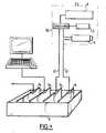
- the system according to the inventioncomprises two measuring stations A and B located along a traffic lane 1 and spaced apart from one another in the direction of traffic.
- Each stationcomprises a shooting head 2 situated in height relative to the track, on the edge or above this track, integrating or associated with an image processing system 8.
- Measuring stations A and Bare located high above the road, at the edge or above the track.
- Each shooting head 2comprises a trigger detector 3, a light projector 4, and a CCD camera 5.
- the trigger detector 3has the function of detecting each vehicle 9 in the flow of traffic and triggering a shooting. It is placed next to camera 5 and observes the way in the same way as the camera.
- the trigger detector 3 illustrated in FIG. 3is based on a distance measurement by telemetry, thanks to the emission of an infrared laser beam modulated in amplitude and the detection by appropriate optics and electronics of the beam reflected by the roadway or a vehicle.
- the trigger detector 3operates on a triangulation principle. It is constituted by an infrared laser emitter 31 giving a focused beam 36 and amplitude modulated and by a light receiver 32 receiving the reflected beam 37 on the vehicle 5. The axes of the beams 36 and 37 make a non-zero angle between them.
- the transmitter 31consists of a laser diode.
- the light receiver 32is constituted by a lens 33, associated with a filter 35 and by a detector 34 constituted by a photodiode with two sensitive surfaces 341 and 342.
- An electronicscontrols the laser diode and processes the signal coming from photodiode 34. Au rest, the reflected beam 37, reference 37 A in FIG.
- the light projector 4 illustrated in FIG. 4is of the infrared projector type. It comprises a discharge lamp 41 mounted on a support 42, a parabolic or spherical focusing reflector 43 and an infrared filter 44 associated with at least one lens.
- This projector 4emits a flash of light in the near infrared which is focused on the front of the vehicles by the reflector 43.
- This emission of lightis intended to compensate for a lack of light due to the nocturnal situations and the short time d integration of the measurement chain associated with the shooting head.
- the emitted poweris concentrated in space thanks to good focusing, and in time thanks to an impulse type emission. It also has the advantage of being almost completely invisible and therefore meets the criterion of discretion.
- the lampis controlled by an electronic assembly comprising a power electronics 45, a control electronics 46 and an interface electronics 47.
- the camera 5makes it possible to take the image of the front of the moving vehicles, detected by the trigger 3. Reading license plates requires precise image taking when the front of the vehicle is in the field of the camera.
- Camera 5is of the CCD type with electronic shutter. It has a low integration time and preferably works with frame transfer to obtain a better quality image.
- the integration timetime during which the image is formed on the CCD is low.
- the cameraincludes a mechanical or optical shutter or an equivalent electronic function.
- the video signal supplied by the camera 5is sent by a link 61 to an image acquisition card 71 included in a microcomputer 8.
- This card 71is composed of an analog-digital converter, of one or more memory plans for image storage and possibly specialized processors providing part of the processing on the card.
- the associated softwareincludes a specific software for recognition of the number plates, which provides (if possible) an alphanumeric character string representing the number plate and an operating software which ensures the course of all the operations of taking pictures, detection and reading the license plate, communicating with the other station (s), or measuring and storing journey time (and other traffic information: vehicle counting, hourly statistics, etc.)
- the projector 4, the detector 3 and the camera 5are synchronized by a synchronization card 72 mounted in the microcomputer and connected by a link 62 to a synchronization circuit 63 of the shooting head connected to the various elements 4, 3, 5.
- Other cards 73 and 74respectively allow the optional connection with a screen-keyboard interface and inter-station communication.
- the vehicleWhen the vehicle arrives near the station, it cuts off the infrared beam from the vehicle detector 3. The latter triggers the infra-red projector 4, the camera shoots 5 and acquires the image by the image analysis system. This identifies the vehicle by its registration number and enters the time of passage of the vehicle. It transmits this information to station B which stores it.
- Travel time measurement systemscan be implemented in a city no longer as a series of pairs of stations A and B but as a complete network.
- the stationscan be organized either in chain (figure. 6), each transmitting information to the next and receiving from the previous one, or in star (fig. 7) the information of each station being concentrated towards the same common system , or again any configuration associating these two modes of organization (fig. 8).
Landscapes
- Physics & Mathematics (AREA)
- General Physics & Mathematics (AREA)
- Traffic Control Systems (AREA)
Abstract
Translated fromFrenchDescription
Translated fromFrenchLa presente invention se rapporte à un système de mesure du trafic de véhicules automobiles sur une voie de circulation, comportant au moins deux postes de mesure, espacés le long de ladite voie.The present invention relates to a system for measuring the traffic of motor vehicles on a traffic lane, comprising at least two measuring stations, spaced along said lane.
On cherche à obtenir des informations sur la circulation des automobiles. Le temps mis par un vehicule pour parcourir un tronçon de voie urbaine ou routière est le principal élément qui définit la "fluidité du trafic".We are looking for information on automobile traffic. The time taken by a vehicle to travel a stretch of urban or road lane is the main element that defines "traffic flow".
Actuellement on mesure le débit d'une voie à l'aide d'un compteur de véhicules (boucle magnétique placée dans la chaussée).Currently we measure the flow of a lane using a vehicle counter (magnetic loop placed in the roadway).
Il a été imaginé d'équiper une flotte de véhicules (dits véhicules traceurs) d'un dispositif de mesure et d'un dispositif de transmission de données vers des balises installées aux carrefours. Un pourcentage significatif (5 à 10 %) du parc automobile doit être équipe pour obtenir des informations valides du système ce qui impose un investissement initial élevé.It has been imagined to equip a fleet of vehicles (so-called tracer vehicles) with a measuring device and a device for transmitting data to beacons installed at crossroads. A significant percentage (5 to 10%) of the vehicle fleet must be equipped to obtain valid information from the system, which requires a high initial investment.
La présente invention a pour but de réaliser un dispositif de mesure de la cirulation automobile ne nécessitant aucun équipement spécial sur les véhicules automobiles.The present invention aims to achieve a device for measuring automobile traffic requiring no special equipment on motor vehicles.
Le système de mesure de trafic de véhicules automobiles selon l'invention est caractérisé par le fait que chaque poste de mesure comprend un détecteur de déclenchement fonctionnant par émission/réception d'un faisceau laser infra-rouge et fournissant un signal de déclenchement pour chaque véhicule repère, un projecteur de lumière infra-rouge dirigeant un faisceau sur les véhicules en circulation et une caméra dont la prise de vue est déclenchée par le signal du détecteur de déclenchement et fournissant un signal vidéo à un système d'analyse d'images et de traitement des données qui analyse les plaques d'immatriculation des véhicules afin de les identifier et calcule le temps de parcours des véhicules .The motor vehicle traffic measurement system according to the invention is characterized in that each measurement station comprises a trigger detector operating by transmission / reception of a beam infra-red laser and providing a trigger signal for each reference vehicle, an infra-red light projector directing a beam on the vehicles in circulation and a camera whose shooting is triggered by the signal of the trigger detector and providing a video signal to an image analysis and data processing system that analyzes vehicle license plates to identify them and calculates vehicle travel time.
Selon une caractéristique, les postes de mesure sont situés en hauteur par rapport à la chaussée, au bord ou au-dessus de la voie.According to one characteristic, the measuring stations are located in height relative to the roadway, at the edge or above the track.
Selon une caractéristique, le projecteur est constitué d'une lampe à décharge associée à un réflecteur et à un filtre infra-rouge, d'une électronique de commande et d'une électronique d'alimentation de la lampe à décharge.According to one characteristic, the projector consists of a discharge lamp associated with a reflector and an infrared filter, an electronic control unit and an electronic supply for the discharge lamp.
Selon une caractéristique, le détecteur de déclenchement est constitué par un système de mesure à triangulation dont l'émetteur est une diode laser infra-rouge et dont le récepteur est un photoélément associe à un objectif muni d'un filtre infra-rouge et à une électronique de détection du signal reçu par réflexion sur la chaussée ou sur les véhicules.According to one characteristic, the trigger detector is constituted by a triangulation measurement system the transmitter of which is an infrared laser diode and the receiver of which is a photoelement associated with a lens fitted with an infrared filter and with a electronic detection of the signal received by reflection on the road or on vehicles.
Selon une caractéristique, le système comporte des moyens de synchronisation entre l'éclair du projecteur infra-rouge, la prise de vue par la caméra CCD, l'acquisition et le traitement informatique des images et l'arrivée du véhicule dans le champ de la caméra.According to one characteristic, the system comprises means of synchronization between the lightning of the infrared projector, the shooting by the CCD camera, acquisition and computer processing of images and arrival of the vehicle in the field of the camera.
L'invention va maintenant être décrite avec plus de détails en se référant à un modèle de réalisation donne à titre d'exemple et représenté par les dessins annexes sur lesquels :
- La figure 1 est une vue d'ensemble montrant les deux postes de mesure du système selon l'invention.
- La figure 2 est un schéma synoptique d'une tête de prise de vues et du dispositif de traitement des formations associé .
- La figure 3 est un schéma de principe du dispositif de détection automatique des véhicules équipant chaque poste de mesure.
- La figure 4 est une vue de détail du capteur utilisé dans ce dispositif de détection.
- La figure 5 est un schéma synoptique du projecteur d'éclairage équipant chaque poste de mesure.
- La figure 6 est un schéma d'une disposition en chaîne de postes de mesure dans une ville.
- La figure 7 est un schéma d'une disposition en étoile des postes de mesure dans une ville.
- La figure 8 est un schéma d'une disposition en réseau multiple des postes de mesure dans une ville.
- Figure 1 is an overview showing the two measuring stations of the system according to the invention.
- Figure 2 is a block diagram of a shooting head and the associated training processing device.
- Figure 3 is a block diagram of the automatic detection device for vehicles fitted to each measurement station.
- Figure 4 is a detailed view of the sensor used in this detection device.
- Figure 5 is a block diagram of the lighting projector fitted to each measurement station.
- FIG. 6 is a diagram of a chain arrangement of measurement stations in a city.
- FIG. 7 is a diagram of a star arrangement of the measurement stations in a city.
- Figure 8 is a diagram of a multiple network arrangement of measurement stations in a city.
Le système selon l'invention comprend deux postes de mesure A et B situés le long d'une voie de circulation 1 et espacés l'un par rapport à l'autre dans le sens de la circulation. Chaque poste comprend une tête de prise de vues 2 située en hauteur par rapport à la voie, sur le bord ou au-dessus de cette voie, intégrant ou associée à un système de traitement des images 8.The system according to the invention comprises two measuring stations A and B located along a
Les postes de mesure A et B sont situés en hauteur par rapport à la chaussée, au bord ou au-dessus de la voie.Measuring stations A and B are located high above the road, at the edge or above the track.
Chaque tête de prise de vues 2 comporte un détecteur de déclenchement 3, un projecteur de lumière 4, et une caméra CCD 5.Each shooting head 2 comprises a trigger detector 3, a
Le détecteur de déclenchement 3 a pour fonction de détecter chaque véhicule 9 dans le flot de la circulation et de déclencher une prise de vue. Il est placé à côté de la caméra 5 et observe la voie de la même façon que la caméra.The trigger detector 3 has the function of detecting each vehicle 9 in the flow of traffic and triggering a shooting. It is placed next to camera 5 and observes the way in the same way as the camera.
Le détecteur de déclenchement 3 illustré à la figure 3 est basé sur une mesure de distance par télémétrie, grâce à l'émission d'un faisceau laser infra-rouge module en amplitude et la détection par une optique et une électronique appropriées du faisceau réfléchi par la chaussée ou un véhicule.The trigger detector 3 illustrated in FIG. 3 is based on a distance measurement by telemetry, thanks to the emission of an infrared laser beam modulated in amplitude and the detection by appropriate optics and electronics of the beam reflected by the roadway or a vehicle.
Le détecteur de déclenchement 3 fonctionne selon un principe de triangulation. Il est constitué par un émetteur laser infra-rouge 31 donnant un faisceau 36 focalisé et modulé en amplitude et par un récepteur de lumière 32 recevant le faisceau réfléchi 37 sur le véhicule 5. Les axes des faisceaux 36 et 37 font un angle non nul entre eux. L'émetteur 31 est constitué par une diode laser. Le récepteur de lumière 32 est constitué par un objectif 33, associé à un filtre 35 et par un détecteur 34 constitué par une photodiode à deux surfaces sensibles 341 et 342. Une électronique pilote la diode laser et traite le signal issu de la photodiode 34. Au repos, le faisceau réfléchi 37, repère 37 A sur la figure 3 donne un spot lumineux qui est reparti également entre les deux surfaces sensibles 341 et 342 (figure 4a). Le système est alors à l'équilibre. Lorsqu'un véhicule 9 arrive, le faisceau repère 37 B sur la figure 3 se déplace. De ce fait la surface 341 ou 342 déséquilibre le système (figure 4 b) ce qui est détecté par l'électronique qui émet alors le signal de déclenchement.The trigger detector 3 operates on a triangulation principle. It is constituted by an infrared laser emitter 31 giving a focused
Le projecteur de lumière 4 illustre à la figure 4 est du type projecteur à infra-rouge. Il comprend une lampe à décharge 41 monte sur un support 42, un réflecteur parabolique ou sphérique de focalisation 43 et un filtre infra-rouge 44 associe à au moins une lentille. Ce projecteur 4 émet un éclair de lumière dans le proche infra-rouge qui est focalisé sur l'avant des véhicules par le réflecteur 43. Cette émission de lumière a pour but de pallier un manque de lumière dû aux situations nocturnes et au faible temps d'intégration de la chaîne de mesure associée à la tête de prise de vues. La puissance émise est concentrée dans l'espace grâce à une bonne focalisation, et dans le temps grâce à une émission de type impulsionnelle. Il a de plus l'avantage d'être presque totalement invisible et respecte donc le critère de discrétion. La lampe est commandée par un ensemble électronique comprenant une électronique de puissance 45, une électronique de commande 46 et une électronique d'interface 47.The
La caméra 5 permet de prendre l'image de l'avant des véhicules en mouvement, détectés par le détecteur de déclenchement 3. La lecture de plaques minéralogiques nécessite une prise d'image précise lorsque l'avant du véhicule se présente dans le champ de la caméra.The camera 5 makes it possible to take the image of the front of the moving vehicles, detected by the trigger 3. Reading license plates requires precise image taking when the front of the vehicle is in the field of the camera.
La caméra 5 est de type CCD à obturateur électronique. Elle est à faible temps d'integration et fonctionne de préférence avec transfert de trame pour obtenir une image de meilleure qualité. Le temps d'intégration (temps pendant lequel l'image se forme sur le CCD) est faible. A cet effet, la caméra comporte un obturateur mécanique ou optique ou une fonction électronique équivalente.Camera 5 is of the CCD type with electronic shutter. It has a low integration time and preferably works with frame transfer to obtain a better quality image. The integration time (time during which the image is formed on the CCD) is low. To this end, the camera includes a mechanical or optical shutter or an equivalent electronic function.
Le signal vidéo fourni par la caméra 5 est envoyé par une liaison 61 à une carte d'acquisition d'images 71 incluse dans un micro-ordinateur 8. Cette carte 71 est composée d'un convertisseur analogique-numérique, d'un ou plusieurs plans mémoire pour le stockage des images et éventuellement de processeurs spécialisés assurant une partie du traitement sur la carte. Le logiciel associé comporte un logiciel spécifique de reconnaissance des plaques minéralogiques, qui fournit (si possible) une chaîne de caractères alphanumériques représentant la plaque minéralogique et un logiciel d'exploitation qui assure le déroulement de l'ensemble des opérations de prise de vues, détection et lecture de la plaque minéralogique, communication avec le (ou les) autre(s) poste(s),ou mesure et stockage du temps de parcours (et autres informations sur la circulation : comptage véhicules, statistiques horaires....)The video signal supplied by the camera 5 is sent by a
Le projecteur 4, le détecteur 3 et la caméra 5 sont synchronisés par une carte de synchronisation 72 montée dans le micro-ordinateur et relié par une liaison 62 à un circuit de synchronisation 63 de la tête de prise de vues relié aux différents éléments 4, 3, 5.The
D'autres cartes 73 et 74 permettent respectivement la liaison optionnelle avec un interface écran-clavier et la communication inter-postes.
Le fonctionnement du système est le suivant:The system works as follows:
A l'arrivée du véhicule près du poste à celui-ci coupe le faisceau infra-rouge du détecteur de véhicules 3. Ce dernier déclenche le projecteur infra-rouge 4, la prise de vue par la caméra 5 et l'acquisition de l'image par le système d'analyse d'images. Celui-ci identifie le véhicule par son numéro d'immatriculation et saisit l'heure de passage du véhicule. Il transmet ces informations au poste B qui les mémorise.When the vehicle arrives near the station, it cuts off the infrared beam from the vehicle detector 3. The latter triggers the infra-
Seule une partie du numéro minéralogique peut être lue ou communiquée entre les postes, tout en assurant une identification suffisante des véhicules dans le flot de la circulation.Only a part of the mineralogical number can be read or communicated between stations, while ensuring sufficient identification of the vehicles in the traffic flow.
D'autres informations saisies dans l'image prise par la caméra peuvent être associées au numéro d'immatriculation pour renforcer l'identification des véhicules.Other information entered in the image taken by the camera can be associated with the registration number to reinforce the identification of the vehicles.
Lors de l'arrivée du véhicule au poste B, les opérations précédentes se renouvellent. Le véhicule est ré-identifié par son numéro d'immatriculation et l'heure de passage est saisie. Le véhicule est alors recherché dans la liste mémorisée par le poste B, d'où il est extrait. On peut ainsi par différence des heures, mesurer le temps de parcours du véhicule et en déduire un temps de parcours moyen (par tranche horaire,...).When the vehicle arrives at station B, the previous operations are repeated. The vehicle is re-identified by its registration number and the time of passage is entered. The vehicle is then searched for in the list stored by station B, from which it is extracted. We can thus by difference of hours, measure the journey time of the vehicle and deduce an average journey time (by time slot, ...).
Il suffit de reconnaître au poste B une partie des véhicules détectés et identifiés au poste A pour mesurer le temps de parcours et donc la vitesse moyenne entre A et B.It is sufficient to recognize at station B part of the vehicles detected and identified at station A to measure the journey time and therefore the average speed between A and B.
Les systèmes de mesure de temps de parcours peuvent être implantés dans une ville non plus comme une série de couples de postes A et B mais comme un réseau complet. Dans ce cas les postes peuvent être organisés soit en chaîne (figure. 6), chacun transmettant des informations vers le suivant et en recevant du précédent, soit en étoile (fig. 7) les informations de chaque poste étant concentrées vers un même système commun, soit encore toute configuration associant ces deux modes d'organisation (fig. 8).Travel time measurement systems can be implemented in a city no longer as a series of pairs of stations A and B but as a complete network. In this case the stations can be organized either in chain (figure. 6), each transmitting information to the next and receiving from the previous one, or in star (fig. 7) the information of each station being concentrated towards the same common system , or again any configuration associating these two modes of organization (fig. 8).
Claims (6)
Translated fromFrenchApplications Claiming Priority (2)
| Application Number | Priority Date | Filing Date | Title |
|---|---|---|---|
| FR9100314 | 1991-01-11 | ||
| FR9100314AFR2671653B1 (en) | 1991-01-11 | 1991-01-11 | MOTOR VEHICLE TRAFFIC MEASUREMENT SYSTEM. |
Publications (2)
| Publication Number | Publication Date |
|---|---|
| EP0494815A1true EP0494815A1 (en) | 1992-07-15 |
| EP0494815B1 EP0494815B1 (en) | 1996-12-18 |
Family
ID=9408631
Family Applications (1)
| Application Number | Title | Priority Date | Filing Date |
|---|---|---|---|
| EP19920400027Expired - LifetimeEP0494815B1 (en) | 1991-01-11 | 1992-01-07 | Motor vehicles traffic measuring system |
Country Status (3)
| Country | Link |
|---|---|
| EP (1) | EP0494815B1 (en) |
| DE (1) | DE69215906T2 (en) |
| FR (1) | FR2671653B1 (en) |
Cited By (18)
| Publication number | Priority date | Publication date | Assignee | Title |
|---|---|---|---|---|
| WO1993019441A1 (en)* | 1992-03-20 | 1993-09-30 | Commonwealth Scientific And Industrial Research Organisation | An object monitoring system |
| EP0625767A3 (en)* | 1993-03-31 | 1995-11-08 | Siemens Ag | Control system to verify the payment of taxes of road users. |
| AT402675B (en)* | 1992-09-03 | 1997-07-25 | Schweitzer Karl Ing | DEVICE FOR MONITORING THE TRAFFIC DEVICE FOR MONITORING THE TRAFFIC OF MOTOR VEHICLES MOTOR VEHICLES |
| WO1998036398A1 (en)* | 1997-02-12 | 1998-08-20 | Trafficmaster Plc | Methods and systems of monitoring traffic flow |
| NL1005785C2 (en)* | 1997-04-10 | 1998-10-14 | Traffic Test B V | System for detecting vehicles overtaking in zone where overtaking is forbidden |
| EP0877253A1 (en)* | 1997-05-07 | 1998-11-11 | Münz, Erwin | Optical speed detection device |
| NL1010490C2 (en)* | 1997-11-10 | 1999-05-18 | Nederland Haarlem B V | Method of measuring average speed of a vehicle along length of road |
| EP0945840A2 (en) | 1998-03-24 | 1999-09-29 | John B. Moetteli | Traffic law enforcement system |
| EP0978811A3 (en)* | 1998-08-07 | 2000-08-16 | Siemens Aktiengesellschaft | Method and device to obtain travel times of vehicles |
| EP0947969A3 (en)* | 1998-03-30 | 2000-09-06 | Siemens Aktiengesellschaft | Device for detection of vehicles, particularly to count the number of vehicles |
| WO2001035372A1 (en)* | 1999-11-09 | 2001-05-17 | C.R.A.F.T. S.R.L. | System for surveillance of vehicular traffic on roads and highways |
| EP1276086A1 (en)* | 2001-07-10 | 2003-01-15 | Romolo Donnini | System for monitoring and controlling the average speed of vehicles in transit, and surveying of traffic on roads and motorways |
| GB2425385A (en)* | 2005-04-18 | 2006-10-25 | Pips Technology Ltd | Vehicle speed monitoring system |
| CN100351875C (en)* | 2002-12-14 | 2007-11-28 | 三星Sds株式会社 | Method and apparatus for determining advanicng-backing using local sensor and taking picture of vehicle driving against traffic regulations |
| US8218822B2 (en) | 2007-05-14 | 2012-07-10 | Pips Technology, Inc. | Apparatus and method for recognizing the state of origin of a vehicle license plate |
| US10488492B2 (en) | 2014-09-09 | 2019-11-26 | Leddarttech Inc. | Discretization of detection zone |
| USRE48914E1 (en) | 2012-03-02 | 2022-02-01 | Leddartech Inc. | System and method for multipurpose traffic detection and characterization |
| USRE49342E1 (en) | 2007-12-21 | 2022-12-20 | Leddartech Inc. | Distance detection method and system |
Families Citing this family (9)
| Publication number | Priority date | Publication date | Assignee | Title |
|---|---|---|---|---|
| US5250357A (en)* | 1991-11-26 | 1993-10-05 | Eastman Kodak Company | Moisture stable elastomeric polyurethane biasable transfer members |
| WO2008154736A1 (en) | 2007-06-18 | 2008-12-24 | Leddartech Inc. | Lighting system with driver assistance capabilities |
| US8242476B2 (en) | 2005-12-19 | 2012-08-14 | Leddartech Inc. | LED object detection system and method combining complete reflection traces from individual narrow field-of-view channels |
| EP2158579B1 (en) | 2007-06-18 | 2014-10-15 | Leddartech Inc. | Lighting system with traffic management capabilities |
| US8723689B2 (en) | 2007-12-21 | 2014-05-13 | Leddartech Inc. | Parking management system and method using lighting system |
| CN102959599B (en) | 2009-12-22 | 2015-07-15 | 莱达科技股份有限公司 | Active 3D monitoring system for traffic detection |
| US8908159B2 (en) | 2011-05-11 | 2014-12-09 | Leddartech Inc. | Multiple-field-of-view scannerless optical rangefinder in high ambient background light |
| EP2721593B1 (en) | 2011-06-17 | 2017-04-05 | Leddartech Inc. | System and method for traffic side detection and characterization |
| CN103050010B (en)* | 2012-12-31 | 2015-04-15 | 北京万集科技股份有限公司 | Integrated laser scanning traffic survey device and integrated laser scanning traffic survey method |
Citations (4)
| Publication number | Priority date | Publication date | Assignee | Title |
|---|---|---|---|---|
| GB1204484A (en)* | 1966-11-30 | 1970-09-09 | Gen Electric & English Electri | Improvements in or relating to road traffic systems |
| DE3013950A1 (en)* | 1980-04-11 | 1981-10-15 | Kienzle Apparate Gmbh, 7730 Villingen-Schwenningen | Reflective light barrier for surface servo-sensor - has receive phototransistor with direct light source for additional receiver irradiation |
| FR2619944A1 (en)* | 1987-08-24 | 1989-03-03 | Berckmans Jean | Method and device for individualising and identifying vehicles |
| EP0347090A2 (en)* | 1988-06-15 | 1989-12-20 | Eev Limited | Vehicle monitoring system |
- 1991
- 1991-01-11FRFR9100314Apatent/FR2671653B1/ennot_activeExpired - Lifetime
- 1992
- 1992-01-07DEDE1992615906patent/DE69215906T2/ennot_activeExpired - Lifetime
- 1992-01-07EPEP19920400027patent/EP0494815B1/ennot_activeExpired - Lifetime
Patent Citations (4)
| Publication number | Priority date | Publication date | Assignee | Title |
|---|---|---|---|---|
| GB1204484A (en)* | 1966-11-30 | 1970-09-09 | Gen Electric & English Electri | Improvements in or relating to road traffic systems |
| DE3013950A1 (en)* | 1980-04-11 | 1981-10-15 | Kienzle Apparate Gmbh, 7730 Villingen-Schwenningen | Reflective light barrier for surface servo-sensor - has receive phototransistor with direct light source for additional receiver irradiation |
| FR2619944A1 (en)* | 1987-08-24 | 1989-03-03 | Berckmans Jean | Method and device for individualising and identifying vehicles |
| EP0347090A2 (en)* | 1988-06-15 | 1989-12-20 | Eev Limited | Vehicle monitoring system |
Non-Patent Citations (1)
| Title |
|---|
| JOURNAL A. vol. 21, no. 3, Juillet 1980, ANTWERPEN BE THEUWISSEN ET AL.: 'ANALYSIS OF TRAFFIC FLOW WITH A CCD-CAMERA AND A MICROPROCESSOR' OPERATING PRINCIPLE* |
Cited By (24)
| Publication number | Priority date | Publication date | Assignee | Title |
|---|---|---|---|---|
| WO1993019441A1 (en)* | 1992-03-20 | 1993-09-30 | Commonwealth Scientific And Industrial Research Organisation | An object monitoring system |
| US5809161A (en)* | 1992-03-20 | 1998-09-15 | Commonwealth Scientific And Industrial Research Organisation | Vehicle monitoring system |
| AT402675B (en)* | 1992-09-03 | 1997-07-25 | Schweitzer Karl Ing | DEVICE FOR MONITORING THE TRAFFIC DEVICE FOR MONITORING THE TRAFFIC OF MOTOR VEHICLES MOTOR VEHICLES |
| EP0625767A3 (en)* | 1993-03-31 | 1995-11-08 | Siemens Ag | Control system to verify the payment of taxes of road users. |
| WO1998036398A1 (en)* | 1997-02-12 | 1998-08-20 | Trafficmaster Plc | Methods and systems of monitoring traffic flow |
| US6177886B1 (en) | 1997-02-12 | 2001-01-23 | Trafficmaster Plc | Methods and systems of monitoring traffic flow |
| NL1005785C2 (en)* | 1997-04-10 | 1998-10-14 | Traffic Test B V | System for detecting vehicles overtaking in zone where overtaking is forbidden |
| EP0877253A1 (en)* | 1997-05-07 | 1998-11-11 | Münz, Erwin | Optical speed detection device |
| NL1010490C2 (en)* | 1997-11-10 | 1999-05-18 | Nederland Haarlem B V | Method of measuring average speed of a vehicle along length of road |
| EP0945840A2 (en) | 1998-03-24 | 1999-09-29 | John B. Moetteli | Traffic law enforcement system |
| EP0947969A3 (en)* | 1998-03-30 | 2000-09-06 | Siemens Aktiengesellschaft | Device for detection of vehicles, particularly to count the number of vehicles |
| EP0978811A3 (en)* | 1998-08-07 | 2000-08-16 | Siemens Aktiengesellschaft | Method and device to obtain travel times of vehicles |
| WO2001035372A1 (en)* | 1999-11-09 | 2001-05-17 | C.R.A.F.T. S.R.L. | System for surveillance of vehicular traffic on roads and highways |
| EP1276086A1 (en)* | 2001-07-10 | 2003-01-15 | Romolo Donnini | System for monitoring and controlling the average speed of vehicles in transit, and surveying of traffic on roads and motorways |
| CN100351875C (en)* | 2002-12-14 | 2007-11-28 | 三星Sds株式会社 | Method and apparatus for determining advanicng-backing using local sensor and taking picture of vehicle driving against traffic regulations |
| GB2425385A (en)* | 2005-04-18 | 2006-10-25 | Pips Technology Ltd | Vehicle speed monitoring system |
| GB2425385B (en)* | 2005-04-18 | 2007-08-01 | Pips Technology Ltd | Vehicle speed monitoring system |
| US8189048B2 (en) | 2005-04-18 | 2012-05-29 | Pips Technology Limited | Vehicle speed monitoring system |
| US8218822B2 (en) | 2007-05-14 | 2012-07-10 | Pips Technology, Inc. | Apparatus and method for recognizing the state of origin of a vehicle license plate |
| USRE49342E1 (en) | 2007-12-21 | 2022-12-20 | Leddartech Inc. | Distance detection method and system |
| USRE49950E1 (en) | 2007-12-21 | 2024-04-30 | Leddartech Inc. | Distance detection method and system |
| USRE48914E1 (en) | 2012-03-02 | 2022-02-01 | Leddartech Inc. | System and method for multipurpose traffic detection and characterization |
| USRE50261E1 (en) | 2012-03-02 | 2025-01-07 | Leddartech Inc. | System and method for multipurpose traffic detection and characterization |
| US10488492B2 (en) | 2014-09-09 | 2019-11-26 | Leddarttech Inc. | Discretization of detection zone |
Also Published As
| Publication number | Publication date |
|---|---|
| DE69215906T2 (en) | 1997-06-05 |
| EP0494815B1 (en) | 1996-12-18 |
| FR2671653A1 (en) | 1992-07-17 |
| FR2671653B1 (en) | 1995-05-24 |
| DE69215906D1 (en) | 1997-01-30 |
Similar Documents
| Publication | Publication Date | Title |
|---|---|---|
| EP0494815B1 (en) | Motor vehicles traffic measuring system | |
| US7825829B2 (en) | Modulated light trigger for license plate recognition cameras | |
| KR100918837B1 (en) | System for hybrid detection vehicles and method thereof | |
| CN1818613B (en) | Detection device | |
| USRE50261E1 (en) | System and method for multipurpose traffic detection and characterization | |
| US5805275A (en) | Scanning optical rangefinder | |
| EP0146428A1 (en) | Automatic guiding method and apparatsu for moving objects especially for driverless self-propelled vehicles | |
| US11501541B2 (en) | Imaging systems for facial detection, license plate reading, vehicle overview and vehicle make, model and color detection | |
| TW294778B (en) | Scanning optical rangefinder | |
| EP3416307B1 (en) | Vehicle communications using visible light communications | |
| JPH04331315A (en) | Light-detecting system | |
| FR2541484A1 (en) | METHOD FOR THE DETECTION OF A HEAT SOURCE, IN PARTICULAR A FOREST FIRE IN A SURVEILLED AREA, AND A SYSTEM FOR IMPLEMENTING SAID METHOD | |
| EP2382783A1 (en) | Perimeter security system for the active analysis of images reflected by a mirror array onto a video camera | |
| JP2003281686A (en) | Distance image sensor and vehicle type distinguishing device | |
| US12202396B1 (en) | Line-scan-gated imaging for LiDAR headlight | |
| JPS6290800A (en) | Vehicle number automatic reading system | |
| JP2968473B2 (en) | Speed monitoring recorder | |
| FR2584197A1 (en) | System for location and automatic guidance by optically targeting coded transmitting beacons | |
| EP4080177A1 (en) | Method and system for controlling the maximum noise level related to the movement of a vehicle | |
| KR100441142B1 (en) | camera and speed meter system with rotating mirror | |
| WO2020114982A1 (en) | Vehicle recognition system and method | |
| KR100473170B1 (en) | Recognition Device of Usual Vehicle Number Board and Reflection Vehicle Number Board of in Use of Double Lighting and Catching Camera | |
| KR0160821B1 (en) | Automatic Surveillance System for Multi-Land Violation Vehicles | |
| JP2817412B2 (en) | Vehicle specification automatic measurement device | |
| CA3035533C (en) | Device and method for differentiating a heavyweight merchandise transportation vehicle from a coach |
Legal Events
| Date | Code | Title | Description |
|---|---|---|---|
| PUAI | Public reference made under article 153(3) epc to a published international application that has entered the european phase | Free format text:ORIGINAL CODE: 0009012 | |
| AK | Designated contracting states | Kind code of ref document:A1 Designated state(s):DE GB NL | |
| 17P | Request for examination filed | Effective date:19930106 | |
| GRAG | Despatch of communication of intention to grant | Free format text:ORIGINAL CODE: EPIDOS AGRA | |
| 17Q | First examination report despatched | Effective date:19960108 | |
| GRAH | Despatch of communication of intention to grant a patent | Free format text:ORIGINAL CODE: EPIDOS IGRA | |
| GRAH | Despatch of communication of intention to grant a patent | Free format text:ORIGINAL CODE: EPIDOS IGRA | |
| GRAA | (expected) grant | Free format text:ORIGINAL CODE: 0009210 | |
| AK | Designated contracting states | Kind code of ref document:B1 Designated state(s):DE GB NL | |
| PG25 | Lapsed in a contracting state [announced via postgrant information from national office to epo] | Ref country code:NL Free format text:LAPSE BECAUSE OF FAILURE TO SUBMIT A TRANSLATION OF THE DESCRIPTION OR TO PAY THE FEE WITHIN THE PRESCRIBED TIME-LIMIT Effective date:19961218 | |
| REF | Corresponds to: | Ref document number:69215906 Country of ref document:DE Date of ref document:19970130 | |
| GBT | Gb: translation of ep patent filed (gb section 77(6)(a)/1977) | Effective date:19970131 | |
| NLV1 | Nl: lapsed or annulled due to failure to fulfill the requirements of art. 29p and 29m of the patents act | ||
| PLBE | No opposition filed within time limit | Free format text:ORIGINAL CODE: 0009261 | |
| STAA | Information on the status of an ep patent application or granted ep patent | Free format text:STATUS: NO OPPOSITION FILED WITHIN TIME LIMIT | |
| 26N | No opposition filed | ||
| REG | Reference to a national code | Ref country code:GB Ref legal event code:IF02 | |
| PGFP | Annual fee paid to national office [announced via postgrant information from national office to epo] | Ref country code:DE Payment date:20110121 Year of fee payment:20 | |
| PGFP | Annual fee paid to national office [announced via postgrant information from national office to epo] | Ref country code:GB Payment date:20110120 Year of fee payment:20 | |
| REG | Reference to a national code | Ref country code:DE Ref legal event code:R071 Ref document number:69215906 Country of ref document:DE | |
| REG | Reference to a national code | Ref country code:DE Ref legal event code:R071 Ref document number:69215906 Country of ref document:DE | |
| REG | Reference to a national code | Ref country code:GB Ref legal event code:PE20 Expiry date:20120106 | |
| PG25 | Lapsed in a contracting state [announced via postgrant information from national office to epo] | Ref country code:DE Free format text:LAPSE BECAUSE OF EXPIRATION OF PROTECTION Effective date:20120108 | |
| PG25 | Lapsed in a contracting state [announced via postgrant information from national office to epo] | Ref country code:GB Free format text:LAPSE BECAUSE OF EXPIRATION OF PROTECTION Effective date:20120106 |