EP0493795B1 - Hand controller - Google Patents
Hand controllerDownload PDFInfo
- Publication number
- EP0493795B1 EP0493795B1EP91122237AEP91122237AEP0493795B1EP 0493795 B1EP0493795 B1EP 0493795B1EP 91122237 AEP91122237 AEP 91122237AEP 91122237 AEP91122237 AEP 91122237AEP 0493795 B1EP0493795 B1EP 0493795B1
- Authority
- EP
- European Patent Office
- Prior art keywords
- force
- torque
- angular
- sensing
- control
- Prior art date
- Legal status (The legal status is an assumption and is not a legal conclusion. Google has not performed a legal analysis and makes no representation as to the accuracy of the status listed.)
- Expired - Lifetime
Links
Images


Classifications
- G—PHYSICS
- G06—COMPUTING OR CALCULATING; COUNTING
- G06F—ELECTRIC DIGITAL DATA PROCESSING
- G06F3/00—Input arrangements for transferring data to be processed into a form capable of being handled by the computer; Output arrangements for transferring data from processing unit to output unit, e.g. interface arrangements
- G06F3/01—Input arrangements or combined input and output arrangements for interaction between user and computer
- G06F3/03—Arrangements for converting the position or the displacement of a member into a coded form
- G06F3/033—Pointing devices displaced or positioned by the user, e.g. mice, trackballs, pens or joysticks; Accessories therefor
- G06F3/038—Control and interface arrangements therefor, e.g. drivers or device-embedded control circuitry
- B—PERFORMING OPERATIONS; TRANSPORTING
- B25—HAND TOOLS; PORTABLE POWER-DRIVEN TOOLS; MANIPULATORS
- B25J—MANIPULATORS; CHAMBERS PROVIDED WITH MANIPULATION DEVICES
- B25J13/00—Controls for manipulators
- B25J13/02—Hand grip control means
- G—PHYSICS
- G05—CONTROLLING; REGULATING
- G05G—CONTROL DEVICES OR SYSTEMS INSOFAR AS CHARACTERISED BY MECHANICAL FEATURES ONLY
- G05G5/00—Means for preventing, limiting or returning the movements of parts of a control mechanism, e.g. locking controlling member
- G05G5/03—Means for enhancing the operator's awareness of arrival of the controlling member at a command or datum position; Providing feel, e.g. means for creating a counterforce
- G—PHYSICS
- G05—CONTROLLING; REGULATING
- G05G—CONTROL DEVICES OR SYSTEMS INSOFAR AS CHARACTERISED BY MECHANICAL FEATURES ONLY
- G05G9/00—Manually-actuated control mechanisms provided with one single controlling member co-operating with two or more controlled members, e.g. selectively, simultaneously
- G05G9/02—Manually-actuated control mechanisms provided with one single controlling member co-operating with two or more controlled members, e.g. selectively, simultaneously the controlling member being movable in different independent ways, movement in each individual way actuating one controlled member only
- G05G9/04—Manually-actuated control mechanisms provided with one single controlling member co-operating with two or more controlled members, e.g. selectively, simultaneously the controlling member being movable in different independent ways, movement in each individual way actuating one controlled member only in which movement in two or more ways can occur simultaneously
- G05G9/047—Manually-actuated control mechanisms provided with one single controlling member co-operating with two or more controlled members, e.g. selectively, simultaneously the controlling member being movable in different independent ways, movement in each individual way actuating one controlled member only in which movement in two or more ways can occur simultaneously the controlling member being movable by hand about orthogonal axes, e.g. joysticks
- G05G9/04737—Manually-actuated control mechanisms provided with one single controlling member co-operating with two or more controlled members, e.g. selectively, simultaneously the controlling member being movable in different independent ways, movement in each individual way actuating one controlled member only in which movement in two or more ways can occur simultaneously the controlling member being movable by hand about orthogonal axes, e.g. joysticks with six degrees of freedom
- G—PHYSICS
- G05—CONTROLLING; REGULATING
- G05G—CONTROL DEVICES OR SYSTEMS INSOFAR AS CHARACTERISED BY MECHANICAL FEATURES ONLY
- G05G9/00—Manually-actuated control mechanisms provided with one single controlling member co-operating with two or more controlled members, e.g. selectively, simultaneously
- G05G9/02—Manually-actuated control mechanisms provided with one single controlling member co-operating with two or more controlled members, e.g. selectively, simultaneously the controlling member being movable in different independent ways, movement in each individual way actuating one controlled member only
- G05G9/04—Manually-actuated control mechanisms provided with one single controlling member co-operating with two or more controlled members, e.g. selectively, simultaneously the controlling member being movable in different independent ways, movement in each individual way actuating one controlled member only in which movement in two or more ways can occur simultaneously
- G05G9/047—Manually-actuated control mechanisms provided with one single controlling member co-operating with two or more controlled members, e.g. selectively, simultaneously the controlling member being movable in different independent ways, movement in each individual way actuating one controlled member only in which movement in two or more ways can occur simultaneously the controlling member being movable by hand about orthogonal axes, e.g. joysticks
- G05G2009/0474—Manually-actuated control mechanisms provided with one single controlling member co-operating with two or more controlled members, e.g. selectively, simultaneously the controlling member being movable in different independent ways, movement in each individual way actuating one controlled member only in which movement in two or more ways can occur simultaneously the controlling member being movable by hand about orthogonal axes, e.g. joysticks characterised by means converting mechanical movement into electric signals
- G05G2009/04751—Position sensor for linear movement
- G—PHYSICS
- G05—CONTROLLING; REGULATING
- G05G—CONTROL DEVICES OR SYSTEMS INSOFAR AS CHARACTERISED BY MECHANICAL FEATURES ONLY
- G05G9/00—Manually-actuated control mechanisms provided with one single controlling member co-operating with two or more controlled members, e.g. selectively, simultaneously
- G05G9/02—Manually-actuated control mechanisms provided with one single controlling member co-operating with two or more controlled members, e.g. selectively, simultaneously the controlling member being movable in different independent ways, movement in each individual way actuating one controlled member only
- G05G9/04—Manually-actuated control mechanisms provided with one single controlling member co-operating with two or more controlled members, e.g. selectively, simultaneously the controlling member being movable in different independent ways, movement in each individual way actuating one controlled member only in which movement in two or more ways can occur simultaneously
- G05G9/047—Manually-actuated control mechanisms provided with one single controlling member co-operating with two or more controlled members, e.g. selectively, simultaneously the controlling member being movable in different independent ways, movement in each individual way actuating one controlled member only in which movement in two or more ways can occur simultaneously the controlling member being movable by hand about orthogonal axes, e.g. joysticks
- G05G2009/04766—Manually-actuated control mechanisms provided with one single controlling member co-operating with two or more controlled members, e.g. selectively, simultaneously the controlling member being movable in different independent ways, movement in each individual way actuating one controlled member only in which movement in two or more ways can occur simultaneously the controlling member being movable by hand about orthogonal axes, e.g. joysticks providing feel, e.g. indexing means, means to create counterforce
- Y—GENERAL TAGGING OF NEW TECHNOLOGICAL DEVELOPMENTS; GENERAL TAGGING OF CROSS-SECTIONAL TECHNOLOGIES SPANNING OVER SEVERAL SECTIONS OF THE IPC; TECHNICAL SUBJECTS COVERED BY FORMER USPC CROSS-REFERENCE ART COLLECTIONS [XRACs] AND DIGESTS
- Y10—TECHNICAL SUBJECTS COVERED BY FORMER USPC
- Y10T—TECHNICAL SUBJECTS COVERED BY FORMER US CLASSIFICATION
- Y10T74/00—Machine element or mechanism
- Y10T74/20—Control lever and linkage systems
- Y10T74/20012—Multiple controlled elements
- Y10T74/20201—Control moves in two planes
Definitions
- the present inventionpertains to hand controllers according to the preamble of claim 1 and particularly to aircraft hand controllers. More particularly, the invention pertains to displacement aircraft or space vehicle hand controllers.
- the related artinvolves conventional hand controllers which rotate about a fixed axis in the base, require movement of both the arm and the wrist, have a high force displacement gradient, and have either no or complex proprioceptive feedback.
- Rigid controllersmay produce severe operator fatigue due to a lack of proprioceptive feedback to tell the pilot how much force he is exerting. That difficulty can be reduced by allowing for a small (i.e., ⁇ 6 mm or ⁇ 1/4 inch) amount of displacement or wobble unrelated to the force-output function. Further, rigid controllers provide fairly imprecise control and suffer from input axis cross-coupling, again due to the poor proprioceptive feedback provided to the operator.
- Moveable controllerscan provide reasonable control when a fairly heavy-force output gradient (i.e., ⁇ 6,8 kg or > ⁇ 15 pounds at full displacement) is used; however, these force requirements result in operator fatigue. At lower force requirements, control imprecision and axis cross-coupling are resulting problems.
- a fairly heavy-force output gradienti.e., ⁇ 6,8 kg or > ⁇ 15 pounds at full displacement
- Such hand controlleris useful in a side-arm configuration in that it allows the operator's arm to remain essentially motionless in an arm rest while control inputs are made about the fulcrum of the wrist.
- Such hand controller assemblyis rotated in an arc having its center at the operator's wrist and/or center is translational.
- the hand controlleralso has the advantage of rotation about the operator's wrist joint, thus requiring movement of the wrist only.
- that hand controllerhas a "virtual pivot" that permits inputs to be made about any point in space and the controller translates movement of the controller grip about a point in space (such as the operator's wrist joint) into movements of a sensor about an internal reference point thereby permitting one hand controller to optimally function for all hand sizes.
- that controllerhas a grip and a sensor platform with a small-displacement and a motion base with spring-loaded legs for flexibility.
- Such hand controlleris disclosed in EP-A1-0 363 739.
- the present inventionis still yet a further improvement on the related art.
- the present inventionhas a virtual pivot which accommodates variations in operator action, have six degrees of freedom, and variable pivot point locations; the invention is adaptable for providing various forces and torques and displacements and rotations and provides force feedback which simulates spring-type feedback but having different rates, various stop positions, variable damping, and a variety of reflective conditions to the controller environment including impact, proximity, limits, etc.
- the system of the inventionhas a hand controller incorporating system actuators, system sensors and feedback actuators which are connected to system control and force feedback control mechanisms which implement a variable control algorithm.
- the controllerhas a hand grip platform which is supported by telescoping legs. Linear actuators drive the telescoping motion in the legs.
- a force/torque sensoris attached to the hand grip platform and monitors control inputs from an operator of the hand controller.
- the potentiometersprovide a measurement of the position and attitude of the platform with respect to the base.
- Signals from the force/torque sensor, angular potentiometers, linear potentiometers and motor tachometersare input into the control system.
- the control systemsends signals to the motors to drive the hand controller to the commanded configuration with the appropriate force and feel characteristics at the hand grip.
- the virtual pivot of the hand controller systemaccommodates a wide variety of operator sizes with a "floating" pivot point.
- Motors and controllersreplace springs of the related art hand controller and yet provides force feedback or "feel”.
- Spring rates, spring tension, damping rates, stop positions, the number of control axes, the dimensions and range of control axes, and force reflection characteristicsmay be programmed with various values based on specific requirements into the control system.
- the programmability and flexibility of the hand controller systempermits the controlling of a large and varied range of devices with a single hand controller.
- the hand controller systemmay be programmed to compensate for various gravities, various gravity and inertial effects, or for gravity-free environments.
- Applications of the hand controller systeminclude use in space stations, space vehicles, helicopters, fixed-wing aircraft, underwater vehicles, robotic vehicles, robotic arm controls, and other applications.
- Figure 1is a drawing of hand controller.
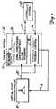
- Figure 2is an overview diagram of the hand controller, control system, and the controlled system.
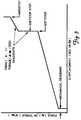
- Figure 3is a graph showing the relationship of hand grip-applied force/torque versus hand controller movement displacement profiles.
- Figure 4illustrates the vector relationships between base and platform coordinate frames of the virtual pivot hand controller.
- Figure 5a and 5bconstitute a signal flow diagram of the control system and motor channels.
- FIG. 1reveals an adaptable six degree of freedom virtual pivot hand controller 10.
- Virtual pivot hand controller 10has a hand grip 28 for the operator's input. Hand grip 28 is connected through grip platform 30 to six degree of freedom force and torque sensor 34. Force and torque sensor 34 is an F/T series, model 75/250 sensor from Assurance Technologies, Inc., of Garner, NC 27529.
- Grip platform 30is connected to shafts 62 via ball joints 32. Three shafts 62 extend into three linear actuators 36, respectively. Linear actuators 36 cause shafts 62 to extend out of actuators 36 or to withdraw into actuators 36. The amount of shaft 62 extending out of linear actuator 36 is measured by linear potentiometer 38. Linear actuators 36 are driven by motors 40 thereby causing the extension or withdrawal of shafts 62.
- the withdrawal or extension of shafts 62 via ball joints 32raise, lower, tilt, rotate and/or laterally move grip platform 30 and hand grip 28.
- the activity of motors 40 driving linear actuators 36is monitored by tachometers 42.
- Linear actuators 36are attached to universal joints 60, respectively.
- the other ends of the universal joints 60 opposite of linear actuators 36,are effectively attached to base plate 48.
- Six potentiometers 44are, respectively, attached to universal joints 60 for measuring the angles of linear actuators 36 relative to base plate 48.
- the angle of linear actuatoris 36, relative to base plate 48, is driven and set by motors 52 via gear heads 50 and worm and worm wheel assemblies 46.
- Gear heads 50are attached to motors 52 through base plate 48 to worms 46.
- Worms 46drive worm wheels 46 which are attached to the portions of universal joints 60 that are rigidly attached to linear actuators 36, respectively. Worms 46 driving worm wheels 46 set linear actuators 36 and shafts 62 to particular angles of inclination. Motors 52 are monitored by tachometers 54. Base plate 48 is supported by a surface 58 with structural supports 56. Surface 58 represents the place or area upon which hand controller 10 is situated and mounted.
- Figure 2reveals an overall diagram of the adaptable six degree of freedom virtual pivot hand controller 10 system.
- Hand controller 10outputs sensor signals 20 from six degree of freedom force and torque sensor 34, linear potentiometers 38, angular potentiometers 44, motor tachometers 42 and motor tachometers 54.
- Sensor signals 20are input to control system 12 which is a processor and specifically a single board microcomputer, as available under the type no. 68020 from Motorola Inc., Schaumburg J11. (USA), having system control 14 and force feedback control 16.
- Force and torque sensor 34which is attached to hand grip platform and hand grip monitors the control inputs from the operator.
- Control system 12in response to sensor signals 20, sends feedback signals to motors 40 and 52 to drive hand controller 10 in accordance with the commanded configuration, having appropriate force and feel characteristics.
- the force and feel characteristicsare determined by force feedback control 16 and response to sensor signals 20 revealing force, torque, position and rate, and signals from controlled system 18 sensors indicating proximity, force, field dynamics, etc., in response to driving signals 22 to system actuators such as motors, propulsion, etc.
- Hand controller 10uses motor biasing to generate the force and feel of springs, damping and mechanical deadbands as illustrated in Figure 3.
- Figure 3is a graph of hand grip applied force and torque versus displacement profiles of hand grip 10.
- Control interface 22 required to determine hand control 10 orientation and translation in six degrees of freedomcontains nine potentiometer measurements (three per leg) that define three position vectors of grip platform 10, corresponding to three fixed ball joints 32, with respect to the three base leg pivot points at the ends of shafts 62.
- a fixed displacement vector(from the origin of platform 30 coordinate frame) of the operator's wrist joint is estimated.
- Figure 4shows the vector relationships between base 48 and platform 30 coordinate frames.
- Processor or control system 12through force feedback control 16, returns three Euler angles and three linear translations from nominal platform 30 origin. Additionally, force and torque sensor 34 inputs are used in either position or rate mode to command a six degree of freedom velocity that motorized legs 36 and shaft drives 46 are to deliver.
- processor or control system 12must first solve the geometric task of computing orientation and translation, and then compute the requisite leg or shaft rotational and linear velocities that result in the commanded and controller state.
- Processor of control system 12is also a single board microcomputer as available under said type 68020 housed in a standard Motorola chassis having several analog-to-digital interface cards.
- Six tachometers 42 and 54 on three legs 62measure motor speeds of leg-extending or retracting motors 40 and leg-angular rotating motors 52. There are two motors, 40 and 52, per leg 62.
- Linear potentiometers 38measure leg 62 extension and two angular potentiometers 44 per leg 62 measure angles of each leg 62 relative to base 48. There is a total of nine potentiometers 38 and 44.
- Rate and position control modes of hand controller 10differ. In the position mode, removal of grip, force and torque commands from the operator causes hand controller 10 to remain at its latest attained attitude and linear displacement. Removal of input in the rate mode will cause a return of hand controller 10 to the initial displacement origin. Any of the six degrees of freedom of hand controller 10 may be locked out as desired. Software stops are provided to prevent hand controller 10 from running into hard stops which might cause damage.
- Figures 5a and 5bconstitute an overview signal flow diagram of hand controller 10 input and motor control channels.
- Force/torque sensor 34is a strain gauge type of sensor for detecting applied force and torque to hand grip 28 of controller 10.
- Interface 13provides for keyboard or other type of input to the processor which includes input command processing 68 and motor command 70.
- Interface 13is a RS-232 terminal interface for operator inputs of the controller 10 processor.
- Control system 66provides for needed interaction among force and torque sensor 34, input command processing 68 and interface 13.
- Control system 66includes sensor 34 electronics and control and may incorporate a Lord® preprocessor and a Lord® controller for sensor 34, from Assurance Technologies, Inc., of Garner, NC 27529.
- Controller function 72incorporates software to perform the calculations of required motor rates to equal commanded input velocities of translation and rotation by incorporation kinematic system equations.
- Orientation function 74incorporates software to perform the calculations of the platform and/or virtual pivot translation and rotation with respect to the base coordinate system. Inputs represent shaft or leg lengths, elevations and azimuth angles obtained from the nine potentiometers 38 and 44 (three per shaft or leg). Function 74 incorporates reverse kinematic system equations in its calculations.
- External object or device 18receives input for external control and outputs signals for providing reflected force or torque (i.e., "feel" dynamics), or alarms.
- the above dotrepresents a matrix dot product.
- the platform 30 X ⁇ P unit vectoris directed from the center toward P i .
- the ⁇ P unit vectoris parallel to the line from P3 to P2. Then,
- the direction cosines of the X ⁇ P , ⁇ P , and ⁇ P unit vectorsare the components of the preceding vector equations.
- the Euler rotation matrix from S B to S Pis then The above dots represent vector dot products.
- Euler anglescan be defined in 24 different ways depending on the sequence of rotations (in a positive sense about each of three axes). There are 12 permutations starting with either frame S P or S B , or 24 total. Each set of three angles is not interchangeable (except for very small rotations). Each set does, however, result in the same rotation of one frame to another when applied in its specific sequence.
- Tachometers 42 and 54 mounted on the handcontroller 10 legs and roll axis shaftsare used in a velocity feedback controller 16 that drives each motorized leg 62 to null a separate commanded velocity. These six velocities are in turn computed according to the six signals from force/torque sensor 34 (after biasing to provide reflected force or torque dynamics for the operator).
- handgrip 28 force signalsare interpreted as referenced to the base 48 coordinate frame as a linear velocity command.
- the coordinate system usedis arbitrary and can be easily redefined in processor code and provided as an optional handcontroller 10 operating mode at a later time if desired.
- the inertial velocity V ⁇ i of each leg 62is composed of the linear velocity of the platform 30 center summed with the rotational velocity about the center, that is where ⁇ i , ⁇ i , and d i are the time rate of change of angles ⁇ i ⁇ i , and leg length d i for each leg. Then,
- the platform 30 angular velocity vector input commands, ⁇ p, aboveare referenced to S B ; if they are instead referenced to S P , they are simply converted by the inverse Euler transformation as follows:
- the inverse Euler matrixis the transpose of the matrix since the coordinate frame is orthogonal and Cartesian.
- one feature of hand controller 10is that the sensed location of the pivot point can be set arbitrarily. It can be set through the center of grip 28, above or below it, or be centered inside the operator's wrist. For example, with a pivot point below grip 28, it would act like a conventional military aircraft hand controller having the pivot point where the control stick attaches to the floor or deck of the aircraft. However, with the pivot point above grip 28, the top of the grip would be seemingly attached to a point above it and the grip would swing freely below it. The programmability of the pivot point provides for maximum flexibility and adaptability of hand controller 10. These changes in location of pivot point can be made by entering the appropriate software commands in control system 12.
- An initial settingcan be made by the operator through the movement of his or her wrist for setting the virtual pivot and control swing and rotation dimensions in accordance with and to match the wrist movement.
- Other operating characteristicscan be changed simply by altering the software. Such things as break out forces, the degree of freedom available, damping rates, spring tensions and velocity rates can be modified without altering the hardware of control system 12 or hand controller 10.
- the operatoris given feedback through grip 28. This capability is force reflection and usually involves providing tactile feedback through grip 20 when the control object 18 (e.g., a robot arm or vehicle) contacts the target or other object.
- the combination of a programmable virtual pivot point having an active hand controller 10allows the operator or user to configure hand controller 10 to match or meet the demands or needs of a particular task and user.
- Motor-driven force feedbackreplaces spring centering. Gradients of forces or torques versus displacements (in each of six axes), as shown in Figure 2, are stored as parameters that can be modified by keyboard 13 input. Such modification provides adaptability or programmability of key hand controller 10 operating characteristics including sensed (virtual) pivot axes locations and range of motion in each axis, sensed spring force reflection or the feel of grip 28 (i.e., force/displacement gradients), the capability, as desired, to implement bilateral force feedback from system 18 being controlled (via motor control feedback) to the human operator and the capability of operator-mode control to introduce menu-driven commands (via the VMEbus single-board computer).
Landscapes
- Engineering & Computer Science (AREA)
- Physics & Mathematics (AREA)
- General Physics & Mathematics (AREA)
- Automation & Control Theory (AREA)
- General Engineering & Computer Science (AREA)
- Theoretical Computer Science (AREA)
- Human Computer Interaction (AREA)
- Robotics (AREA)
- Mechanical Engineering (AREA)
- Manipulator (AREA)
- Mechanical Control Devices (AREA)
- Control Of Position Or Direction (AREA)
Description
- The present invention pertains to hand controllers according to the preamble of
claim 1 and particularly to aircraft hand controllers. More particularly, the invention pertains to displacement aircraft or space vehicle hand controllers. - The related art involves conventional hand controllers which rotate about a fixed axis in the base, require movement of both the arm and the wrist, have a high force displacement gradient, and have either no or complex proprioceptive feedback.
- In recent years, space and weight constraints in modern aircraft have resulted in compact fly-by-wire or fly-by-light control systems. Such systems reduce the size and weight of flight control hardware in the cockpit. In addition, these systems permit a side-arm controller configuration that reduces obstruction of the instrument panel area directly in front of the pilot. Two general configurations of those compact controllers have been developed--rigid and movable displacement. Rigid controllers measure the force of the control input and have no movement associated with input magnitude. Moveable controllers have a range of motion of about ± 5 cm (± 2 inches) to ± 10 cm (± 4 inches) associated with the magnitude of the control input. The force required to fully displace a moveable controller may be quite small, although the inclusion of a force-displacement gradient has been found to improve control performance.
- Difficulties are associated with both types of hand controllers. Rigid controllers may produce severe operator fatigue due to a lack of proprioceptive feedback to tell the pilot how much force he is exerting. That difficulty can be reduced by allowing for a small (i.e., ± 6 mm or ± 1/4 inch) amount of displacement or wobble unrelated to the force-output function. Further, rigid controllers provide fairly imprecise control and suffer from input axis cross-coupling, again due to the poor proprioceptive feedback provided to the operator.
- Moveable controllers can provide reasonable control when a fairly heavy-force output gradient (i.e., ≧ 6,8 kg or > ± 15 pounds at full displacement) is used; however, these force requirements result in operator fatigue. At lower force requirements, control imprecision and axis cross-coupling are resulting problems.
- Some of these problems were solved upon the conception and development of a moveable hand controller configuration that permits accurate control while requiring a relatively low force-displacement gradient. Also, such hand controller is useful in a side-arm configuration in that it allows the operator's arm to remain essentially motionless in an arm rest while control inputs are made about the fulcrum of the wrist. When the operator provides an input, such hand controller assembly is rotated in an arc having its center at the operator's wrist and/or center is translational. The hand controller also has the advantage of rotation about the operator's wrist joint, thus requiring movement of the wrist only. In other words, that hand controller has a "virtual pivot" that permits inputs to be made about any point in space and the controller translates movement of the controller grip about a point in space (such as the operator's wrist joint) into movements of a sensor about an internal reference point thereby permitting one hand controller to optimally function for all hand sizes. However, that controller has a grip and a sensor platform with a small-displacement and a motion base with spring-loaded legs for flexibility. Such hand controller is disclosed in EP-A1-0 363 739.
- Departing from this known hand controller, it is the object of the present invention to further improve it so that it can be matched to different applications. This object is achieved according to the characterizing features of
claim 1. Further advantageous embodiments of the improved hand controller may be taken from the dependent claims. - The present invention is still yet a further improvement on the related art. Not only does the present invention have a virtual pivot which accommodates variations in operator action, have six degrees of freedom, and variable pivot point locations; the invention is adaptable for providing various forces and torques and displacements and rotations and provides force feedback which simulates spring-type feedback but having different rates, various stop positions, variable damping, and a variety of reflective conditions to the controller environment including impact, proximity, limits, etc. The system of the invention has a hand controller incorporating system actuators, system sensors and feedback actuators which are connected to system control and force feedback control mechanisms which implement a variable control algorithm. The controller has a hand grip platform which is supported by telescoping legs. Linear actuators drive the telescoping motion in the legs. Motors drive radial angular motion at the universal joints which attach the legs to the base plate. A force/torque sensor is attached to the hand grip platform and monitors control inputs from an operator of the hand controller. There are angular potentiometers, linear potentiometers, and motor tachometers associated with the telescoping legs. The potentiometers provide a measurement of the position and attitude of the platform with respect to the base. Signals from the force/torque sensor, angular potentiometers, linear potentiometers and motor tachometers are input into the control system. The control system sends signals to the motors to drive the hand controller to the commanded configuration with the appropriate force and feel characteristics at the hand grip.
- The virtual pivot of the hand controller system accommodates a wide variety of operator sizes with a "floating" pivot point. Motors and controllers replace springs of the related art hand controller and yet provides force feedback or "feel". Spring rates, spring tension, damping rates, stop positions, the number of control axes, the dimensions and range of control axes, and force reflection characteristics may be programmed with various values based on specific requirements into the control system. The programmability and flexibility of the hand controller system permits the controlling of a large and varied range of devices with a single hand controller. The hand controller system may be programmed to compensate for various gravities, various gravity and inertial effects, or for gravity-free environments. Applications of the hand controller system include use in space stations, space vehicles, helicopters, fixed-wing aircraft, underwater vehicles, robotic vehicles, robotic arm controls, and other applications.
- Figure 1 is a drawing of hand controller.
- Figure 2 is an overview diagram of the hand controller, control system, and the controlled system.
- Figure 3 is a graph showing the relationship of hand grip-applied force/torque versus hand controller movement displacement profiles.
- Figure 4 illustrates the vector relationships between base and platform coordinate frames of the virtual pivot hand controller.
- Figure 5a and 5b constitute a signal flow diagram of the control system and motor channels.
- Figure 1 reveals an adaptable six degree of freedom virtual
pivot hand controller 10. Virtualpivot hand controller 10 has ahand grip 28 for the operator's input.Hand grip 28 is connected throughgrip platform 30 to six degree of freedom force andtorque sensor 34. Force andtorque sensor 34 is an F/T series, model 75/250 sensor from Assurance Technologies, Inc., of Garner, NC 27529.Grip platform 30 is connected toshafts 62 viaball joints 32. Threeshafts 62 extend into threelinear actuators 36, respectively.Linear actuators 36 causeshafts 62 to extend out ofactuators 36 or to withdraw intoactuators 36. The amount ofshaft 62 extending out oflinear actuator 36 is measured bylinear potentiometer 38.Linear actuators 36 are driven bymotors 40 thereby causing the extension or withdrawal ofshafts 62. The withdrawal or extension ofshafts 62 viaball joints 32 raise, lower, tilt, rotate and/or laterally movegrip platform 30 andhand grip 28. The activity ofmotors 40 drivinglinear actuators 36 is monitored bytachometers 42.Linear actuators 36 are attached touniversal joints 60, respectively. The other ends of theuniversal joints 60 opposite oflinear actuators 36, are effectively attached tobase plate 48. Sixpotentiometers 44 are, respectively, attached touniversal joints 60 for measuring the angles oflinear actuators 36 relative tobase plate 48. The angle of linear actuator is 36, relative tobase plate 48, is driven and set bymotors 52 via gear heads 50 and worm andworm wheel assemblies 46. Gear heads 50 are attached tomotors 52 throughbase plate 48 toworms 46.Worms 46drive worm wheels 46 which are attached to the portions ofuniversal joints 60 that are rigidly attached tolinear actuators 36, respectively.Worms 46 drivingworm wheels 46 setlinear actuators 36 andshafts 62 to particular angles of inclination.Motors 52 are monitored bytachometers 54.Base plate 48 is supported by asurface 58 withstructural supports 56.Surface 58 represents the place or area upon whichhand controller 10 is situated and mounted. - Figure 2 reveals an overall diagram of the adaptable six degree of freedom virtual
pivot hand controller 10 system.Hand controller 10 outputs sensor signals 20 from six degree of freedom force andtorque sensor 34,linear potentiometers 38,angular potentiometers 44,motor tachometers 42 andmotor tachometers 54. Sensor signals 20 are input to controlsystem 12 which is a processor and specifically a single board microcomputer, as available under the type no. 68020 from Motorola Inc., Schaumburg J11. (USA), havingsystem control 14 and force feedback control 16. Force andtorque sensor 34 which is attached to hand grip platform and hand grip monitors the control inputs from the operator.Control system 12, in response to sensor signals 20, sends feedback signals tomotors hand controller 10 in accordance with the commanded configuration, having appropriate force and feel characteristics. The force and feel characteristics are determined by force feedback control 16 and response to sensor signals 20 revealing force, torque, position and rate, and signals from controlledsystem 18 sensors indicating proximity, force, field dynamics, etc., in response to drivingsignals 22 to system actuators such as motors, propulsion, etc.Hand controller 10 uses motor biasing to generate the force and feel of springs, damping and mechanical deadbands as illustrated in Figure 3. Figure 3 is a graph of hand grip applied force and torque versus displacement profiles ofhand grip 10. Control interface 22 required to determinehand control 10 orientation and translation in six degrees of freedom contains nine potentiometer measurements (three per leg) that define three position vectors ofgrip platform 10, corresponding to three fixed ball joints 32, with respect to the three base leg pivot points at the ends ofshafts 62. During system calibration, a fixed displacement vector (from the origin ofplatform 30 coordinate frame) of the operator's wrist joint is estimated. Figure 4 shows the vector relationships betweenbase 48 andplatform 30 coordinate frames. Processor orcontrol system 12, through force feedback control 16, returns three Euler angles and three linear translations fromnominal platform 30 origin. Additionally, force andtorque sensor 34 inputs are used in either position or rate mode to command a six degree of freedom velocity thatmotorized legs 36 and shaft drives 46 are to deliver. Thus, processor orcontrol system 12 must first solve the geometric task of computing orientation and translation, and then compute the requisite leg or shaft rotational and linear velocities that result in the commanded and controller state.- Kinematic solutions to the hand grip platform Euler angles (defining attitude angles) and linear displacements from the center of the coordinate frame are obtained by use of nine potentiometers, 38 and 44. Fewer potentiometers can accomplish the same task of monitoring as the nine potentiometers. Telescoping legs or shafts 62 (whose links are actuator 36 driven) are attached to
platform 30 byball joints 32 and to base 48 by double-gimbaled motorized joints 60.Outer gimbals 60 are rigidly attached tobase 48, aremotor 52 driven, and cause a roll motion about the leg orshaft 62 motor axis of rotation.Outer gimbal 62 axis defines the leg orshaft 62 coordinate frame X-axis for each of the three legs orshafts 62. These three axes are each oriented along the radial directions with respect to the center ofbase 48. This results in theforward base 48 point having its motor axes along the X-axis of the base 48 coordinate frame. Azimuth angles φi to the other two base 48 points have constant values of 120 and 240 degrees, respectively.Inner gimbals 60 allow rotation about the respective leg orshaft 62 pitch axes. Designating the length of the three legs 62 di, where i equals 1, 2, 3, and is defined 0 < dimin < di < dimax. Then the position vectors ofplatform 30ball joints 32 with respect tobase 48 frame SB:


- Processor of
control system 12 is also a single board microcomputer as available under said type 68020 housed in a standard Motorola chassis having several analog-to-digital interface cards. Sixtachometers legs 62 measure motor speeds of leg-extending or retractingmotors 40 and leg-angularrotating motors 52. There are two motors, 40 and 52, perleg 62.Linear potentiometers 38measure leg 62 extension and twoangular potentiometers 44 perleg 62 measure angles of eachleg 62 relative tobase 48. There is a total of ninepotentiometers - Rate and position control modes of
hand controller 10 differ. In the position mode, removal of grip, force and torque commands from the operator causeshand controller 10 to remain at its latest attained attitude and linear displacement. Removal of input in the rate mode will cause a return ofhand controller 10 to the initial displacement origin. Any of the six degrees of freedom ofhand controller 10 may be locked out as desired. Software stops are provided to preventhand controller 10 from running into hard stops which might cause damage. - Figures 5a and 5b constitute an overview signal flow diagram of
hand controller 10 input and motor control channels. Force/torque sensor 34 is a strain gauge type of sensor for detecting applied force and torque to handgrip 28 ofcontroller 10.Interface 13 provides for keyboard or other type of input to the processor which includesinput command processing 68 andmotor command 70.Interface 13 is a RS-232 terminal interface for operator inputs of thecontroller 10 processor.Control system 66 provides for needed interaction among force andtorque sensor 34,input command processing 68 andinterface 13.Control system 66 includessensor 34 electronics and control and may incorporate a Lord® preprocessor and a Lord® controller forsensor 34, from Assurance Technologies, Inc., of Garner, NC 27529.Controller function 72 incorporates software to perform the calculations of required motor rates to equal commanded input velocities of translation and rotation by incorporation kinematic system equations.Orientation function 74 incorporates software to perform the calculations of the platform and/or virtual pivot translation and rotation with respect to the base coordinate system. Inputs represent shaft or leg lengths, elevations and azimuth angles obtained from the ninepotentiometers 38 and 44 (three per shaft or leg).Function 74 incorporates reverse kinematic system equations in its calculations. External object ordevice 18 receives input for external control and outputs signals for providing reflected force or torque (i.e., "feel" dynamics), or alarms. - The following describes the geometric relationships. Position vectors of the pivots are defined by


platform 30 frame), results in


or
- The above dot represents a matrix dot product. Referring to Figure 4, the
platform 30 X̂P unit vector is directed from the center toward Pi. The ŶP unit vector is parallel to the line from P₃ to P₂. Then,


- The direction cosines of the X̂P, ŶP, and ẐP unit vectors are the components of the preceding vector equations. The Euler rotation matrix from SB to SP is then

- All information concerning the relative attitude orientation between the base 48 and
platform 30 frames is contained in the Euler matrix EP/B. Euler angles can be defined in 24 different ways depending on the sequence of rotations (in a positive sense about each of three axes). There are 12 permutations starting with either frame SP or SB, or 24 total. Each set of three angles is not interchangeable (except for very small rotations). Each set does, however, result in the same rotation of one frame to another when applied in its specific sequence. - The following set arises from a yaw rotation about the SB z axis followed by a pitch rotation bout the y axis and a final roll about the x axis:


- Each rotation assumes the right-hand rule for positive sense. The inverse transformation performs a roll-pitch-yaw transformation (in that order) which is not uncommon in the aircraft industry.
- The following describes the platform velocity equations.
Tachometers handcontroller 10 legs and roll axis shafts are used in a velocity feedback controller 16 that drives eachmotorized leg 62 to null a separate commanded velocity. These six velocities are in turn computed according to the six signals from force/torque sensor 34 (after biasing to provide reflected force or torque dynamics for the operator). - At present,
handgrip 28 force signals are interpreted as referenced to the base 48 coordinate frame as a linear velocity command. The coordinate system used is arbitrary and can be easily redefined in processor code and provided as anoptional handcontroller 10 operating mode at a later time if desired. - The inertial velocity

leg 62 is composed of the linear velocity of theplatform 30 center summed with the rotational velocity about the center, that is


- In the above equation, only the expressions for leg roll and length rates are of interest as the
handcontroller 10leg 62 pitching rates are automatically driven by mechanical constraints. This solution requires inversion of a 3 by 3 matrix, where
- The
platform 30 angular velocity vector input commands, ωp, above are referenced to SB; if they are instead referenced to SP, they are simply converted by the inverse Euler transformation as follows:
- The inverse Euler matrix is the transpose of the matrix since the coordinate frame is orthogonal and Cartesian.
- In summary, one feature of
hand controller 10 is that the sensed location of the pivot point can be set arbitrarily. It can be set through the center ofgrip 28, above or below it, or be centered inside the operator's wrist. For example, with a pivot point belowgrip 28, it would act like a conventional military aircraft hand controller having the pivot point where the control stick attaches to the floor or deck of the aircraft. However, with the pivot point abovegrip 28, the top of the grip would be seemingly attached to a point above it and the grip would swing freely below it. The programmability of the pivot point provides for maximum flexibility and adaptability ofhand controller 10. These changes in location of pivot point can be made by entering the appropriate software commands incontrol system 12. An initial setting can be made by the operator through the movement of his or her wrist for setting the virtual pivot and control swing and rotation dimensions in accordance with and to match the wrist movement. Other operating characteristics can be changed simply by altering the software. Such things as break out forces, the degree of freedom available, damping rates, spring tensions and velocity rates can be modified without altering the hardware ofcontrol system 12 orhand controller 10. Based on information from the vehicle or object being controlled, the operator is given feedback throughgrip 28. This capability is force reflection and usually involves providing tactile feedback throughgrip 20 when the control object 18 (e.g., a robot arm or vehicle) contacts the target or other object. The combination of a programmable virtual pivot point having anactive hand controller 10 allows the operator or user to configurehand controller 10 to match or meet the demands or needs of a particular task and user. - Motor-driven force feedback (
microprocessor 12 control) replaces spring centering. Gradients of forces or torques versus displacements (in each of six axes), as shown in Figure 2, are stored as parameters that can be modified bykeyboard 13 input. Such modification provides adaptability or programmability ofkey hand controller 10 operating characteristics including sensed (virtual) pivot axes locations and range of motion in each axis, sensed spring force reflection or the feel of grip 28 (i.e., force/displacement gradients), the capability, as desired, to implement bilateral force feedback fromsystem 18 being controlled (via motor control feedback) to the human operator and the capability of operator-mode control to introduce menu-driven commands (via the VMEbus single-board computer).


Claims (7)
- A six degree-of-freedom virtual pivot hand controller (10) comprising:- grip means (28) for receiving externally applied force and torque;- force and torque sensing means (34) connected to said grip means for sensing the force and torque from up to six degrees-of-freedom applied to said grip means;- first support means (30) connected to said sensing means for supporting said sensing means;- second support means (48) for supporting said hand controller (10);- at least one variable-length member means (62) having a first flexible connector (32) attached to said first support means (30) and a second flexible connector (60) attached to said second support means (48) for variable supporting said first support means, wherein- said at least one variable-length member means (62) comprises:-- translation actuating means (36, 40) connected to said member means (62) for varying the length of said member means,-- translational sensing means (38) connected to said member means (62) for sensing a length of said member means,-- angular actuating means (46, 50, 52) connected to said member means (62) for angularly moving said member means (62) relative to said second support means, and-- angular sensing means (44) connected to said member means (62) for sensing an angular position of said member means (62) relative to said second support means.
- Controller according to claim 1,characterized by comprising processing and control means (12) connected to said force and torque sensing means (34), to said translational sensing means (38), to said angular sensing means (44), to said translational actuating means (36, 40) and to said angular actuating means (46, 50, 52), for receiving signals from said force and torque sensing means, said translational sensing means and said angular sensing means, and for sending signals to said translational actuating means and to said angular actuating means.
- Controller according to claim 2,characterized in that said processing and control means (12) sends signals to an external device (18) to be controlled by said hand controller (10), and receives signals for the external device.
- Controller according to claim 3,characterized in that a spring-like reflective force and torque is produced whereby any externally applied force and torque to said grip means (28) is sensed by said force and torque sensing means (34) which in turn sends signals indicating force and torque to said processing and control means (12) which in turn sends signals indicating certain kinds of control to the external device (18) being controlled which in turn sends signals of action and reflective force of the external device to said processing and control means which in turn sends signals of reflective force and movement to said translational actuating means and to said angular actuating means which in turn provide reflective force, torque and movement in response to the any externally applied force and torque to said grip means.
- Controller according to claim 4,characterized in that said grip means (28) reflects a virtual pivot point due to the spring-like reflective force and torque, and a movement due to the any externally applied force and torque.
- Controller according to claim 4,characterized in thata location of the virtual pivot point and magnitudes of the spring-like reflective force and torque and of movement may be varied via input information to said processing and control means (12).
- Controller according to claim 1,characterized in that- said first flexible connector is a ball joint (32);- said second flexible connector is a universal joint (60);- said translation actuating means comprises a first motor (40) connected to said interface and control means (12) for drawing said actuating means which changes length of said variable-length member means (62);- said translational sensing means comprises: a first tachometer (42) connected to the first motor and to said interface and control means, and a linear potentiometer (38) connected to said linear actuator and to said interface and control means;- said angular actuating means further comprises a second motor (52) connected to said interface and control means for driving said angular actuating means; and- said angular sensing means comprises:-- a first angular potentiometer (44) connected to said universal joint and to said interface and control means,-- a second angular potentiometer (44) connected to said universal joint and to said interface and control means, and-- a second tachometer (54) connected to the second motor (52) and to said interface and control means.
Applications Claiming Priority (2)
| Application Number | Priority Date | Filing Date | Title |
|---|---|---|---|
| US07/636,318US5223776A (en) | 1990-12-31 | 1990-12-31 | Six-degree virtual pivot controller |
| US636318 | 1990-12-31 |
Publications (2)
| Publication Number | Publication Date |
|---|---|
| EP0493795A1 EP0493795A1 (en) | 1992-07-08 |
| EP0493795B1true EP0493795B1 (en) | 1996-01-17 |
Family
ID=24551368
Family Applications (1)
| Application Number | Title | Priority Date | Filing Date |
|---|---|---|---|
| EP91122237AExpired - LifetimeEP0493795B1 (en) | 1990-12-31 | 1991-12-27 | Hand controller |
Country Status (4)
| Country | Link |
|---|---|
| US (1) | US5223776A (en) |
| EP (1) | EP0493795B1 (en) |
| JP (1) | JPH0573150A (en) |
| DE (1) | DE69116540T2 (en) |
Cited By (4)
| Publication number | Priority date | Publication date | Assignee | Title |
|---|---|---|---|---|
| US6405158B1 (en) | 1993-10-01 | 2002-06-11 | Massachusetts Institute Of Technology | Force reflecting haptic inteface |
| US6985133B1 (en) | 1998-07-17 | 2006-01-10 | Sensable Technologies, Inc. | Force reflecting haptic interface |
| US7411576B2 (en) | 2003-10-30 | 2008-08-12 | Sensable Technologies, Inc. | Force reflecting haptic interface |
| US11479364B2 (en) | 2017-12-13 | 2022-10-25 | Safe Flight Instrument, Llc | Aircraft torque control device |
Families Citing this family (173)
| Publication number | Priority date | Publication date | Assignee | Title |
|---|---|---|---|---|
| US5392384A (en)* | 1991-04-09 | 1995-02-21 | Kabushiki Kaisha Yaskawa Denki | Method of calibrating an industrial robot |
| US5889670A (en) | 1991-10-24 | 1999-03-30 | Immersion Corporation | Method and apparatus for tactilely responsive user interface |
| US5790108A (en) | 1992-10-23 | 1998-08-04 | University Of British Columbia | Controller |
| US7345672B2 (en)* | 1992-12-02 | 2008-03-18 | Immersion Corporation | Force feedback system and actuator power management |
| US6131097A (en)* | 1992-12-02 | 2000-10-10 | Immersion Corporation | Haptic authoring |
| US6801008B1 (en) | 1992-12-02 | 2004-10-05 | Immersion Corporation | Force feedback system and actuator power management |
| US5389865A (en)* | 1992-12-02 | 1995-02-14 | Cybernet Systems Corporation | Method and system for providing a tactile virtual reality and manipulator defining an interface device therefor |
| US6433771B1 (en) | 1992-12-02 | 2002-08-13 | Cybernet Haptic Systems Corporation | Haptic device attribute control |
| US5629594A (en)* | 1992-12-02 | 1997-05-13 | Cybernet Systems Corporation | Force feedback system |
| JPH06289988A (en)* | 1993-03-31 | 1994-10-18 | Suzuki Motor Corp | Three-dimensional input device |
| US5734373A (en) | 1993-07-16 | 1998-03-31 | Immersion Human Interface Corporation | Method and apparatus for controlling force feedback interface systems utilizing a host computer |
| US5739811A (en) | 1993-07-16 | 1998-04-14 | Immersion Human Interface Corporation | Method and apparatus for controlling human-computer interface systems providing force feedback |
| WO1995002801A1 (en) | 1993-07-16 | 1995-01-26 | Immersion Human Interface | Three-dimensional mechanical mouse |
| US5721566A (en) | 1995-01-18 | 1998-02-24 | Immersion Human Interface Corp. | Method and apparatus for providing damping force feedback |
| US5805140A (en)* | 1993-07-16 | 1998-09-08 | Immersion Corporation | High bandwidth force feedback interface using voice coils and flexures |
| US6437771B1 (en)* | 1995-01-18 | 2002-08-20 | Immersion Corporation | Force feedback device including flexure member between actuator and user object |
| US5731804A (en)* | 1995-01-18 | 1998-03-24 | Immersion Human Interface Corp. | Method and apparatus for providing high bandwidth, low noise mechanical I/O for computer systems |
| US6057828A (en)* | 1993-07-16 | 2000-05-02 | Immersion Corporation | Method and apparatus for providing force sensations in virtual environments in accordance with host software |
| US5414620A (en)* | 1993-08-09 | 1995-05-09 | Honeywell Inc. | Synthetic friction algorithm for a hand control element |
| WO1995004959A1 (en)* | 1993-08-10 | 1995-02-16 | Honeywell Inc. | Second generation six-degree-of-freedom virtual pivot hand controller |
| US6004134A (en)* | 1994-05-19 | 1999-12-21 | Exos, Inc. | Interactive simulation including force feedback |
| US5623582A (en) | 1994-07-14 | 1997-04-22 | Immersion Human Interface Corporation | Computer interface or control input device for laparoscopic surgical instrument and other elongated mechanical objects |
| US5821920A (en) | 1994-07-14 | 1998-10-13 | Immersion Human Interface Corporation | Control input device for interfacing an elongated flexible object with a computer system |
| US20030040361A1 (en)* | 1994-09-21 | 2003-02-27 | Craig Thorner | Method and apparatus for generating tactile feedback via relatively low-burden and/or zero burden telemetry |
| US5642469A (en) | 1994-11-03 | 1997-06-24 | University Of Washington | Direct-drive manipulator for pen-based force display |
| US5666138A (en) | 1994-11-22 | 1997-09-09 | Culver; Craig F. | Interface control |
| US6850222B1 (en) | 1995-01-18 | 2005-02-01 | Immersion Corporation | Passive force feedback for computer interface devices |
| US6400352B1 (en) | 1995-01-18 | 2002-06-04 | Immersion Corporation | Mechanical and force transmission for force feedback devices |
| US5847528A (en)* | 1995-05-19 | 1998-12-08 | Canadian Space Agency | Mechanism for control of position and orientation in three dimensions |
| US5691898A (en)* | 1995-09-27 | 1997-11-25 | Immersion Human Interface Corp. | Safe and low cost computer peripherals with force feedback for consumer applications |
| US7113166B1 (en) | 1995-06-09 | 2006-09-26 | Immersion Corporation | Force feedback devices using fluid braking |
| US6166723A (en)* | 1995-11-17 | 2000-12-26 | Immersion Corporation | Mouse interface device providing force feedback |
| US5999168A (en) | 1995-09-27 | 1999-12-07 | Immersion Corporation | Haptic accelerator for force feedback computer peripherals |
| US5959613A (en) | 1995-12-01 | 1999-09-28 | Immersion Corporation | Method and apparatus for shaping force signals for a force feedback device |
| US5754023A (en) | 1995-10-26 | 1998-05-19 | Cybernet Systems Corporation | Gyro-stabilized platforms for force-feedback applications |
| US6100874A (en)* | 1995-11-17 | 2000-08-08 | Immersion Corporation | Force feedback mouse interface |
| US5825308A (en)* | 1996-11-26 | 1998-10-20 | Immersion Human Interface Corporation | Force feedback interface having isotonic and isometric functionality |
| US6639581B1 (en) | 1995-11-17 | 2003-10-28 | Immersion Corporation | Flexure mechanism for interface device |
| US6704001B1 (en) | 1995-11-17 | 2004-03-09 | Immersion Corporation | Force feedback device including actuator with moving magnet |
| US6061004A (en)* | 1995-11-26 | 2000-05-09 | Immersion Corporation | Providing force feedback using an interface device including an indexing function |
| EP0864145A4 (en) | 1995-11-30 | 1998-12-16 | Virtual Technologies Inc | Tactile feedback man-machine interface device |
| US6219032B1 (en) | 1995-12-01 | 2001-04-17 | Immersion Corporation | Method for providing force feedback to a user of an interface device based on interactions of a controlled cursor with graphical elements in a graphical user interface |
| US8508469B1 (en) | 1995-12-01 | 2013-08-13 | Immersion Corporation | Networked applications including haptic feedback |
| US6028593A (en)* | 1995-12-01 | 2000-02-22 | Immersion Corporation | Method and apparatus for providing simulated physical interactions within computer generated environments |
| US6169540B1 (en) | 1995-12-01 | 2001-01-02 | Immersion Corporation | Method and apparatus for designing force sensations in force feedback applications |
| US6147674A (en) | 1995-12-01 | 2000-11-14 | Immersion Corporation | Method and apparatus for designing force sensations in force feedback computer applications |
| US7027032B2 (en) | 1995-12-01 | 2006-04-11 | Immersion Corporation | Designing force sensations for force feedback computer applications |
| US6078308A (en)* | 1995-12-13 | 2000-06-20 | Immersion Corporation | Graphical click surfaces for force feedback applications to provide user selection using cursor interaction with a trigger position within a boundary of a graphical object |
| US6300936B1 (en)* | 1997-11-14 | 2001-10-09 | Immersion Corporation | Force feedback system including multi-tasking graphical host environment and interface device |
| US6128970A (en)* | 1995-12-29 | 2000-10-10 | Daewoo Electroniccs Co., Ltd. | Force feed back manipulator employing wires and spools |
| KR0151349B1 (en)* | 1995-12-29 | 1998-10-15 | 배순훈 | Manipulator of simulator |
| SE519661C2 (en)* | 1996-02-23 | 2003-03-25 | Immersion Corp | Pointing devices and method for marking graphic details on a display with sensory feedback upon finding said detail |
| DE19608869C2 (en)* | 1996-03-07 | 1998-03-26 | Daimler Benz Ag | Operating system, in particular for components in a motor vehicle |
| US6050718A (en)* | 1996-03-28 | 2000-04-18 | Immersion Corporation | Method and apparatus for providing high bandwidth force feedback with improved actuator feel |
| US7225404B1 (en)* | 1996-04-04 | 2007-05-29 | Massachusetts Institute Of Technology | Method and apparatus for determining forces to be applied to a user through a haptic interface |
| US6111577A (en) | 1996-04-04 | 2000-08-29 | Massachusetts Institute Of Technology | Method and apparatus for determining forces to be applied to a user through a haptic interface |
| US6374255B1 (en)* | 1996-05-21 | 2002-04-16 | Immersion Corporation | Haptic authoring |
| JP3436639B2 (en)* | 1996-07-05 | 2003-08-11 | 日本輸送機株式会社 | Steering input device for omnidirectional vehicles |
| US6084587A (en) | 1996-08-02 | 2000-07-04 | Sensable Technologies, Inc. | Method and apparatus for generating and interfacing with a haptic virtual reality environment |
| US6024576A (en) | 1996-09-06 | 2000-02-15 | Immersion Corporation | Hemispherical, high bandwidth mechanical interface for computer systems |
| US5828197A (en)* | 1996-10-25 | 1998-10-27 | Immersion Human Interface Corporation | Mechanical interface having multiple grounded actuators |
| US6411276B1 (en) | 1996-11-13 | 2002-06-25 | Immersion Corporation | Hybrid control of haptic feedback for host computer and interface device |
| US6128006A (en)* | 1998-03-26 | 2000-10-03 | Immersion Corporation | Force feedback mouse wheel and other control wheels |
| US6956558B1 (en) | 1998-03-26 | 2005-10-18 | Immersion Corporation | Rotary force feedback wheels for remote control devices |
| US6154201A (en)* | 1996-11-26 | 2000-11-28 | Immersion Corporation | Control knob with multiple degrees of freedom and force feedback |
| US7489309B2 (en)* | 1996-11-26 | 2009-02-10 | Immersion Corporation | Control knob with multiple degrees of freedom and force feedback |
| US6686911B1 (en) | 1996-11-26 | 2004-02-03 | Immersion Corporation | Control knob with control modes and force feedback |
| US6636197B1 (en) | 1996-11-26 | 2003-10-21 | Immersion Corporation | Haptic feedback effects for control, knobs and other interface devices |
| WO1998033136A1 (en)* | 1997-01-27 | 1998-07-30 | Immersion Human Interface Corporation | Method and apparatus for providing high bandwidth, realistic force feedback including an improved actuator |
| DE19713245C2 (en)* | 1997-03-29 | 2001-02-15 | Mercedes Benz Lenkungen Gmbh | Motor vehicle with at least one part controllable via at least one control lever in the form of a so-called side stick |
| US6020876A (en)* | 1997-04-14 | 2000-02-01 | Immersion Corporation | Force feedback interface with selective disturbance filter |
| US6047610A (en)* | 1997-04-18 | 2000-04-11 | Stocco; Leo J | Hybrid serial/parallel manipulator |
| US6292170B1 (en) | 1997-04-25 | 2001-09-18 | Immersion Corporation | Designing compound force sensations for computer applications |
| US6285351B1 (en) | 1997-04-25 | 2001-09-04 | Immersion Corporation | Designing force sensations for computer applications including sounds |
| US6292174B1 (en) | 1997-08-23 | 2001-09-18 | Immersion Corporation | Enhanced cursor control using limited-workspace force feedback devices |
| US6252579B1 (en) | 1997-08-23 | 2001-06-26 | Immersion Corporation | Interface device and method for providing enhanced cursor control with force feedback |
| US6104382A (en) | 1997-10-31 | 2000-08-15 | Immersion Corporation | Force feedback transmission mechanisms |
| US6020875A (en)* | 1997-10-31 | 2000-02-01 | Immersion Corporation | High fidelity mechanical transmission system and interface device |
| US6281651B1 (en) | 1997-11-03 | 2001-08-28 | Immersion Corporation | Haptic pointing devices |
| US6088019A (en)* | 1998-06-23 | 2000-07-11 | Immersion Corporation | Low cost force feedback device with actuator for non-primary axis |
| US6252583B1 (en) | 1997-11-14 | 2001-06-26 | Immersion Corporation | Memory and force output management for a force feedback system |
| US6211861B1 (en)* | 1998-06-23 | 2001-04-03 | Immersion Corporation | Tactile mouse device |
| US6243078B1 (en) | 1998-06-23 | 2001-06-05 | Immersion Corporation | Pointing device with forced feedback button |
| US6256011B1 (en) | 1997-12-03 | 2001-07-03 | Immersion Corporation | Multi-function control device with force feedback |
| US6191796B1 (en) | 1998-01-21 | 2001-02-20 | Sensable Technologies, Inc. | Method and apparatus for generating and interfacing with rigid and deformable surfaces in a haptic virtual reality environment |
| US6437770B1 (en) | 1998-01-26 | 2002-08-20 | University Of Washington | Flat-coil actuator having coil embedded in linkage |
| US20080055241A1 (en)* | 1998-03-26 | 2008-03-06 | Immersion Corporation | Systems and Methods for Haptic Feedback Effects for Control Knobs |
| US6067077A (en)* | 1998-04-10 | 2000-05-23 | Immersion Corporation | Position sensing for force feedback devices |
| US6429846B2 (en) | 1998-06-23 | 2002-08-06 | Immersion Corporation | Haptic feedback for touchpads and other touch controls |
| US6707443B2 (en) | 1998-06-23 | 2004-03-16 | Immersion Corporation | Haptic trackball device |
| US6184868B1 (en) | 1998-09-17 | 2001-02-06 | Immersion Corp. | Haptic feedback control devices |
| US6697043B1 (en) | 1999-12-21 | 2004-02-24 | Immersion Corporation | Haptic interface device and actuator assembly providing linear haptic sensations |
| US6717573B1 (en) | 1998-06-23 | 2004-04-06 | Immersion Corporation | Low-cost haptic mouse implementations |
| US6552722B1 (en) | 1998-07-17 | 2003-04-22 | Sensable Technologies, Inc. | Systems and methods for sculpting virtual objects in a haptic virtual reality environment |
| US6421048B1 (en) | 1998-07-17 | 2002-07-16 | Sensable Technologies, Inc. | Systems and methods for interacting with virtual objects in a haptic virtual reality environment |
| US7038667B1 (en)* | 1998-10-26 | 2006-05-02 | Immersion Corporation | Mechanisms for control knobs and other interface devices |
| DE19856722A1 (en)* | 1998-12-09 | 2000-06-15 | Mannesmann Vdo Ag | Operating device with a handle with at least two degrees of freedom of adjustment |
| US6781569B1 (en) | 1999-06-11 | 2004-08-24 | Immersion Corporation | Hand controller |
| US6424356B2 (en) | 1999-05-05 | 2002-07-23 | Immersion Corporation | Command of force sensations in a forceback system using force effect suites |
| US6762745B1 (en) | 1999-05-10 | 2004-07-13 | Immersion Corporation | Actuator control providing linear and continuous force output |
| DE20080209U1 (en) | 1999-09-28 | 2001-08-09 | Immersion Corp | Control of haptic sensations for interface devices with vibrotactile feedback |
| US6822635B2 (en) | 2000-01-19 | 2004-11-23 | Immersion Corporation | Haptic interface for laptop computers and other portable devices |
| JP2002062944A (en)* | 2000-08-18 | 2002-02-28 | Alps Electric Co Ltd | On-vehicle input device |
| US7084854B1 (en) | 2000-09-28 | 2006-08-01 | Immersion Corporation | Actuator for providing tactile sensations and device for directional tactile sensations |
| EP1199622B1 (en)* | 2000-10-20 | 2007-12-12 | Deere & Company | Operating element |
| US6867770B2 (en) | 2000-12-14 | 2005-03-15 | Sensable Technologies, Inc. | Systems and methods for voxel warping |
| US6958752B2 (en) | 2001-01-08 | 2005-10-25 | Sensable Technologies, Inc. | Systems and methods for three-dimensional modeling |
| US6459228B1 (en) | 2001-03-22 | 2002-10-01 | Mpc Products Corporation | Dual input servo coupled control sticks |
| IL143255A (en) | 2001-05-20 | 2015-09-24 | Simbionix Ltd | Endoscopic ultrasonography simulation |
| ATE418096T1 (en) | 2001-10-29 | 2009-01-15 | Albert Schaeffer | INPUT DEVICE USING THE PARALLEL KINEMATIC PRINCIPLE AND WITH HAPTIC FEEDBACK |
| US6904823B2 (en) | 2002-04-03 | 2005-06-14 | Immersion Corporation | Haptic shifting devices |
| US6671651B2 (en)* | 2002-04-26 | 2003-12-30 | Sensable Technologies, Inc. | 3-D selection and manipulation with a multiple dimension haptic interface |
| AU2003257309A1 (en) | 2002-08-13 | 2004-02-25 | Microbotics Corporation | Microsurgical robot system |
| US8830161B2 (en) | 2002-12-08 | 2014-09-09 | Immersion Corporation | Methods and systems for providing a virtual touch haptic effect to handheld communication devices |
| AU2003298038A1 (en) | 2002-12-08 | 2004-06-30 | Immersion Corporation | Using haptic effects to enhance information content in communications |
| US8059088B2 (en) | 2002-12-08 | 2011-11-15 | Immersion Corporation | Methods and systems for providing haptic messaging to handheld communication devices |
| FR2849937B1 (en)* | 2003-01-13 | 2005-02-11 | Commissariat Energie Atomique | MANUAL SIMULATION INTERFACE |
| DE10310717A1 (en)* | 2003-03-10 | 2004-09-23 | Wittenstein Ag | Helicopter or simulator control device, has a control assembly that has a linear movement mechanism that is activated using a handgrip to control rotational movement of a drive element |
| US7850456B2 (en) | 2003-07-15 | 2010-12-14 | Simbionix Ltd. | Surgical simulation device, system and method |
| USD510739S1 (en) | 2003-10-30 | 2005-10-18 | Sensable Technologies, Inc. | Computer interface |
| US7889209B2 (en)* | 2003-12-10 | 2011-02-15 | Sensable Technologies, Inc. | Apparatus and methods for wrapping texture onto the surface of a virtual object |
| US7626589B2 (en)* | 2003-12-10 | 2009-12-01 | Sensable Technologies, Inc. | Haptic graphical user interface for adjusting mapped texture |
| US7149596B2 (en)* | 2004-01-13 | 2006-12-12 | Sensable Technologies, Inc. | Apparatus and methods for modifying a model of an object to enforce compliance with a manufacturing constraint |
| DE102004004678B4 (en)* | 2004-01-29 | 2005-12-29 | Otto Bock Healthcare Gmbh | torque sensor |
| JP2005332039A (en)* | 2004-05-18 | 2005-12-02 | Alps Electric Co Ltd | Force sense giving type input device |
| US7456821B2 (en)* | 2004-11-30 | 2008-11-25 | Immersion Corporation | User interface device |
| CA2646390C (en)* | 2006-02-17 | 2014-09-23 | Oceaneering International, Inc. | A multi-mode manipulator arm and drive system |
| EP2126646B1 (en) | 2006-12-27 | 2012-08-22 | Mako Surgical Corp. | Apparatus and method for providing an adjustable positive stop in space |
| WO2008087629A2 (en) | 2007-01-16 | 2008-07-24 | Simbionix Ltd. | Preoperative surgical simulation |
| US8543338B2 (en) | 2007-01-16 | 2013-09-24 | Simbionix Ltd. | System and method for performing computerized simulations for image-guided procedures using a patient specific model |
| US20100001878A1 (en)* | 2008-02-21 | 2010-01-07 | Honeywell International Inc. | Apparatus for controlling an object that is movable within a coordinate system having a plurality of axes |
| US8056432B2 (en) | 2008-09-19 | 2011-11-15 | Honeywell International Inc. | Active control stick assembly |
| US8052185B2 (en)* | 2009-04-09 | 2011-11-08 | Disney Enterprises, Inc. | Robot hand with humanoid fingers |
| US8327715B2 (en)* | 2009-07-02 | 2012-12-11 | Honeywell International Inc. | Force sensor apparatus |
| US8542105B2 (en) | 2009-11-24 | 2013-09-24 | Immersion Corporation | Handheld computer interface with haptic feedback |
| SG177791A1 (en)* | 2010-07-20 | 2012-02-28 | Isela Pte Ltd | A controller |
| USD678848S1 (en)* | 2010-09-01 | 2013-03-26 | Lectronix, Inc. | Center console single hand controller |
| US8316725B2 (en) | 2010-12-15 | 2012-11-27 | Honeywell International Inc. | Force sensor |
| US9802364B2 (en) | 2011-10-18 | 2017-10-31 | 3D Systems, Inc. | Systems and methods for construction of an instruction set for three-dimensional printing of a user-customizableimage of a three-dimensional structure |
| US9582178B2 (en) | 2011-11-07 | 2017-02-28 | Immersion Corporation | Systems and methods for multi-pressure interaction on touch-sensitive surfaces |
| US8806964B2 (en) | 2012-03-23 | 2014-08-19 | Honeywell International Inc. | Force sensor |
| US9003899B2 (en) | 2012-03-23 | 2015-04-14 | Honeywell International Inc. | Force sensor |
| CN102705429B (en)* | 2012-04-12 | 2014-11-05 | 重庆大学 | Method of damping vibration attenuation of six-freedom-degree space |
| US20130293362A1 (en)* | 2012-05-03 | 2013-11-07 | The Methodist Hospital Research Institute | Multi-degrees-of-freedom hand controller |
| US9003897B2 (en) | 2012-05-10 | 2015-04-14 | Honeywell International Inc. | Temperature compensated force sensor |
| FR2999701B1 (en)* | 2012-12-19 | 2015-01-09 | Sagem Defense Securite | DEVICE FOR DETECTING AN ANGULAR DISPLACEMENT OF A CONTROL MEMBER OF A VEHICLE |
| CN105229552B (en)* | 2013-01-30 | 2017-09-22 | 大卫·保罗·史密斯 | Operator controlled electrical output signal device with variable feel, hold feedback, auto calibration and learnable performance optimization |
| KR102203516B1 (en) | 2013-03-12 | 2021-01-18 | 스트리커 코포레이션 | Sensor assembly and method for measuring forces and torques |
| US9759922B2 (en)* | 2014-07-22 | 2017-09-12 | The Boeing Company | Nonconductive position verification systems for devices utilizing magnetic sensors |
| CN104197982B (en)* | 2014-08-26 | 2017-05-24 | 昆山迈致治具科技有限公司 | Six-axis jig |
| FR3042775B1 (en)* | 2015-10-21 | 2017-11-10 | Sagem Defense Securite | DEVICE FOR CONTROLLING FLIGHT OF AN AIRCRAFT |
| DE102015121017A1 (en) | 2015-12-03 | 2017-06-08 | Karl Storz Gmbh & Co. Kg | Observation device, in particular medical observation device, with an operating unit and use of an input module |
| CN105465557A (en)* | 2016-01-15 | 2016-04-06 | 桐乡市佳栋贸易有限公司 | Environment-friendly medical load-bearing assembly |
| WO2018051383A1 (en)* | 2016-09-13 | 2018-03-22 | Yanmar Co., Ltd. | Haptic device |
| US10520973B2 (en) | 2016-10-27 | 2019-12-31 | Fluidity Technologies, Inc. | Dynamically balanced multi-degrees-of-freedom hand controller |
| EP3532842A4 (en) | 2016-10-27 | 2020-12-16 | Fluidity Technologies, Inc. | Dynamically balanced multi-degrees-of-freedom hand controller |
| US10331233B2 (en) | 2016-10-27 | 2019-06-25 | Fluidity Technologies, Inc. | Camera and sensor controls for remotely operated vehicles and virtual environments |
| US10198086B2 (en) | 2016-10-27 | 2019-02-05 | Fluidity Technologies, Inc. | Dynamically balanced, multi-degrees-of-freedom hand controller |
| US10324487B2 (en) | 2016-10-27 | 2019-06-18 | Fluidity Technologies, Inc. | Multi-axis gimbal mounting for controller providing tactile feedback for the null command |
| US10331232B2 (en) | 2016-10-27 | 2019-06-25 | Fluidity Technologies, Inc. | Controller with situational awareness display |
| CN107560777B (en)* | 2017-07-31 | 2019-07-30 | 东南大学 | Based on the three-dimensional force feedback handle restoring force control structure of power/torque sensor and method |
| CN111566579A (en) | 2017-10-27 | 2020-08-21 | 流体技术股份有限公司 | Camera and sensor controls for remotely operated vehicles and virtual environments |
| WO2019084506A1 (en) | 2017-10-27 | 2019-05-02 | Fluidity Technologies, Inc. | Controller with situational awareness display |
| WO2019084505A1 (en) | 2017-10-27 | 2019-05-02 | Fluidity Technologies, Inc. | Multi-axis gimbal mounting for controller providing tactile feedback for the null command |
| US20210371083A1 (en)* | 2018-10-15 | 2021-12-02 | Safe Flight lnstrument Corporation | Aircraft torque control device |
| US11599107B2 (en) | 2019-12-09 | 2023-03-07 | Fluidity Technologies Inc. | Apparatus, methods and systems for remote or onboard control of flights |
| CN111359202B (en) | 2020-02-28 | 2023-12-26 | 歌尔科技有限公司 | Game paddle and rocker feedback force device thereof |
| US11449089B1 (en) | 2021-08-17 | 2022-09-20 | Zoomlion Heavy Industry Na, Inc. | Joystick having increased control functionality |
| US11886218B2 (en) | 2021-08-17 | 2024-01-30 | Zoomlion Heavy Industry Na, Inc. | One-handed joystick for cranes |
| US11573592B1 (en) | 2021-08-17 | 2023-02-07 | Zoomlion Heavy Industry Na, Inc. | One-handed joystick with adaptive control |
| US11662835B1 (en) | 2022-04-26 | 2023-05-30 | Fluidity Technologies Inc. | System and methods for controlling motion of a target object and providing discrete, directional tactile feedback |
| US11696633B1 (en) | 2022-04-26 | 2023-07-11 | Fluidity Technologies Inc. | System and methods for controlling motion of a target object and providing discrete, directional tactile feedback |
| CN115202434B (en)* | 2022-06-22 | 2023-11-17 | 贵州电网有限责任公司 | Device for throwing and backing knob type connecting sheet |
Family Cites Families (24)
| Publication number | Priority date | Publication date | Assignee | Title |
|---|---|---|---|---|
| US3784746A (en)* | 1971-07-06 | 1974-01-08 | R Hess | Single actuator for effecting multiple controls |
| US3771037A (en)* | 1973-03-15 | 1973-11-06 | Nasa | Solid state controller three-axes controller |
| FR2226317B1 (en)* | 1973-07-30 | 1976-06-18 | Morin B | |
| US4012014A (en)* | 1975-09-11 | 1977-03-15 | Mcdonnell Douglas Corporation | Aircraft flight controller |
| US4134560A (en)* | 1977-09-19 | 1979-01-16 | Messerschmidt Eugene D | Helicopter control device |
| US4216467A (en)* | 1977-12-22 | 1980-08-05 | Westinghouse Electric Corp. | Hand controller |
| US4420808A (en)* | 1980-04-01 | 1983-12-13 | United Technologies Corporation | Multi-axis force stick, self-trimmed aircraft flight control system |
| SE8104509L (en)* | 1981-07-23 | 1983-01-24 | Aokerstroems Bjoerbo Ab | DEVICE FOR A MANUAL, TO AN ORIGINAL AUTOMATICALLY RETURNING MANUAL LEVER |
| SE431432B (en)* | 1982-06-01 | 1984-02-06 | Saab Scania Ab | MOTORIZED |
| SE431433B (en)* | 1982-06-01 | 1984-02-06 | Saab Scania Ab | MULTIPLE FUNCTIONS |
| US4477043A (en)* | 1982-12-15 | 1984-10-16 | The United States Of America As Represented By The Secretary Of The Air Force | Biodynamic resistant control stick |
| US4555960A (en)* | 1983-03-23 | 1985-12-03 | Cae Electronics, Ltd. | Six degree of freedom hand controller |
| US4660828A (en)* | 1983-06-15 | 1987-04-28 | Allen Schwab | Reactive control apparatus |
| US4680465A (en)* | 1984-04-23 | 1987-07-14 | Parker Hannifin Corporation | Multi-axis force controller |
| US4641123A (en)* | 1984-10-30 | 1987-02-03 | Rca Corporation | Joystick control |
| CA1272768A (en)* | 1986-05-12 | 1990-08-14 | Warner & Swasey Company (The) | Joystick controller for three axis control of a powered element |
| US4706006A (en)* | 1986-10-31 | 1987-11-10 | Altman Stage Lighting Co., Inc. | Dual-axis tactile feedback light control device |
| US4738417A (en)* | 1987-02-02 | 1988-04-19 | Fmc Corporation | Hand operated control |
| EP0348430A4 (en)* | 1987-02-04 | 1992-08-19 | Mayo Foundation For Medical Education And Research | Joystick apparatus having six degrees freedom of motion |
| FI77334C (en)* | 1987-03-03 | 1989-02-10 | Teopros Oy | Control Device. |
| US4812802A (en)* | 1987-11-06 | 1989-03-14 | Kayaba Kogyo Kabushiki Kaisha | Joy stick |
| US4962448A (en)* | 1988-09-30 | 1990-10-09 | Demaio Joseph | Virtual pivot handcontroller |
| JPH07116729B2 (en)* | 1989-02-14 | 1995-12-13 | 油谷重工株式会社 | Construction machine operation control method and apparatus |
| GB8904955D0 (en)* | 1989-03-03 | 1989-04-12 | Atomic Energy Authority Uk | Multi-axis hand controller |
- 1990
- 1990-12-31USUS07/636,318patent/US5223776A/ennot_activeExpired - Fee Related
- 1991
- 1991-12-27EPEP91122237Apatent/EP0493795B1/ennot_activeExpired - Lifetime
- 1991-12-27JPJP3358329Apatent/JPH0573150A/enactivePending
- 1991-12-27DEDE69116540Tpatent/DE69116540T2/ennot_activeExpired - Fee Related
Cited By (6)
| Publication number | Priority date | Publication date | Assignee | Title |
|---|---|---|---|---|
| US6405158B1 (en) | 1993-10-01 | 2002-06-11 | Massachusetts Institute Of Technology | Force reflecting haptic inteface |
| US6985133B1 (en) | 1998-07-17 | 2006-01-10 | Sensable Technologies, Inc. | Force reflecting haptic interface |
| US7714836B2 (en) | 1998-07-17 | 2010-05-11 | Sensable Technologies, Inc. | Force reflecting haptic interface |
| US7411576B2 (en) | 2003-10-30 | 2008-08-12 | Sensable Technologies, Inc. | Force reflecting haptic interface |
| US8994643B2 (en) | 2003-10-30 | 2015-03-31 | 3D Systems, Inc. | Force reflecting haptic interface |
| US11479364B2 (en) | 2017-12-13 | 2022-10-25 | Safe Flight Instrument, Llc | Aircraft torque control device |
Also Published As
| Publication number | Publication date |
|---|---|
| DE69116540T2 (en) | 1996-08-22 |
| US5223776A (en) | 1993-06-29 |
| EP0493795A1 (en) | 1992-07-08 |
| JPH0573150A (en) | 1993-03-26 |
| DE69116540D1 (en) | 1996-02-29 |
Similar Documents
| Publication | Publication Date | Title |
|---|---|---|
| EP0493795B1 (en) | Hand controller | |
| US4895039A (en) | Hand controller having pivot axis for minimizing forearm movement | |
| US4914976A (en) | Five and six degree of freedom hand controllers | |
| CA2176899C (en) | Mechanism for control of position and orientation in three dimensions | |
| US5271290A (en) | Actuator assembly | |
| EP0565757B1 (en) | 3 Degree of freedom hand controller | |
| EP0363739B1 (en) | Handcontroller | |
| US4068156A (en) | Rate control system for manipulator arms | |
| US5389865A (en) | Method and system for providing a tactile virtual reality and manipulator defining an interface device therefor | |
| US5053687A (en) | Articulated device, for use in particular in robotics | |
| US5399951A (en) | Robot for guiding movements and control method thereof | |
| US8639386B2 (en) | Haptic device for manipulator and vehicle control | |
| US5673595A (en) | Four degree-of-freedom manipulator | |
| US4947701A (en) | Roll and pitch palm pivot hand controller | |
| GB1569348A (en) | Manipulator | |
| US4913000A (en) | Three and four degree of freedom hand controllers | |
| US5131611A (en) | Method and apparatus for reactionless rotation | |
| JPH09502675A (en) | Control device with control stick, especially servo side stick for airplane | |
| US4458424A (en) | Compliance system for industrial manipulators | |
| US6708580B1 (en) | Device for controlling an apparatus | |
| EP3445648B1 (en) | Three-axis control stick | |
| WO1995004959A1 (en) | Second generation six-degree-of-freedom virtual pivot hand controller | |
| US3971536A (en) | Combined helicopter flight controller | |
| Marshall et al. | A new active virtual pivot six-degree-of-freedom hand controller for aerospace applications | |
| EP0540197A1 (en) | Actuator assembly of a hand-controller |
Legal Events
| Date | Code | Title | Description |
|---|---|---|---|
| PUAI | Public reference made under article 153(3) epc to a published international application that has entered the european phase | Free format text:ORIGINAL CODE: 0009012 | |
| AK | Designated contracting states | Kind code of ref document:A1 Designated state(s):DE FR GB IT | |
| 17P | Request for examination filed | Effective date:19920813 | |
| 17Q | First examination report despatched | Effective date:19931213 | |
| GRAA | (expected) grant | Free format text:ORIGINAL CODE: 0009210 | |
| AK | Designated contracting states | Kind code of ref document:B1 Designated state(s):DE FR GB IT | |
| ITF | It: translation for a ep patent filed | ||
| REF | Corresponds to: | Ref document number:69116540 Country of ref document:DE Date of ref document:19960229 | |
| ET | Fr: translation filed | ||
| PLBE | No opposition filed within time limit | Free format text:ORIGINAL CODE: 0009261 | |
| STAA | Information on the status of an ep patent application or granted ep patent | Free format text:STATUS: NO OPPOSITION FILED WITHIN TIME LIMIT | |
| 26N | No opposition filed | ||
| REG | Reference to a national code | Ref country code:GB Ref legal event code:IF02 | |
| PGFP | Annual fee paid to national office [announced via postgrant information from national office to epo] | Ref country code:GB Payment date:20031105 Year of fee payment:13 | |
| PGFP | Annual fee paid to national office [announced via postgrant information from national office to epo] | Ref country code:FR Payment date:20031201 Year of fee payment:13 | |
| PGFP | Annual fee paid to national office [announced via postgrant information from national office to epo] | Ref country code:DE Payment date:20031230 Year of fee payment:13 | |
| PG25 | Lapsed in a contracting state [announced via postgrant information from national office to epo] | Ref country code:GB Free format text:LAPSE BECAUSE OF NON-PAYMENT OF DUE FEES Effective date:20041227 | |
| PG25 | Lapsed in a contracting state [announced via postgrant information from national office to epo] | Ref country code:DE Free format text:LAPSE BECAUSE OF NON-PAYMENT OF DUE FEES Effective date:20050701 | |
| GBPC | Gb: european patent ceased through non-payment of renewal fee | Effective date:20041227 | |
| PG25 | Lapsed in a contracting state [announced via postgrant information from national office to epo] | Ref country code:FR Free format text:LAPSE BECAUSE OF NON-PAYMENT OF DUE FEES Effective date:20050831 | |
| REG | Reference to a national code | Ref country code:FR Ref legal event code:ST | |
| PG25 | Lapsed in a contracting state [announced via postgrant information from national office to epo] | Ref country code:IT Free format text:LAPSE BECAUSE OF NON-PAYMENT OF DUE FEES Effective date:20051227 |