EP0490420B1 - Downhole penetrometer - Google Patents
Downhole penetrometerDownload PDFInfo
- Publication number
- EP0490420B1 EP0490420B1EP91203097AEP91203097AEP0490420B1EP 0490420 B1EP0490420 B1EP 0490420B1EP 91203097 AEP91203097 AEP 91203097AEP 91203097 AEP91203097 AEP 91203097AEP 0490420 B1EP0490420 B1EP 0490420B1
- Authority
- EP
- European Patent Office
- Prior art keywords
- penetrometer
- borehole
- pressure
- tooth member
- tooth
- Prior art date
- Legal status (The legal status is an assumption and is not a legal conclusion. Google has not performed a legal analysis and makes no representation as to the accuracy of the status listed.)
- Expired - Lifetime
Links
- 238000012360testing methodMethods0.000claimsdescription23
- 230000035515penetrationEffects0.000claimsdescription15
- 239000012530fluidSubstances0.000claimsdescription10
- 238000005086pumpingMethods0.000claimsdescription7
- 238000004891communicationMethods0.000claimsdescription4
- 230000033001locomotionEffects0.000claimsdescription2
- 239000011435rockSubstances0.000description32
- 239000011148porous materialSubstances0.000description30
- 238000007373indentationMethods0.000description14
- 238000000034methodMethods0.000description13
- 238000005259measurementMethods0.000description9
- 238000006073displacement reactionMethods0.000description8
- 230000015572biosynthetic processEffects0.000description7
- 238000005553drillingMethods0.000description5
- 239000000523sampleSubstances0.000description4
- 235000015076Shorea robustaNutrition0.000description3
- 244000166071Shorea robustaSpecies0.000description3
- 238000013459approachMethods0.000description3
- 230000035699permeabilityEffects0.000description3
- 239000004927claySubstances0.000description2
- 230000006378damageEffects0.000description2
- 238000013461designMethods0.000description2
- 230000000694effectsEffects0.000description2
- 230000009545invasionEffects0.000description2
- 238000012886linear functionMethods0.000description2
- 239000000463materialSubstances0.000description2
- XLYOFNOQVPJJNP-UHFFFAOYSA-NwaterSubstancesOXLYOFNOQVPJJNP-UHFFFAOYSA-N0.000description2
- 235000019738LimestoneNutrition0.000description1
- 238000005422blastingMethods0.000description1
- 238000004364calculation methodMethods0.000description1
- 238000006243chemical reactionMethods0.000description1
- 229910003460diamondInorganic materials0.000description1
- 239000010432diamondSubstances0.000description1
- 230000005489elastic deformationEffects0.000description1
- 238000002474experimental methodMethods0.000description1
- 230000002706hydrostatic effectEffects0.000description1
- 238000013095identification testingMethods0.000description1
- 238000011065in-situ storageMethods0.000description1
- 230000000977initiatory effectEffects0.000description1
- 238000011835investigationMethods0.000description1
- 238000009533lab testMethods0.000description1
- 238000011545laboratory measurementMethods0.000description1
- 239000006028limestoneSubstances0.000description1
- 238000012417linear regressionMethods0.000description1
- 238000005461lubricationMethods0.000description1
- 230000000149penetrating effectEffects0.000description1
- 229920006395saturated elastomerPolymers0.000description1
- 230000000638stimulationEffects0.000description1
- 239000000126substanceSubstances0.000description1
- 239000008399tap waterSubstances0.000description1
- 235000020679tap waterNutrition0.000description1
Images


Classifications
- E—FIXED CONSTRUCTIONS
- E21—EARTH OR ROCK DRILLING; MINING
- E21B—EARTH OR ROCK DRILLING; OBTAINING OIL, GAS, WATER, SOLUBLE OR MELTABLE MATERIALS OR A SLURRY OF MINERALS FROM WELLS
- E21B49/00—Testing the nature of borehole walls; Formation testing; Methods or apparatus for obtaining samples of soil or well fluids, specially adapted to earth drilling or wells
- E21B49/006—Measuring wall stresses in the borehole
Definitions
- the present inventionrelates to a downhole penetrometer for measurements of rock to allow calculation of rock cohesion, rock internal friction angle and pore pressure variation with depth.
- Models which can be used to predict the stability of a wellrequire knowledge of the rock failure behaviour which is often described by two parameters: the rock cohesion c and rock angle of internal friction ⁇ .
- the determination of these two parametershas been obtained by carrying out laboratory triaxial tests on core samples which have been retrieved downhole.
- the cost of the downhole coring procedure and the fact that these laboratory tests are extremely time consuming and cannot be done on siteprevent this estimation being commonly done.
- pore pressure in low permeability rockscan also be critical to the success of drilling operations as well as to the efficiency of hydraulic fracturing stimulations.
- the knowledge of pore pressureis required in kick control to predict overpressurised zones; wellbore stability and stress estimation require the knowledge of total stress and pore pressure.
- this determinationis essential to the oil industry, the techniques and tools developed to measure pore pressure in reservoirs such as the Repeat Formation Tester Tool from Schlumberger (RFT) are not applicable to low permeability rocks because of the low diffusivity of the saturated fluid.
- RFTRepeat Formation Tester Tool from Schlumberger
- US-A 4,806,153proposes a method and apparatus for downhole identification testing wherein a test device is forced downwardly into the base of a hole to obtain measurements. Such an approach is only practicable for relatively shallow holes and is not suitable for very deep boreholes such as are encountered in the oil industry as only one measurement can be made at the bottom of the borehole which would necessitate the cessation of drilling operations for each separate measurement made. Formation testing apparatus is described in US-A 3,934,468, in which a test probe is extended into the borehole wall to obtain a sample of connate fluid and a measure of the pressure thereof. Again only one measurement is possible with this apparatus.
- US-A 4,149,409describes a borehole stress property measuring system including a cylindrical member which is placed in a borehole and has pairs of opposed pistons which project from the member and are operated via a surface mounted fluid pump to engage and deform the borehole wall.
- the objective of this systemis to deform the wellbore to determine properties and suffers from accuracy problems if the pump is separated by a great distance from the tool.
- the objectis achieved by providing an arrangement in which a penetrometer tooth can be driven radially into the borehole wall.
- the inventionprovides a downhole penetrometer comprising a tool body which can be lowered into a borehole, said tool body including a tooth member and an associated fluid pressure operated actuator for moving the tooth member radially outwardly from the body, sensing means for determining the force applied to the tooth member by the actuator and for determining the amount of movement of the tooth member, and pumping means, being provided for supplying pressurised fluid to the actuator, the tooth member being moveable so as to penetrate the wall of the borehole and the sensing means determining the extent of penetration of the tooth member into the wall of the borehole, characterised in that the tool body includes the pumping means, a pair of packers which, when inflated in the borehole define a test interval (T), and valves operable to allow communication between the pumping means and the packers, test interval (T), actuator and borehole respectively.
- Ttest interval
- Poweris typically provided by a wireline which can also be used to communicate readings to the surface.
- the force sensorcan typically comprise a pressure sensor.
- the isolated test intervalcan be pumped to a different pressure to the remainder of the borehole.
- the penetrometershould preferably include some means to ensure that it is central in the borehole and oppose reaction to the tooth penetration. This can be achieved by providing one or more anchor members which bear against the borehole wall. Alternatively, several teeth can be arranged radially around the body and simultaneous measurements made from all teeth.
- the tool shown thereinis a downhole tool which can be lowered into the wellbore by a wireline 10.
- the wireline connection to the tool and the power supply and communication related electronicsare not illustrated for the purpose of clarity and are of a similar design as the ones used with other similar downhole tools.
- the toolcomprises four modules: a pump out module 12, two packer modules 14, 16 and a penetrometer module 18.
- the toolcan optionally include a unit to measure tool orientation 19.
- the packer modules 14, 16allow a portion of the borehole (the test interval T) to be isolated and pressurised at a pressure higher or lower than the annulus pressure A p .
- the pump out module 12comprises a pump 20 which is actuated by a motor 22, a pressure gauge 24 and the necessary valves 26.
- the pump 20is used to inflate the packers 12, 16, pressurise the test interval T and actuate the penetrometer module 18.
- the penetrometer module 18is mounted between the two packer modules 14, 16 and is shown in cross section in Figure 2.
- the penetrometer module 18is essentially composed of units 28 of indentors.
- a unitcan be composed of one indentor extending into an actuator chamber 34 and an anchor mounted diametrically opposite to the indentor, two indentors mounted diametrically opposite each other, or four indentors mounted at right angles to each other. These designs are required to equilibrate the loads.
- the displacement of each indentoris measured using an LVDT 32 or other displacement caliper which can also measure the distance between the tool and the borewall.
- the pressure which is required to displace the indentors into the rockis applied at the same time to the complete set of indentors.
- the pressureis preferably increased by imposing a constant displacement to the pump 20 and is measured by the pressure gauge 24 in the pump out module 12.
- a tooth 30 of given shapeis mounted on the indentor.
- the toothcan have the shape of a wedge or a cone and preferably includes a flat (not shown) in order to enable the measurement rock elasticity.
- the pressure in the chamber versus the displacement of the indentorsis recorded during the increase of pressure in the chamber 34.
- the valves 24comprise four remotely operable valves 24a-d which allow communication of the pump 20 with the annulus A, the packer modules 14, 16, the chamber(s) 34 and the test interval T respectively.
- the determination of the cohesion and angle of internal friction angleis based on the interpretation of the load penetration curves which are obtained during the rock indentation.
- the mean pressurehas been defined for ideal plastic materials which exhibit a linear load penetration curve when indented by a sharp wedge.
- an indentation cellis used to indent shale samples at displacement rates up to 1 mm/min.
- This equipmentcomprises a 60 MPa cell 40, a 200 kN Instron mechanical load frame (not shown), a servo-controlled confining pressure system 42 and a servo-controlled pore pressure system 44.
- a step-motor pump(not shown) is used to control the pore pressure and has a displaced volume of 5 ml.
- the cellallows application of confining pressure (ie the simulated mud pressure) and pore pressure up to 60 MPa to a 6 inch diameter sample. With this cell the simulated mud pressure is equal to the confining pressure.
- the cellis mounted into the Instron load frame which is used to apply a load to a rod 46 on which is attached a tooth 48.
- Experimentsare performed at a constant displacement rate and HP 9836 computer is used to control the load frame and to acquire data during the test.
- the toothcan be attached to the rod eccentrically allowing up to eight indents into the rock to be performed by rotation of the rod, without dismounting the sample or releasing the pressure.
- the servo-controlled system 42 for the confining pressuremust remove some confining fluid to maintain a constant confining pressure.
- the specimens of 2 inches and 6 inches in diameterare cored from pieces of shale which have been stored under tap water, using diamond core barrels with water lubrication. Coring is done perpendicular to the bedding plane to provide a rock surface to be indented parallel to these bedding planes. The samples are then cut and the tests prepared.
- p eis the effective pressure i.e. the mud pressure minus the pore pressure and p m the mean pressure in MPa.
- the tooth angleis 40 degree and the tooth width is 10 mm.
- the situationis more complex in low permeability shales for which a mud cake does not build up or is inefficient.
- a variation of the mud pressurecould also produce an instantaneous variation of the pore pressure near the well bore in plastic rocks.
- the value of the pore pressure near the wellboreis not necessarily the far-field pore pressure but is a combination of the far field pore pressure, the mud pressure, the distance from the wellbore and the time. Therefore the pore pressure is an unknown and the indentation response is going to be used to estimate the value of the pore pressure.
- the use of a packer arrangementis not required in this situation.
- This variationwill be related to the azimuthal variation of the pore pressure which is generated during the creation of the hole when the far-field state of stress is not isotropic (see E Detournay and A Cheng, "Poro-elastic Response of a Borehole in a Non-hydrostatic Stress Field", Int. J. Rock Mechanics, Vol 25, 3, 1988).
- the strength of the azimuthal variationshould decay with time.
- This techniquemaximizes (or minimizes) a function subject to given constraints. It requires the variables to be positive, which is the case as the cohesion and the pore pressure are always positive.
- the pore pressurecan be assumed to be constant (5 feet produced a variation of pore pressure of the order of 2 psi; this is negligible compared to the actual value of the pore pressure, which is of the order of 1000s of psi.
- Z⁇ p mi - ⁇ 2 ⁇ C(i) - (p mud - p o )tan ⁇ G( ⁇ , ⁇ ) (9)
- the additional constraintsare a pore pressure ranging from the hydrostatic pressure to the overburden, an estimated maximum value of the cohesion, and the values of the indentation response at each depth.
- the optimisationgives the value of the cohesions c(i) and the value of the pore pressure.
- ⁇could also be entered as an unknown in the optimisation technique.
- non-linear optimisation techniqueshave then to be used.
- Figure 9represents the load penetration curve obtained from Richemont Limestone b43 for a 40° 4 mm blunt indentor extended at 100 mm/min.
Landscapes
- Life Sciences & Earth Sciences (AREA)
- Engineering & Computer Science (AREA)
- Geology (AREA)
- Mining & Mineral Resources (AREA)
- Physics & Mathematics (AREA)
- Environmental & Geological Engineering (AREA)
- Fluid Mechanics (AREA)
- General Life Sciences & Earth Sciences (AREA)
- Geochemistry & Mineralogy (AREA)
- Investigation Of Foundation Soil And Reinforcement Of Foundation Soil By Compacting Or Drainage (AREA)
- Investigating Strength Of Materials By Application Of Mechanical Stress (AREA)
Description
- The present invention relates to a downhole penetrometer for measurements of rock to allow calculation of rock cohesion, rock internal friction angle and pore pressure variation with depth.
- Models which can be used to predict the stability of a well require knowledge of the rock failure behaviour which is often described by two parameters: the rock cohesion c and rock angle of internal friction φ. The determination of these two parameters has been obtained by carrying out laboratory triaxial tests on core samples which have been retrieved downhole. The cost of the downhole coring procedure and the fact that these laboratory tests are extremely time consuming and cannot be done on site prevent this estimation being commonly done. It is also sometimes difficult to retrieve relevant samples from the formation of interest if the coring procedure is damaging to the rock. The damage is often due to the initiation of micro-cracks which are induced by the relief of the state of stress, but could also be of a chemical nature, for example if the rock is sensitive to water.
- To avoid the difficulties associated with laboratory measurements, techniques have been developed to determine the rock cohesion from a wireline log response. These techniques use correlations which have been established in sandstone between the cohesion, Young's modulus and the clay content. This approach allows the determination of the cohesion because clay content and elastic constant can be obtained from wireline logs. However, this determination is much less accurate than a determination based on direct measurements. Furthermore, the correlations have only been established in sandstones and only concern the rock cohesion. They do not provide an estimation of the internal friction angle of the rock.
- The determination of pore pressure in low permeability rocks such as shales can also be critical to the success of drilling operations as well as to the efficiency of hydraulic fracturing stimulations. For example, the knowledge of pore pressure is required in kick control to predict overpressurised zones; wellbore stability and stress estimation require the knowledge of total stress and pore pressure. However, although this determination is essential to the oil industry, the techniques and tools developed to measure pore pressure in reservoirs such as the Repeat Formation Tester Tool from Schlumberger (RFT) are not applicable to low permeability rocks because of the low diffusivity of the saturated fluid.
- It has been previously proposed to determine the cohesion and angle of internal friction by interpreting load/penetration curves obtained during identification of samples. US-A 4,806,153 proposes a method and apparatus for downhole identification testing wherein a test device is forced downwardly into the base of a hole to obtain measurements. Such an approach is only practicable for relatively shallow holes and is not suitable for very deep boreholes such as are encountered in the oil industry as only one measurement can be made at the bottom of the borehole which would necessitate the cessation of drilling operations for each separate measurement made. Formation testing apparatus is described in US-A 3,934,468, in which a test probe is extended into the borehole wall to obtain a sample of connate fluid and a measure of the pressure thereof. Again only one measurement is possible with this apparatus.
- US-A 4,149,409 describes a borehole stress property measuring system including a cylindrical member which is placed in a borehole and has pairs of opposed pistons which project from the member and are operated via a surface mounted fluid pump to engage and deform the borehole wall. The objective of this system is to deform the wellbore to determine properties and suffers from accuracy problems if the pump is separated by a great distance from the tool.
- It is an object of the present invention to provide a downhole tool which can be used to measure rock cohesion, internal friction angle and pore pressure at varying depths with reasonable accuracy.
- It is also an object of the present invention to provide apparatus which can provide a series of indentation measurements at various depths in a borehole. The object is achieved by providing an arrangement in which a penetrometer tooth can be driven radially into the borehole wall.
- With these objects in mind, therefore, and in order especially to improve upon the systems of the Art, and especially that of the aforementioned US-A 4,149,409, the invention provides a downhole penetrometer comprising a tool body which can be lowered into a borehole, said tool body including a tooth member and an associated fluid pressure operated actuator for moving the tooth member radially outwardly from the body, sensing means for determining the force applied to the tooth member by the actuator and for determining the amount of movement of the tooth member, and pumping means, being provided for supplying pressurised fluid to the actuator, the tooth member being moveable so as to penetrate the wall of the borehole and the sensing means determining the extent of penetration of the tooth member into the wall of the borehole,characterised in that the tool body includes the pumping means, a pair of packers which, when inflated in the borehole define a test interval (T), and valves operable to allow communication between the pumping means and the packers, test interval (T), actuator and borehole respectively.
- Power is typically provided by a wireline which can also be used to communicate readings to the surface. The force sensor can typically comprise a pressure sensor.
- It is also preferred that the isolated test interval can be pumped to a different pressure to the remainder of the borehole.
- The penetrometer should preferably include some means to ensure that it is central in the borehole and oppose reaction to the tooth penetration. This can be achieved by providing one or more anchor members which bear against the borehole wall. Alternatively, several teeth can be arranged radially around the body and simultaneous measurements made from all teeth.
- The present invention will now be described with reference to the accompanying drawings, in which:
- Figure 1 shows a diagramatic view of a penetrometer tool according to one embodiment of the invention;
- Figure 2 shows a cross section of a penetrometer module;
- Figure 3 shows a tooth cross section;
- Figure 4 shows a typical load (F)/penetration (u) plot for a rock;
- Figure 5 shows a typical mean pressure (pm)/penetration (u) plot;
- Figure 6 shows an experimental rig used to determine the effects of penetration testing;
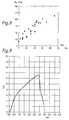
- Figure 7 shows a plot of mean pressure (pm) as a function of effective pressure (pe) obtained on the apparatus of Figure 6;
- Figure 8 shows a corresponding plot to Figure 7 but obtained by the prior art triaxial testing method; and
- Figure 9 shows a specific example of a load (kN)/penetration plot (mm) obtained in the apparatus of Figure 6.
- Referring now to Figure 1, the tool shown therein is a downhole tool which can be lowered into the wellbore by a
wireline 10. The wireline connection to the tool and the power supply and communication related electronics are not illustrated for the purpose of clarity and are of a similar design as the ones used with other similar downhole tools. The tool comprises four modules: a pump outmodule 12, twopacker modules penetrometer module 18. The tool can optionally include a unit to measuretool orientation 19. Thepacker modules module 12 comprises apump 20 which is actuated by amotor 22, apressure gauge 24 and thenecessary valves 26. Thepump 20 is used to inflate thepackers penetrometer module 18. - The
penetrometer module 18 is mounted between the twopacker modules penetrometer module 18 is essentially composed ofunits 28 of indentors. A unit can be composed of one indentor extending into anactuator chamber 34 and an anchor mounted diametrically opposite to the indentor, two indentors mounted diametrically opposite each other, or four indentors mounted at right angles to each other. These designs are required to equilibrate the loads. The displacement of each indentor is measured using anLVDT 32 or other displacement caliper which can also measure the distance between the tool and the borewall. The pressure which is required to displace the indentors into the rock is applied at the same time to the complete set of indentors. The pressure is preferably increased by imposing a constant displacement to thepump 20 and is measured by thepressure gauge 24 in the pump outmodule 12. Atooth 30 of given shape is mounted on the indentor. The tooth can have the shape of a wedge or a cone and preferably includes a flat (not shown) in order to enable the measurement rock elasticity. The pressure in the chamber versus the displacement of the indentors is recorded during the increase of pressure in thechamber 34. Thevalves 24 comprise four remotely operable valves 24a-d which allow communication of thepump 20 with the annulus A, thepacker modules - The determination of the cohesion and angle of internal friction angle is based on the interpretation of the load penetration curves which are obtained during the rock indentation. In order to quantify the indentation response the mean pressure pm which is acting normal to the original specimen surface is used. The mean pressure has been defined for ideal plastic materials which exhibit a linear load penetration curve when indented by a sharp wedge. For these materials, the mean pressure is:

where:
F(u) is the load;
S(u) is the tooth cross section at the original specimen surface (Figure 3). S(u) is a function of the displacement and the geometry of the tooth. For example, for a wedge shaped tooth S is given by:
where:
u is the depth of penetration;
α is the semi-angle of the wedge;
w is the width of the wedge. - However, in rocks the load penetration curve is composed of loading sections and unloading sections (Figure 4). The last section corresponds to the formation of chips of the rock and cannot be used to measure the rock cohesion and friction of internal angle. To keep the notion of measuring a plastic deformation, we define the mean pressure as:

on the loading portions where the mean pressure is constant (Figure 5). The mean pressure has the dimensions of hardness and the value is identified to the relevant rock strength parameters with the help of a plastic model: for example, for a rock which follows a Mohr-Coulomb failure behaviour the mean pressure is given by:
where pmud is the mud pressure and po the pore pressure. G(φ,α) is a known function of the internal friction of the rock and the tooth angle. - Using the Cheatham model (Proc. of 8th Drilling and Blasting Symp., University of Minnesota, 1958, 1A-22A, and Trans. A. I. M. E., 232 pp II-327 II-332.) of a wedge with a rough tooth-rock interface provides a satisfactory description of rocks and gives:

where
The value of pm is measured at two different values of mud pressure. At the loading rate achieved by the equipment, po will remain constant during the test, therefore one obtains:
This formula, once inverted, allows the determination of the value of φ. Once φ is known, c is easily obtained. - The behaviour of the apparatus according to the present invention can be determined from the experimental rig shown in Figure 6.
- In the test rig shown in Figure 6, an indentation cell is used to indent shale samples at displacement rates up to 1 mm/min. This equipment comprises a 60
MPa cell 40, a 200 kN Instron mechanical load frame (not shown), a servo-controlled confiningpressure system 42 and a servo-controlledpore pressure system 44. A step-motor pump (not shown) is used to control the pore pressure and has a displaced volume of 5 ml. The cell allows application of confining pressure (ie the simulated mud pressure) and pore pressure up to 60 MPa to a 6 inch diameter sample. With this cell the simulated mud pressure is equal to the confining pressure. The cell is mounted into the Instron load frame which is used to apply a load to arod 46 on which is attached atooth 48. Experiments are performed at a constant displacement rate and HP 9836 computer is used to control the load frame and to acquire data during the test. The tooth can be attached to the rod eccentrically allowing up to eight indents into the rock to be performed by rotation of the rod, without dismounting the sample or releasing the pressure. During the test the volume of the rod which is inside the cell increases. Therefore, the servo-controlledsystem 42 for the confining pressure must remove some confining fluid to maintain a constant confining pressure. The specimens of 2 inches and 6 inches in diameter are cored from pieces of shale which have been stored under tap water, using diamond core barrels with water lubrication. Coring is done perpendicular to the bedding plane to provide a rock surface to be indented parallel to these bedding planes. The samples are then cut and the tests prepared. - A specific test example is shown in Figure 7 and due to the large number of data available a linear regression technique is used. pe is the effective pressure i.e. the mud pressure minus the pore pressure and pm the mean pressure in MPa. The tooth angle is 40 degree and the tooth width is 10 mm.
- From this example it is found that:

Using the Cheatham solution it is found that φ = 26 degree and c = 6 MPa, which compares well with a determination using triaxial tests which were carried out on the same lithology (a jurassic shale) which gave φ = 22 +/- 2 degree and c = 8 +/- 3 MPa (Figure 8). In this Figure, the peak strength is plotted as a function of effective pressure. The uniaxial strength Cu is the value of peak strength at zero confining pressure and the cohesion c is found from:
It often happens that the pore pressure is unknown. It should be recognized that, in the theory of elasticity, an increase of the mud pressure in the well should not generate a change in the value of the pore pressure, hence the determination of φ proposed in the previous section remains valid. This is particularly true in permeable rocks for which a drilling mud cake builds up, preventing the mud penetrating the formation. If a knowledge of the cohesion is required, a decrease of the mud pressure in the test interval will result in the destruction of the mud cake and the invasion of the formation fluid in the test interval. The mud pressure becomes equal to the pore pressure near the well bore and the term pmud- po cancelled out, allowing the cohesion to be measured. - The situation is more complex in low permeability shales for which a mud cake does not build up or is inefficient. A variation of the mud pressure could also produce an instantaneous variation of the pore pressure near the well bore in plastic rocks. Under this condition the value of the pore pressure near the wellbore is not necessarily the far-field pore pressure but is a combination of the far field pore pressure, the mud pressure, the distance from the wellbore and the time. Therefore the pore pressure is an unknown and the indentation response is going to be used to estimate the value of the pore pressure. The use of a packer arrangement is not required in this situation.
- The approach which is taken is to assume a default value of the friction angle for the shale under consideration, because it has been observed that in most of the cases the friction angle for shales lies between 20 and 25 degrees. Estimation of the friction angle from the drilling response could also be used. Indentation as soon as possible after the formation has been drilled (less than two hours) and up to a reasonable depth (say 5 cm) is also recommended to minimize the effect of mud invasion in shale. Knowledge of the azimuthal direction of the indentation is also recommended because it may be possible to observe an azimuthal variation of indentation response. This variation will be related to the azimuthal variation of the pore pressure which is generated during the creation of the hole when the far-field state of stress is not isotropic (see E Detournay and A Cheng, "Poro-elastic Response of a Borehole in a Non-hydrostatic Stress Field", Int. J. Rock Mechanics,
Vol 25, 3, 1988). However the strength of the azimuthal variation should decay with time. - With an assumption on the value of the angle of internal friction, the indentation response becomes a linear function of the pore pressure and the cohesion. Indentation responses obtained at various depths in the same lithology will show large variation of the cohesion. This is typically the case of the experimental data shown on Figure 7. The scattering of the data which is observed on this Figure is essentially due to a local variation of the cohesion rather than to a local variation of the friction angle (the scattering of the data does not increase with the value of the effective pressure). In order to recover the actual value of the cohesion and in-situ pore pressure, linear optimisation techniques on the set of indentation responses are carried out. The technique of linear programming which is described in "Numerical Recipe" by W H Press et al is considered appropriate. This technique maximizes (or minimizes) a function subject to given constraints. It requires the variables to be positive, which is the case as the cohesion and the pore pressure are always positive. The function to minimize is the sum of the predicted responses minus the sum of the indentation response:

in which i means a given penetration. - If the set of indentations are performed within a 5 feet interval, the pore pressure can be assumed to be constant (5 feet produced a variation of pore pressure of the order of 2 psi; this is negligible compared to the actual value of the pore pressure, which is of the order of 1000s of psi. Thus:

For the particular problem, the additional constraints are a pore pressure ranging from the hydrostatic pressure to the overburden, an estimated maximum value of the cohesion, and the values of the indentation response at each depth. The optimisation gives the value of the cohesions c(i) and the value of the pore pressure. Actually φ could also be entered as an unknown in the optimisation technique. However, non-linear optimisation techniques have then to be used. - The constraints imposed in the technique could be more severe if the rock type is known. To improve the accuracy of the determination especially when the internal angle of friction may not be assumed constant other relationships could be used. For example it has been found that within the same lithology the cohesion of a shale is a function of the porosity. Therefore the following relationship:

can be used where Φ is the porosity obtained from a wireline log and k and ko are constants which have to be determined. In the above equation Φ can be replaced by the Young's modulus of the rock which can be determined directly by the indentor:
For this determination, the relationship between the load and the penetration obtained during an elastic deformation is used. For example, if the tooth has a flat, the load is elastically linearly related to the displacement at the beginning of the loading (Figure 9). The slope is a linear function of the inverse of the Young's modulus. - Figure 9 represents the load penetration curve obtained from Richemont Limestone b43 for a 40° 4 mm blunt indentor extended at 100 mm/min.
- As will be appreciated from the above, for the determination of the parameters of interest generally requires knowledge of one parameter so that the then two can be derived from the results and the formulae given above. Generally, it is the pore pressure po which is known or which can be estimated from observations at other times or locations which are similar to the case under investigation. Alternatively, an estimated value for one parameter can be used which can still give results of sufficient accuracy.


Claims (8)
- A downhole penetrometer comprising a tool body which can be lowered into a borehole, said tool body including a tooth member (30) and an associated fluid pressure operated actuator (34) for moving the tooth member (30) radially outwardly from the body, sensing means for determining the force (24) applied to the tooth member (30) by the actuator (34) and for determining the amount of movement (32) of the tooth member (30), and pumping means (20,22), being provided for supplying pressurised fluid to the actuator (34), the tooth member (30) being moveable so as to penetrate the wall of the borehole and the sensing means (32) determining the extent of penetration of the tooth member (30) into the wall of the borehole,characterised in that the tool body includes the pumping means (20,22), a pair of packers (14,16) which, when inflated in the borehole define a test interval (T), and valves (26a,b,c,d) operable to allow communication between the pumping means (20,22) and the packers (14,16), test interval (T), actuator (34) and borehole respectively.
- A penetrometer as claimed in claim 1, wherein the pumping means (20,22) is provided with means (26d) to maintain the isolated region at a different pressure to the remainder of the borehole.
- A penetrometer as claimed in claim 1 or 2, wherein a pressure sensor (24) is provided to monitor the pressure of fluid provided to the actuator (34) in order to determine the force applied to the tooth (30).
- A penetrometer as claimed in any preceding claim, wherein one or more locating members are provided to engage the borehole wall and to maintain the body in a substantially central position in the borehole.
- A penetrometer as claimed in claim 4, wherein the one or more locating members are further tooth members (30) with associated actuators (34) and means are provided to measure the force applied and the extension of each tooth member.
- A penetrometer as claimed in any preceding claim, wherein the body is provided with a connection from a wireline (10) to communicate directly to the surface in use.
- A penetrometer as claimed in any preceding claim, wherein the or each tooth member (20) is wedge or cone shaped.
- A penetrometer as claimed in any preceding claim, further including a sensor (19) for measuring the orientation of the body.
Applications Claiming Priority (2)
| Application Number | Priority Date | Filing Date | Title |
|---|---|---|---|
| GB9026846 | 1990-12-11 | ||
| GB909026846AGB9026846D0 (en) | 1990-12-11 | 1990-12-11 | Downhole penetrometer |
Publications (3)
| Publication Number | Publication Date |
|---|---|
| EP0490420A2 EP0490420A2 (en) | 1992-06-17 |
| EP0490420A3 EP0490420A3 (en) | 1993-03-03 |
| EP0490420B1true EP0490420B1 (en) | 1995-04-19 |
Family
ID=10686797
Family Applications (1)
| Application Number | Title | Priority Date | Filing Date |
|---|---|---|---|
| EP91203097AExpired - LifetimeEP0490420B1 (en) | 1990-12-11 | 1991-11-27 | Downhole penetrometer |
Country Status (6)
| Country | Link |
|---|---|
| US (1) | US5165274A (en) |
| EP (1) | EP0490420B1 (en) |
| CA (1) | CA2056965A1 (en) |
| DE (1) | DE69109068D1 (en) |
| GB (2) | GB9026846D0 (en) |
| NO (1) | NO914862L (en) |
Cited By (1)
| Publication number | Priority date | Publication date | Assignee | Title |
|---|---|---|---|---|
| US12180806B2 (en) | 2020-11-12 | 2024-12-31 | Moog Inc. | Subsurface safety valve actuator |
Families Citing this family (39)
| Publication number | Priority date | Publication date | Assignee | Title |
|---|---|---|---|---|
| GB9204902D0 (en)* | 1992-03-06 | 1992-04-22 | Schlumberger Ltd | Formation evalution tool |
| US5287741A (en)* | 1992-08-31 | 1994-02-22 | Halliburton Company | Methods of perforating and testing wells using coiled tubing |
| US5282384A (en)* | 1992-10-05 | 1994-02-01 | Baroid Technology, Inc. | Method for calculating sedimentary rock pore pressure |
| US5743334A (en)* | 1996-04-04 | 1998-04-28 | Chevron U.S.A. Inc. | Evaluating a hydraulic fracture treatment in a wellbore |
| US6134954A (en) | 1996-04-15 | 2000-10-24 | Massachusetts Institute Of Technology | Depth sensing indentation and methodology for mechanical property measurements |
| US5999887A (en)* | 1997-02-26 | 1999-12-07 | Massachusetts Institute Of Technology | Method and apparatus for determination of mechanical properties of functionally-graded materials |
| US6641893B1 (en) | 1997-03-14 | 2003-11-04 | Massachusetts Institute Of Technology | Functionally-graded materials and the engineering of tribological resistance at surfaces |
| US6691779B1 (en) | 1997-06-02 | 2004-02-17 | Schlumberger Technology Corporation | Wellbore antennae system and method |
| US6234257B1 (en)* | 1997-06-02 | 2001-05-22 | Schlumberger Technology Corporation | Deployable sensor apparatus and method |
| US6766854B2 (en) | 1997-06-02 | 2004-07-27 | Schlumberger Technology Corporation | Well-bore sensor apparatus and method |
| US6464021B1 (en) | 1997-06-02 | 2002-10-15 | Schlumberger Technology Corporation | Equi-pressure geosteering |
| US6028534A (en)* | 1997-06-02 | 2000-02-22 | Schlumberger Technology Corporation | Formation data sensing with deployed remote sensors during well drilling |
| US6693553B1 (en) | 1997-06-02 | 2004-02-17 | Schlumberger Technology Corporation | Reservoir management system and method |
| US6070662A (en)* | 1998-08-18 | 2000-06-06 | Schlumberger Technology Corporation | Formation pressure measurement with remote sensors in cased boreholes |
| US6230557B1 (en) | 1998-08-04 | 2001-05-15 | Schlumberger Technology Corporation | Formation pressure measurement while drilling utilizing a non-rotating sleeve |
| US6553852B1 (en) | 1999-10-22 | 2003-04-29 | Westinghouse Savannah River Company, L.L.C. | Apparatus and process for an off-surface cone penetrometer sensor |
| US6467387B1 (en) | 2000-08-25 | 2002-10-22 | Schlumberger Technology Corporation | Apparatus and method for propelling a data sensing apparatus into a subsurface formation |
| EP1352151B1 (en)* | 2001-01-18 | 2004-10-06 | Shell Internationale Researchmaatschappij B.V. | Measuring the in situ static formation temperature |
| US6769296B2 (en) | 2001-06-13 | 2004-08-03 | Schlumberger Technology Corporation | Apparatus and method for measuring formation pressure using a nozzle |
| GB2398640B (en)* | 2001-11-19 | 2005-06-22 | Schlumberger Holdings | Downhole measurement apparatus and technique |
| US7000697B2 (en) | 2001-11-19 | 2006-02-21 | Schlumberger Technology Corporation | Downhole measurement apparatus and technique |
| US20040237640A1 (en)* | 2003-05-29 | 2004-12-02 | Baker Hughes, Incorporated | Method and apparatus for measuring in-situ rock moduli and strength |
| WO2008033120A2 (en)* | 2006-09-12 | 2008-03-20 | Halliburton Energy Services, Inc. | Method and apparatus for perforating and isolating perforations in a wellbore |
| MX2009007808A (en)* | 2007-02-07 | 2009-07-30 | Schlumberger Technology Bv | Downhole rock scratcher and method for identifying strength of subsurface intervals. |
| US8141419B2 (en)* | 2007-11-27 | 2012-03-27 | Baker Hughes Incorporated | In-situ formation strength testing |
| US20090164128A1 (en)* | 2007-11-27 | 2009-06-25 | Baker Hughes Incorporated | In-situ formation strength testing with formation sampling |
| US8171990B2 (en)* | 2007-11-27 | 2012-05-08 | Baker Hughes Incorporated | In-situ formation strength testing with coring |
| US8146418B2 (en)* | 2008-09-02 | 2012-04-03 | Keppel Offshore & Marie Technology Centre Pte Ltd | Apparatus and method for soil testing for jack-up rigs |
| NL2004684C2 (en)* | 2010-05-07 | 2011-11-08 | Gouda Geo Equipment B V | Cone penetration testing pushing device and system. |
| US9062544B2 (en) | 2011-11-16 | 2015-06-23 | Schlumberger Technology Corporation | Formation fracturing |
| US9482087B2 (en)* | 2012-04-13 | 2016-11-01 | Schlumberger Technology Corporation | Geomechanical logging tool |
| WO2014149048A1 (en) | 2013-03-21 | 2014-09-25 | Halliburton Energy Services, Inc. | In-situ geo-mechanical testing |
| US10001433B2 (en)* | 2014-12-19 | 2018-06-19 | Halliburton Energy Services, Inc. | Method for rockwell hardness testing of tubulars post wellbore installation |
| CN105022902B (en)* | 2015-08-21 | 2017-11-10 | 青岛理工大学 | Concrete material damage prediction method based on over-king damage criterion |
| ITUA20164208A1 (en)* | 2016-06-08 | 2017-12-08 | Univ Bologna Alma Mater Studiorum | INSTRUMENT FOR VERIFYING THE SATURATION DEGREE OF A PRESSURE SENSOR GROUP OF A PIEZOCONO, AND METHOD FOR CARRYING OUT THIS VERIFICATION |
| US11702911B2 (en)* | 2018-12-17 | 2023-07-18 | Schlumberger Technology Corporation | System and method for mechanical tubing puncher |
| US12050297B2 (en) | 2020-09-11 | 2024-07-30 | Saudi Arabian Oil Company | Method and system for determining energy-based brittleness |
| US11867053B2 (en)* | 2020-11-25 | 2024-01-09 | Saudi Arabian Oil Company | Shear head device |
| US20240344455A1 (en)* | 2023-04-14 | 2024-10-17 | Halliburton Energy Services, Inc. | Wellbore probe movement control |
Citations (1)
| Publication number | Priority date | Publication date | Assignee | Title |
|---|---|---|---|---|
| US3115775A (en)* | 1960-01-06 | 1963-12-31 | William L Russell | Method and apparatus for measuring the pressures of fluids in subsurface rocks |
Family Cites Families (16)
| Publication number | Priority date | Publication date | Assignee | Title |
|---|---|---|---|---|
| DE845425C (en)* | 1951-01-19 | 1952-07-31 | Kohlenbergbau Leitung Deutsche | Process for measuring the carbon strength and equipment for carrying out the process |
| US2957341A (en)* | 1956-01-16 | 1960-10-25 | Menard Louis Francois Auguste | Soil testing apparatus |
| US2927459A (en)* | 1957-07-18 | 1960-03-08 | Jersey Prod Res Co | Measurement of subsurface stress |
| US3872717A (en)* | 1972-01-03 | 1975-03-25 | Nathaniel S Fox | Soil testing method and apparatus |
| US3785200A (en)* | 1972-06-01 | 1974-01-15 | Univ Iowa State Res Found Inc | Apparatus for in situ borehole testing |
| US3934468A (en)* | 1975-01-22 | 1976-01-27 | Schlumberger Technology Corporation | Formation-testing apparatus |
| SU567993A1 (en)* | 1975-03-28 | 1977-08-05 | Ордена Октябрьской Революции Всесоюзный Государственный Проектно-Изыскательский И Научно-Исследовательский Институт По Проектированию Энергетических Систем И Электрических Сетей "Энергосетьпроект" | Device for investigating mechanical properties of soils in a borehole |
| US3961524A (en)* | 1975-05-06 | 1976-06-08 | The United States Of America As Represented By The Secretary Of The Interior | Method and apparatus for determining rock stress in situ |
| US4149409A (en)* | 1977-11-14 | 1979-04-17 | Shosei Serata | Borehole stress property measuring system |
| JPS57123319A (en)* | 1981-01-22 | 1982-07-31 | Kiso Jiban Consultant Kk | Method and apparatus for subsurface exploration |
| US4461171A (en)* | 1983-01-13 | 1984-07-24 | Wisconsin Alumni Research Foundation | Method and apparatus for determining the in situ deformability of rock masses |
| US4899320A (en)* | 1985-07-05 | 1990-02-06 | Atlantic Richfield Company | Downhole tool for determining in-situ formation stress orientation |
| US4843878A (en)* | 1988-09-22 | 1989-07-04 | Halliburton Logging Services, Inc. | Method and apparatus for instantaneously indicating permeability and horner plot slope relating to formation testing |
| US4860581A (en)* | 1988-09-23 | 1989-08-29 | Schlumberger Technology Corporation | Down hole tool for determination of formation properties |
| US4936139A (en)* | 1988-09-23 | 1990-06-26 | Schlumberger Technology Corporation | Down hole method for determination of formation properties |
| US5042595A (en)* | 1990-02-05 | 1991-08-27 | La Corporation De L'ecole Polytechnique | Method and device for in-situ determination of rheological properties of earth materials |
- 1990
- 1990-12-11GBGB909026846Apatent/GB9026846D0/enactivePending
- 1991
- 1991-11-27GBGB9125195Apatent/GB2250826B/ennot_activeExpired - Fee Related
- 1991-11-27DEDE69109068Tpatent/DE69109068D1/ennot_activeExpired - Lifetime
- 1991-11-27EPEP91203097Apatent/EP0490420B1/ennot_activeExpired - Lifetime
- 1991-12-04USUS07/802,382patent/US5165274A/ennot_activeExpired - Lifetime
- 1991-12-04CACA002056965Apatent/CA2056965A1/ennot_activeAbandoned
- 1991-12-10NONO91914862Apatent/NO914862L/enunknown
Patent Citations (1)
| Publication number | Priority date | Publication date | Assignee | Title |
|---|---|---|---|---|
| US3115775A (en)* | 1960-01-06 | 1963-12-31 | William L Russell | Method and apparatus for measuring the pressures of fluids in subsurface rocks |
Cited By (1)
| Publication number | Priority date | Publication date | Assignee | Title |
|---|---|---|---|---|
| US12180806B2 (en) | 2020-11-12 | 2024-12-31 | Moog Inc. | Subsurface safety valve actuator |
Also Published As
| Publication number | Publication date |
|---|---|
| GB9026846D0 (en) | 1991-01-30 |
| US5165274A (en) | 1992-11-24 |
| DE69109068D1 (en) | 1995-05-24 |
| NO914862L (en) | 1992-06-12 |
| GB9125195D0 (en) | 1992-01-29 |
| CA2056965A1 (en) | 1992-06-12 |
| EP0490420A2 (en) | 1992-06-17 |
| EP0490420A3 (en) | 1993-03-03 |
| GB2250826B (en) | 1994-06-01 |
| NO914862D0 (en) | 1991-12-10 |
| GB2250826A (en) | 1992-06-17 |
Similar Documents
| Publication | Publication Date | Title |
|---|---|---|
| EP0490420B1 (en) | Downhole penetrometer | |
| US5517854A (en) | Methods and apparatus for borehole measurement of formation stress | |
| O'Neill | Side resistance in piles and drilled shafts | |
| Li et al. | Application of resonance enhanced drilling to coring | |
| EP3346092B1 (en) | In-situ geo-mechanical testing | |
| US7753118B2 (en) | Method and tool for evaluating fluid dynamic properties of a cement annulus surrounding a casing | |
| Thiercelin et al. | A new wireline tool for in-situ stress measurements | |
| EP3947909B1 (en) | System and method for evaluating static elastic modulus of subterranean formation | |
| Steiger et al. | Lecture: Predictions of wellbore stability in shale formations at great depth | |
| US20180328827A1 (en) | Wellbore material continuous hardness testing methods and tools | |
| US5511615A (en) | Method and apparatus for in-situ borehole stress determination | |
| Schmitt et al. | Hydraulic fracturing stress measurements in deep holes | |
| Trzeciak et al. | Laboratory evaluation of the thermal breakout method for maximum horizontal stress measurement | |
| Harper et al. | The nature and determination of stress in the accessible lithosphere | |
| Davies et al. | Determination of geomechanical properties of a typical Niger Delta reservoir rock using geophysical well logs | |
| Haimson | Borehole breakouts in crystalline and granular rocks as indicators of in situ stress | |
| Wood | Wellbore stability and the establishment of a safe mud weight window | |
| Fjær et al. | Mechanical properties and stress data from laboratory analysis | |
| McLennan et al. | Hydraulic fracturing experiment at the University of Regina Campus | |
| Skopec | Recent advances in rock characterization | |
| Skopec | Rock characterization in reservoirs targeted for horizontal drilling | |
| Amadei et al. | Methods of in situ stress measurement | |
| Admassu | Rock Field Tests | |
| Roegiers | The petroleum approach to the state of in-situ stress | |
| Fjær et al. | Mechanical properties and in situ stresses from field data |
Legal Events
| Date | Code | Title | Description |
|---|---|---|---|
| PUAI | Public reference made under article 153(3) epc to a published international application that has entered the european phase | Free format text:ORIGINAL CODE: 0009012 | |
| AK | Designated contracting states | Kind code of ref document:A2 Designated state(s):DE DK FR IT NL | |
| PUAL | Search report despatched | Free format text:ORIGINAL CODE: 0009013 | |
| AK | Designated contracting states | Kind code of ref document:A3 Designated state(s):DE DK FR IT NL | |
| 17P | Request for examination filed | Effective date:19930316 | |
| 17Q | First examination report despatched | Effective date:19930818 | |
| GRAA | (expected) grant | Free format text:ORIGINAL CODE: 0009210 | |
| AK | Designated contracting states | Kind code of ref document:B1 Designated state(s):DE DK FR IT NL | |
| PG25 | Lapsed in a contracting state [announced via postgrant information from national office to epo] | Ref country code:IT Free format text:LAPSE BECAUSE OF FAILURE TO SUBMIT A TRANSLATION OF THE DESCRIPTION OR TO PAY THE FEE WITHIN THE PRESCRIBED TIME-LIMIT;WARNING: LAPSES OF ITALIAN PATENTS WITH EFFECTIVE DATE BEFORE 2007 MAY HAVE OCCURRED AT ANY TIME BEFORE 2007. THE CORRECT EFFECTIVE DATE MAY BE DIFFERENT FROM THE ONE RECORDED. Effective date:19950419 Ref country code:NL Free format text:LAPSE BECAUSE OF NON-PAYMENT OF DUE FEES Effective date:19950419 Ref country code:DK Effective date:19950419 | |
| REF | Corresponds to: | Ref document number:69109068 Country of ref document:DE Date of ref document:19950524 | |
| PG25 | Lapsed in a contracting state [announced via postgrant information from national office to epo] | Ref country code:DE Effective date:19950720 | |
| ET | Fr: translation filed | ||
| NLV1 | Nl: lapsed or annulled due to failure to fulfill the requirements of art. 29p and 29m of the patents act | ||
| PLBE | No opposition filed within time limit | Free format text:ORIGINAL CODE: 0009261 | |
| STAA | Information on the status of an ep patent application or granted ep patent | Free format text:STATUS: NO OPPOSITION FILED WITHIN TIME LIMIT | |
| 26N | No opposition filed | ||
| PGFP | Annual fee paid to national office [announced via postgrant information from national office to epo] | Ref country code:FR Payment date:20031110 Year of fee payment:13 | |
| PG25 | Lapsed in a contracting state [announced via postgrant information from national office to epo] | Ref country code:FR Free format text:LAPSE BECAUSE OF NON-PAYMENT OF DUE FEES Effective date:20050729 | |
| REG | Reference to a national code | Ref country code:FR Ref legal event code:ST |