EP0488888A1 - Method and apparatus for reconstructing three-dimensional images of an object using two common-axis circular paths - Google Patents
Method and apparatus for reconstructing three-dimensional images of an object using two common-axis circular pathsDownload PDFInfo
- Publication number
- EP0488888A1 EP0488888A1EP91403213AEP91403213AEP0488888A1EP 0488888 A1EP0488888 A1EP 0488888A1EP 91403213 AEP91403213 AEP 91403213AEP 91403213 AEP91403213 AEP 91403213AEP 0488888 A1EP0488888 A1EP 0488888A1
- Authority
- EP
- European Patent Office
- Prior art keywords
- measurements
- function
- reconstructing
- series
- dimensional images
- Prior art date
- Legal status (The legal status is an assumption and is not a legal conclusion. Google has not performed a legal analysis and makes no representation as to the accuracy of the status listed.)
- Granted
Links
Images

Classifications
- G—PHYSICS
- G06—COMPUTING OR CALCULATING; COUNTING
- G06T—IMAGE DATA PROCESSING OR GENERATION, IN GENERAL
- G06T11/00—2D [Two Dimensional] image generation
- G06T11/003—Reconstruction from projections, e.g. tomography
- G06T11/006—Inverse problem, transformation from projection-space into object-space, e.g. transform methods, back-projection, algebraic methods
- A—HUMAN NECESSITIES
- A61—MEDICAL OR VETERINARY SCIENCE; HYGIENE
- A61B—DIAGNOSIS; SURGERY; IDENTIFICATION
- A61B6/00—Apparatus or devices for radiation diagnosis; Apparatus or devices for radiation diagnosis combined with radiation therapy equipment
- A61B6/02—Arrangements for diagnosis sequentially in different planes; Stereoscopic radiation diagnosis
- A61B6/027—Arrangements for diagnosis sequentially in different planes; Stereoscopic radiation diagnosis characterised by the use of a particular data acquisition trajectory, e.g. helical or spiral
Definitions
- the inventionrelates to a method and a device for reconstructing three-dimensional images of an object which comprises measurements on two circular trajectories of common axis, that is to say that the trajectories belong to parallel planes and their centers are joined by an axis perpendicular to the plane of the trajectories. If the planes of the trajectories are confused, they are concentric. We can also envisage more numerous trajectories.
- the reconstruction of the imagesconcerns an object determined to be examined, and the material means employed comprise two two-dimensional networks of sensors each traversing one of the trajectories or, equivalently, a single network which traverses all the trajectories.
- the image of the objectis defined by values taken by a function on each of its points.
- the functionis on the other hand a property of a radiation (X or gamma among others) of conical shape having a focal point and which passes through the object; each ray is received by one of the two-dimensional network sensors and therefore represents the sum of the function on all the points of the object belonging to this ray. Appropriate processing of the sums on all the spokes, and this for a sufficient number of measurements according to different incidences around the object, makes it possible to reconstruct the image of the object.
- This inventionconstitutes an improvement on a previous invention, described in European patent application EP-A-0 292 402, but it is possible to envisage using the present invention in other circumstances or by using other mathematical methods. of data processing.
- the possible methodsuse in particular what is called the Radon transform of the function to be measured, which is defined as the sum of the function on each of the planes, called Radon planes, which pass through the object under consideration or, better still, the primary derivative of this transform.
- the contribution of the points of these planes which do not belong to the objectis considered to be nonexistent, which is valid in the case of radiation which crosses an ambient gaseous medium without being attenuated.
- a discretizationis carried out in order to perform the calculations only on a finite number of planes.
- the first derivative of the Radon transformis defined as the derivative of the Radon transform as a function of the variable ⁇ defining the distance from the plane considered to an origin. For each plane, it corresponds to the sum on this plane of the first derivative of the Radon transform in the direction perpendicular to the plane.
- the invention described in patent EP-A-0 292 402shows that for a plane passing through a position of the focal point of the radiation cone and meeting the two-dimensional array of sensors, it is possible to calculate from the measurements the exact value of the first derivative of the Radon transform on this plane.
- This calculationpreferably uses a weighting for correction of the distance from the focal point, two filterings corresponding to the calculations of the first derivatives respectively along the rows and columns of the sensor network, two summations along the line of intersection between the plane to be treated and the two-dimensional network of sensors, then a linear combination and a normalization of the results.
- This summationimplements the necessary interpolations because these intersection lines pass between the rows of sensors or cut them.
- the term “sum”is understood to mean the weighted sum of the measured values (in the case of the Radon transform) as well as the linear combination of the sums of the weighted and filtered values (in the case of the first derivative of the Radon transform) obtained according to the rows and columns of the network.
- Each Radon planecan be defined by what is called its characteristic point, that is to say the point of projection onto this plane of an origin O chosen arbitrarily.
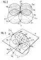
- This characteristic point, noted C in FIG. 1can be defined by its spherical coordinates ⁇ , ⁇ and ⁇ of radius, longitude and colatitude respectively from the origin O.
- the plane of Radon P passing through the characteristic point Ccan be defined by the radius ⁇ and the unit vector of management
- the values of the function on the Radon planescan effectively be calculated only for the Radon planes which intersect the path traveled by the focal point of the radiation.
- This focal pointis concretely, in the case of an attenuation function, a point source of X-rays, gamma rays, etc. This is the design which is described in the mentioned European patent application.
- the focal pointthen has no physical existence and simply corresponds to the point of convergence towards which all the collimators used in front of the two-dimensional network are directed.
- the focal point (or the source) Sthe plane array of sensors Pdet traversing the same trajectory as the focal point S or possibly a concentric trajectory of different radius.
- the origin O which is used to define the characteristic points Cis located on the axis of the trajectory T.
- the volume enveloping the characteristic pointscorresponds to a torus To produced by the rotation of a spherical surface of diameter OS around the axis of rotation of the trajectory T.
- the planes of Radon which pass through the focal point Shave their characteristic points distributed on the spherical surface of diameter OS because l SCO angle is right.
- the torus Tois called the characteristic volume of the measurements, which therefore depends on the shape of the trajectory T and its position relative to the origin O.
- the essential object of the inventionis to facilitate reconstructions by making them faster if several measurement chains are used, which makes it possible to reduce the duration of examinations, in medical imaging where the patient must remain immobile and in non-destructive testing. where we are constrained to work rates; or again, the method makes it possible to deal with cases where each acquisition chain is defined by its own parameters and in particular the case where the two centers of the trajectories of two acquisition chains are close but distinct for mechanical reasons. It is then the quality of the images which is improved. Finally, when the two circular paths are on either side of the object, the shadow area can be reduced and the image improved here again.
- the superimposition of several trajectoriesalso increases the characteristic volume of measurements and allows the examination of larger objects. However, in all cases we encounter calculation difficulties because the grouping of acquisitions made over several trajectories requires conversions using mathematical operations because of the parameterization of each series of measurements by specific characteristic coefficients.
- the mechanical inaccuracies on the real orientation of the sensors, the real radii of their trajectory and of the focal point, etc.result in additional calculations and interpolations when the benchmark changes are made to group the results of the measurement series.
- the image reconstruction informationis therefore degraded. If, on the other hand, the method according to the invention is used, the parameters of the trajectories and series of measurements, which integrate the mechanical inaccuracies and have been measured during preliminary calibrations of the machine, are used directly in the benchmark used for reconstruct the object, whose images will then be reconstructed with better clarity.
- the inventionis therefore based on the observation that, if a common coordinate system is defined to configure the characteristic trajectories and volumes, no coordinate conversion or change of coordinate system is necessary to merge or group the results from different trajectories.
- a common coordinate systemis defined to configure the characteristic trajectories and volumes, no coordinate conversion or change of coordinate system is necessary to merge or group the results from different trajectories.
- such a procedureis easy if the trajectories are coaxial.
- the inventionis, to summarize, relating to a method of reconstructing three-dimensional images of an object defined by values taken by a function on points of the object, the function being a property of a conical radiation having a focal point and passing through the object, in which the function is calculated by means of sums of the function on planes passing through at least one point of the object and defined in an object reference, comprising at least two series of measurements, each sum of the function on said planes configured in the object reference being calculated from at least one of the series of measurements, each of the series of measurements being carried out with a two-dimensional network of radiation sensors, oriented towards the focal point, and which is moved around the object on a respective circular trajectory, characterized in that the trajectories have centers joined by an axis perpendicular to the trajectories, are defined, as well as the object, by a relation to an object reference, in that, for each series of measurements, a series of sums of the function is calculated in this object reference for the secant planes or tangents to an
- the object referencehas an axis coincident with the axis perpendicular to the trajectories.
- the coordinates usedare advantageously spherical.
- the inventionalso relates to devices specially designed for implementing the method.
- the characteristic volume of the measurementsthat is to say the set of characteristic points of the Radon planes defined from the origin O, is again a torus To1 generated by rotating a spherical surface of diameter OS1 along the trajectory T1 and around of origin O.
- the torus To1has a complex shape since it has a part of intersection I in the center, because the meridian sections of the torus To1 form two circular surfaces which overlap.
- a simple geometric reasoningmakes it possible to be convinced that the planes associated with the points located inside the area of intersection I do not intersect the trajectory and that this part belongs to the area of shadow: the characteristic volume of the measurements represented according to this meridian cut is the hatched one.
- FIG. 3A possible mode for carrying out the method has been shown in FIG. 3.
- ⁇ i⁇ (i-1) + 2 ⁇ not from the X axis.
- We measure for each point Qithe values of the function on the Radon planes whose characteristic points belong to the sphere of diameter OQi.
- the sum of the function on these planescan be calculated from two positions of the focal point because these planes intersect the trajectory T at two points, Q1 and Q5 in the example considered.
- the points W retainedare however points which are regularly defined on a mesh defined in the frame O, X, Y, Z by its regular spherical coordinates (radius ⁇ , longitude ⁇ and colatitude ⁇ ), so that the plane of Radon does not cut the trajectory exactly at the points Q and that approximations or interpolations on the angles ⁇ i are thus necessary, according to the method envisaged in the preceding invention for example.
- the present inventionthere are two measurement chains, each of which performs the measurements simultaneously on a subset of the Q points.
- the two most normal ways of proceedingare either to assign the points of odd order to one and the points of order even with the other, that is to divide the trajectory in two equal halves whose respective points Q are assigned to one of the measurement chains, each subset then comprising half of the points Q. It is still possible that the subsets are larger than half, which will make overlapping possible for some Q points.
- Another ideais to double the measurements at Q points to improve the image quality by a statistical average.
- the regrouping of the series of measurementsconsists for example either in considering alternately the sums of function associated with each series of measurements for the planes meeting the two trajectories of the focal points, or in making their means, or to consider only a sum of associated function when the plane meets only one of the trajectories.
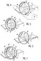
- FIG. 4An appropriate device is shown in FIG. 4. It is a medical tomography installation where the patient is lying on a horizontal table 1.
- a circular rail 2extends in a vertical and transverse plane and surrounds the table 1.
- These trolleyshave been shown diagrammatically and reference may be made, if necessary, to the prior invention for more technical details.
- Eachcarries an X-ray source near a screen carrying a two-dimensional network of sensors. The sensors of the screen 4 are focused on the source 3 of the other mobile carriage, and those of the other screen 4 ′ are focused on the source 3 ′ of the first mobile carriage. Sources 3 and 3 ′ emit a conical beam 5 or 5 ′.
- the object to be examinedis placed in the area of intersection of the cones of the two beams 5 and 5 ′.
- the two mobile carriagesmove simultaneously in rotation so as to remain diametrically opposite.
- the movementsare regulated by the installation control computer.
- the sources 3 and 3 ′would be omitted and the focal point of the sensors of each screen 4 or 4 ′ would advantageously be located in the center of the other screen 4 or 4 ′, to simplify acquisition calculations. It would still be possible to separate the sources 3, 3 ′ from the screens 4, 4 ′ so that the beams 5 and 5 ′ intersect at right angles for example.
- the screens 4 and 4 ′are connected to means for acquiring and processing the measurements generally represented by 6.
- FIG. 5A slightly different design is shown in Figure 5.
- the monile cartsare identical to the previous ones but this time placed on a respective rail 2 or 2 ′.
- the rails 2 and 2 ′are coplanar and concentric. None is modified except for the coefficients of the geometric magnification relations as a function of the distances from sources 3 and 3 ′ and screens 4 and 4 ′ at the origin O.
- the inventioncan be implemented (FIG. 6) with a single rail 2 which carries a single source 3 diametrically opposite to a screen 4 carrying a two-dimensional network of sensors.
- a single rail 2which carries a single source 3 diametrically opposite to a screen 4 carrying a two-dimensional network of sensors.
- two complete turnsare made at the source 3 and the screen 4, between which the table 1 undergoes a translation perpendicular to the plane of the rail 2.
- Such a solutionis used to increase the characteristic volume of the measurements in accordance with l figure 2.
- the inventioncan be implemented in other ways. This is how the angular movement on each circular path can be reduced to a part of the circumference.
- An advantageous caseis that of a complete circumference formed by the union of angular deflections.
- the inventioncan be used for the usual applications of medical imaging or non-destructive testing of parts.
Landscapes
- Engineering & Computer Science (AREA)
- Physics & Mathematics (AREA)
- Life Sciences & Earth Sciences (AREA)
- Health & Medical Sciences (AREA)
- Theoretical Computer Science (AREA)
- General Physics & Mathematics (AREA)
- Medical Informatics (AREA)
- Nuclear Medicine, Radiotherapy & Molecular Imaging (AREA)
- Biomedical Technology (AREA)
- Mathematical Physics (AREA)
- Mathematical Optimization (AREA)
- Biophysics (AREA)
- High Energy & Nuclear Physics (AREA)
- Mathematical Analysis (AREA)
- Algebra (AREA)
- Optics & Photonics (AREA)
- Pathology (AREA)
- Radiology & Medical Imaging (AREA)
- Pure & Applied Mathematics (AREA)
- Heart & Thoracic Surgery (AREA)
- Molecular Biology (AREA)
- Surgery (AREA)
- Animal Behavior & Ethology (AREA)
- General Health & Medical Sciences (AREA)
- Public Health (AREA)
- Veterinary Medicine (AREA)
- Image Processing (AREA)
- Apparatus For Radiation Diagnosis (AREA)
- Image Generation (AREA)
- Image Analysis (AREA)
Abstract
Description
Translated fromFrenchL'invention se rapporte à un procédé et un dispositif de reconstruction d'images tridimensionnelles d'un objet qui comporte des mesures sur deux trajectoires circulaires d'axe commun, c'est-à-dire que les trajectoires appartiennent à des plans parallèles et leurs centres sont joints par un axe perpendiculaire au plan des trajectoires. Si les plans des trajectoires sont confondus, elles sont concentriques. On peut aussi envisager des trajectoires plus nombreuses.The invention relates to a method and a device for reconstructing three-dimensional images of an object which comprises measurements on two circular trajectories of common axis, that is to say that the trajectories belong to parallel planes and their centers are joined by an axis perpendicular to the plane of the trajectories. If the planes of the trajectories are confused, they are concentric. We can also envisage more numerous trajectories.
La reconstruction des images concerne un objet déterminé à examiner, et les moyens matériels employés comportent deux réseaux bidimensionnels de capteurs parcourant chacun une des trajectoires ou, de manière équivalente, un seul réseau qui parcourt toutes les trajectoires.The reconstruction of the images concerns an object determined to be examined, and the material means employed comprise two two-dimensional networks of sensors each traversing one of the trajectories or, equivalently, a single network which traverses all the trajectories.
L'image de l'objet est définie par des valeurs prises par une fonction sur chacun de ses points. La fonction est d'autre part une propriété d'un rayonnement (X ou gamma entre autres) de forme conique ayant un point focal et qui passe à travers l'objet ; chaque rayon est reçu par un des capteurs du réseau bidimensionnel et représente donc la somme de la fonction sur tous les points de l'objet appartenant à ce rayon. Un traitement approprié des sommes sur tous les rayons, et ceci pour un nombre suffisant de mesures suivant des incidences différentes autour de l'objet, permet de reconstituer l'image de l'objet.The image of the object is defined by values taken by a function on each of its points. The function is on the other hand a property of a radiation (X or gamma among others) of conical shape having a focal point and which passes through the object; each ray is received by one of the two-dimensional network sensors and therefore represents the sum of the function on all the points of the object belonging to this ray. Appropriate processing of the sums on all the spokes, and this for a sufficient number of measurements according to different incidences around the object, makes it possible to reconstruct the image of the object.
On se contente en pratique de considérer des nombres finis de rayons et de points de l'objet selon des discrétisations ou des maillages.One is satisfied in practice to consider finite numbers of radii and points of the object according to discretizations or meshes.
Cette invention constitue un perfectionnement d'une invention précédente, décrite dans la demande de brevet européen EP-A-0 292 402, mais on peut envisager d'employer l'invention actuelle dans d'autres circonstances ou en utilisant d'autres méthodes mathématiques de traitement des données.This invention constitutes an improvement on a previous invention, described in European patent application EP-A-0 292 402, but it is possible to envisage using the present invention in other circumstances or by using other mathematical methods. of data processing.
Les méthodes envisageables utilisent en particulier ce qu'on appelle la transformée de Radon de la fonction à mesurer, qui est définie comme la somme de la fonction sur chacun des plans, appelés plans de Radon, qui passent à travers l'objet considéré ou, mieux encore, la dérivée première de cette transformée. La contribution des points de ces plans qui n'appartiennent pas à l'objet est considérée comme inexistante, ce qui est valable dans le cas d'un rayonnement qui traverse un milieu gazeux ambiant sans être atténué. Ici encore, une discrétisation est effectuée pour n'effectuer les calculs que sur un nombre fini de plans.The possible methods use in particular what is called the Radon transform of the function to be measured, which is defined as the sum of the function on each of the planes, called Radon planes, which pass through the object under consideration or, better still, the primary derivative of this transform. The contribution of the points of these planes which do not belong to the object is considered to be nonexistent, which is valid in the case of radiation which crosses an ambient gaseous medium without being attenuated. Here again, a discretization is carried out in order to perform the calculations only on a finite number of planes.
La dérivée première de la transformée de Radon est définie comme la dérivée de la transformée de Radon en fonction de la variable ρ définissant la distance du plan considéré à une origine. Pour chaque plan, elle correspond à la somme sur ce plan de la dérivée première de la transformée de Radon dans la direction perpendiculaire au plan. L'invention décrite dans le brevet EP-A-0 292 402 montre que pour un plan passant par une position du point focal du cône de rayonnement et rencontrant le réseau bidimensionnel de capteurs, il est possible de calculer à partir des mesures la valeur exacte de la dérivée première de la transformée de Radon sur ce plan. Ce calcul, suivant les formules exposées dans le brevet EP-A-0 292 402, met en oeuvre de façon préférentielle une pondération de correction d'éloignement du point focal, deux filtrages correspondant aux calculs des derivées premières respectivement suivant les lignes et les colonnes du réseau de capteurs, deux sommations suivant la droite d'intersection entre le plan à traiter et le réseau bidimensionnel de capteurs, puis une combinaison linéaire et une normalisation des résultats. Cette sommation met en oeuvre les interpolations nécessaires car ces droites d'intersection passent entre les rangées de capteurs ou les coupent.The first derivative of the Radon transform is defined as the derivative of the Radon transform as a function of the variable ρ defining the distance from the plane considered to an origin. For each plane, it corresponds to the sum on this plane of the first derivative of the Radon transform in the direction perpendicular to the plane. The invention described in patent EP-A-0 292 402 shows that for a plane passing through a position of the focal point of the radiation cone and meeting the two-dimensional array of sensors, it is possible to calculate from the measurements the exact value of the first derivative of the Radon transform on this plane. This calculation, according to the formulas set out in patent EP-A-0 292 402, preferably uses a weighting for correction of the distance from the focal point, two filterings corresponding to the calculations of the first derivatives respectively along the rows and columns of the sensor network, two summations along the line of intersection between the plane to be treated and the two-dimensional network of sensors, then a linear combination and a normalization of the results. This summation implements the necessary interpolations because these intersection lines pass between the rows of sensors or cut them.
Dans le reste de la demande, on entend par somme la somme pondérée des valeurs mesurées (dans le cas de la transformée de Radon) aussi bien que la combinaison linéaire des sommes des valeurs pondérées et filtrées (dans le cas de la dérivée première de la transformée de Radon) obtenues selon les lignes et les colonnes du réseau.In the rest of the application, the term “sum” is understood to mean the weighted sum of the measured values (in the case of the Radon transform) as well as the linear combination of the sums of the weighted and filtered values (in the case of the first derivative of the Radon transform) obtained according to the rows and columns of the network.
La somme de la fonction sur les points des plans de Radon est facile à obtenir à condition que ces plans aient une intersection avec le réseau bidimensionnel de capteurs et qu'ils passent par le point focal unique que visent les capteurs. Il suffit d'effectuer la somme des valeurs mesurées par chaque capteur situé à l'intersection, avec les interpolations nécessaires car les intersections des plans de Radon passent entre des rangées de capteurs ou les coupent. Une fois que les valeurs de la fonction sur les plans de Radon ont été calculées, il existe des formules d'inversion, exposées dans la demande de brevet mentionnée ci-dessus, qui permettent de parvenir aux valeurs de la fonction sur les points du maillage de l'objet correspondant à l'image à reconstruire.The sum of the function on the points of the Radon planes is easy to obtain provided that these planes have an intersection with the two-dimensional network of sensors and that they pass through the single focal point which the sensors aim at. It suffices to sum the values measured by each sensor located at the intersection, with the necessary interpolations because the intersections of the Radon planes pass between rows of sensors or cut them. Once the values of the function on the Radon planes have been calculated, there are inversion formulas, exposed in the patent application mentioned above, which make it possible to arrive at the values of the function on the points of the mesh. of the object corresponding to the image to be reconstructed.
Il faut toutefois revenir sur les conditions qui permettent d'obtenir un nombre de plans de Radon suffisant pour permettre une description satisfaisante de l'objet. Chaque plan de Radon peut être défini par ce qu'on appelle son point caractéristique, c'est-à-dire le point de projection sur ce plan d'une origine O choisie arbitrairement. Ce point caractéristique, noté C sur la figure 1, peut être défini par ses coordonnées sphériques ρ, ⌀ et ϑ de rayon, longitude et colatitude respectivement à partir de l'origine O. Le plan de Radon P passant par le point caractéristique C peut être défini par le rayon ρ et le vecteur unitaire

Les valeurs de la fonction sur les plans de Radon ne peuvent effectivement être calculées que pour les plans de Radon qui coupent la trajectoire parcourue par le point focal du rayonnement. Ce point focal est concrètement, dans le cas d'une fonction d'atténuation, une source ponctuelle de rayons X, gamma, etc. C'est la conception qui est décrite dans la demande de brevet européenne mentionnée. Les mêmes conditions géométriques existent en tomographie d'émission, quand la fonction à mesurer est l'activité émise par le corps. Le point focal n'a alors pas d'existence physique et correspond simplement au point de convergence vers lequel tous les collimateurs utilisés devant le réseau bidimensionnel sont dirigés.The values of the function on the Radon planes can effectively be calculated only for the Radon planes which intersect the path traveled by the focal point of the radiation. This focal point is concretely, in the case of an attenuation function, a point source of X-rays, gamma rays, etc. This is the design which is described in the mentioned European patent application. The same geometrical conditions exist in emission tomography, when the function to be measured is the activity emitted by the body. The focal point then has no physical existence and simply corresponds to the point of convergence towards which all the collimators used in front of the two-dimensional network are directed.
Il faut, pour obtenir un nombre suffisant de plans de Radon, effectuer plusieurs mesures avec des positions différentes du point focal.To obtain a sufficient number of Radon planes, it is necessary to carry out several measurements with different positions of the focal point.
Considérons une trajectoire circulaire T parcourue par le point focal (ou la source) S, le réseau plan de capteurs Pdét parcourant la même trajectoire que le point focal S ou éventuellement une trajectoire concentrique de rayon différent. Supposons encore que l'origine O qui sert à définir les points caractéristiques C soit située sur l'axe de la trajectoire T. Le volume enveloppant les points caractéristiques correspond à un tore To produit par la rotation d'une surface sphérique de diamètre OS autour de l'axe de rotation de la trajectoire T. En effet, les plans de Radon qui passent par le point focal S ont leurs points caractéristiques répartis sur la surface sphérique de diamètre OS car l'angle SCO est droit. Le tore To est appelé le volume caractéristique des mesures, qui dépend donc de la forme de la trajectoire T et de sa position par rapport à l'origine O.Let us consider a circular trajectory T traversed by the focal point (or the source) S, the plane array of sensors Pdet traversing the same trajectory as the focal point S or possibly a concentric trajectory of different radius. Suppose again that the origin O which is used to define the characteristic points C is located on the axis of the trajectory T. The volume enveloping the characteristic points corresponds to a torus To produced by the rotation of a spherical surface of diameter OS around the axis of rotation of the trajectory T. In fact, the planes of Radon which pass through the focal point S have their characteristic points distributed on the spherical surface of diameter OS because l SCO angle is right. The torus To is called the characteristic volume of the measurements, which therefore depends on the shape of the trajectory T and its position relative to the origin O.
Il est d'autre part suffisant, pour obtenir une description complète de l'objet par les procédés utilisant les sommes de la fonction sur les plans de Radon, de pouvoir disposer des points caractéristiques appartenant à un volume caractéristique de l'objet. Ce volume caractéristique de l'objet est toujours inclus dans une sphère V centrée sur l'origine O et qui englobe l'objet M. On peut donc assurer que si le volume caractéristique de l'objet est inclus dans le volume caractéristique des mesures, la reconstruction de l'image de l'objet M sera possible. Dans le cas d'une trajectoire circulaire T, cette condition n'est malheureusement pas remplie car une zone d'ombre subsiste pour les points caractéristiques de la sphère V qui n'appartiennent pas au tore To et dont les plans de Radon ne coupent pas la trajectoire T.On the other hand, it is sufficient, to obtain a complete description of the object by the methods using the sums of the function on the Radon planes, to be able to have the characteristic points belonging to a characteristic volume of the object. This characteristic volume of the object is always included in a sphere V centered on the origin O and which includes the object M. We can therefore ensure that if the characteristic volume of the object is included in the characteristic volume of the measurements, the reconstruction of the image of the object M will be possible. In the case of a circular trajectory T, this condition is unfortunately not fulfilled because a gray area remains for the characteristic points of the sphere V which do not belong to the torus To and whose planes of Radon do not intersect the trajectory T.
L'objet essentiel de l'invention est de faciliter les reconstructions en les rendant plus rapides si plusieurs chaînes de mesure sont employées, ce qui permet de réduire la durée des examens, en imagerie médicale où le patient doit rester immobile et en contrôle non destructif où on est astreint à des cadences de travail ; ou encore, le procédé permet de traiter des cas où chaque chaîne d'acquisition est définie par des paramètres propres et en particulier le cas où les deux centres des trajectoires de deux chaînes d'acquisition sont proches mais distincts pour des raisons mécaniques. C'est alors la qualité des images qui est améliorée. Enfin, quand les deux trajectoires circulaires sont de part et d'autre de l'objet, la zone d'ombre peut être réduite et l'image améliorée ici encore. La superposition de plusieurs trajectoires permet aussi d'augmenter le volume caractéristique de mesures et autorise l'examen de plus gros objets. Mais on se heurte dans tous les cas à des difficultés de calcul car le regroupement des acquisitions faites sur plusieurs trajectoires nécessite des conversions mettant en oeuvre des opérations mathématiques à cause du paramétrage de chaque série de mesures par des coefficients caractéristiques propres.The essential object of the invention is to facilitate reconstructions by making them faster if several measurement chains are used, which makes it possible to reduce the duration of examinations, in medical imaging where the patient must remain immobile and in non-destructive testing. where we are constrained to work rates; or again, the method makes it possible to deal with cases where each acquisition chain is defined by its own parameters and in particular the case where the two centers of the trajectories of two acquisition chains are close but distinct for mechanical reasons. It is then the quality of the images which is improved. Finally, when the two circular paths are on either side of the object, the shadow area can be reduced and the image improved here again. The superimposition of several trajectories also increases the characteristic volume of measurements and allows the examination of larger objects. However, in all cases we encounter calculation difficulties because the grouping of acquisitions made over several trajectories requires conversions using mathematical operations because of the parameterization of each series of measurements by specific characteristic coefficients.
De plus, si on utilise des chaînes de mesures différentes et si les sommes de la fonction sont d'abord produites dans des repères séparés, les imprécisions mécaniques sur l'orientation réelle des capteurs, les rayons réels de leur trajectoire et du point focal, etc., se traduisent par des calculs et des interpolations supplémentaires quand les changements de repère sont effectués pour regrouper les résultats des séries de mesures. Les informations de reconstruction des images sont donc dégradées. Si par contre on utilise le procédé conforme à l'invention, les paramètres des trajectoires et de séries de mesures, qui intègrent les imprécisions mécaniques et ont été mesurés au cours d'étalonnages préliminaires de la machine, sont utilisés directement dans le repère utilisé pour reconstruire l'objet, dont les images seront alors reconstruites avec une netteté meilleure.In addition, if we use different measurement chains and if the sums of the function are first produced in separate benchmarks, the mechanical inaccuracies on the real orientation of the sensors, the real radii of their trajectory and of the focal point, etc., result in additional calculations and interpolations when the benchmark changes are made to group the results of the measurement series. The image reconstruction information is therefore degraded. If, on the other hand, the method according to the invention is used, the parameters of the trajectories and series of measurements, which integrate the mechanical inaccuracies and have been measured during preliminary calibrations of the machine, are used directly in the benchmark used for reconstruct the object, whose images will then be reconstructed with better clarity.
L'invention repose en conséquence sur la constatation que, si on définit un repère commun pour paramétrer les trajectoires et les volumes caractéristiques de mesure, aucune conversion de coordonnées ni de changement de repère n'est nécessaire pour fusionner ou regrouper les résultats provenant de trajectoires différentes. On obtient directement les informations intéressantes dans le repère d'objet dans lequel le maillage utilisé pour reconstruire les images est défini. Or, une telle façon de procéder est facile si les trajectoires sont coaxiales.The invention is therefore based on the observation that, if a common coordinate system is defined to configure the characteristic trajectories and volumes, no coordinate conversion or change of coordinate system is necessary to merge or group the results from different trajectories. We obtain directly the information of interest in the object frame in which the mesh used to reconstruct the images is defined. However, such a procedure is easy if the trajectories are coaxial.
L'invention est, pour récapituler, relative à un procédé de reconstruction d'images tridimensionnelles d'un objet défini par des valeurs prises par une fonction sur des points de l'objet, la fonction étant une propriété d'un rayonnement conique ayant un point focal et passant à travers l'objet, dans lequel la fonction est calculée par l'intermédiaire de sommes de la fonction sur des plans passant par au moins un point de l'objet et définis dans un repère d'objet, comportant au moins deux séries de mesures, chaque somme de la fonction sur lesdits plans paramétrés dans le repère d'objet étant calculée à partir d'au moins une des séries de mesures, chacune des séries de mesures étant menée avec un réseau bidimensionnel de capteurs de rayonnement, orientés vers le point focal, et qui est déplacé autour de l'objet sur une trajectoire circulaire respective, caractérisé en ce que les trajectoires ont des centres joints par un axe perpendiculaire aux trajectoires, sont définies, de même que l'objet, par un rapport à un repère d'objet, en ce que, pour chaque série de mesures, une série de sommes de la fonction est calculée dans ce repère d'objet pour les plans sécants ou tangents à une trajectoire associée du point focal, et en ce que les séries de sommes de la fonction sont regroupées pour obtenir les sommes de la fonction dans ledit repère.The invention is, to summarize, relating to a method of reconstructing three-dimensional images of an object defined by values taken by a function on points of the object, the function being a property of a conical radiation having a focal point and passing through the object, in which the function is calculated by means of sums of the function on planes passing through at least one point of the object and defined in an object reference, comprising at least two series of measurements, each sum of the function on said planes configured in the object reference being calculated from at least one of the series of measurements, each of the series of measurements being carried out with a two-dimensional network of radiation sensors, oriented towards the focal point, and which is moved around the object on a respective circular trajectory, characterized in that the trajectories have centers joined by an axis perpendicular to the trajectories, are defined, as well as the object, by a relation to an object reference, in that, for each series of measurements, a series of sums of the function is calculated in this object reference for the secant planes or tangents to an associated trajectory of the focal point, and in that the series of sums of the function are grouped to obtain the sums of the function in said reference frame.
Avantageusement, le repère d'objet a un axe confondu avec l'axe perpendiculaire aux trajectoires.Advantageously, the object reference has an axis coincident with the axis perpendicular to the trajectories.
Les coordonnées utilisées sont avantageusement sphériques.The coordinates used are advantageously spherical.
L'invention est aussi relative aux dispositifs conçus spécialement pour la mise en oeuvre du procédé.The invention also relates to devices specially designed for implementing the method.
Plusieurs variantes de l'invention sont possibles en utilisant des dispositifs légèrement différents et ces procédés vont être décrits en référence aux figures suivantes annexées à titre illustratif et non limitatif :
- la figure 1, déjà décrite, indique les conditions géométriques liées à des acquisitions à l'aide de trajectoires circulaires ;
- la figure 2 représente une généralisation de ces conditions géométriques ;
- la figure 3 représente un mode d'acquisition de mesures ;
- la figure 4 représente un dispositif approprié à l'acquisition des mesures selon la figure 3 ; et
- les figures 5 à 7 représentent trois dispositifs plus complexes envisageables en accord avec l'invention.
- FIG. 1, already described, indicates the geometrical conditions linked to acquisitions using circular trajectories;
- FIG. 2 represents a generalization of these geometric conditions;
- FIG. 3 represents a mode of acquisition of measurements;
- FIG. 4 represents a device suitable for acquiring the measurements according to FIG. 3; and
- Figures 5 to 7 show three more complex devices possible in accordance with the invention.
Examinons maintenant le cas de la figure 2, où la trajectoire circulaire référencée par T1 et de centre 01 appartient à un plan qui passe à distance de l'origine O, ce plan étant perpendiculaire à l'axe Z. Le volume caractéristique des mesures, c'est-à-dire l'ensemble des points caractéristiques des plans de Radon définis à partir de l'origine O, est à nouveau un tore To1 engendré en faisant tourner une surface sphérique de diamètre OS1 le long de la trajectoire T1 et autour de l'origine O. Le tore To1 a une forme complexe puisqu'il présente une partie d'intersection I au centre, car les coupes méridiennes du tore To1 forment deux surfaces circulaires qui se recouvrent. Un raisonnement géométrique simple permet de se convaincre que les plans associés aux points situés à l'intérieur de la zone d'intersection I ne coupent pas la trajectoire et que cette partie appartient à la zone d'ombre : le volume caractéristique des mesures représenté suivant cette coupe méridienne est celui qui est hachuré.Let us now examine the case of FIG. 2, where the circular trajectory referenced by T1 and with
On a représenté la superposition d'un autre tore To2 résultant de la rotation d'un cercle de diamètre OS2 autour d'une autre trajectoire T2 de centre O2 distinct de l'origine O, qui est ici représentée sensiblement au centre du segment O102. Le volume caractéristique de mesures correspondant est également hachuré. On s'aperçoit que bien que ces volumes caractéristiques ne coïncident pas et que la multiplication des trajectoires ayant un axe commun permette de décrire des objets plus volumineux, il reste toujours une zone d'ombre autour de l'axe Z. Le procédé de l'invention n'est donc pas approprié pour décrire parfaitement les objets examinés à cet endroit même si le volume de la zone d'ombre est réduit. En pratique, on effectuera des interpolations à l'intérieur de la zone d'ombre conformément aux indications de l'invention antérieure.The superposition of another torus To2 has been shown resulting from the rotation of a circle of diameter OS2 around another trajectory T2 of center O2 distinct from the origin O, which is here represented substantially at the center of the segment O102. The corresponding characteristic volume of measurements is also hatched. We can see that although these characteristic volumes do not coincide and that the multiplication of trajectories having a common axis allows us to describe larger objects, there is always a gray area around the Z axis. The invention is therefore not suitable for perfectly describing the objects examined at this location even if the volume of the shadow area is reduced. In practice, interpolations will be carried out inside the shadow zone in accordance with the indications of the prior invention.
Un mode possible pour la réalisation du procédé a été représenté sur la figure 3. Les deux trajectoires sont confondues en une trajectoire unique T sur laquelle on effectue n mesures en des points régulièrement répartis Q1 à Qn définis par des angles
Selon la présente invention, on dispose de deux chaînes de mesures dont chacune effectue les mesures simultanément sur un sous-ensemble des points Q. Les deux façons les plus normales de procéder consistent soit à attribuer les points d'ordre impair à l'un et les points d'ordre pair à l'autre, soit à partager la trajectoire en deux moitiés égales dont les points Q respectifs sont affectés à l'une des chaînes de mesures, chaque sous-ensemble comprenant alors une moitié des points Q. Il est encore possible que les sous-ensembles soient plus grands qu'une moitié, ce qui rendra possibles des recouvrements pour certains points Q. Une autre idée consiste à doubler les mesures aux points Q pour améliorer la qualité de l'image par une moyenne statistique.According to the present invention, there are two measurement chains, each of which performs the measurements simultaneously on a subset of the Q points. The two most normal ways of proceeding are either to assign the points of odd order to one and the points of order even with the other, that is to divide the trajectory in two equal halves whose respective points Q are assigned to one of the measurement chains, each subset then comprising half of the points Q. It is still possible that the subsets are larger than half, which will make overlapping possible for some Q points. Another idea is to double the measurements at Q points to improve the image quality by a statistical average.
Pour chacun des points du volume caractéristique de l'objet, le regroupement des séries de mesures consiste par exemple soit à considérer alternativement les sommes de fonction associées à chaque série de mesures pour les plans rencontrant les deux trajectoires des points focaux, soit à faire leurs moyennes, soit à ne considérer qu'une somme de fonction associée quand le plan ne rencontre qu'une des trajectoires.For each of the points of the characteristic volume of the object, the regrouping of the series of measurements consists for example either in considering alternately the sums of function associated with each series of measurements for the planes meeting the two trajectories of the focal points, or in making their means, or to consider only a sum of associated function when the plane meets only one of the trajectories.
Un dispositif approprié est matérialisé sur la figure 4. Il s'agit d'une installation de tomographie médicale où le patient est couché sur une table 1 horizontale. Un rail circulaire 2 s'étend dans un plan vertical et transversal et entoure la table 1. Il s'agit en fait d'une crémaillère qui porte deux chariots mobiles qui engrènent sur elle. Ces chariots ont été schématisés et on peut se reporter le cas échéant à l'invention antérieure pour plus de détails techniques. Chacun d'eux porte une source de rayons X à proximité d'un écran portant un réseau bidimensionnel de capteurs. Les capteurs de l'écran 4 sont focalisés sur la source 3 de l'autre chariot mobile, et ceux de l'autre écran 4′ sont focalisés sur la source 3′ du premier chariot mobile. Les sources 3 et 3′ émettent un faisceau conique 5 ou 5′. L'objet à examiner est placé dans la zone d'intersection des cônes des deux faisceaux 5 et 5′. En fonctionnement, les deux chariots mobiles se déplacent simultanément en rotation de manière à rester diamétralement opposés. Les mouvements sont réglés par l'ordinateur de commande de l'installation. Dans le cas d'une installation analogue en tomographie d'émission, les sources 3 et 3′ seraient omises et le point focal des capteurs de chaque écran 4 ou 4′ serait avantageusement situé au centre de l'autre écran 4 ou 4′, pour simplifier les calculs d'acquisition. Il serait encore possible de séparer les sources 3, 3′ des écrans 4, 4′ de sorte que les faisceaux 5 et 5′ se coupent à angle droit par exemple. Les écrans 4 et 4′ sont reliés à des moyens d'acquisition et de traitement des mesures représentés généralement par 6.An appropriate device is shown in FIG. 4. It is a medical tomography installation where the patient is lying on a horizontal table 1. A
Une conception un peu différente est représentée à la figure 5. Les chariots moniles sont identiques aux précédents mais placés cette fois-ci sur un rail respectif 2 ou 2′. Les rails 2 et 2′ sont coplanaires et concentriques. Rien n'est modifié à l'exception des coefficients des relations géométriques de grossissement en fonction des distances des sources 3 et 3′ et des écrans 4 et 4′ à l'origine O.A slightly different design is shown in Figure 5. The monile carts are identical to the previous ones but this time placed on a
L'invention peut être mise en oeuvre (figure 6) avec un rail unique 2 qui porte une source unique 3 diamétralement opposée à un écran 4 portant un réseau bidimensionnel de capteurs. Dans cette conception, on fait effectuer deux tours complets à la source 3 et l'écran 4, entre lesquels la table 1 subit une translation perpendiculaire au plan du rail 2. On utilise une telle solution pour accroître le volume caractéristique des mesures conformément à l'illustration de la figure 2.The invention can be implemented (FIG. 6) with a
Le même résultat peut être obtenu en dédoublant le dispositif (figure 7) : deux rails circulaires 2 et 2′ portent chacun une source 3 ou 3′ et un écran 4 ou 4′. Les déplacements sur les deux rails 2 et 2′ sont simultanés, ce qui accélère l'acquisition des mesures.The same result can be obtained by splitting the device (Figure 7): two
Si les résultats pour un plan de Radon déterminé sont obtenus à chaque trajectoire, une moyenne ou une imbrication sont effectuées avant de procéder aux opérations de reconstruction de l'image, telles que les opérations de filtrage, de pondération et de rétroprojection décrites dans le brevet antérieur.If the results for a determined Radon plane are obtained at each trajectory, an average or a nesting are carried out before proceeding to the image reconstruction operations, such as the filtering, weighting and rear projection operations described in the patent. prior.
L'invention peut être mise en oeuvre d'autres manières. C'est ainsi que le débattement angulaire sur chaque trajectoire circulaire peut être réduit à une partie de circonférence. Un cas avantageux est celui d'une circonférence complète formée par l'union des débattements angulaires.The invention can be implemented in other ways. This is how the angular movement on each circular path can be reduced to a part of the circumference. An advantageous case is that of a complete circumference formed by the union of angular deflections.
On rappelle en particulier que des trajectoires plus nombreuses sont possibles sans sortir du cadre de l'invention.It will be recalled in particular that more numerous trajectories are possible without departing from the scope of the invention.
Par ailleurs, on a considéré avant tout l'utilisation de ce procédé pour l'inversion de la transformée de Radon proprement dite ou de sa dérivée première. On peut encore procéder sensiblement de la même façon avec une transformée de Fourier de tous les rayons de l'espace de Radon qui ne coupent pas la zone d'ombre, et ceci pour chacun des volumes caractéristiques de mesures. Le regroupement des mesures ainsi transformées peut être mené dans ce repère commun.Furthermore, the use of this process was considered above all for the inversion of the Radon transform proper or of its first derivative. One can still proceed in substantially the same way with a Fourier transform of all the rays of the Radon space which do not intersect the shadow zone, and this for each of the characteristic volumes of measurements. The grouping of the measures thus transformed can be carried out in this common benchmark.
Au lieu de la transformée de Radon ou de sa dérivée première, on peut encore procéder de la même façon avec la transformée de Hilbert de ces transformées.Instead of the Radon transform or its first derivative, we can still proceed in the same way with the Hilbert transform of these transforms.
L'invention peut servir pour les applications usuelles d'imagerie médicale ou de contrôle non destructif de pièces.The invention can be used for the usual applications of medical imaging or non-destructive testing of parts.
Claims (6)
Translated fromFrenchApplications Claiming Priority (2)
| Application Number | Priority Date | Filing Date | Title |
|---|---|---|---|
| FR9014957 | 1990-11-29 | ||
| FR9014957AFR2670038B1 (en) | 1990-11-29 | 1990-11-29 | METHOD AND DEVICE FOR RECONSTRUCTING THREE-DIMENSIONAL IMAGES OF AN OBJECT USING TWO COMMON AXIS CIRCULAR PATHWAYS. |
Publications (2)
| Publication Number | Publication Date |
|---|---|
| EP0488888A1true EP0488888A1 (en) | 1992-06-03 |
| EP0488888B1 EP0488888B1 (en) | 1998-07-08 |
Family
ID=9402733
Family Applications (1)
| Application Number | Title | Priority Date | Filing Date |
|---|---|---|---|
| EP91403213AExpired - LifetimeEP0488888B1 (en) | 1990-11-29 | 1991-11-27 | Method and apparatus for reconstructing three-dimensional images of an object using two common-axis circular paths |
Country Status (6)
| Country | Link |
|---|---|
| US (1) | US5333107A (en) |
| EP (1) | EP0488888B1 (en) |
| JP (1) | JPH04307036A (en) |
| CA (1) | CA2056172A1 (en) |
| DE (1) | DE69129733T2 (en) |
| FR (1) | FR2670038B1 (en) |
Cited By (3)
| Publication number | Priority date | Publication date | Assignee | Title |
|---|---|---|---|---|
| EP0521689A3 (en)* | 1991-07-03 | 1993-11-18 | Gen Electric | Method and apparatus for acquiring complete radon data for exactly reconstructing a three dimensional computerized tomography image of a portion of an object irradiated by a cone beam source |
| EP0577425A3 (en)* | 1992-07-02 | 1995-03-22 | Gen Electric | Method and apparatus for pre-processing cone beam projection data for exact three dimensional computer tomographic image reconstruction of a portion of an object. |
| EP0648468A1 (en)* | 1993-10-19 | 1995-04-19 | Picker International, Inc. | Computed tomographic imaging |
Families Citing this family (9)
| Publication number | Priority date | Publication date | Assignee | Title |
|---|---|---|---|---|
| FR2706043B1 (en)* | 1993-06-02 | 1995-07-07 | Commissariat Energie Atomique | Installation and method for reconstructing three-dimensional images. |
| JP2002001235A (en)* | 2000-06-22 | 2002-01-08 | Komori Corp | Cleaning device and method for determining cleaning body entrainment in cleaning device |
| IL148871A0 (en)* | 2000-09-28 | 2002-09-12 | Philips Medical Systems Techno | Ct scanner for time-coherent large coverage |
| CN1321616C (en)* | 2001-08-10 | 2007-06-20 | 皇家飞利浦电子股份有限公司 | X-ray examination appts. for reconstruction three-dimensional data set from projection images |
| JP2006187453A (en)* | 2005-01-06 | 2006-07-20 | Ge Medical Systems Global Technology Co Llc | X-ray ct apparatus |
| US7620144B2 (en)* | 2006-06-28 | 2009-11-17 | Accuray Incorporated | Parallel stereovision geometry in image-guided radiosurgery |
| CN104138267B (en)* | 2013-05-08 | 2019-06-21 | 上海万景医疗器械有限公司 | A kind of x-ray imaging method and apparatus |
| DE102016013533A1 (en) | 2016-11-12 | 2018-05-17 | H&P Advanced Technology GmbH | CT Scanner |
| CN115205472B (en)* | 2022-09-16 | 2022-12-02 | 成都国星宇航科技股份有限公司 | Grouping method, device, equipment and storage medium of real-scene reconstructed pictures |
Citations (3)
| Publication number | Priority date | Publication date | Assignee | Title |
|---|---|---|---|---|
| GB2088670A (en)* | 1980-11-26 | 1982-06-09 | Philips Nv | Radiation absorption distribution measurement in a part section of a body |
| EP0292402A1 (en)* | 1987-05-21 | 1988-11-23 | Commissariat A L'energie Atomique | Method and device for the three-dimensional imaging from two-dimensional measurements of radiation attenuation |
| EP0379399A1 (en)* | 1989-01-20 | 1990-07-25 | General Electric Cgr S.A. | Process for calculating and evaluating a conically projected image, for example an X-ray image, of a three-dimensional sampled object, and process for the three-dimensional reconstruction of an object subject to above calculating process |
Family Cites Families (4)
| Publication number | Priority date | Publication date | Assignee | Title |
|---|---|---|---|---|
| US4696022A (en)* | 1984-01-27 | 1987-09-22 | University Of Pittsburgh | Stereoscopic radiography apparatus and method |
| JPS60181638A (en)* | 1984-02-29 | 1985-09-17 | Toshiba Corp | Photography method of radiation image |
| FR2636451A1 (en)* | 1988-09-13 | 1990-03-16 | Gen Electric Cgr | METHOD FOR RECONSTRUCTION OF THREE-DIMENSIONAL TREE BY LABELING |
| US5032990A (en)* | 1989-05-30 | 1991-07-16 | General Electric Company | Translate rotate scanning method for x-ray imaging |
- 1990
- 1990-11-29FRFR9014957Apatent/FR2670038B1/ennot_activeExpired - Fee Related
- 1991
- 1991-11-05USUS07/788,172patent/US5333107A/ennot_activeExpired - Fee Related
- 1991-11-26CACA002056172Apatent/CA2056172A1/ennot_activeAbandoned
- 1991-11-27DEDE69129733Tpatent/DE69129733T2/ennot_activeExpired - Fee Related
- 1991-11-27EPEP91403213Apatent/EP0488888B1/ennot_activeExpired - Lifetime
- 1991-11-29JPJP3316947Apatent/JPH04307036A/ennot_activeWithdrawn
Patent Citations (3)
| Publication number | Priority date | Publication date | Assignee | Title |
|---|---|---|---|---|
| GB2088670A (en)* | 1980-11-26 | 1982-06-09 | Philips Nv | Radiation absorption distribution measurement in a part section of a body |
| EP0292402A1 (en)* | 1987-05-21 | 1988-11-23 | Commissariat A L'energie Atomique | Method and device for the three-dimensional imaging from two-dimensional measurements of radiation attenuation |
| EP0379399A1 (en)* | 1989-01-20 | 1990-07-25 | General Electric Cgr S.A. | Process for calculating and evaluating a conically projected image, for example an X-ray image, of a three-dimensional sampled object, and process for the three-dimensional reconstruction of an object subject to above calculating process |
Non-Patent Citations (2)
| Title |
|---|
| IEEE.TRANSACTION ON NUCLEAR SCIENCE vol. NS-25, no. 5, Octobre 1978, M.SCHLINDWEIN: 'Iterative three-dimensional Reconstruction from Twin-Cone Beam Projection'* |
| IEEE.TRANSACTION ON NUCLEAR SCIENCE vol. NS-26, no. 2, Avril 1979, KOWALSKI: 'Multislice Reconstruction from Twin-Cone Scannig'* |
Cited By (4)
| Publication number | Priority date | Publication date | Assignee | Title |
|---|---|---|---|---|
| EP0521689A3 (en)* | 1991-07-03 | 1993-11-18 | Gen Electric | Method and apparatus for acquiring complete radon data for exactly reconstructing a three dimensional computerized tomography image of a portion of an object irradiated by a cone beam source |
| US5383119A (en)* | 1991-07-03 | 1995-01-17 | General Electric Company | Method and apparatus for acquiring complete radon data for exactly reconstructing a three dimensional computerized tomography image of a portion of an object irradiated by a cone beam source |
| EP0577425A3 (en)* | 1992-07-02 | 1995-03-22 | Gen Electric | Method and apparatus for pre-processing cone beam projection data for exact three dimensional computer tomographic image reconstruction of a portion of an object. |
| EP0648468A1 (en)* | 1993-10-19 | 1995-04-19 | Picker International, Inc. | Computed tomographic imaging |
Also Published As
| Publication number | Publication date |
|---|---|
| EP0488888B1 (en) | 1998-07-08 |
| DE69129733T2 (en) | 1999-02-11 |
| FR2670038A1 (en) | 1992-06-05 |
| JPH04307036A (en) | 1992-10-29 |
| DE69129733D1 (en) | 1998-08-13 |
| FR2670038B1 (en) | 1993-12-24 |
| US5333107A (en) | 1994-07-26 |
| CA2056172A1 (en) | 1992-05-30 |
Similar Documents
| Publication | Publication Date | Title |
|---|---|---|
| EP0492895B1 (en) | Reconstructing 3-D images | |
| EP0777893B1 (en) | Method for reconstructing a 3d image with enhanced contrast and resolution | |
| EP0292402B1 (en) | Method and device for the three-dimensional imaging from two-dimensional measurements of radiation attenuation | |
| EP0379399B1 (en) | Process for calculating and evaluating a conically projected image, for example an X-ray image, of a three-dimensional sampled object, and process for the three-dimensional reconstruction of an object subject to above calculating process | |
| EP2240080B1 (en) | Dental x-ray apparatus and associated method | |
| JP6109524B2 (en) | X-ray computed tomography apparatus and image correction method | |
| JP4714316B2 (en) | Image reconstruction | |
| EP0611181B1 (en) | Three-dimensional picture reconstruction process of evolving object | |
| EP0488888B1 (en) | Method and apparatus for reconstructing three-dimensional images of an object using two common-axis circular paths | |
| EP0488889B1 (en) | Method and apparatus for reconstructing three-dimensional images of an object using two acquisition circular paths | |
| JP2007512034A (en) | Image reconstruction method for divergent beam scanner | |
| JPH09149902A (en) | Tomography and tomograph | |
| EP1308898A2 (en) | System and method for image reconstruction | |
| FR2613487A1 (en) | METHOD FOR OBTAINING INFORMATION ON THE LIMITATIONS OF AN OBJECT IN COMPUTERIZED TOMOGRAPHY WITH A LIMITED ANGLE | |
| EP0573364B1 (en) | Method for the reconstruction of 3D images of an object from measures using a cone beam source and a two dimensional detector array | |
| JPH0793924B2 (en) | Reconstruction method of tomographic image using radiation crossing plane | |
| EP0991021A2 (en) | Image reconstruction for cone beam data | |
| EP0752684A1 (en) | Three dimensional image reconstruction method of a moving or deformable object | |
| EP0323770B1 (en) | Method and apparatus allowing to reconstitute shape and position of objects in space | |
| EP0588720A1 (en) | Method and apparatus for the reconstruction of three-dimensionel images of a region of interest of an object | |
| US5434416A (en) | Method and apparatus for reconstructing SPECT image by utilizing two separate reconstruction filter functions | |
| EP0159248B1 (en) | Reconstruction of tomographic images of high definition based on absorption measurements | |
| JPH09164133A (en) | X-ray camera | |
| EP0751485A1 (en) | Method of producing a flux conforming device for acquiring transmission images of an object | |
| EP2449533A1 (en) | X-ray imaging method and device with three-dimensional processing |
Legal Events
| Date | Code | Title | Description |
|---|---|---|---|
| PUAI | Public reference made under article 153(3) epc to a published international application that has entered the european phase | Free format text:ORIGINAL CODE: 0009012 | |
| AK | Designated contracting states | Kind code of ref document:A1 Designated state(s):DE ES GB IT NL SE | |
| 17P | Request for examination filed | Effective date:19921107 | |
| 17Q | First examination report despatched | Effective date:19960125 | |
| GRAG | Despatch of communication of intention to grant | Free format text:ORIGINAL CODE: EPIDOS AGRA | |
| GRAG | Despatch of communication of intention to grant | Free format text:ORIGINAL CODE: EPIDOS AGRA | |
| GRAH | Despatch of communication of intention to grant a patent | Free format text:ORIGINAL CODE: EPIDOS IGRA | |
| GRAH | Despatch of communication of intention to grant a patent | Free format text:ORIGINAL CODE: EPIDOS IGRA | |
| GRAA | (expected) grant | Free format text:ORIGINAL CODE: 0009210 | |
| AK | Designated contracting states | Kind code of ref document:B1 Designated state(s):DE ES GB IT NL SE | |
| PG25 | Lapsed in a contracting state [announced via postgrant information from national office to epo] | Ref country code:NL Free format text:LAPSE BECAUSE OF FAILURE TO SUBMIT A TRANSLATION OF THE DESCRIPTION OR TO PAY THE FEE WITHIN THE PRESCRIBED TIME-LIMIT Effective date:19980708 Ref country code:ES Free format text:THE PATENT HAS BEEN ANNULLED BY A DECISION OF A NATIONAL AUTHORITY Effective date:19980708 | |
| REF | Corresponds to: | Ref document number:69129733 Country of ref document:DE Date of ref document:19980813 | |
| ITF | It: translation for a ep patent filed | ||
| GBT | Gb: translation of ep patent filed (gb section 77(6)(a)/1977) | Effective date:19980911 | |
| PG25 | Lapsed in a contracting state [announced via postgrant information from national office to epo] | Ref country code:SE Free format text:LAPSE BECAUSE OF FAILURE TO SUBMIT A TRANSLATION OF THE DESCRIPTION OR TO PAY THE FEE WITHIN THE PRESCRIBED TIME-LIMIT Effective date:19981008 | |
| NLV1 | Nl: lapsed or annulled due to failure to fulfill the requirements of art. 29p and 29m of the patents act | ||
| PLBE | No opposition filed within time limit | Free format text:ORIGINAL CODE: 0009261 | |
| STAA | Information on the status of an ep patent application or granted ep patent | Free format text:STATUS: NO OPPOSITION FILED WITHIN TIME LIMIT | |
| 26N | No opposition filed | ||
| PGFP | Annual fee paid to national office [announced via postgrant information from national office to epo] | Ref country code:GB Payment date:19991112 Year of fee payment:9 | |
| PGFP | Annual fee paid to national office [announced via postgrant information from national office to epo] | Ref country code:DE Payment date:19991227 Year of fee payment:9 | |
| PG25 | Lapsed in a contracting state [announced via postgrant information from national office to epo] | Ref country code:GB Free format text:LAPSE BECAUSE OF NON-PAYMENT OF DUE FEES Effective date:20001127 | |
| GBPC | Gb: european patent ceased through non-payment of renewal fee | Effective date:20001127 | |
| PG25 | Lapsed in a contracting state [announced via postgrant information from national office to epo] | Ref country code:DE Free format text:LAPSE BECAUSE OF NON-PAYMENT OF DUE FEES Effective date:20010801 | |
| PG25 | Lapsed in a contracting state [announced via postgrant information from national office to epo] | Ref country code:IT Free format text:LAPSE BECAUSE OF NON-PAYMENT OF DUE FEES;WARNING: LAPSES OF ITALIAN PATENTS WITH EFFECTIVE DATE BEFORE 2007 MAY HAVE OCCURRED AT ANY TIME BEFORE 2007. THE CORRECT EFFECTIVE DATE MAY BE DIFFERENT FROM THE ONE RECORDED. Effective date:20051127 |