EP0487492A1 - Device for automatically removing stoppers from containers - Google Patents
Device for automatically removing stoppers from containersDownload PDFInfo
- Publication number
- EP0487492A1 EP0487492A1EP91890277AEP91890277AEP0487492A1EP 0487492 A1EP0487492 A1EP 0487492A1EP 91890277 AEP91890277 AEP 91890277AEP 91890277 AEP91890277 AEP 91890277AEP 0487492 A1EP0487492 A1EP 0487492A1
- Authority
- EP
- European Patent Office
- Prior art keywords
- frame
- vessel
- closure
- frames
- plug
- Prior art date
- Legal status (The legal status is an assumption and is not a legal conclusion. Google has not performed a legal analysis and makes no representation as to the accuracy of the status listed.)
- Granted
Links
- 239000000969carrierSubstances0.000claimsdescription15
- 230000008878couplingEffects0.000claimsdescription10
- 238000010168coupling processMethods0.000claimsdescription10
- 238000005859coupling reactionMethods0.000claimsdescription10
- 238000012360testing methodMethods0.000claimsdescription2
- 239000011521glassSubstances0.000description5
- 238000007789sealingMethods0.000description5
- 238000013461designMethods0.000description3
- 238000000034methodMethods0.000description2
- 230000008569processEffects0.000description2
- 230000002792vascularEffects0.000description2
- 230000009471actionEffects0.000description1
- 230000006978adaptationEffects0.000description1
- 244000052616bacterial pathogenSpecies0.000description1
- 230000005540biological transmissionEffects0.000description1
- 230000008859changeEffects0.000description1
- 239000007799corkSubstances0.000description1
- 230000000994depressogenic effectEffects0.000description1
- 238000011161developmentMethods0.000description1
- 230000002349favourable effectEffects0.000description1
- 238000003780insertionMethods0.000description1
- 230000037431insertionEffects0.000description1
- 238000009533lab testMethods0.000description1
- 239000000463materialSubstances0.000description1
- 230000007246mechanismEffects0.000description1
- 231100000614poisonToxicity0.000description1
- 238000012545processingMethods0.000description1
- 230000000630rising effectEffects0.000description1
- 239000003440toxic substanceSubstances0.000description1
- 230000007704transitionEffects0.000description1
- 230000032258transportEffects0.000description1
Images

Classifications
- B—PERFORMING OPERATIONS; TRANSPORTING
- B01—PHYSICAL OR CHEMICAL PROCESSES OR APPARATUS IN GENERAL
- B01L—CHEMICAL OR PHYSICAL LABORATORY APPARATUS FOR GENERAL USE
- B01L3/00—Containers or dishes for laboratory use, e.g. laboratory glassware; Droppers
- B01L3/50—Containers for the purpose of retaining a material to be analysed, e.g. test tubes
- B01L3/508—Containers for the purpose of retaining a material to be analysed, e.g. test tubes rigid containers not provided for above
- B01L3/5082—Test tubes per se
- B01L3/50825—Closing or opening means, corks, bungs
- B—PERFORMING OPERATIONS; TRANSPORTING
- B01—PHYSICAL OR CHEMICAL PROCESSES OR APPARATUS IN GENERAL
- B01L—CHEMICAL OR PHYSICAL LABORATORY APPARATUS FOR GENERAL USE
- B01L9/00—Supporting devices; Holding devices
- B01L9/06—Test-tube stands; Test-tube holders
- B—PERFORMING OPERATIONS; TRANSPORTING
- B67—OPENING, CLOSING OR CLEANING BOTTLES, JARS OR SIMILAR CONTAINERS; LIQUID HANDLING
- B67B—APPLYING CLOSURE MEMBERS TO BOTTLES JARS, OR SIMILAR CONTAINERS; OPENING CLOSED CONTAINERS
- B67B7/00—Hand- or power-operated devices for opening closed containers
- B67B7/02—Hand- or power-operated devices for opening closed containers for removing stoppers
Definitions
- the inventionrelates to a device for the automatic removal of the closure of vessels, which are arranged in groups in vessel carriers and successively fed to the frame of the device, in particular the stopper closure of sample vessels for medical or technical tests, in which a component engaging the closure on the Closure is moved and the closure is then released from the vessel with this component, a receptacle for the vessel carrier being arranged under this component, a drive being provided for the gradual movement thereof.
- a device of the type described at the outset for automatically removing the sealing plug from glass sample tubeshas therefore already been proposed, in which the tubes are supplied to the device in groups in vessel carriers.
- vessel carriersare usually plate-like or rack-like, but special shapes are also used.
- These vessel carriersare inserted into the device and are gradually guided past the components which remove the stopper, one sample after the other being freed from the stopper.
- the plugis removed by means of a mandrel that pierces the plug, which, after being inserted, pulls the plug out of the tube, whereupon the plug is stripped from the mandrel and removed from the device through a tube.
- a disadvantage of the known deviceis that it can only be used for a single type of vessel carrier. If the sample vessels are in a type of vessel carrier that differs from the type of vessel carrier associated with the device, the device cannot be used for this new type, and a device that matches the new vessel carrier type must then be used. In practice, however, it is often not predictable or determinable on which type of vessel carrier the sample vessels are delivered, so that in practice several devices are often required in quick succession, depending on the type of vessel carrier supplied. This requires not only an increased expenditure on devices, but also an increased space requirement, which cannot always and everywhere be taken into account.
- the object of the inventionis to avoid these disadvantages and to make a device of the type described at the outset more universally usable, so that one and the same device can be used for processing sample vessels held on different types of vessel carrier.
- the inventionsolves this problem in that the receptacle is arranged on a separate frame which can be separated from the frame of the device and which has its own electric motor for moving the vessel carrier, the two frames being able to be coupled to one another by means of connecting elements and these connecting elements electrically coupling the electric motor for the vascular support with the electrical system provided in the frame of the device and that different receptacles are provided on separate frames for different vascular supports, which can optionally be connected to the connecting links or the electrical coupling.
- the outlay for the treatment of different types of vessel carriersis reduced to the different receptacles or their frames, which represents a substantial saving compared to the device described at the beginning.
- the change from one type of recording to another type of recording and thus from one type of carrier to anothercan be carried out quickly and the own motor for the movement of the respective carrier makes complicated kinetic transmission elements between the two frames unnecessary.
- the connection between the two framesis therefore reduced to the connecting links which hold the two frames to one another in such a way that a relative shift is not possible during operation, and to the electrical connection, which on the one hand serves to power the electric motor of the mounting frame, on the other hand to control this electric motor from the main unit according to the function of the components removing the closure.
- the connecting linkshave hooks on the frame of the device, into which bolts of the frame of the receptacle can be hung, the hook openings preferably being directed upwards.
- the hooksare arranged on lateral brackets which are pivotably guided on the frame of the device and which form a quick-release fastener.
- the electrical couplingis also expediently formed by a plug connection, which is generally designed as a multiple plug.
- a particularly favorable embodimentresults from the fact that the plug-in connection is provided on the mutually facing sides of the two frames and is secured in the connection position by means of quick-release fasteners arranged on both sides. This results in a locking of the two frames to one another, which is secured both in the insertion direction of the plug connection and transversely thereto.
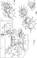
- FIG. 1shows the device with two different receiving frames with assigned different vessel carriers, namely a plate and a rack.
- the individual framesare shown separately from each other.
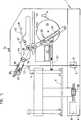
- 2shows the receiving frame for a turntable placed thereon in the state connected to the device frame.
- 3shows a side view of the connecting links in the separated state of the two frames.
- 4shows the two racks in vertical section in the coupled state, the receiving frame showing a vessel carrier designed as a rack for the sample vessels, the stopper removal device being in the piercing position of the mandrel.
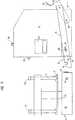
- 5shows a vertical section similar to FIG. 4, but after the plug has been pulled out of the sample vessel, and for a vessel carrier formed by a turntable.
- Figure 6is a vertical section similar to Figure 5, but in the position shortly after the plug has been removed from the mandrel.
- a frame 1carries the stopper removal device, which is essentially enclosed by a housing 2.
- the front side 3 of the frame 1is connected to a further frame 4 by means of connecting links 5 can be coupled in such a way that the two frames 1, 4 rest against each other without a gap (Fig. 2).
- different vessel carriers 6are to be used for the sample vessels 7 formed by cylindrical glass tubes
- different frames 4are provided, corresponding to the different types of vessel carriers 6, of which only two types are shown in FIG. 1 for simplicity, namely on the one hand a turntable 8 and on the other hand a rack 9.
- Each of these frames 4also has a housing 10 enclosing its components.
- the connecting links 5have a quick-release fastener, which has two brackets 11, which are guided laterally on the housing 2 of the frame 1 (FIG. 3) and are designed with hooks 12 at their ends facing the frame 4, the hook openings 13 of which are directed upwards. Bolts 14 projecting laterally from the housing 10 of the frame 4 can snap into these openings 13. Furthermore, the connecting members 5 have an electrical coupling 17 in the form of a plug-in connection, with which the electrical system of the plug removal device accommodated in the frame 1 can be connected to a separate electric motor 18 (FIGS. 4 to 6) provided in the frame 4 for the vessel carrier 6.
- brackets 11are provided with elongated holes 16, in which pins 15 arranged on the side surfaces of the housing 2 slide, about which the brackets 11 can be pivoted.
- Each bracket 11is articulated at its end facing away from the opening 13 to a link 19 which is pivotably mounted on the housing 2 at 20.
- the two side links 19are connected to each other on the back of the housing 2 and provided with a handle 21 to facilitate operation.
- the handlebars 19 together with the brackets 11form a toggle-type clamping connection which, after the bolts 14 have been hung into the openings 13 when the handle 21 is pressed down, brings the two mutually facing surfaces of the two frames 1, 4 or their housing into tight contact with one another and so the plug connection of the coupling 17 secures in the inserted position as soon as the handle 21 has been depressed in the direction of the arrow 22 (FIG. 2).
- the handle 21is swiveled up in the direction of the arrow 23 (FIG.
- Each frame 4 or its housing 10has a receptacle 24 adapted to the respective vessel carrier 6 and the motor 18 transports the vessel carrier 6 guided in the receptacle 24 step by step, so that the sample vessels 7 carried by the vessel carrier 6 in turn from their closures 40, in particular Plug closures, can be exempted (Fig. 4 to 6).
- the step-by-step movementcan easily be achieved by appropriate control of the electric motor, only the achievement of the desired position having to be ensured by suitable means.
- a stepping mechanism 25FIG. 4 engaging in the receptacle 24 is required.
- the plug removal device accommodated in the housing 2 of the frame 1has an electric motor (not shown) which is fed by the electrical system of the plug removal device carried by the frame 1 and at the same time forms the drive for a drive and control disk 26 which carries an eccentric pin 27 which is in a longitudinal slot 28 of a pivot lever 29 slides, which is pivotally mounted at 30 in the frame 1. At its free end, this pivot lever 29 is forked and drives a pin 31 of a slide 32 which is slidably mounted in a horizontal guide 33.
- the slider 32carries an upward-facing extension 34 to which a rod 35 is articulated, which is guided approximately in the middle of its length by means of a guide roller 36 on a link 37.
- the rod 35can thus be moved back and forth in the horizontal direction and its front end can be pushed out of the housing 2 through an opening 59 (FIG. 1, 2).
- This endcarries a mandrel 38 which is surrounded by a fork of a wiper 39 which slides onto the cover surface of the sealing plug 40 during the advancing movement of the rod 35.
- the stripper 39is provided with a bevel 41 on its front edge. This ensures in a simple manner that the mandrel 38 always hits the sealing plug 40 during the advancing movement of the rod 35, specifically from the side of the frame. This position is shown in Fig.4.
- a collecting funnel 46 'which leads to a discharge chute 47, which is led out of the housing 2 and outside of the housing 4 carries a collecting bag 48 attached to it, preferably a garbage bag with a cord, for receiving the collected closing plug 40 .
- a sloping section 49is provided, by means of which the rod 35 is pressed back into the horizontal position, the locking means 43, for example a ball catch, being disengaged.
- the housing 2has a start button 54 in the form of a illuminated pushbutton on its top wall.
- the described module-like design of the different frames 4 for the different vessel carriers 6includes for all frames 4 the same design of the bolts 14 and the same arrangement of the electrical coupling 17.
- the electrical connectioncan easily be adapted to the respective type of vessel carrier.
- the step switch 25which provides for a movement of the rack 9 (FIG. 1) in the direction of the arrow 55, can of course, with appropriate adaptation, also serve for the gradual movement of the turntable 8 (FIG. 1) in the direction of the arrow 56.
- a worm gear 58(FIG. 5) is provided for this.
- the deviceIn order to absorb the tilting moment which arises when the mandrel 38 is inserted into the sealing plug 40 and thus prevent the sample vessel 7 from being inclined, the device has a spring-loaded pressure pin 57 (FIG. 4) which rests in the lower section of the sample vessel 7 comes and holds the tube in place throughout the stopper removal process.
Landscapes
- Health & Medical Sciences (AREA)
- Chemical & Material Sciences (AREA)
- Clinical Laboratory Science (AREA)
- Chemical Kinetics & Catalysis (AREA)
- Engineering & Computer Science (AREA)
- Mechanical Engineering (AREA)
- Analytical Chemistry (AREA)
- General Health & Medical Sciences (AREA)
- Hematology (AREA)
- Automatic Analysis And Handling Materials Therefor (AREA)
- Sampling And Sample Adjustment (AREA)
Abstract
Description
Translated fromGermanDie Erfindung bezieht sich auf eine Vorrichtung zur automatischen Entfernung des Verschlusses von Gefäßen, die zu mehreren in Gefäßträgern angeordnet und nacheinander dem Gestell der Vorrichtung zugeführt werden, insbesondere des Stopfenverschlusses von Probengefäßen für medizinische oder technische Tests, bei welcher ein den Verschluß ergreifender Bauteil auf den Verschluß zu bewegt und der Verschluß anschließend mit diesem Bauteil vom Gefäß gelöst wird, wobei unter diesem Bauteil eine Aufnahme für den Gefäßträger angeordnet ist, für dessen schrittweise Bewegung ein Antrieb vorgesehen ist.The invention relates to a device for the automatic removal of the closure of vessels, which are arranged in groups in vessel carriers and successively fed to the frame of the device, in particular the stopper closure of sample vessels for medical or technical tests, in which a component engaging the closure on the Closure is moved and the closure is then released from the vessel with this component, a receptacle for the vessel carrier being arranged under this component, a drive being provided for the gradual movement thereof.
Auf zahlreichen Gebieten werden Proben in großer Anzahl für Untersuchungen verwendet, wobei sich jede Probe in einem unten geschlossenen und oben durch einen abnehmbaren Verschluß verschlossenen Glasröhrchen befindet. Beispiele für solche Anwendungsgebiete sind Reihenuntersuchungen von Materialien aller Art, vor allem aber medizinische bzw. klinische Labortests. In der Regel ist hiebei der Verschluß ein in das obere, offene Ende des Glasröhrchens eingedrückter Stopfenverschluß, zumeist aus Gummi, Kunststoff oder Kork. Die bei Reihenuntersuchungen geforderten hohen Leistungen lassen eine händische Entfernung des Verschlusses nicht zu, zumal bei händischer Betätigung stets die Gefahr besteht, daß das Röhrchen zu Bruch geht oder daß bei unachtsamer Öffnung des Probengefäßes zumindest ein Teil seines Inhaltes verschüttet wird, was bei aggressiven, toxischen oder mit Keimen behafteten Proben bedenklich ist. Es wurde daher bereits eine Vorrichtung der eingangs geschilderten Art zur automatischen Entfernung des Verschlußstopfens von Glasprobenröhrchen vorgeschlagen, bei welcher die Röhrchen gruppenweise in Gefäßträgern der Vorrichtung zugeführt werden. Diese Gefäßträger sind zumeist tellerartig oder rackartig ausgebildet, jedoch sind auch Sonderformen in Gebrauch. Diese Gefäßträger werden in die Vorrichtung eingesetzt und an den Bauteilen, welche den Verschlußstopfen entfernen, schrittweise vorbeigeführt, wobei ein Probengefäß nach dem anderen vom Verschlußstopfen befreit wird. Die Entfernung des Verschlußstopfens geschieht hiebei durch einen in den Stopfen einstechenden Dorn, welcher nach dem Einstechen den Verschlußstopfen aus dem Röhrchen herauszieht, worauf der Stopfen vom Dorn abgestreift und durch ein Rohr von der Vorrichtung abgeführt wird. Sind alle Probengefäße eines Gefäßträgers von den Verschlußstopfen befreit, so wird der bisher in der Vorrichtung befindliche Gefäßträger gegen einen nächsten gleichartigen Gefäßträger ausgetauscht und die Vorrichtung kann erneut mit ihrer Arbeit beginnen. Nachteilig ist an der bekannten Vorrichtung jedoch, daß sie nur für eine einzige Gefäßträgertype anwendbar ist. Befinden sich die Probengefäße in einer von der zur Vorrichtung zugehörigen Gefäßträgertype abweichenden Type des Gefäßträgers, so ist die Vorrichtung für diese neue Type unverwendbar, es muß dann eine zur neuen Gefäßträgertype passende Vorrichtung verwendet werden. In der Praxis ist es aber oft nicht vorhersehbar bzw. bestimmbar, auf welcher Type von Gefäßträgern die Probengefäße angeliefert werden, so daß in der Praxis häufig mehrere Vorrichtungen kurz hintereinander benötigt werden, entsprechend den angelieferten Gefäßträgertypen. Dies bedingt nicht nur einen erhöhten Aufwand an Vorrichtungen, sondern auch einen erhöhten Platzbedarf, dem nicht immer und überall Rechnung getragen werden kann.In numerous fields, samples are used in large numbers for examinations, each sample being in a glass tube which is closed at the bottom and sealed by a removable closure at the top. Examples of such fields of application are serial examinations of materials of all kinds, but above all medical or clinical laboratory tests. As a rule, the closure is a plug closure which is pressed into the upper, open end of the glass tube, usually made of rubber, plastic or cork. The high performance required for serial examinations does not allow the cap to be removed by hand, especially since there is always a risk that the tube will break or that at least part of its contents will be spilled if the sample vessel is opened carelessly, which is the case with aggressive, toxic substances or specimens containing germs are questionable. A device of the type described at the outset for automatically removing the sealing plug from glass sample tubes has therefore already been proposed, in which the tubes are supplied to the device in groups in vessel carriers. These vessel carriers are usually plate-like or rack-like, but special shapes are also used. These vessel carriers are inserted into the device and are gradually guided past the components which remove the stopper, one sample after the other being freed from the stopper. The plug is removed by means of a mandrel that pierces the plug, which, after being inserted, pulls the plug out of the tube, whereupon the plug is stripped from the mandrel and removed from the device through a tube. If all the sample vessels of a vessel carrier have been freed from the sealing plugs, the vessel carrier previously located in the device becomes exchanged for a next similar vessel carrier and the device can start its work again. A disadvantage of the known device, however, is that it can only be used for a single type of vessel carrier. If the sample vessels are in a type of vessel carrier that differs from the type of vessel carrier associated with the device, the device cannot be used for this new type, and a device that matches the new vessel carrier type must then be used. In practice, however, it is often not predictable or determinable on which type of vessel carrier the sample vessels are delivered, so that in practice several devices are often required in quick succession, depending on the type of vessel carrier supplied. This requires not only an increased expenditure on devices, but also an increased space requirement, which cannot always and everywhere be taken into account.
Die Erfindung setzt sich zur Aufgabe, diese Nachteile zu vermeiden und eine Vorrichtung der eingangs geschilderten Art universeller verwendbar zu machen, sodaß ein und dieselbe Vorrichtung für die Bearbeitung an unterschiedlichen Gefäßträgertypen gehaltener Probengefäße ververwendbar wird. Die Erfindung löst diese Aufgabe dadurch, daß die Aufnahme an einem vom Gestell der Vorrichtung trennbaren, gesonderten Gestell angeordnet ist, das einen eigenen Elektromotor zur Bewegung des Gefäßträgers aufweist, wobei die beiden Gestelle mittels Verbindungsgliedern miteinander koppelbar sind und diese Verbindungsglieder eine elektrische Koppelung des Elektromotors für den Gefäßträger mit dem im Gestell der Vorrichtung vorgesehenen elektrischen System beinhalten und daß für unterschiedliche Gefäßträger unterschiedliche Aufnahmen an eigenen Gestellen vorgesehen sind, die wahlweise an die Verbindungsglieder bzw. die elektrische Koppelung anschließbar sind. Dadurch reduziert sich der Aufwand für die Behandlung unterschiedlicher Gefäßträgertypen auf die unterschiedlichen Aufnahmen bzw. deren Gestelle, was gegenüber der eingangs beschriebenen Vorrichtung eine wesentliche Ersparnis darstellt. Der Wechsel von einer Aufnahmetype auf eine andere Aufnahmetype und somit von einer Gefäßträgertype auf eine andere ist rasch durchführbar und der eigene Motor für die Bewegung des jeweiligen Gefäßträgers macht komplizierte kinetische Übertragungsglieder zwischen den beiden Gestellen unnötig. Die Verbindung zwischen den beiden Gestellen reduziert sich daher auf die Verbindungsglieder, welche die beiden Gestelle aneinander derart festhalten, daß eine Relativverschiebung im Betrieb nicht möglich ist, sowie auf die elektrische Verbindung, welche einerseits zur Stromversorgung des Elektromotors des Aufnahmegestelles dient, anderseits zur Steuerung dieses Elektromotors vom Hauptgerät aus entsprechend der Funktion der den Verschluß entfernenden Bauteile.The object of the invention is to avoid these disadvantages and to make a device of the type described at the outset more universally usable, so that one and the same device can be used for processing sample vessels held on different types of vessel carrier. The invention solves this problem in that the receptacle is arranged on a separate frame which can be separated from the frame of the device and which has its own electric motor for moving the vessel carrier, the two frames being able to be coupled to one another by means of connecting elements and these connecting elements electrically coupling the electric motor for the vascular support with the electrical system provided in the frame of the device and that different receptacles are provided on separate frames for different vascular supports, which can optionally be connected to the connecting links or the electrical coupling. As a result, the outlay for the treatment of different types of vessel carriers is reduced to the different receptacles or their frames, which represents a substantial saving compared to the device described at the beginning. The change from one type of recording to another type of recording and thus from one type of carrier to another can be carried out quickly and the own motor for the movement of the respective carrier makes complicated kinetic transmission elements between the two frames unnecessary. The connection between the two frames is therefore reduced to the connecting links which hold the two frames to one another in such a way that a relative shift is not possible during operation, and to the electrical connection, which on the one hand serves to power the electric motor of the mounting frame, on the other hand to control this electric motor from the main unit according to the function of the components removing the closure.
Gemäß einer besonders einfachen Ausführungsform der Erfindung weisen die Verbindungsglieder Haken am Gestell der Vorrichtung auf, in welche Bolzen des Gestelles der Aufnahme einhängbar sind, wobei vorzugsweise die Hakenöffnungen nach oben gerichtet sind. Eine solche Verbindung erfordert nur einen geringen Aufwand und ist funktionssicher. Gemäß einer Weiterbildung hievon sind die Haken an am Gestell der Vorrichtung schwenkbar geführten seitlichen Bügeln angeordnet, welche einen Schnellverschluß bilden. Erfindungsgemäß ist ferner zweckmäßig die elektrische Koppelung von einer Steckverbindung gebildet, die in der Regel als Mehrfachstecker ausgebildet ist. Hiebei ergibt sich eine besonders günstige Ausführungsform dadurch, daß die Steckverbindung an den einander zugewandten Seiten der beiden Gestelle vorgesehen ist und durch beiderseits seitlich angeordnete kniehebelartig ausgebildete Schnellverschlüsse in der Verbindungslage gesichert ist. Dies ergibt eine Verriegelung der beiden Gestelle aneinander, welche sowohl in Einsteckrichtung der Steckverbindung gesichert ist als auch quer dazu.According to a particularly simple embodiment of the invention, the connecting links have hooks on the frame of the device, into which bolts of the frame of the receptacle can be hung, the hook openings preferably being directed upwards. Such a connection requires little effort and is reliable. According to a development thereof, the hooks are arranged on lateral brackets which are pivotably guided on the frame of the device and which form a quick-release fastener. According to the invention, the electrical coupling is also expediently formed by a plug connection, which is generally designed as a multiple plug. A particularly favorable embodiment results from the fact that the plug-in connection is provided on the mutually facing sides of the two frames and is secured in the connection position by means of quick-release fasteners arranged on both sides. This results in a locking of the two frames to one another, which is secured both in the insertion direction of the plug connection and transversely thereto.
In der Zeichnung ist ein Ausführungsbeispiel der Erfindung schematisch dargestellt. Fig.1 zeigt die Vorrichtung mit zwei unterschiedlichen AufnahmeGestellen mit zugeordneten unterschiedlichen Gefäßträgern, nämlich einem Teller und einem Rack. Die einzelnen Gestelle sind hiebei getrennt voneinander dargestellt. Fig.2 zeigt das Aufnahmegestell für einen darauf aufgesetzten Drehteller im an das Vorrichtungsgestell angeschlossenen Zustand. Fig.3 zeigt in Seitenansicht die Verbindungsglieder im getrennten Zustand der beiden Gestelle. Fig.4 zeigt die beiden Gestelle im Vertikalschnitt im aneinander angekoppelten Zustand, wobei das Aufnahmegestell einen als Rack ausgebildeten Gefäßträger für die Probengefäße zeigt, wobei die Stopfenentfernungsvorrichtung in der Einstechstellung des Dornes ist. Fig.5 zeigt einen Vertikalschnitt ähnlich Fig.4, jedoch nach der Herausziehung des Stopfens aus dem Probengefäß, und für einen von einem Drehteller gebildeten Gefäßträger. Fig.6 ist ein Vertikalschnitt ähnlich Fig.5, jedoch in der Stellung kurz nach dem Abziehen des Stopfens vom Dorn.In the drawing, an embodiment of the invention is shown schematically. 1 shows the device with two different receiving frames with assigned different vessel carriers, namely a plate and a rack. The individual frames are shown separately from each other. 2 shows the receiving frame for a turntable placed thereon in the state connected to the device frame. 3 shows a side view of the connecting links in the separated state of the two frames. 4 shows the two racks in vertical section in the coupled state, the receiving frame showing a vessel carrier designed as a rack for the sample vessels, the stopper removal device being in the piercing position of the mandrel. 5 shows a vertical section similar to FIG. 4, but after the plug has been pulled out of the sample vessel, and for a vessel carrier formed by a turntable. Figure 6 is a vertical section similar to Figure 5, but in the position shortly after the plug has been removed from the mandrel.
Ein Gestell 1 trägt die Stopfenentfernungsvorrichtung, die im wesentlichen von einem Gehäuse 2 umschlossen ist. Die Frontseite 3 des Gestelles 1 ist mit einem weiteren Gestell 4 mittels Verbindungsgliedern 5 kuppelbar, derart, daß beide Gestelle 1,4 aneinander spaltlos anliegen (Fig.2). Da unterschiedliche Gefäßträger 6 für die von zylindrischen Glasröhrchen gebildeten Probengefäße 7 zur Anwendung kommen sollen, sind unterschiedliche Gestelle 4 vorgesehen, entsprechend den verschiedenen Typen der Gefäßträger 6, von denen in Fig.1 der Einfachheit halber nur zwei Typen dargestellt sind, nämlich einerseits ein Drehteller 8 und anderseits ein Rack 9. Jedes dieser Gestelle 4 hat ebenfalls ein seine Bauteile umschließendes Gehäuse 10.A frame 1 carries the stopper removal device, which is essentially enclosed by a
Die Verbindungsglieder 5 weisen einen Schnellverschluß auf, welcher zwei seitlich am Gehäuse 2 des Gestelles 1 geführte Bügel 11 aufweist (Fig.3), die an ihren dem Gestell 4 zugewendeten Enden mit Haken 12 ausgebildet sind, deren Hakenöffnungen 13 nach oben gerichtet sind. In diese Öffnungen 13 können seitlich vom Gehäuse 10 des Gestelles 4 abstehende Bolzen 14 einrasten. Ferner weisen die Verbindungsglieder 5 eine elektrische Koppelung 17 in Form einer Steckverbindung auf, mit welcher das elektrische System der im Gestell 1 untergebrachten Stopfenentfernungsvorrichtung mit einem im Gestell 4 für den Gefäßträger 6 vorgesehenen eigenen Elektromotor 18 (Fig.4 bis 6) verbindbar ist. Zur Sicherung dieser Steckverbindung und zur Erleichterung des Einrastens der Bolzen 14 in die Öffnungen 13 sind die Bügel 11 mit Langlöchern 16 versehen, in denen an den Seitenflächen des Gehäuses 2 angeordnete Zapfen 15 gleiten, um welche die Bügel 11 schwenkbar sind. Jeder Bügel 11 ist an seinem der Öffnung 13 abgewendeten Ende an einem Lenker 19 angelenkt, der am Gehäuse 2 bei 20 schwenkbar gelagert ist. Die beiden seitlichen Lenker 19 sind an der Rückseite des Gehäuses 2 miteinander verbunden und mit einem Handgriff 21 zur Erleichterung der Betätigung versehen. Die Lenker 19 bilden zusammen mit den Bügeln 11 eine kniehebelartige Spannverbindung, welche nach Einhängen der Bolzen 14 in die Öffnungen 13 bei Niederdrücken des Handgriffes 21 die beiden einander zugewendeten Flächen der beiden Gestelle 1,4 bzw. deren Gehäuse in dichte Anlage aneinander bringt und derart die Steckverbindung der Koppelung 17 in der eingesteckten Lage sichert, sobald der Handgriff 21 in Richtung des Pfeiles 22 (Fig.2) niedergedrückt wurde. Bei Hochschwenkung des Handgriffes 21 in Richtung des Pfeiles 23 (Fig.1) wird diese Spannverbindung rasch gelöst, so daß die Stecker der Steckverbindung 17 aus den zugehörigen Buchsen herausgezogen werden, worauf die Bolzen 14 aus den Öffnungen 13 ausgehoben werden können, so daß das Gestell 4 vom Gestell 1 getrennt wird und gegen ein anderes Gestell 4 ausgetauscht werden kann. Dadurch ist ein problemloser Übergang von einer Gefäßträgertype auf eine andere Type möglich.The connecting
Jedes Gestell 4 bzw. sein Gehäuse 10 hat eine dem jeweiligen Gefäßträger 6 angepaßte Aufnahme 24 und der Motor 18 transportiert den in der Aufnahme 24 geführten Gefäßträger 6 schrittweise, so daß die vom Gefäßträger 6 getragenen Probengefäße 7 der Reihe nach von ihren Verschlüssen 40, insbesondere Stopfenverschlüssen, befreit werden können (Fig.4 bis 6). Bei als Drehteller 8 ausgebildeten Gefäßträgern 6 ist die schrittweise Bewegung leicht durch eine entsprechende Ansteuerung des Elektromotors erreichbar, wobei lediglich die Erreichung der gewünschten Position durch geeignete Mittel gesichert werden muß. Bei als Rack 9 ausgebildeten Gefäßträgern 6 (Fig.4) ist ein in die Aufnahme 24 eingreifendes Schrittschaltwerk 25 (Fig.4) erforderlich.Each
Die im Gehäuse 2 des Gestelles 1 untergebrachte Stopfenentfernungsvorrichtung hat einen nicht dargestellten Elektromotor, der vom elektrischen System der vom Gestell 1 getragenen Stopfenentfernungsvorrichtung gespeist wird und zugleich den Antrieb für eine Antriebs- und Steuerscheibe 26 bildet, die einen Exzenterzapfen 27 trägt, der in einem Längsschlitz 28 eines Schwenkhebels 29 gleitet, der bei 30 im Gestell 1 schwenkbar gelagert ist. An seinem freien Ende ist dieser Schwenkhebel 29 gegabelt ausgebildet und treibt einen Zapfen 31 eines Gleitstückes 32, das in einer horizontalen Führung 33 verschiebbar gelagert ist. Das Gleitstück 32 trägt einen nach oben weisenden Fortsatz 34, an welchem eine Stange 35 angelenkt ist, die etwa in der Mitte ihrer Länge mittels einer Führungsrolle 36 an einer Kulisse 37 geführt ist. Die Stange 35 ist somit in horizontaler Richtung hin und her verschiebbar und kann mit ihrem vorderen Ende durch eine Öffnung 59 (Fig.1,2) aus dem Gehäuse 2 herausgeschoben werden. Dieses Ende trägt einen Dorn 38, der von einer Gabel eines Abstreifers 39 umgeben ist, der bei der Vorschubbewegung der Stange 35 auf die Deckfläche des Verschlußstopfens 40 aufgleitet. Um dies auch für unterschiedliche Höhen der Glasröhrchen (Probengefäße 7) zu ermöglichen, ist der Abstreifer 39 an seiner Vorderkante mit einer Abschrägung 41 versehen. Dadurch wird auf einfache Weise gesichert, daß der Dorn 38 bei der Vorschubbewegung der Stange 35 stets auf den Verschlußstopfen 40 trifft, und zwar von der Seite des Gestelles her. Diese Stellung ist in Fig.4 dargestellt. Im Anschluß an das Erreichen dieser Stellung gleitet die Führungsrolle 36 an einem ansteigenden Abschnitt 42 der Kulisse 37 hoch, wodurch der Stopfen 40 aus dem Probengefäß 7 herausgezogen wird (Fig.5). In dieser hochgeschwenkten Stellung der Stange 35 rastet eine Arretierung 43 an der Schwenklagerung der Stange 35 am Fortsatz 34 ein und hält dadurch die Stange 35 in der hochgeschwenkten Stellung, solange die Führungsrolle 36 entlang eines horizontalen Abschnittes 44 der Kulisse gleitet, wobei die Stange 35 samt dem Dorn 38 und dem daran haftenden Verschlußstopfen 40 in das Innere des Gehäuses 2 zurückgezogen wird. Bei Erreichen des Endes dieses Abschnittes 44 kommt ein Anschlag 45 zur Anlage an das Hinterende des Abstreifers 39 (Fig.6), wodurch dieser entgegen der Wirkung einer Feder 46 (Fig.4) relativ zur Stange 35 gegen die Spitze des Dornes 38 zu bewegt wird und dadurch den Verschlußstopfen 40 vom Dorn 38 abzieht. Der gelöste Verschlußstopfen 40 fällt in einen Auffangtrichter 46′, welcher zu einem Abfuhrschacht 47 führt, der aus dem Gehäuse 2 herausgeführt ist und außerhalb des Gehäuses 4 einen an ihm befestigten Sammelbeutel 48, vorzugsweise einen Müllbeutel mit Schnurzug, zur Aufnahme der gesammelten Verschlußstopfen 40 trägt. Im Anschluß an den horizontalen Abschnitt 44 der Kulisse 37 ist ein abfallender Abschnitt 49 vorgesehen, durch welchen die Stange 35 wieder in die horizontale Position zurückgedrückt wird, wobei die Arretierung 43, z.B. eine Kugelrast, ausgerückt wird. Nach Erreichung der hinteren Totpunktlage der Stange 35 beginnt deren Vorschubbewegung aufs Neue und die Vorgänge wiederholen sich, solange sich die Scheibe 26 in Richtung des Pfeiles 50 dreht. Dies ist der Fall, solange nicht ein Stoppschalter 51 (Fig.4) die Drehung der Scheibe 26 unterbricht, wobei die Scheibe 26 durch Einrasten des Schalters 51 in eine Rast 52 am Umfang der Scheibe 26 blockiert wird. Dies ist der Fall, sobald ein Sensor 53, zweckmäßig ein Infrarotsensor, welcher an der Frontseite 3 des Gehäuses 2 angeordnet ist, feststellt, daß sich vor jener Öffnung 59 der Frontseite 3, durch welche die Stange 35 mit dem Dorn 38 austritt, kein Probengefäß 7 oder ein Probengefäß 7 ohne Verschlußstopfen 40 befindet.The plug removal device accommodated in the
Das Gehäuse 2 trägt an seiner Deckwand eine als Leuchtdrucktaste ausgebildete Starttaste 54.The
Die beschriebene modulartige Ausbildung der unterschiedlichen Gestelle 4 für die unterschiedlichen Gefäßträger 6 beinhaltet für alle Gestelle 4 eine gleiche Ausbildung der Bolzen 14 und eine gleiche Anordnung der elektrischen Koppelung 17. Durch unterschiedliche Stecker dieser Koppelung 17, welche in die ihnen zugeordneten Buchsen des Gestelles 1 eingeführt werden, läßt sich jedoch die elektrische Verbindung leicht an die jeweils vorliegende Gefäßträgertype anpassen.The described module-like design of the
Der für eine Bewegung des Racks 9 (Fig.1) in Richtung des Pfeiles 55 sorgende Schrittschalter 25 (Fig.4) kann selbstverständlich mit entsprechender Anpassung auch zur schrittweisen Bewegung des Drehtellers 8 (Fig.1) in Richtung des Pfeiles 56 dienen. Üblicherweise ist jedoch hiefür ein Schneckengetriebe 58 (Fig.5) vorgesehen.The step switch 25 (FIG. 4), which provides for a movement of the rack 9 (FIG. 1) in the direction of the
Um das beim Einstechen des Dornes 38 in den Verschlußstopfen 40 entstehende Kippmoment auf das Probengefäß 7 aufzunehmen und damit eine Schrägstellung des Probengefäßes 7 zu verhindern, hat die Vorrichtung einen gefederten Andruckbolzen 57 (Fig.4), der im unteren Abschnitt des Probengefäßes 7 zur Anlage kommt und das Röhrchen während des gesamten Stopfenentfernungsprozesses festhält.In order to absorb the tilting moment which arises when the
Wenngleich die beschriebene Vorrichtung für die Verwendung bei einem Stopfenverschluß eines Probengefäßes näher beschrieben wurde, so versteht es sich, daß diese Vorrichtung mit gleichen Vorteilen auch für andersgeartete Ge fäßverschlüsse anwendbar ist, da es in erster Linie auf die auswechselbare Gestaltung der Aufnahmen für unterschiedliche Gefäßträgertypen ankommt, wobei alle, die unterschiedlichen Gefäßträgertypen 6 tragenden Gestelle 1 in gleicher Weise an das stets verwendete Grundgestell 1 der Vorrichtung andockbar sind.Although the device described for use in a stopper closure of a sample vessel has been described in more detail, it goes without saying that this device can also be used for other types of vessel closures with the same advantages, since it primarily depends on the interchangeable design of the receptacles for different types of vessel carriers , whereby all the racks 1 carrying the different types of
Claims (6)
Translated fromGermanApplications Claiming Priority (2)
| Application Number | Priority Date | Filing Date | Title |
|---|---|---|---|
| AT2354/90 | 1990-11-20 | ||
| AT235490AAT397240B (en) | 1990-11-20 | 1990-11-20 | DEVICE FOR AUTOMATICALLY REMOVING THE SEALING OF VESSELS |
Publications (2)
| Publication Number | Publication Date |
|---|---|
| EP0487492A1true EP0487492A1 (en) | 1992-05-27 |
| EP0487492B1 EP0487492B1 (en) | 1994-03-02 |
Family
ID=3532799
Family Applications (1)
| Application Number | Title | Priority Date | Filing Date |
|---|---|---|---|
| EP19910890277Expired - LifetimeEP0487492B1 (en) | 1990-11-20 | 1991-11-13 | Device for automatically removing stoppers from containers |
Country Status (3)
| Country | Link |
|---|---|
| EP (1) | EP0487492B1 (en) |
| AT (1) | AT397240B (en) |
| DE (1) | DE59101096D1 (en) |
Cited By (7)
| Publication number | Priority date | Publication date | Assignee | Title |
|---|---|---|---|---|
| EP0676643A3 (en)* | 1994-04-09 | 1996-02-28 | Boehringer Mannheim Gmbh | System for contamination-free reaction processes. |
| WO1998001760A3 (en)* | 1996-07-05 | 1998-06-11 | Beckman Instruments Inc | Automated sample processing system |
| WO2002078431A3 (en)* | 2001-03-29 | 2003-03-20 | Hauptner Und Richard Herberhol | Animal ear tag pliers |
| ES2239871A1 (en)* | 2003-01-30 | 2005-10-01 | Jesus Hector Miñano Ocaña | Linear, horizontal and decrowner staggered machine for tube during clinical analyses, has movable support provided with top frontal, where tilt is generated by gear motor and small spindle such that comb is tilted |
| WO2006003221A1 (en)* | 2004-06-28 | 2006-01-12 | Minano Ocana Jesus Hector | Horizontal, stepped, linear machine for removing caps from tubes for clinical analyses |
| WO2021086910A1 (en) | 2019-10-29 | 2021-05-06 | Beckman Coulter, Inc. | Sample tube decapper |
| CN113968562A (en)* | 2021-11-03 | 2022-01-25 | 江苏医药职业学院 | Medical science inspection laboratory is with instrument of opening tub |
Citations (2)
| Publication number | Priority date | Publication date | Assignee | Title |
|---|---|---|---|---|
| FR2013530A1 (en)* | 1968-07-23 | 1970-04-03 | Coulter Electronics | |
| DE3141780A1 (en)* | 1981-10-21 | 1983-05-11 | BNA-Augustin GmbH & CO KG, 7631 Kappel | Automatic device for removing rubber closure stoppers from container tubes for analytical equipment |
Family Cites Families (2)
| Publication number | Priority date | Publication date | Assignee | Title |
|---|---|---|---|---|
| US3538962A (en)* | 1968-02-01 | 1970-11-10 | Warren E Gilson | Coupled articulated containers and apparatus utilizing same |
| DE3537137A1 (en)* | 1985-10-18 | 1987-04-23 | Henkel Kgaa | CARRIER ELEMENT TO TAKE A CONTAINER |
- 1990
- 1990-11-20ATAT235490Apatent/AT397240B/ennot_activeIP Right Cessation
- 1991
- 1991-11-13EPEP19910890277patent/EP0487492B1/ennot_activeExpired - Lifetime
- 1991-11-13DEDE91890277Tpatent/DE59101096D1/ennot_activeExpired - Fee Related
Patent Citations (2)
| Publication number | Priority date | Publication date | Assignee | Title |
|---|---|---|---|---|
| FR2013530A1 (en)* | 1968-07-23 | 1970-04-03 | Coulter Electronics | |
| DE3141780A1 (en)* | 1981-10-21 | 1983-05-11 | BNA-Augustin GmbH & CO KG, 7631 Kappel | Automatic device for removing rubber closure stoppers from container tubes for analytical equipment |
Cited By (15)
| Publication number | Priority date | Publication date | Assignee | Title |
|---|---|---|---|---|
| EP0676643A3 (en)* | 1994-04-09 | 1996-02-28 | Boehringer Mannheim Gmbh | System for contamination-free reaction processes. |
| US5846489A (en)* | 1994-04-09 | 1998-12-08 | Boehringer Mannheim Gmbh | System for opening closures of vessels and for the contamination-free operation of reaction sequences |
| WO1998001760A3 (en)* | 1996-07-05 | 1998-06-11 | Beckman Instruments Inc | Automated sample processing system |
| US6060022A (en)* | 1996-07-05 | 2000-05-09 | Beckman Coulter, Inc. | Automated sample processing system including automatic centrifuge device |
| US8038942B2 (en) | 1996-07-05 | 2011-10-18 | Beckman Coulter, Inc. | Automated sample processing system |
| WO2002078431A3 (en)* | 2001-03-29 | 2003-03-20 | Hauptner Und Richard Herberhol | Animal ear tag pliers |
| ES2249145B1 (en)* | 2003-01-30 | 2007-05-16 | Jesus Hector Miñano Ocaña | IMPROVEMENTS INTRODUCED IN THE PATENT OF INVENTION P 200300231 BY LINEAR, SCALONED AND HORIZONTAL DETACHING MACHINE OF CLINICAL ANALYSIS PIPES. |
| ES2249145A1 (en)* | 2003-01-30 | 2006-03-16 | Jesus Hector Miñano Ocaña | Horizontal stepped linear machine for removing cap from test tube for clinical analysis, has motor reducer in base plate, to move horizontal plate such that plate penetrates between tube and cap when cap is separated |
| ES2239871B1 (en)* | 2003-01-30 | 2006-11-01 | Jesus Hector Miñano Ocaña | LINEAR, SCALONED AND HORIZONTAL DETAPONING MACHINE OF CLINICAL ANALYSIS TUBES. |
| ES2239871A1 (en)* | 2003-01-30 | 2005-10-01 | Jesus Hector Miñano Ocaña | Linear, horizontal and decrowner staggered machine for tube during clinical analyses, has movable support provided with top frontal, where tilt is generated by gear motor and small spindle such that comb is tilted |
| WO2006003221A1 (en)* | 2004-06-28 | 2006-01-12 | Minano Ocana Jesus Hector | Horizontal, stepped, linear machine for removing caps from tubes for clinical analyses |
| WO2021086910A1 (en) | 2019-10-29 | 2021-05-06 | Beckman Coulter, Inc. | Sample tube decapper |
| CN114616205A (en)* | 2019-10-29 | 2022-06-10 | 贝克曼库尔特有限公司 | Sample tube decapper |
| EP4051622A4 (en)* | 2019-10-29 | 2023-12-13 | Beckman Coulter, Inc. | SAMPLE TUBE CAPPLOVER |
| CN113968562A (en)* | 2021-11-03 | 2022-01-25 | 江苏医药职业学院 | Medical science inspection laboratory is with instrument of opening tub |
Also Published As
| Publication number | Publication date |
|---|---|
| DE59101096D1 (en) | 1994-04-07 |
| AT397240B (en) | 1994-02-25 |
| EP0487492B1 (en) | 1994-03-02 |
| ATA235490A (en) | 1993-07-15 |
Similar Documents
| Publication | Publication Date | Title |
|---|---|---|
| DE60119629T2 (en) | Apparatus for the treatment of blood samples | |
| DE102012213824B4 (en) | Knife holder with blade changing device | |
| DE69601693T2 (en) | Piercing and plug-setting device for a machine for dispensing dyes or similar liquid products | |
| EP2207019B1 (en) | Weighed goods holder for a weighing machine | |
| DE3515824A1 (en) | METHOD AND DEVICE FOR REMOVING LIQUID FROM A CONTAINER | |
| DE69109804T2 (en) | Device for separating the core, the skin and the flesh of a fruit, in particular a pineapple. | |
| DE2736551A1 (en) | PIPETTE | |
| DE1698268B1 (en) | METHOD AND DEVICE FOR CLEANING THE EXTRACTION TUBE OF A CONTINUOUS ANALYSIS OF LIQUID SAMPLES EQUIPMENT | |
| DE19512905A1 (en) | Device for pulling or unscrewing closures from vessels | |
| DE3734267A1 (en) | DEVICE FOR SEMI- OR FULLY AUTOMATIC CLEANING OF PAINT AND PAINT SPRAY GUNS OD. DGL. AS WELL AS COLORED AND LACQUERED OBJECTS | |
| EP0487492B1 (en) | Device for automatically removing stoppers from containers | |
| EP1048305A2 (en) | Device for transferring blood | |
| DE2725080A1 (en) | Centrifugal mixer taking various vessels sizes - having pair of plates mounted on spindle inside housing having ribs on plate, the gap between plates being adjustable | |
| DE1598220B2 (en) | Automatic pipetting device | |
| DE69002706T2 (en) | Unattended exchange of plotter pens. | |
| DE3031306A1 (en) | DEVICE FOR FILLING A LIQUID IN A FLEXIBLE, COMBINABLE CONTAINER. | |
| AT399332B (en) | DEVICE FOR AUTOMATICALLY REMOVING THE PLUG OF VESSELS | |
| DE9011116U1 (en) | Device for closing the receiving container of a blood centrifuge cell in a centrifuge machine | |
| DE3042871A1 (en) | MACHINE FOR SHAPING WORKPIECES | |
| DE3141780C2 (en) | Automatic device for removing rubber stoppers from container tubes for analysis devices | |
| DE2832166A1 (en) | METHOD AND DEVICE FOR DISTRIBUTING DISCS | |
| DE2117341B2 (en) | DEVICE FOR SUCCESSIVE FEEDING OF AN ANALYZER WITH A ROW OF SAMPLES IN SAMPLE TRAYS | |
| DE2117341C3 (en) | ||
| DE3407646A1 (en) | DEVICE FOR TAKING MATERIAL SAMPLES | |
| DE2651903A1 (en) | Automatic preparation and handling of samples for analysis - with transfer from linear to circular magazine and automatic washing |
Legal Events
| Date | Code | Title | Description |
|---|---|---|---|
| PUAI | Public reference made under article 153(3) epc to a published international application that has entered the european phase | Free format text:ORIGINAL CODE: 0009012 | |
| AK | Designated contracting states | Kind code of ref document:A1 Designated state(s):CH DE FR GB LI SE | |
| 17P | Request for examination filed | Effective date:19921002 | |
| 17Q | First examination report despatched | Effective date:19930628 | |
| GRAA | (expected) grant | Free format text:ORIGINAL CODE: 0009210 | |
| AK | Designated contracting states | Kind code of ref document:B1 Designated state(s):CH DE FR GB LI SE | |
| PG25 | Lapsed in a contracting state [announced via postgrant information from national office to epo] | Ref country code:SE Free format text:THE PATENT HAS BEEN ANNULLED BY A DECISION OF A NATIONAL AUTHORITY Effective date:19940302 Ref country code:GB Effective date:19940302 Ref country code:FR Free format text:THE PATENT HAS BEEN ANNULLED BY A DECISION OF A NATIONAL AUTHORITY Effective date:19940302 | |
| REF | Corresponds to: | Ref document number:59101096 Country of ref document:DE Date of ref document:19940407 | |
| EN | Fr: translation not filed | ||
| GBV | Gb: ep patent (uk) treated as always having been void in accordance with gb section 77(7)/1977 [no translation filed] | Effective date:19940302 | |
| PG25 | Lapsed in a contracting state [announced via postgrant information from national office to epo] | Ref country code:LI Effective date:19941130 Ref country code:CH Effective date:19941130 | |
| PLBE | No opposition filed within time limit | Free format text:ORIGINAL CODE: 0009261 | |
| STAA | Information on the status of an ep patent application or granted ep patent | Free format text:STATUS: NO OPPOSITION FILED WITHIN TIME LIMIT | |
| 26N | No opposition filed | ||
| REG | Reference to a national code | Ref country code:CH Ref legal event code:PL | |
| PGFP | Annual fee paid to national office [announced via postgrant information from national office to epo] | Ref country code:DE Payment date:19961024 Year of fee payment:6 | |
| PG25 | Lapsed in a contracting state [announced via postgrant information from national office to epo] | Ref country code:DE Free format text:LAPSE BECAUSE OF NON-PAYMENT OF DUE FEES Effective date:19980801 |