EP0486369B1 - Hydraulic anti-vibration bush - Google Patents
Hydraulic anti-vibration bushDownload PDFInfo
- Publication number
- EP0486369B1 EP0486369B1EP91402997AEP91402997AEP0486369B1EP 0486369 B1EP0486369 B1EP 0486369B1EP 91402997 AEP91402997 AEP 91402997AEP 91402997 AEP91402997 AEP 91402997AEP 0486369 B1EP0486369 B1EP 0486369B1
- Authority
- EP
- European Patent Office
- Prior art keywords
- narrow channel
- connection
- pockets
- vibration sleeve
- sleeve according
- Prior art date
- Legal status (The legal status is an assumption and is not a legal conclusion. Google has not performed a legal analysis and makes no representation as to the accuracy of the status listed.)
- Expired - Lifetime
Links
- 229920001971elastomerPolymers0.000claimsdescription11
- 239000000806elastomerSubstances0.000claimsdescription11
- 239000007788liquidSubstances0.000claimsdescription11
- 238000013016dampingMethods0.000claimsdescription6
- 230000002787reinforcementEffects0.000description9
- 230000010355oscillationEffects0.000description6
- 210000004027cellAnatomy0.000description3
- 239000012528membraneSubstances0.000description3
- 208000031968CadaverDiseases0.000description2
- 240000008042Zea maysSpecies0.000description2
- 238000005096rolling processMethods0.000description2
- 230000002528anti-freezeEffects0.000description1
- 230000005540biological transmissionEffects0.000description1
- 238000002485combustion reactionMethods0.000description1
- 239000000470constituentSubstances0.000description1
- 238000010276constructionMethods0.000description1
- 238000010586diagramMethods0.000description1
- 239000013536elastomeric materialSubstances0.000description1
- 229940082150encoreDrugs0.000description1
- 239000002184metalSubstances0.000description1
- 238000000465mouldingMethods0.000description1
Images

Classifications
- F—MECHANICAL ENGINEERING; LIGHTING; HEATING; WEAPONS; BLASTING
- F16—ENGINEERING ELEMENTS AND UNITS; GENERAL MEASURES FOR PRODUCING AND MAINTAINING EFFECTIVE FUNCTIONING OF MACHINES OR INSTALLATIONS; THERMAL INSULATION IN GENERAL
- F16F—SPRINGS; SHOCK-ABSORBERS; MEANS FOR DAMPING VIBRATION
- F16F13/00—Units comprising springs of the non-fluid type as well as vibration-dampers, shock-absorbers, or fluid springs
- F16F13/04—Units comprising springs of the non-fluid type as well as vibration-dampers, shock-absorbers, or fluid springs comprising both a plastics spring and a damper, e.g. a friction damper
- F16F13/06—Units comprising springs of the non-fluid type as well as vibration-dampers, shock-absorbers, or fluid springs comprising both a plastics spring and a damper, e.g. a friction damper the damper being a fluid damper, e.g. the plastics spring not forming a part of the wall of the fluid chamber of the damper
- F16F13/08—Units comprising springs of the non-fluid type as well as vibration-dampers, shock-absorbers, or fluid springs comprising both a plastics spring and a damper, e.g. a friction damper the damper being a fluid damper, e.g. the plastics spring not forming a part of the wall of the fluid chamber of the damper the plastics spring forming at least a part of the wall of the fluid chamber of the damper
- F16F13/14—Units of the bushing type, i.e. loaded predominantly radially
Definitions
- the inventionrelates to hydraulic antivibration sleeves comprising two rigid tubular reinforcements surrounding each other and preferably of revolution at least in part, coaxial and concentric at least under load, reinforcements joined together by an elastomer body shaped so as to form therewith at least two sealed pockets diametrically opposite in a direction D and communicating with each other by a narrow channel, all of said pockets and said channel being filled with a damping liquid.
- Such sleevesare intended to be mounted between two rigid parts which can be secured respectively to the two frames and which are liable to undergo, relative to each other, oscillations oriented in the diametrical direction D, the assembly being arranged in such a way that, for at least some of these oscillations, the liquid is discharged alternately from one of the pockets towards the other and vice versa through the narrow channel, which creates in this liquid, for a given frequency of oscillations, frequency whose value F is directly linked to the dimensions of said channel, a resonance phenomenon capable of damping the transmission of these oscillations from one of the reinforcements to the other.
- the sleeves of the type in questionare for example intended to be interposed between, on the one hand, a vehicle chassis and, on the other hand, the internal combustion engine or the front or rear axle of this vehicle.
- the inventionrelates more particularly, among the above sleeves, those in which, on the one hand, the portion of the elastomer body which delimits at least one of the pockets has in axial section the general shape of a U or V open radially outwards and is adhered against two rigid annular sections which admit the axis of the external tubular reinforcement and which are disposed respectively inside the two axial ends of this reinforcement, near these ends, at least one of these two sections containing the above narrow channel and, on the other hand, the axially central portion of the elastomer body is in the form of two arms extending radially between the two frames and parallel to the axes of these two frames.
- the ratio R between the length of the single narrow channel (or of each of its components, if this channel is split) and its width, or equivalent diameter,is relatively low, namely generally less than 100.
- the sleeves of the type in question according to the inventionare essentially characterized in that their narrow channel comprises in series two sections belonging respectively to the two annular profiles and a connector connecting these two sections together and extending axially along from the outer edge of one of the two radial arms constituting the elastomer body.
- the inventionincludes, apart from these main provisions, certain other provisions which are preferably used at the same time and which will be more explicitly discussed below.
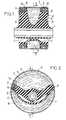
- FIGS. 1 and 2 of these drawingsshow a hydraulic anti-vibration sleeve established according to the invention, respectively in axial section according to I-I in FIG. 2 and in cross section according to II-II in FIG. 1.
- Figure 3shows in perspective view said sleeve, external tubular frame removed.
- Figure 4is a diagram showing the path followed by the narrow channel included by the above sleeve.
- the internal frame 1is intended to be secured with a pin (not shown) which passes through it contiguously while the external frame 2 is intended to be secured with a bearing (not shown), this pin and this bearing being secured respectively to two rigid elements between which it is desired to mount an anti-vibration support, elements such as a vehicle engine and the chassis of this vehicle.
- This portionalso includes two arms or radial webs 6 extending parallel to the axes of the tubular reinforcements and diametrically opposite or extending according to a widely open V as seen in Figure 2, arms which delimit with the walls 5 and the frame external 2 room A.
- the portion of the body 3 which delimits the chamber Bis constituted by a thin flexible membrane 7.
- This membraneis in the form of a curved strip in a semicircle and slightly curved towards the axis.
- This striphas two semi-circular edges connected in leaktight manner to the external frame 2 and the two ends of said strip considered in the circumferential direction are connected to the radial arms 6, a pocket C open axially in the open air being thus formed between these arms and the membrane 7.
- the portions, of the elastomer body 3, corresponding to the ends of the two arms of the U or Vare adhered against two circular sections 8, 9 having a straight U-shaped section open radially outward.
- the two channels 10 and 11are here connected in series by an intermediate connector 12, which forms a single and relatively long channel Z.
- the connector 12extends parallel to the axes of the tubular reinforcements, along the outer edge of one of the two arms or radial sails 6.
- each of the pockets A and B, inside the central portion of the outer frame 2remains free, which makes possible large radial deflections of the sleeve, for a given outer diameter thereof.
- the general construction of the sleeveis in no way complicated by the presence of said connector 12, which harmoniously completes the radial arm 6 which it borders, by being for example simply hollowed out in this edge or by constituting a lateral frame of said arm.
- the two ends of the single channel Zopen respectively into the two pockets A and B by two orifices 13, 14 made respectively in the two sections 8 and 9.
- the chambers A and B as well as the channel Z which connects themare filled with a damping liquid, generally of an antifreeze type.
- the connector 12consists of a rectilinear longitudinal bar 15 of a perforated rigid cylindrical cage composed of this bar and the two annular sections 8 and 9.
- the narrow channel Zis then formed by a series of grooves and gullies dug in the external cylindrical face of said cage and all capped in a sealed manner by the external tubular frame 2.
- the longitudinal bar 15is arranged along the outer edge of one of the two webs 6 of elastomeric material, which web is adhered to said bar.
- the mouths of the narrow channel Z in the two chambers A and Bare preferably angularly close to the bar 15, which they angularly frame, so that each section of profile 8 or 9 constituting of the Z channel extends over a neighboring arc of 360 ° around the axis of the sleeve and that the relative length of the Z channel is thus relatively high.
- This lengthcan easily be more than two times greater than the length of the usual single narrow channels.
Landscapes
- Engineering & Computer Science (AREA)
- General Engineering & Computer Science (AREA)
- Mechanical Engineering (AREA)
- Combined Devices Of Dampers And Springs (AREA)
Description
Translated fromFrenchL'invention est relative aux manchons antivibratoires hydrauliques comprenant deux armatures rigides tubulaires s'entourant l'une l'autre et de préférence de révolution au moins en partie, coaxiales et concentriques au moins sous charge, armatures réunies entre elles par un corps en élastomère conformé de façon à former avec celles-ci au moins deux poches étanches opposées diamétralement selon une direction D et communiquant entre elles par un canal étroit, l'ensemble desdites poches et dudit canal étant rempli d'un liquide amortisseur.The invention relates to hydraulic antivibration sleeves comprising two rigid tubular reinforcements surrounding each other and preferably of revolution at least in part, coaxial and concentric at least under load, reinforcements joined together by an elastomer body shaped so as to form therewith at least two sealed pockets diametrically opposite in a direction D and communicating with each other by a narrow channel, all of said pockets and said channel being filled with a damping liquid.
De tels manchons sont destinés à être montés entre deux pièces rigides solidarisables respectivement avec les deux armatures et susceptibles de subir l'une par rapport à l'autre des oscillations orientées selon la direction diamétrale D, l'ensemble étant agencé de façon telle que, pour certaines au moins de ces oscillations, le liquide soit refoulé alternativement de l'une des poches vers l'autre et inversement à travers le canal étroit, ce qui crée dans ce liquide, pour une fréquence donnée des oscillations, fréquence dont la valeur F est directement liée aux cotes dudit canal, un phénomène de résonance propre à amortir la transmission de ces oscillations de l'une des armatures à l'autre.Such sleeves are intended to be mounted between two rigid parts which can be secured respectively to the two frames and which are liable to undergo, relative to each other, oscillations oriented in the diametrical direction D, the assembly being arranged in such a way that, for at least some of these oscillations, the liquid is discharged alternately from one of the pockets towards the other and vice versa through the narrow channel, which creates in this liquid, for a given frequency of oscillations, frequency whose value F is directly linked to the dimensions of said channel, a resonance phenomenon capable of damping the transmission of these oscillations from one of the reinforcements to the other.
Les manchons du genre en question sont par exemple destinés à être interposés entre, d'une part, un châssis de véhicule et, d'autre part, le moteur à combustion interne ou le train avant ou arrière de ce véhicule.The sleeves of the type in question are for example intended to be interposed between, on the one hand, a vehicle chassis and, on the other hand, the internal combustion engine or the front or rear axle of this vehicle.
L'invention concerne plus particulièrement, parmi les manchons ci-dessus, ceux dans lesquels, d'une part, la portion du corps en élastomère qui délimite l'une au moins des poches présente en section axiale la forme générale d'un U ou V ouvert radialement vers l'extérieur et est adhérée contre deux profilés annulaires rigides qui admettent pour axe l'axe de l'armature tubulaire externe et qui sont disposés respectivement à l'intérieur des deux extrémités axiales de cette armature, à proximité de ces extrémités, l'un au moins de ces deux profilés contenant le canal étroit ci-dessus et, d'autre part, la portion axialement centrale du corps en élastomère se présente sous la forme de deux bras s'étendant radialement entre les deux armatures et parallèlement aux axes de ces deux armatures.The invention relates more particularly, among the above sleeves, those in which, on the one hand, the portion of the elastomer body which delimits at least one of the pockets has in axial section the general shape of a U or V open radially outwards and is adhered against two rigid annular sections which admit the axis of the external tubular reinforcement and which are disposed respectively inside the two axial ends of this reinforcement, near these ends, at least one of these two sections containing the above narrow channel and, on the other hand, the axially central portion of the elastomer body is in the form of two arms extending radially between the two frames and parallel to the axes of these two frames.
De tels manchons ont été décrits dans le brevet EUROPE n° 0 248 714.Such sleeves have been described in EUROPE patent No. 0 248 714.
Dans les modes de réalisation connus desdits manchons, le canal étroit est :
- soit unique et constitué par une partie au moins de l'un des deux profilés annulaires,
- soit dédoublé, c'est-à-dire composé de deux tronçons en parallèle et appartenant respectivement aux deux profilés annulaires.
- either unique and consisting of at least part of one of the two annular sections,
- is split, that is to say composed of two sections in parallel and belonging respectively to the two annular sections.
Dans ces conditions, le rapport R entre la longueur du canal étroit unique (ou de chacun de ses composants, si ce canal est dédoublé) et sa largeur, ou diamètre équivalent, est relativement faible, savoir en général inférieur à 100.Under these conditions, the ratio R between the length of the single narrow channel (or of each of its components, if this channel is split) and its width, or equivalent diameter, is relatively low, namely generally less than 100.
Pour certaines applications, on désire augmenter le rapport R tout en conservant pour le diamètre équivalent du canal étroit une valeur suffisamment élevée pour que la masse de liquide concernée par les phénomènes de résonance assurant l'amortissement demeure suffisante.For certain applications, it is desired to increase the ratio R while retaining a sufficiently high value for the equivalent diameter of the narrow channel so that the mass of liquid concerned by the resonance phenomena ensuring the damping remains sufficient.
C'est par exemple le cas lorqu'on désire assurer un amortissement efficace d'oscillations à basse fréquence telles que celles, comprises entre 5 et 20 Hz, engendrées sur un véhicule en roulement par les irrégularités de la route (hachis).This is for example the case when it is desired to provide effective damping of low frequency oscillations such as those, between 5 and 20 Hz, generated on a rolling vehicle by road irregularities (hash).
A cet effet, on profite du fait que l'on dispose dans les supports considérés de deux profilés annulaires pour les exploiter tous les deux aux fins de constitution de la "colonne liquide" exploitée pour assurer l'amortissement.To this end, it takes advantage of the fact that there are in the supports considered two annular sections to use them both for the purpose of constituting the "liquid column" used to provide depreciation.
A cet effet, les manchons du genre en question selon l'invention sont essentiellement caractérisés en ce que leur canal étroit comprend en série deux tronçons appartenant respectivement aux deux profilés annulaires et un raccord reliant entre eux ces deux tronçons et s'étendant axialement le long du bord extérieur de l'un des deux bras radiaux constitutifs du corps en élastomère.To this end, the sleeves of the type in question according to the invention are essentially characterized in that their narrow channel comprises in series two sections belonging respectively to the two annular profiles and a connector connecting these two sections together and extending axially along from the outer edge of one of the two radial arms constituting the elastomer body.
Dans des modes de réalisation avantageux, on a recours en outre à l'une et/ou à l'autre des dispositions suivantes :
- les deux profilés annulaires et le raccord forment ensemble une cage cylindrique rigide solidarisée avec l'armature tubulaire externe et dont le raccord constitue un barreau,
- la cage est constituée de deux moitiés juxtaposées axialement,
- les embouchures du canal étroit dans les deux poches sont disposées à proximité du raccord, angulairement de part et d'autre de ce raccord,
- la liaison entre le raccord et chaque tronçon annulaire est dessinée de façon à éviter tout changement brusque de direction pour l'écoulement du liquide,
- le canal étroit est constitué par un tuyau incurvé et coudé.
- the two annular sections and the connection together form a rigid cylindrical cage secured to the external tubular frame and the connection of which constitutes a bar,
- the cage consists of two axially juxtaposed halves,
- the mouths of the narrow channel in the two pockets are arranged near the fitting, angularly on either side of this fitting,
- the connection between the fitting and each annular section is designed so as to avoid any sudden change of direction for the flow of the liquid,
- the narrow channel is formed by a curved and bent pipe.
L'invention comprend, mises à part ces dispositions principales, certaines autres dispositions qui s'utilisent de préférence en même temps et dont il sera plus explicitement question ci-après.The invention includes, apart from these main provisions, certain other provisions which are preferably used at the same time and which will be more explicitly discussed below.
Dans ce qui suit, l'on va décrire un mode de réalisation de l'invention en se référant aux dessins ci-annexés d'une manière bien entendu non limitative.In the following, an embodiment of the invention will be described with reference to the drawings appended hereto of course in a nonlimiting manner.
Les figures 1 et 2, de ces dessins, montrent un manchon antivibratoire hydraulique établi selon l'invention, respectivement en coupe axiale selon I-I figure 2 et en coupe transversale selon II-II figure 1.FIGS. 1 and 2, of these drawings, show a hydraulic anti-vibration sleeve established according to the invention, respectively in axial section according to I-I in FIG. 2 and in cross section according to II-II in FIG. 1.
La figure 3 montre en vue perspective ledit manchon, armature tubulaire externe enlevée.Figure 3 shows in perspective view said sleeve, external tubular frame removed.
La figure 4 est un schéma montrant le trajet suivi par le canal étroit compris par le manchon ci-dessus.Figure 4 is a diagram showing the path followed by the narrow channel included by the above sleeve.
Le manchon en question comprend :
- une armature métallique tubulaire interne de révolution 1,
- une armature métallique tubulaire externe de
révolution 2 qui entoure l'armature 1 et qui, pour l'état monté et chargé du manchon, peut être coaxiale à cette armature 1, les axes des deux armatures étant de toute façon parallèles entre eux au repos du manchon, - et un corps en
élastomère 3 reliant l'une à l'autre les deux armatures 1 et 2 en ménageant entre celles-ci deux poches étanches A,B diamétralement opposées selon une direction D.
- an internal tubular metal frame of revolution 1,
- an external tubular metallic frame of
revolution 2 which surrounds the frame 1 and which, for the mounted and loaded state of the sleeve, can be coaxial with this frame 1, the axes of the two frames being anyway parallel to each other at rest of the muff, - and an
elastomer body 3 connecting the tworeinforcements 1 and 2 to each other, providing between them two sealed pockets A, B diametrically opposite in a direction D.
L'armature interne 1 est destinée à être solidarisée avec une broche (non représentée) qui la traverse jointivement alors que l'armature externe 2 est destinée à être solidarisée avec un palier (non représenté), cette broche et ce palier étant solidaires respectivement de deux éléments rigides entre lesquels on désire monter un support antivibratoire, éléments tels qu'un moteur de véhicule et que le châssis de ce véhicule.The internal frame 1 is intended to be secured with a pin (not shown) which passes through it contiguously while the
Une portion du corps 3, qui est supposée ici à titre purement illustratif être sa moitié supérieure, présente sous charge une forme de révolution autour de l'axe commun aux deux armatures 1 et 2 avec une demi-section axiale en forme de U ou de V, deux gorges 4 peu profondes ouvertes axialement vers l'extérieur du manchon étant évidées dans les deux parois frontales 5 de ladite portion.A portion of the
Cette portion comprend également deux bras ou voiles radiaux 6 s'étendant parallèlement aux axes des armatures tubulaires et diamétralement opposés ou s'étendant selon un V largement ouvert ainsi que visible sur la figure 2, bras qui délimitent avec les parois 5 et l'armature externe 2 la chambre A.This portion also includes two arms or
La portion du corps 3 qui délimite la chambre B est constituée par une membrane flexible mince 7.The portion of the
Cette membrane se présente sous la forme d'un bandeau incurvé en demi-cercle et légèrement bombé vers l'axe. Ce bandeau présente deux bords semi-circulaires reliés de façon étanche à l'armature externe 2 et les deux extrémités dudit bandeau considérées selon la direction circonférentielle sont raccordées aux bras radiaux 6, une poche C ouverte axialement à l'air libre étant ainsi ménagée entre ces bras et la membrane 7.This membrane is in the form of a curved strip in a semicircle and slightly curved towards the axis. This strip has two semi-circular edges connected in leaktight manner to the
Les portions, du corps 3 en élastomère, correspondant aux extrémités des deux bras du U ou V sont adhérées contre deux profilés circulaires 8, 9 présentant une section droite en U ouverte radialement vers l'extérieur.The portions, of the
Ces profilés sont coiffés de façon étanche par les extrémités axiales de l'armature tubulaire externe 2 de façon à former deux canaux circulaires étroits 10,11.These sections are sealed by the axial ends of the external
Au lieu d'être indépendants l'un de l'autre, comme dans les modes de réalisation connus, les deux canaux 10 et 11 sont ici reliés en série par un raccord intermédiaire 12, ce qui forme un canal unique et relativement long Z.Instead of being independent of each other, as in the known embodiments, the two
Le raccord 12 s'étend parallèlement aux axes des armatures tubulaires, le long du bord extérieur de l'un des deux bras ou voiles radiaux 6.The
Ainsi la totalité du volume, de chacune des poches A et B, intérieur à la portion centrale de l'armature extérieure 2, demeure dégagé, ce qui rend possibles de grands débattements radiaux du manchon, pour un diamètre extérieur donné de celui-ci.Thus the entire volume, of each of the pockets A and B, inside the central portion of the
De plus, la construction générale du manchon n'est aucunement compliquée par la présence dudit raccord 12, lequel complète harmonieusement le bras radial 6 qu'il borde, en étant par exemple simplement évidé dans ce bord ou en constituant une armature latérale dudit bras.In addition, the general construction of the sleeve is in no way complicated by the presence of said
Les deux extrémités du canal unique Z débouchent respectivement dans les deux poches A et B par deux orifices 13,14 pratiqués respectivement dans les deux profilés 8 et 9.The two ends of the single channel Z open respectively into the two pockets A and B by two
Les chambres A et B ainsi que le canal Z qui les relie sont remplis d'un liquide amortisseur, généralement d'un type antigel.The chambers A and B as well as the channel Z which connects them are filled with a damping liquid, generally of an antifreeze type.
Dans le mode de réalisation illustré, le raccord 12 est constitué par un barreau longitudinal rectiligne 15 d'une cage cylindrique rigide ajourée composée de ce barreau et des deux profilés annulaires 8 et 9.In the illustrated embodiment, the
Le canal étroit Z est alors constitué par une suite de rainures et rigoles creusées dans la face cylindrique extérieure de ladite cage et toutes coiffées de façon étanche par l'armature tubulaire externe 2.The narrow channel Z is then formed by a series of grooves and gullies dug in the external cylindrical face of said cage and all capped in a sealed manner by the external
Le barreau longitudinal 15 est disposé le long du bord extérieur de l'un des deux voiles 6 en matériau élastomère, lequel voile est adhéré sur ledit barreau.The
Comme visible sur les figures 2, 3 et 4, les embouchures du canal étroit Z dans les deux chambres A et B sont de préférence angulairement voisines du barreau 15, qu'elles encadrent angulairement, de sorte que chaque tronçon de profilé 8 ou 9 constitutif du canal Z s'étend sur un arc voisin de 360° autour de l'axe du manchon et que la longueur relative du canal Z est ainsi relativement élevée.As shown in Figures 2, 3 and 4, the mouths of the narrow channel Z in the two chambers A and B are preferably angularly close to the
Cette longueur peut être facilement plus de deux fois plus grande que la longueur des canaux étroits uniques habituels.This length can easily be more than two times greater than the length of the usual single narrow channels.
En particulier, si l'on appelle L cette longueur et D le diamètre équivalent du canal étroit considéré, on peut donner au rapport R de ladite longueur L sur ledit diamètre équivalent D une valeur très largement supérieure à 100 et comprise avantageusement entre 150 et 300.In particular, if we call L this length and D the equivalent diameter of the narrow channel considered, we can give the ratio R of said length L to said equivalent diameter D a value very much greater than 100 and advantageously between 150 and 300 .
De ce fait, il est possible d'amortir avec les manchons considérés les oscillations présentant une fréquence relativement basse telle que celles, de fréquence généralement comprise entre 5 et 20 Hz, imposées à un véhicule en roulement par les irrégularités de la route (hachis).Therefore, it is possible to dampen with the sleeves considered the oscillations having a relatively low frequency such as those, of frequency generally between 5 and 20 Hz, imposed on a rolling vehicle by road irregularities (hash) .
En suite de quoi, et quel que soit le mode de réalisation adopté, on dispose finalement d'un manchon antivibratoire hydraulique dont la constitution, le fonctionnement et les avantages résultent suffisamment de ce qui précède.As a result of which, and whatever the embodiment adopted, there is finally a hydraulic anti-vibration sleeve whose constitution, operation and advantages result sufficiently from the above.
Comme il va de soi, et comme il résulte d'ailleurs déjà de ce qui précède, l'invention ne se limite nullement à ceux de ses modes d'application et de réalisation qui ont été plus spécialement envisagés ; elle en embrasse, au contraire, toutes les variantes, notamment:
- celles où, pour réduire les pertes de charge appliquées sur le liquide circulant dans le canal étroit, la liaison entre le raccord central et chaque tronçon annulaire serait dessinée de façon à éviter tout changement brusque de direction pour l'écoulement de liquide, le barreau constitutif de la cage rigide ajourée n'étant alors plus rectiligne et longitudinal, mais incliné de façon à réduire l'angle de raccordement entre chacune de ses extrémités et le tronçon annulaire adjacent, ou même conformé en S comme représenté en traits interrompus 16 sur la figure 4,
- celles où la cage rigide ajourée serait, non pas monobloc, mais composée de deux moitiés, identiques ou non, juxtaposées axialement et assemblées mutuellement par le moulage du corps en élastomère,
- et celles où les "profilés annulaires" définissant les deux tronçons terminaux en arc de cercle du canal étroit seraient constitués autrement que de la façon ci-dessus décrite et illustrée et présenteraient par exemple en section droite la forme d'un U ouvert vers l'extérieur du manchon selon la direction de l'axe de son armature tubulaire externe, la gorge qui définit chaque tronçon terminal en arc de cercle étant alors refermée par une rondelle plate transversale rapportée axialement contre elle, ou encore la forme d'une courbe fermée continue, notamment d'un cercle, la totalité du canal pouvant alors être délimitée par un même tuyau recourbé et coudé.
- those where, to reduce the pressure losses applied to the liquid circulating in the narrow channel, the connection between the central connector and each annular section would be designed so as to avoid any sudden change of direction for the flow of liquid, the constituent bar of the openwork rigid cage then no longer rectilinear and longitudinal, but inclined so as to reduce the connection angle between each of its ends and the adjacent annular section, or even shaped as S as shown in
dashed lines 16 in the figure 4, - those where the openwork rigid cage would be, no not in one piece, but made up of two halves, identical or not, juxtaposed axially and joined together by molding the elastomer body,
- and those where the "annular profiles" defining the two end sections in an arc of a circle of the narrow channel would be constituted otherwise than in the manner described and illustrated above and would present for example in cross section the shape of a U open towards the outside of the sleeve in the direction of the axis of its external tubular reinforcement, the groove which defines each end section in an arc of a circle then being closed by a transverse flat washer attached axially against it, or even in the form of a continuous closed curve , including a circle, the entire channel can then be delimited by the same curved and bent pipe.
Claims (6)
- A hydraulic anti-vibration sleeve comprising two rigid tubular members (1, 2) disposed one inside the other and interconnected by an elastomer body (3) shaped so as to cooperate therewith to form at least two diametrically opposite watertight pockets (A, B) which communicate with each other via a narrow channel (Z), both of said pockets and said channel being filled with a damping liquid, the portion of the elastomer body that delimits at least one of the pockets (A) being generally U-shaped or V-shaped in axial section and being open radially outwards, which portion is bonded to two rigid annular section members (8, 9) which have the same axis as the axis of the outer tubular member (2) and which are disposed inside respective ones of the two axial ends of said tubular member in the vicinity of said ends, at least one of said two section members containing the above narrow channel, and the axially central portion of the elastomer body being in the form of two arms (6) which extend radially between the two tubular members, parallel to the axes of said tubular members, the sleeve being characterized in that the narrow channel (Z) comprises, in series: two lengths (10, 11) belonging to respective ones of the two annular section members (8, 9); and a connection (12) interconnecting said two lengths and extending axially along the outside edge of one of the two radial arms (6) constituting the elastomer body.
- An anti-vibration sleeve according to claim 1, characterized in that the two annular section members (8, 9) and the connection (12) together form a rigid cylindrical cage which is fixed to the outer tubular member (2) with the connection constituting a bar (15) of the cage.
- An anti-vibration sleeve according to claim 2, characterized in that the cage is constituted by two axially juxtaposed halves.
- An anti-vibration sleeve according to any one of the preceding claims, characterized in that the openings (13, 14) of the narrow channel (Z) opening out into the two pockets (A, B) are disposed close to the connection (12) and angularly on opposite sides of the connection.
- An anti-vibration sleeve according to any one of the preceding claims, characterized in that the connection runs smoothly into each of the annular lengths so as to avoid any sudden change in liquid flow direction.
- An anti-vibration sleeve according to claim 1, characterized in that the narrow channel is defined over its entire length by a single pipe that is curved and bent.
Applications Claiming Priority (2)
| Application Number | Priority Date | Filing Date | Title |
|---|---|---|---|
| FR9014056AFR2669091B1 (en) | 1990-11-13 | 1990-11-13 | IMPROVEMENTS TO HYDRAULIC ANTI-VIBRATION SLEEVES. |
| FR9014056 | 1990-11-13 |
Publications (2)
| Publication Number | Publication Date |
|---|---|
| EP0486369A1 EP0486369A1 (en) | 1992-05-20 |
| EP0486369B1true EP0486369B1 (en) | 1994-08-10 |
Family
ID=9402114
Family Applications (1)
| Application Number | Title | Priority Date | Filing Date |
|---|---|---|---|
| EP91402997AExpired - LifetimeEP0486369B1 (en) | 1990-11-13 | 1991-11-07 | Hydraulic anti-vibration bush |
Country Status (4)
| Country | Link |
|---|---|
| US (1) | US5199691A (en) |
| EP (1) | EP0486369B1 (en) |
| DE (1) | DE69103380T2 (en) |
| FR (1) | FR2669091B1 (en) |
Families Citing this family (15)
| Publication number | Priority date | Publication date | Assignee | Title |
|---|---|---|---|---|
| DE4222486C2 (en)* | 1992-07-09 | 1994-06-01 | Freudenberg Carl Fa | Hydraulically damping rubber bearing |
| US5286011A (en)* | 1992-12-04 | 1994-02-15 | The Goodyear Tire & Rubber Company | Bush type hydraulically damped mounting device |
| GB2298020B (en)* | 1995-02-18 | 1997-05-07 | Acg France | A bushing |
| DE19616638C2 (en)* | 1996-04-26 | 1999-03-18 | Pahl Gummi Asbest | Hydraulically damping bearing |
| FR2812363B1 (en)* | 2000-07-31 | 2003-01-17 | Hutchinson | HYDRAULIC ANTIVIBRATORY SLEEVE |
| US6557838B2 (en)* | 2000-12-01 | 2003-05-06 | Freudenberg-Nok General Partnership | Hydraulic engine mount having a one-piece inner support structure |
| DE10310634A1 (en)* | 2003-03-10 | 2004-09-30 | Carl Freudenberg Kg | axle-guide bearing |
| DE10310633A1 (en)* | 2003-03-10 | 2004-09-30 | Carl Freudenberg Kg | Bushing for a bearing for the elastic connection of parts of a drive |
| KR100599735B1 (en)* | 2004-11-29 | 2006-07-12 | 삼성에스디아이 주식회사 | Fuel cell systems and reformers |
| CA2533817C (en)* | 2005-01-26 | 2012-12-18 | The Pullman Company | Hydraulically damped body mount with bolt-through construction |
| DE102005014834B4 (en)* | 2005-03-30 | 2007-05-10 | Zf Friedrichshafen Ag | Hydro bush with axial seal |
| DE102006047446A1 (en)* | 2006-10-07 | 2008-04-10 | Jörn GmbH | Elastic bushing with hydraulic damping |
| JP2010196841A (en)* | 2009-02-26 | 2010-09-09 | Tokai Rubber Ind Ltd | Cylindrical vibration isolator of fluid encapsulation type |
| WO2014156867A1 (en)* | 2013-03-29 | 2014-10-02 | 山下ゴム株式会社 | Liquid-sealed vibration prevention device |
| CN111706639B (en)* | 2020-05-27 | 2022-03-29 | 株洲时代新材料科技股份有限公司 | Hydraulic composite bushing, runner for hydraulic composite bushing and forming method of runner |
Family Cites Families (15)
| Publication number | Priority date | Publication date | Assignee | Title |
|---|---|---|---|---|
| JP2583212B2 (en)* | 1985-05-27 | 1997-02-19 | 日産自動車株式会社 | Vibration damping device |
| JPH055305Y2 (en)* | 1985-09-18 | 1993-02-12 | ||
| JPH0519631Y2 (en)* | 1985-11-28 | 1993-05-24 | ||
| FR2599450B1 (en)* | 1986-06-03 | 1990-08-10 | Hutchinson | IMPROVEMENTS ON HYDRAULIC ANTI-VIBRATION SUPPORT SLEEVES |
| FR2616868B1 (en)* | 1987-06-19 | 1989-10-27 | Hutchinson | IMPROVEMENTS ON HYDRAULIC ANTI-VIBRATION SUPPORT SLEEVES |
| JP2625729B2 (en)* | 1987-06-23 | 1997-07-02 | 日産自動車株式会社 | Fluid-filled anti-vibration bush |
| DE3724431A1 (en)* | 1987-07-23 | 1989-02-02 | Freudenberg Carl Fa | SLEEVE RUBBER SPRING |
| DE3724432A1 (en)* | 1987-07-23 | 1989-02-02 | Freudenberg Carl Fa | SLEEVE RUBBER SPRING |
| FR2626640B1 (en)* | 1988-01-28 | 1993-05-14 | Hutchinson | IMPROVEMENTS ON HYDRAULIC ANTI-VIBRATION SUPPORT SLEEVES |
| US4895353A (en)* | 1988-06-28 | 1990-01-23 | The Pullman Company | Fluid filled elastomeric damping device |
| DE3909609A1 (en)* | 1989-03-23 | 1990-10-04 | Freudenberg Carl Fa | SLEEVE RUBBER SPRING |
| EP0389839B1 (en)* | 1989-03-25 | 1994-06-08 | Adam Opel Aktiengesellschaft | Elastic bearing element with hydraulic damping |
| US4962915A (en)* | 1989-07-18 | 1990-10-16 | Lord Corporation | Three-axis fluid-filled mount |
| JP2623013B2 (en)* | 1989-11-14 | 1997-06-25 | 東海ゴム工業株式会社 | Fluid-filled cylindrical mounting device |
| US5040774A (en)* | 1990-04-09 | 1991-08-20 | The Pullman Company | Hydraulic damping bushing |
- 1990
- 1990-11-13FRFR9014056Apatent/FR2669091B1/ennot_activeExpired - Fee Related
- 1991
- 1991-11-07DEDE69103380Tpatent/DE69103380T2/ennot_activeExpired - Fee Related
- 1991-11-07EPEP91402997Apatent/EP0486369B1/ennot_activeExpired - Lifetime
- 1991-11-12USUS07/789,850patent/US5199691A/ennot_activeExpired - Fee Related
Also Published As
| Publication number | Publication date |
|---|---|
| FR2669091A1 (en) | 1992-05-15 |
| FR2669091B1 (en) | 1995-02-17 |
| DE69103380D1 (en) | 1994-09-15 |
| EP0486369A1 (en) | 1992-05-20 |
| US5199691A (en) | 1993-04-06 |
| DE69103380T2 (en) | 1995-03-30 |
Similar Documents
| Publication | Publication Date | Title |
|---|---|---|
| EP0486369B1 (en) | Hydraulic anti-vibration bush | |
| EP0296062B1 (en) | Hydraulic antivibration mounts of the bushing type | |
| EP0452169B1 (en) | Improvements to hydraulic anti-vibration bushes | |
| EP0248714B1 (en) | Sleeves of hydraulic anti-vibration mounts | |
| EP0242254B1 (en) | Hydraulic vibration damper mounting device | |
| EP0721071B1 (en) | Improvements to antivibratory hydraulic supports | |
| EP0306369B1 (en) | Hydraulically damped bushings | |
| EP0359655B1 (en) | Hydraulically damped bushings | |
| EP0326472A1 (en) | Hydraulic antivibration sleeve bearings | |
| EP0479654B1 (en) | Improvements to hydraulic anti-vibration bushings and to damping arrangements using such bushings | |
| EP0511054B1 (en) | Improvements to hydraulic anti-vibration bushes | |
| EP0411997B1 (en) | Modifications of bush-type hydraulic vibration dampers | |
| EP0437137B1 (en) | Bush-type hydraulic vibration dampers | |
| EP0429362A1 (en) | Improvements of hydraulic antivibration bushing | |
| EP0656487B1 (en) | Improvements to hydraulic damping buskings | |
| EP0798487B1 (en) | Hydraulic antivibration mounts of the bushing type | |
| EP0539282B1 (en) | Improvements to hydraulic anti-vibration mountings | |
| FR2747166A1 (en) | Hydraulic anti=vibration support sleeve for suspension units on motor vehicles | |
| EP0595727B1 (en) | Improvements to vibration - damping hydraulical supports | |
| EP2464889B1 (en) | Hydroelastic joint | |
| FR2814521A1 (en) | Hydroelastic engine mounting comprises rigid casing and a rigid internal frame connected by elastomeric molding in which intermediate frame with annular flanges connected by spacer plates is embedded and which encloses working chamber |
Legal Events
| Date | Code | Title | Description |
|---|---|---|---|
| PUAI | Public reference made under article 153(3) epc to a published international application that has entered the european phase | Free format text:ORIGINAL CODE: 0009012 | |
| AK | Designated contracting states | Kind code of ref document:A1 Designated state(s):BE DE FR GB IT SE | |
| 17P | Request for examination filed | Effective date:19921006 | |
| 17Q | First examination report despatched | Effective date:19940114 | |
| GRAA | (expected) grant | Free format text:ORIGINAL CODE: 0009210 | |
| AK | Designated contracting states | Kind code of ref document:B1 Designated state(s):BE DE FR GB IT SE | |
| PG25 | Lapsed in a contracting state [announced via postgrant information from national office to epo] | Ref country code:IT Free format text:LAPSE BECAUSE OF FAILURE TO SUBMIT A TRANSLATION OF THE DESCRIPTION OR TO PAY THE FEE WITHIN THE PRE;WARNING: LAPSES OF ITALIAN PATENTS WITH EFFECTIVE DATE BEFORE 2007 MAY HAVE OCCURRED AT ANY TIME BEFORE 2007. THE CORRECT EFFECTIVE DATE MAY BE DIFFERENT FROM THE ONE RECORDED.SCRIBED TIME-LIMIT Effective date:19940810 | |
| GBT | Gb: translation of ep patent filed (gb section 77(6)(a)/1977) | Effective date:19940810 | |
| REF | Corresponds to: | Ref document number:69103380 Country of ref document:DE Date of ref document:19940915 | |
| PG25 | Lapsed in a contracting state [announced via postgrant information from national office to epo] | Ref country code:SE Effective date:19941110 | |
| PG25 | Lapsed in a contracting state [announced via postgrant information from national office to epo] | Ref country code:BE Effective date:19941130 | |
| BERE | Be: lapsed | Owner name:HUTCHINSON Effective date:19941130 | |
| PLBE | No opposition filed within time limit | Free format text:ORIGINAL CODE: 0009261 | |
| STAA | Information on the status of an ep patent application or granted ep patent | Free format text:STATUS: NO OPPOSITION FILED WITHIN TIME LIMIT | |
| 26N | No opposition filed | ||
| PGFP | Annual fee paid to national office [announced via postgrant information from national office to epo] | Ref country code:GB Payment date:19991102 Year of fee payment:9 | |
| PGFP | Annual fee paid to national office [announced via postgrant information from national office to epo] | Ref country code:DE Payment date:19991115 Year of fee payment:9 | |
| PGFP | Annual fee paid to national office [announced via postgrant information from national office to epo] | Ref country code:FR Payment date:20000928 Year of fee payment:10 | |
| PG25 | Lapsed in a contracting state [announced via postgrant information from national office to epo] | Ref country code:GB Free format text:LAPSE BECAUSE OF NON-PAYMENT OF DUE FEES Effective date:20001107 | |
| GBPC | Gb: european patent ceased through non-payment of renewal fee | Effective date:20001107 | |
| PG25 | Lapsed in a contracting state [announced via postgrant information from national office to epo] | Ref country code:DE Free format text:LAPSE BECAUSE OF NON-PAYMENT OF DUE FEES Effective date:20010801 | |
| PG25 | Lapsed in a contracting state [announced via postgrant information from national office to epo] | Ref country code:FR Free format text:LAPSE BECAUSE OF NON-PAYMENT OF DUE FEES Effective date:20020730 | |
| REG | Reference to a national code | Ref country code:FR Ref legal event code:ST | |
| REG | Reference to a national code | Ref country code:FR Ref legal event code:ST |