EP0485678A1 - Hip joint prosthesis - Google Patents
Hip joint prosthesisDownload PDFInfo
- Publication number
- EP0485678A1 EP0485678A1EP90440103AEP90440103AEP0485678A1EP 0485678 A1EP0485678 A1EP 0485678A1EP 90440103 AEP90440103 AEP 90440103AEP 90440103 AEP90440103 AEP 90440103AEP 0485678 A1EP0485678 A1EP 0485678A1
- Authority
- EP
- European Patent Office
- Prior art keywords
- prosthesis according
- insert
- bone
- metal
- housing
- Prior art date
- Legal status (The legal status is an assumption and is not a legal conclusion. Google has not performed a legal analysis and makes no representation as to the accuracy of the status listed.)
- Granted
Links
- 210000004394hip jointAnatomy0.000title1
- -1polyethylenePolymers0.000claimsabstractdescription10
- 239000004698PolyethyleneSubstances0.000claimsabstractdescription8
- 229920000573polyethylenePolymers0.000claimsabstractdescription8
- 239000002184metalSubstances0.000claimsdescription22
- 210000000988bone and boneAnatomy0.000claimsdescription16
- 238000002513implantationMethods0.000claimsdescription10
- 210000004197pelvisAnatomy0.000claimsdescription8
- 210000000689upper legAnatomy0.000claimsdescription7
- 239000004568cementSubstances0.000claimsdescription6
- 210000001624hipAnatomy0.000claimsdescription5
- 229920002994synthetic fiberPolymers0.000claimsdescription3
- 239000003522acrylic cementSubstances0.000claimsdescription2
- 230000002093peripheral effectEffects0.000description6
- 210000000588acetabulumAnatomy0.000description2
- 210000003049pelvic boneAnatomy0.000description2
- 208000031968CadaverDiseases0.000description1
- 241000469816VarusSpecies0.000description1
- 230000006978adaptationEffects0.000description1
- 239000011248coating agentSubstances0.000description1
- 238000000576coating methodMethods0.000description1
- 238000010586diagramMethods0.000description1
- 229940082150encoreDrugs0.000description1
- 238000009434installationMethods0.000description1
- 239000007788liquidSubstances0.000description1
- 238000000034methodMethods0.000description1
- 230000001575pathological effectEffects0.000description1
- 238000011541total hip replacementMethods0.000description1
Images


Classifications
- A—HUMAN NECESSITIES
- A61—MEDICAL OR VETERINARY SCIENCE; HYGIENE
- A61F—FILTERS IMPLANTABLE INTO BLOOD VESSELS; PROSTHESES; DEVICES PROVIDING PATENCY TO, OR PREVENTING COLLAPSING OF, TUBULAR STRUCTURES OF THE BODY, e.g. STENTS; ORTHOPAEDIC, NURSING OR CONTRACEPTIVE DEVICES; FOMENTATION; TREATMENT OR PROTECTION OF EYES OR EARS; BANDAGES, DRESSINGS OR ABSORBENT PADS; FIRST-AID KITS
- A61F2/00—Filters implantable into blood vessels; Prostheses, i.e. artificial substitutes or replacements for parts of the body; Appliances for connecting them with the body; Devices providing patency to, or preventing collapsing of, tubular structures of the body, e.g. stents
- A61F2/02—Prostheses implantable into the body
- A61F2/30—Joints
- A61F2/32—Joints for the hip
- A61F2/34—Acetabular cups
- A—HUMAN NECESSITIES
- A61—MEDICAL OR VETERINARY SCIENCE; HYGIENE
- A61F—FILTERS IMPLANTABLE INTO BLOOD VESSELS; PROSTHESES; DEVICES PROVIDING PATENCY TO, OR PREVENTING COLLAPSING OF, TUBULAR STRUCTURES OF THE BODY, e.g. STENTS; ORTHOPAEDIC, NURSING OR CONTRACEPTIVE DEVICES; FOMENTATION; TREATMENT OR PROTECTION OF EYES OR EARS; BANDAGES, DRESSINGS OR ABSORBENT PADS; FIRST-AID KITS
- A61F2/00—Filters implantable into blood vessels; Prostheses, i.e. artificial substitutes or replacements for parts of the body; Appliances for connecting them with the body; Devices providing patency to, or preventing collapsing of, tubular structures of the body, e.g. stents
- A61F2/02—Prostheses implantable into the body
- A61F2/30—Joints
- A61F2/32—Joints for the hip
- A—HUMAN NECESSITIES
- A61—MEDICAL OR VETERINARY SCIENCE; HYGIENE
- A61B—DIAGNOSIS; SURGERY; IDENTIFICATION
- A61B17/00—Surgical instruments, devices or methods
- A61B17/56—Surgical instruments or methods for treatment of bones or joints; Devices specially adapted therefor
- A61B17/58—Surgical instruments or methods for treatment of bones or joints; Devices specially adapted therefor for osteosynthesis, e.g. bone plates, screws or setting implements
- A61B17/68—Internal fixation devices, including fasteners and spinal fixators, even if a part thereof projects from the skin
- A61B17/84—Fasteners therefor or fasteners being internal fixation devices
- A61B17/86—Pins or screws or threaded wires; nuts therefor
- A—HUMAN NECESSITIES
- A61—MEDICAL OR VETERINARY SCIENCE; HYGIENE
- A61F—FILTERS IMPLANTABLE INTO BLOOD VESSELS; PROSTHESES; DEVICES PROVIDING PATENCY TO, OR PREVENTING COLLAPSING OF, TUBULAR STRUCTURES OF THE BODY, e.g. STENTS; ORTHOPAEDIC, NURSING OR CONTRACEPTIVE DEVICES; FOMENTATION; TREATMENT OR PROTECTION OF EYES OR EARS; BANDAGES, DRESSINGS OR ABSORBENT PADS; FIRST-AID KITS
- A61F2/00—Filters implantable into blood vessels; Prostheses, i.e. artificial substitutes or replacements for parts of the body; Appliances for connecting them with the body; Devices providing patency to, or preventing collapsing of, tubular structures of the body, e.g. stents
- A61F2/02—Prostheses implantable into the body
- A61F2/30—Joints
- A61F2/30767—Special external or bone-contacting surface, e.g. coating for improving bone ingrowth
- A—HUMAN NECESSITIES
- A61—MEDICAL OR VETERINARY SCIENCE; HYGIENE
- A61F—FILTERS IMPLANTABLE INTO BLOOD VESSELS; PROSTHESES; DEVICES PROVIDING PATENCY TO, OR PREVENTING COLLAPSING OF, TUBULAR STRUCTURES OF THE BODY, e.g. STENTS; ORTHOPAEDIC, NURSING OR CONTRACEPTIVE DEVICES; FOMENTATION; TREATMENT OR PROTECTION OF EYES OR EARS; BANDAGES, DRESSINGS OR ABSORBENT PADS; FIRST-AID KITS
- A61F2/00—Filters implantable into blood vessels; Prostheses, i.e. artificial substitutes or replacements for parts of the body; Appliances for connecting them with the body; Devices providing patency to, or preventing collapsing of, tubular structures of the body, e.g. stents
- A61F2/02—Prostheses implantable into the body
- A61F2/30—Joints
- A61F2/32—Joints for the hip
- A61F2/36—Femoral heads ; Femoral endoprostheses
- A61F2/3662—Femoral shafts
- A61F2/367—Proximal or metaphyseal parts of shafts
- A—HUMAN NECESSITIES
- A61—MEDICAL OR VETERINARY SCIENCE; HYGIENE
- A61F—FILTERS IMPLANTABLE INTO BLOOD VESSELS; PROSTHESES; DEVICES PROVIDING PATENCY TO, OR PREVENTING COLLAPSING OF, TUBULAR STRUCTURES OF THE BODY, e.g. STENTS; ORTHOPAEDIC, NURSING OR CONTRACEPTIVE DEVICES; FOMENTATION; TREATMENT OR PROTECTION OF EYES OR EARS; BANDAGES, DRESSINGS OR ABSORBENT PADS; FIRST-AID KITS
- A61F2/00—Filters implantable into blood vessels; Prostheses, i.e. artificial substitutes or replacements for parts of the body; Appliances for connecting them with the body; Devices providing patency to, or preventing collapsing of, tubular structures of the body, e.g. stents
- A61F2/02—Prostheses implantable into the body
- A61F2/30—Joints
- A61F2/32—Joints for the hip
- A61F2/36—Femoral heads ; Femoral endoprostheses
- A61F2/3662—Femoral shafts
- A61F2/3676—Distal or diaphyseal parts of shafts
- A—HUMAN NECESSITIES
- A61—MEDICAL OR VETERINARY SCIENCE; HYGIENE
- A61F—FILTERS IMPLANTABLE INTO BLOOD VESSELS; PROSTHESES; DEVICES PROVIDING PATENCY TO, OR PREVENTING COLLAPSING OF, TUBULAR STRUCTURES OF THE BODY, e.g. STENTS; ORTHOPAEDIC, NURSING OR CONTRACEPTIVE DEVICES; FOMENTATION; TREATMENT OR PROTECTION OF EYES OR EARS; BANDAGES, DRESSINGS OR ABSORBENT PADS; FIRST-AID KITS
- A61F2/00—Filters implantable into blood vessels; Prostheses, i.e. artificial substitutes or replacements for parts of the body; Appliances for connecting them with the body; Devices providing patency to, or preventing collapsing of, tubular structures of the body, e.g. stents
- A61F2/02—Prostheses implantable into the body
- A61F2/30—Joints
- A61F2002/30001—Additional features of subject-matter classified in A61F2/28, A61F2/30 and subgroups thereof
- A61F2002/30108—Shapes
- A61F2002/3011—Cross-sections or two-dimensional shapes
- A61F2002/30112—Rounded shapes, e.g. with rounded corners
- A61F2002/30113—Rounded shapes, e.g. with rounded corners circular
- A—HUMAN NECESSITIES
- A61—MEDICAL OR VETERINARY SCIENCE; HYGIENE
- A61F—FILTERS IMPLANTABLE INTO BLOOD VESSELS; PROSTHESES; DEVICES PROVIDING PATENCY TO, OR PREVENTING COLLAPSING OF, TUBULAR STRUCTURES OF THE BODY, e.g. STENTS; ORTHOPAEDIC, NURSING OR CONTRACEPTIVE DEVICES; FOMENTATION; TREATMENT OR PROTECTION OF EYES OR EARS; BANDAGES, DRESSINGS OR ABSORBENT PADS; FIRST-AID KITS
- A61F2/00—Filters implantable into blood vessels; Prostheses, i.e. artificial substitutes or replacements for parts of the body; Appliances for connecting them with the body; Devices providing patency to, or preventing collapsing of, tubular structures of the body, e.g. stents
- A61F2/02—Prostheses implantable into the body
- A61F2/30—Joints
- A61F2002/30001—Additional features of subject-matter classified in A61F2/28, A61F2/30 and subgroups thereof
- A61F2002/30316—The prosthesis having different structural features at different locations within the same prosthesis; Connections between prosthetic parts; Special structural features of bone or joint prostheses not otherwise provided for
- A61F2002/30329—Connections or couplings between prosthetic parts, e.g. between modular parts; Connecting elements
- A61F2002/30331—Connections or couplings between prosthetic parts, e.g. between modular parts; Connecting elements made by longitudinally pushing a protrusion into a complementarily-shaped recess, e.g. held by friction fit
- A—HUMAN NECESSITIES
- A61—MEDICAL OR VETERINARY SCIENCE; HYGIENE
- A61F—FILTERS IMPLANTABLE INTO BLOOD VESSELS; PROSTHESES; DEVICES PROVIDING PATENCY TO, OR PREVENTING COLLAPSING OF, TUBULAR STRUCTURES OF THE BODY, e.g. STENTS; ORTHOPAEDIC, NURSING OR CONTRACEPTIVE DEVICES; FOMENTATION; TREATMENT OR PROTECTION OF EYES OR EARS; BANDAGES, DRESSINGS OR ABSORBENT PADS; FIRST-AID KITS
- A61F2/00—Filters implantable into blood vessels; Prostheses, i.e. artificial substitutes or replacements for parts of the body; Appliances for connecting them with the body; Devices providing patency to, or preventing collapsing of, tubular structures of the body, e.g. stents
- A61F2/02—Prostheses implantable into the body
- A61F2/30—Joints
- A61F2002/30001—Additional features of subject-matter classified in A61F2/28, A61F2/30 and subgroups thereof
- A61F2002/30316—The prosthesis having different structural features at different locations within the same prosthesis; Connections between prosthetic parts; Special structural features of bone or joint prostheses not otherwise provided for
- A61F2002/30329—Connections or couplings between prosthetic parts, e.g. between modular parts; Connecting elements
- A61F2002/30476—Connections or couplings between prosthetic parts, e.g. between modular parts; Connecting elements locked by an additional locking mechanism
- A61F2002/30487—Circumferential cooperating grooves and beads on cooperating lateral surfaces of a mainly longitudinal connection
- A—HUMAN NECESSITIES
- A61—MEDICAL OR VETERINARY SCIENCE; HYGIENE
- A61F—FILTERS IMPLANTABLE INTO BLOOD VESSELS; PROSTHESES; DEVICES PROVIDING PATENCY TO, OR PREVENTING COLLAPSING OF, TUBULAR STRUCTURES OF THE BODY, e.g. STENTS; ORTHOPAEDIC, NURSING OR CONTRACEPTIVE DEVICES; FOMENTATION; TREATMENT OR PROTECTION OF EYES OR EARS; BANDAGES, DRESSINGS OR ABSORBENT PADS; FIRST-AID KITS
- A61F2/00—Filters implantable into blood vessels; Prostheses, i.e. artificial substitutes or replacements for parts of the body; Appliances for connecting them with the body; Devices providing patency to, or preventing collapsing of, tubular structures of the body, e.g. stents
- A61F2/02—Prostheses implantable into the body
- A61F2/30—Joints
- A61F2002/30001—Additional features of subject-matter classified in A61F2/28, A61F2/30 and subgroups thereof
- A61F2002/30316—The prosthesis having different structural features at different locations within the same prosthesis; Connections between prosthetic parts; Special structural features of bone or joint prostheses not otherwise provided for
- A61F2002/30329—Connections or couplings between prosthetic parts, e.g. between modular parts; Connecting elements
- A61F2002/30476—Connections or couplings between prosthetic parts, e.g. between modular parts; Connecting elements locked by an additional locking mechanism
- A61F2002/305—Snap connection
- A—HUMAN NECESSITIES
- A61—MEDICAL OR VETERINARY SCIENCE; HYGIENE
- A61F—FILTERS IMPLANTABLE INTO BLOOD VESSELS; PROSTHESES; DEVICES PROVIDING PATENCY TO, OR PREVENTING COLLAPSING OF, TUBULAR STRUCTURES OF THE BODY, e.g. STENTS; ORTHOPAEDIC, NURSING OR CONTRACEPTIVE DEVICES; FOMENTATION; TREATMENT OR PROTECTION OF EYES OR EARS; BANDAGES, DRESSINGS OR ABSORBENT PADS; FIRST-AID KITS
- A61F2/00—Filters implantable into blood vessels; Prostheses, i.e. artificial substitutes or replacements for parts of the body; Appliances for connecting them with the body; Devices providing patency to, or preventing collapsing of, tubular structures of the body, e.g. stents
- A61F2/02—Prostheses implantable into the body
- A61F2/30—Joints
- A61F2002/30001—Additional features of subject-matter classified in A61F2/28, A61F2/30 and subgroups thereof
- A61F2002/30316—The prosthesis having different structural features at different locations within the same prosthesis; Connections between prosthetic parts; Special structural features of bone or joint prostheses not otherwise provided for
- A61F2002/30535—Special structural features of bone or joint prostheses not otherwise provided for
- A61F2002/30537—Special structural features of bone or joint prostheses not otherwise provided for adjustable
- A61F2002/30538—Special structural features of bone or joint prostheses not otherwise provided for adjustable for adjusting angular orientation
- A61F2002/3054—Special structural features of bone or joint prostheses not otherwise provided for adjustable for adjusting angular orientation about a connection axis or implantation axis for selecting any one of a plurality of radial orientations between two modular parts, e.g. Morse taper connections, at discrete positions, angular positions or continuous positions
- A—HUMAN NECESSITIES
- A61—MEDICAL OR VETERINARY SCIENCE; HYGIENE
- A61F—FILTERS IMPLANTABLE INTO BLOOD VESSELS; PROSTHESES; DEVICES PROVIDING PATENCY TO, OR PREVENTING COLLAPSING OF, TUBULAR STRUCTURES OF THE BODY, e.g. STENTS; ORTHOPAEDIC, NURSING OR CONTRACEPTIVE DEVICES; FOMENTATION; TREATMENT OR PROTECTION OF EYES OR EARS; BANDAGES, DRESSINGS OR ABSORBENT PADS; FIRST-AID KITS
- A61F2/00—Filters implantable into blood vessels; Prostheses, i.e. artificial substitutes or replacements for parts of the body; Appliances for connecting them with the body; Devices providing patency to, or preventing collapsing of, tubular structures of the body, e.g. stents
- A61F2/02—Prostheses implantable into the body
- A61F2/30—Joints
- A61F2/30767—Special external or bone-contacting surface, e.g. coating for improving bone ingrowth
- A61F2/30771—Special external or bone-contacting surface, e.g. coating for improving bone ingrowth applied in original prostheses, e.g. holes or grooves
- A61F2002/30772—Apertures or holes, e.g. of circular cross section
- A61F2002/30784—Plurality of holes
- A61F2002/30787—Plurality of holes inclined obliquely with respect to each other
- A—HUMAN NECESSITIES
- A61—MEDICAL OR VETERINARY SCIENCE; HYGIENE
- A61F—FILTERS IMPLANTABLE INTO BLOOD VESSELS; PROSTHESES; DEVICES PROVIDING PATENCY TO, OR PREVENTING COLLAPSING OF, TUBULAR STRUCTURES OF THE BODY, e.g. STENTS; ORTHOPAEDIC, NURSING OR CONTRACEPTIVE DEVICES; FOMENTATION; TREATMENT OR PROTECTION OF EYES OR EARS; BANDAGES, DRESSINGS OR ABSORBENT PADS; FIRST-AID KITS
- A61F2/00—Filters implantable into blood vessels; Prostheses, i.e. artificial substitutes or replacements for parts of the body; Appliances for connecting them with the body; Devices providing patency to, or preventing collapsing of, tubular structures of the body, e.g. stents
- A61F2/02—Prostheses implantable into the body
- A61F2/30—Joints
- A61F2/30767—Special external or bone-contacting surface, e.g. coating for improving bone ingrowth
- A61F2/30771—Special external or bone-contacting surface, e.g. coating for improving bone ingrowth applied in original prostheses, e.g. holes or grooves
- A61F2002/3082—Grooves
- A61F2002/30827—Plurality of grooves
- A61F2002/30828—Plurality of grooves parallel
- A—HUMAN NECESSITIES
- A61—MEDICAL OR VETERINARY SCIENCE; HYGIENE
- A61F—FILTERS IMPLANTABLE INTO BLOOD VESSELS; PROSTHESES; DEVICES PROVIDING PATENCY TO, OR PREVENTING COLLAPSING OF, TUBULAR STRUCTURES OF THE BODY, e.g. STENTS; ORTHOPAEDIC, NURSING OR CONTRACEPTIVE DEVICES; FOMENTATION; TREATMENT OR PROTECTION OF EYES OR EARS; BANDAGES, DRESSINGS OR ABSORBENT PADS; FIRST-AID KITS
- A61F2/00—Filters implantable into blood vessels; Prostheses, i.e. artificial substitutes or replacements for parts of the body; Appliances for connecting them with the body; Devices providing patency to, or preventing collapsing of, tubular structures of the body, e.g. stents
- A61F2/02—Prostheses implantable into the body
- A61F2/30—Joints
- A61F2/32—Joints for the hip
- A61F2/34—Acetabular cups
- A61F2002/3401—Acetabular cups with radial apertures, e.g. radial bores for receiving fixation screws
- A61F2002/3403—Polar aperture
- A—HUMAN NECESSITIES
- A61—MEDICAL OR VETERINARY SCIENCE; HYGIENE
- A61F—FILTERS IMPLANTABLE INTO BLOOD VESSELS; PROSTHESES; DEVICES PROVIDING PATENCY TO, OR PREVENTING COLLAPSING OF, TUBULAR STRUCTURES OF THE BODY, e.g. STENTS; ORTHOPAEDIC, NURSING OR CONTRACEPTIVE DEVICES; FOMENTATION; TREATMENT OR PROTECTION OF EYES OR EARS; BANDAGES, DRESSINGS OR ABSORBENT PADS; FIRST-AID KITS
- A61F2/00—Filters implantable into blood vessels; Prostheses, i.e. artificial substitutes or replacements for parts of the body; Appliances for connecting them with the body; Devices providing patency to, or preventing collapsing of, tubular structures of the body, e.g. stents
- A61F2/02—Prostheses implantable into the body
- A61F2/30—Joints
- A61F2/32—Joints for the hip
- A61F2/34—Acetabular cups
- A61F2002/3412—Acetabular cups with pins or protrusions, e.g. non-sharp pins or protrusions projecting from a shell surface
- A61F2002/342—Acetabular cups with pins or protrusions, e.g. non-sharp pins or protrusions projecting from a shell surface the outer shell having circumferential protrusions parallel to the equatorial plane, e.g. circumferential fins or wings
- A—HUMAN NECESSITIES
- A61—MEDICAL OR VETERINARY SCIENCE; HYGIENE
- A61F—FILTERS IMPLANTABLE INTO BLOOD VESSELS; PROSTHESES; DEVICES PROVIDING PATENCY TO, OR PREVENTING COLLAPSING OF, TUBULAR STRUCTURES OF THE BODY, e.g. STENTS; ORTHOPAEDIC, NURSING OR CONTRACEPTIVE DEVICES; FOMENTATION; TREATMENT OR PROTECTION OF EYES OR EARS; BANDAGES, DRESSINGS OR ABSORBENT PADS; FIRST-AID KITS
- A61F2/00—Filters implantable into blood vessels; Prostheses, i.e. artificial substitutes or replacements for parts of the body; Appliances for connecting them with the body; Devices providing patency to, or preventing collapsing of, tubular structures of the body, e.g. stents
- A61F2/02—Prostheses implantable into the body
- A61F2/30—Joints
- A61F2/32—Joints for the hip
- A61F2/34—Acetabular cups
- A61F2002/3429—Acetabular cups with an integral peripheral collar or flange, e.g. oriented away from the shell centre line
- A—HUMAN NECESSITIES
- A61—MEDICAL OR VETERINARY SCIENCE; HYGIENE
- A61F—FILTERS IMPLANTABLE INTO BLOOD VESSELS; PROSTHESES; DEVICES PROVIDING PATENCY TO, OR PREVENTING COLLAPSING OF, TUBULAR STRUCTURES OF THE BODY, e.g. STENTS; ORTHOPAEDIC, NURSING OR CONTRACEPTIVE DEVICES; FOMENTATION; TREATMENT OR PROTECTION OF EYES OR EARS; BANDAGES, DRESSINGS OR ABSORBENT PADS; FIRST-AID KITS
- A61F2/00—Filters implantable into blood vessels; Prostheses, i.e. artificial substitutes or replacements for parts of the body; Appliances for connecting them with the body; Devices providing patency to, or preventing collapsing of, tubular structures of the body, e.g. stents
- A61F2/02—Prostheses implantable into the body
- A61F2/30—Joints
- A61F2/32—Joints for the hip
- A61F2/34—Acetabular cups
- A61F2002/3443—Acetabular cups with an anti-luxation elevated rim portion, e.g. on the inner shell
- A—HUMAN NECESSITIES
- A61—MEDICAL OR VETERINARY SCIENCE; HYGIENE
- A61F—FILTERS IMPLANTABLE INTO BLOOD VESSELS; PROSTHESES; DEVICES PROVIDING PATENCY TO, OR PREVENTING COLLAPSING OF, TUBULAR STRUCTURES OF THE BODY, e.g. STENTS; ORTHOPAEDIC, NURSING OR CONTRACEPTIVE DEVICES; FOMENTATION; TREATMENT OR PROTECTION OF EYES OR EARS; BANDAGES, DRESSINGS OR ABSORBENT PADS; FIRST-AID KITS
- A61F2/00—Filters implantable into blood vessels; Prostheses, i.e. artificial substitutes or replacements for parts of the body; Appliances for connecting them with the body; Devices providing patency to, or preventing collapsing of, tubular structures of the body, e.g. stents
- A61F2/02—Prostheses implantable into the body
- A61F2/30—Joints
- A61F2/32—Joints for the hip
- A61F2/34—Acetabular cups
- A61F2002/345—Acetabular cups the inner and outer (hemi)spherical surfaces of a shell, e.g. an intermediate shell, having distinct centres of rotation, both located on the centre line of the shell
- A—HUMAN NECESSITIES
- A61—MEDICAL OR VETERINARY SCIENCE; HYGIENE
- A61F—FILTERS IMPLANTABLE INTO BLOOD VESSELS; PROSTHESES; DEVICES PROVIDING PATENCY TO, OR PREVENTING COLLAPSING OF, TUBULAR STRUCTURES OF THE BODY, e.g. STENTS; ORTHOPAEDIC, NURSING OR CONTRACEPTIVE DEVICES; FOMENTATION; TREATMENT OR PROTECTION OF EYES OR EARS; BANDAGES, DRESSINGS OR ABSORBENT PADS; FIRST-AID KITS
- A61F2/00—Filters implantable into blood vessels; Prostheses, i.e. artificial substitutes or replacements for parts of the body; Appliances for connecting them with the body; Devices providing patency to, or preventing collapsing of, tubular structures of the body, e.g. stents
- A61F2/02—Prostheses implantable into the body
- A61F2/30—Joints
- A61F2/46—Special tools for implanting artificial joints
- A61F2002/4631—Special tools for implanting artificial joints the prosthesis being specially adapted for being cemented
- A—HUMAN NECESSITIES
- A61—MEDICAL OR VETERINARY SCIENCE; HYGIENE
- A61F—FILTERS IMPLANTABLE INTO BLOOD VESSELS; PROSTHESES; DEVICES PROVIDING PATENCY TO, OR PREVENTING COLLAPSING OF, TUBULAR STRUCTURES OF THE BODY, e.g. STENTS; ORTHOPAEDIC, NURSING OR CONTRACEPTIVE DEVICES; FOMENTATION; TREATMENT OR PROTECTION OF EYES OR EARS; BANDAGES, DRESSINGS OR ABSORBENT PADS; FIRST-AID KITS
- A61F2220/00—Fixations or connections for prostheses classified in groups A61F2/00 - A61F2/26 or A61F2/82 or A61F9/00 or A61F11/00 or subgroups thereof
- A61F2220/0025—Connections or couplings between prosthetic parts, e.g. between modular parts; Connecting elements
- A61F2220/0033—Connections or couplings between prosthetic parts, e.g. between modular parts; Connecting elements made by longitudinally pushing a protrusion into a complementary-shaped recess, e.g. held by friction fit
- A—HUMAN NECESSITIES
- A61—MEDICAL OR VETERINARY SCIENCE; HYGIENE
- A61F—FILTERS IMPLANTABLE INTO BLOOD VESSELS; PROSTHESES; DEVICES PROVIDING PATENCY TO, OR PREVENTING COLLAPSING OF, TUBULAR STRUCTURES OF THE BODY, e.g. STENTS; ORTHOPAEDIC, NURSING OR CONTRACEPTIVE DEVICES; FOMENTATION; TREATMENT OR PROTECTION OF EYES OR EARS; BANDAGES, DRESSINGS OR ABSORBENT PADS; FIRST-AID KITS
- A61F2230/00—Geometry of prostheses classified in groups A61F2/00 - A61F2/26 or A61F2/82 or A61F9/00 or A61F11/00 or subgroups thereof
- A61F2230/0002—Two-dimensional shapes, e.g. cross-sections
- A61F2230/0004—Rounded shapes, e.g. with rounded corners
- A61F2230/0006—Rounded shapes, e.g. with rounded corners circular
Definitions
- the present inventionrelates to a total surgical prosthesis of the kind that is implanted in the hip of a patient to replace the natural joint.
- a total prosthesiscomprises, on the one hand a femoral part, on the other hand a acetabulum.
- the object of the present inventionis to avoid these drawbacks by producing a total hip prosthesis, the implantation of which is moreover easy for the surgeon, while allowing adaptation to each pathological case.
- the metal casing of the first elementis cemented in the bone of the pelvis by means of an acrylic cement.
- the metal case of the first elementis fixed in the bone of the pelvis by means of screws.
- the metal case of the first elementhas an outer wall coated with a porous structure to facilitate the bone rehabitation necessary for fixing without cement.
- the external part of the metal housing of the first elementhas ejection cones drawn in hollow to facilitate the passage of the cement during a cemented fixing.
- the first elementcomprises an indexing device by lug and notches to define among several possible orientations the angular position of the insert inside the metal case.
- the insertis made of polyethylene.
- the metal casing of the first elementhas air ejection cones, to facilitate the snap-fastening of the polyethylene insert into the metal casing.
- the biological fixation of the tail of the femoral part in the bone of the femuris carried out only at the level of the proximal zone. This avoids the risk of loosening or seeing the patient subjected to pain.
- the flared proximal area of the femoral pieceis coated with a porous structure facilitating bone rehabitation.
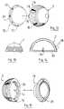
- FIGS. 1 to 7 and 12 to 11show the first “acetabular” element 1 a total hip prosthesis according to the invention.
- This first element 1has a recess in the housing 2 in the form of a spherical cap, intended to come to fit on the ball joint 3 (FIG. 7) of a second element or "femoral part 4".
- the femoral part 4ends at its upper part by a frustoconical bearing 5 on which the spherical ball joint 3 fits, this according to a well known technique.
- the first element 1is made in two parts, namely a metal outer case 6 ( Figures 1, 6, 16, 17) or 7 ( Figures 12 to 15).
- the metal case 6its implantation is carried out by screwing with the aid of screws 8 which the surgeon places in the bone of the patient's pelvis.
- several holes 9are provided distributed at different angular positions all around the spherical cap forming the housing 6.
- the surgeonchooses several of these holes 9 to engage screws 8 (for example only three or four in number.
- the internal wall of the latterhas a convergent shape which defines an inner bearing 10 in the shape of a cap This surface comes to bear on the peripheral face of the head 11 of the screw 8, peripheral face 12 which also has a wall in the form of a spherical cap.
- the surgeonhas any facility to tilt the screw 8 in one direction or the other, while its head 11 retains a good range in the hole 9.
- the insert 13 to be snapped into the metal case 6is made of a synthetic material such as for example polyethylene. Its snapping into the housing 6 is facilitated by air ejection cones 14 provided in the hollow on the internal face thereof. Furthermore, an indexing device is provided for defining the angular position of the insert 13 in the metal case 6. This indexing device may include a lug 15 protruding outside the bearing face 16 of the case 6, to allow it to be engaged in one or other of the notches 17 provided facing around the insert 13.
- the insert 13is thus positioned very exactly in the pelvic bone, it is advantageous to provide in what will be its upper external part, an protruding part or "visor” 21 capable of preventing any untimely dislodging of the ball joint 3 a once implanted the prosthesis.
- This "visor" 21is therefore called upon to play an antiluxation role.
- peripheral rib 22in relief around the insert 13, which allows a snap-fastening in the internal peripheral groove 24 provided opposite in the housing 6 or 7.
- the flared zone 26has its outer wall coated with a porous structure 27 facilitating as before the bone rehabitation around the prosthesis.
Landscapes
- Health & Medical Sciences (AREA)
- Orthopedic Medicine & Surgery (AREA)
- Cardiology (AREA)
- Oral & Maxillofacial Surgery (AREA)
- Transplantation (AREA)
- Engineering & Computer Science (AREA)
- Biomedical Technology (AREA)
- Heart & Thoracic Surgery (AREA)
- Vascular Medicine (AREA)
- Life Sciences & Earth Sciences (AREA)
- Animal Behavior & Ethology (AREA)
- General Health & Medical Sciences (AREA)
- Public Health (AREA)
- Veterinary Medicine (AREA)
- Prostheses (AREA)
- Materials For Medical Uses (AREA)
Abstract
Description
Translated fromFrenchLa présente invention est relative à une prothèse chirurgicale totale du genre de celles qu'on implante dans la hanche d'un patient en remplacement de l'articulation naturelle. Une telle prothèse totale comprend, d'une part une partie fémorale, d'autre part un cotyle.The present invention relates to a total surgical prosthesis of the kind that is implanted in the hip of a patient to replace the natural joint. Such a total prosthesis comprises, on the one hand a femoral part, on the other hand a acetabulum.
Il existe de nombreux types de prothèses totales de la hanche, mais la plupart présentent divers inconvénients.There are many types of total hip replacement, but most have various disadvantages.
En particulier, il arrive qu'à la longue la partie fémorale se désolidarise plus ou moins de l'os du fémur, ou amorce un basculement à l'intérieur de celui-ci, généralement en varus. En ce qui concerne le cotyle, sa fixation et son immobilisation dans l'os du bassin laissent souvent à désirer. Enfin, certaines prothèses connues sont sujettes au risque de luxation après implantation sur le patient.In particular, it happens that in the long run the femoral part dissociates more or less from the bone of the femur, or initiates a tilting inside of it, generally in varus. With regard to the acetabulum, its fixation and immobilization in the pelvic bone often leaves something to be desired. Finally, certain known prostheses are subject to the risk of dislocation after implantation on the patient.
La présente invention a pour but d'éviter ces inconvénients en réalisant une prothèse totale de hanche dont l'implantation soit par ailleurs aisée pour le chirurgien, tout en permettant une adaptation à chaque cas pathologique.The object of the present invention is to avoid these drawbacks by producing a total hip prosthesis, the implantation of which is moreover easy for the surgeon, while allowing adaptation to each pathological case.
Une prothèse totale de la hanche selon l'invention comprend :
- d'une part un premier élément ou "cotyle" à implanter dans le bassin du patient ;
- d'autre part un deuxième élément ou "pièce fémorale" à implanter dans la partie supérieure de la cavité médullaire du fémur, cette pièce fémorale comportant une tête supérieure à rotule et une queue d'implantation inférieure, et elle est caractérisée en ce que :
- d'une part le premier élément est réalisé en deux pièces, à savoir un boîtier extérieur métallique et un insert en une matière synthétique définissant le logement sphérique de la rotule ;
- d'autre part la queue de la pièce fémorale possède une forme extérieure définissant deux zones successives, à savoir une zone distale cylindrique et une zone proximale évasée vers le haut dans les quatre directions.
- on the one hand, a first element or "cup" to be implanted in the patient's pelvis;
- on the other hand, a second element or "femoral part" to be implanted in the upper part of the medullary cavity of the femur, this femoral part comprising an upper ball-head and a lower implantation tail, and it is characterized in that:
- on the one hand, the first element is made in two parts, namely a metal outer casing and an insert in a synthetic material defining the spherical housing of the ball joint;
- on the other hand the tail of the femoral part has an external shape defining two successive zones, namely a distal cylindrical zone and a proximal zone flared upwards in the four directions.
Suivant une autre caractéristique de l'invention, le boîtier métallique du premier élément est cimenté dans l'os du bassin au moyen d'un ciment acrylique.According to another characteristic of the invention, the metal casing of the first element is cemented in the bone of the pelvis by means of an acrylic cement.
Suivant une autre caractéristique de l'invention, le boîtier métallique du premier élément est fixé dans l'os du bassin au moyen de vis.According to another characteristic of the invention, the metal case of the first element is fixed in the bone of the pelvis by means of screws.
- Suivant une autre caractéristique de l'invention, le boîtier métallique du premier élément possède une paroi extérieure revêtue d'une structure poreuse pour faciliter la réhabitation osseuse nécessaire pour une fixation sans ciment.- According to another characteristic of the invention, the metal case of the first element has an outer wall coated with a porous structure to facilitate the bone rehabitation necessary for fixing without cement.
Suivant une autre caractéristique de l'invention, la partie externe du boîtier métallique du premier élément possède des cônes d'éjection dessinés en creux pour faciliter le passage du ciment lors d'une fixation cimentée.According to another characteristic of the invention, the external part of the metal housing of the first element has ejection cones drawn in hollow to facilitate the passage of the cement during a cemented fixing.
Suivant une autre caractéristique de l'invention, le premier élément comporte un dispositif d'indexage par ergot et encoches pour définir parmi plusieurs orientations possibles la position angulaire de l'insert à l'intérieur du boîtier métallique.According to another characteristic of the invention, the first element comprises an indexing device by lug and notches to define among several possible orientations the angular position of the insert inside the metal case.
Suivant une autre caractéristique de l'invention, l'insert est en polyéthylène.According to another characteristic of the invention, the insert is made of polyethylene.
Suivant une autre caractéristique de l'invention, le boîtier métallique du premier élément possède des cônes d'éjection d'air, pour faciliter l'encliquetage de l'insert en polyéthylène dans le boîtier métallique.According to another characteristic of the invention, the metal casing of the first element has air ejection cones, to facilitate the snap-fastening of the polyethylene insert into the metal casing.
Suivant une autre caractéristique de l'invention, la fixation biologique de la queue de la pièce fémorale dans l'os du fémur s'effectue uniquement au niveau de la zone proximale. Cela évite les risques de descellement ou de voir le malade soumis à des douleurs.According to another characteristic of the invention, the biological fixation of the tail of the femoral part in the bone of the femur is carried out only at the level of the proximal zone. This avoids the risk of loosening or seeing the patient subjected to pain.
Suivant une autre caractéristique de l'invention, la zone proximale évasée de la pièce fémorale est revêtue d'une structure poreuse facilitant la réhabitation osseuse.According to another characteristic of the invention, the flared proximal area of the femoral piece is coated with a porous structure facilitating bone rehabitation.
Le dessin annexé donné à titre d'exemple non limitatif permettra de mieux comprendre les caractéristiques de l'invention et les avantages qu'elle est susceptible de lui procurer.
- la figure 1 est une vue en perspective montrant le boîtier métallique du premier élément, dans le cas d'une fixation sans ciment, au moyen de vis.
- la figure 2 est une vue en plan d'une variante, montrant les huit encoches périphériques pour le positionnement angulaire, d'un insert en polyéthylène.
- la figure 3 est une vue en coupe diamétrale de l'élément de la figure 1.
- la figure 4 montre à grande échelle un détail correspondant à la structure de revêtement poreuse.
- la figure 5 est une coupe diamétrale d'un mode de réalisation de l'insert en polyéthylène.
- la figure 6 est une coupe correspondant à un détail de la figure 1 et montrant la forme sphérique de l'appui d'une tête de vis.
- la figure 7 est un schéma d'ensemble montrant la prothèse selon l'invention après assemblage.
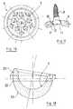
- la figure 8 est une vue de face de la pièce fémorale dépourvue de sa sphère d'articulation.
- la figure 9 en est une vue latérale.
- la figure 10 montre une variante où la zone proximale évasée est revêtue d'une structure poreuse.
- la figure 11 est une coupe montrant cette partie de la pièce fémorale après son implantation dans le fémur.
- la figure 12 est une vue éclatée montrant l'insert et le boîtier métallique avant leur encliquetage l'un dans l'autre.
- la figure 13 est une vue latérale du boîtier.
- la figure 14 en est une coupe diamétrale à plus grande échelle.
- la figure 15 montre sous un angle différent le boîtier et l'insert avant leur assemblage.
- la figure 16 est une vue en plan de la face inférieure d'un boîtier métallique, dans sa variante à fixation vissée.
- la figure 17 montre la tête à appui sphérique d'une des vis de fixation de ce boîtier.
- la figure 18 est une coupe diamétrale de l'insert, dans une variante comportant une "visière" antiluxation.
- Figure 1 is a perspective view showing the metal housing of the first element, in the case of a cementless fixing, by means of screws.
- Figure 2 is a plan view of a variant, showing the eight peripheral notches for angular positioning, of a polyethylene insert.
- FIG. 3 is a diametrical sectional view of the element in FIG. 1.
- Figure 4 shows on a large scale a detail corresponding to the porous coating structure.
- Figure 5 is a diametrical section of an embodiment of the polyethylene insert.
- Figure 6 is a section corresponding to a detail in Figure 1 and showing the spherical shape of the support of a screw head.
- Figure 7 is an overall diagram showing the prosthesis according to the invention after assembly.
- Figure 8 is a front view of the femoral part devoid of its articulation sphere.
- Figure 9 is a side view.
- Figure 10 shows a variant where the flared proximal area is coated with a porous structure.
- Figure 11 is a section showing this part of the femoral part after its implantation in the femur.
- Figure 12 is an exploded view showing the insert and the metal housing before they snap into one another.
- Figure 13 is a side view of the housing.
- Figure 14 is a diametrical section on a larger scale.
- Figure 15 shows from a different angle the housing and the insert before their assembly.
- Figure 16 is a plan view of the underside of a metal housing, in its variant with screw fixing.
- FIG. 17 shows the head with spherical support of one of the fixing screws of this housing.
- Figure 18 is a diametrical section of the insert, in a variant comprising a "visor" antiluxation.
On a représenté sur les figure 1 à 7 et 12 à 11 le premier élément "cotyle" 1 une prothèse totale de la hanche selon l'invention. Ce premier élément 1 possède en creux un logement 2 en forme de calotte sphérique, destiné à venir s adapter sur la rotule 3 (figure 7) d'un deuxième élément ou "pièce fémorale 4". Dans l'exemple choisi, on a supposé que la pièce fémorale 4 se termine à sa partie supérieure par une portée tronconique 5 sur laquelle vient s'emboîter la rotule sphérique 3, ceci suivant une technique bien connue.FIGS. 1 to 7 and 12 to 11 show the first “acetabular” element 1 a total hip prosthesis according to the invention. This first element 1 has a recess in the
Selon l'invention, le premier élément 1 est réalisé en deux pièces, à savoir un boîtier extérieur métallique 6 (figures 1, 6, 16, 17) ou 7 (figures 12 à 15).According to the invention, the first element 1 is made in two parts, namely a metal outer case 6 (Figures 1, 6, 16, 17) or 7 (Figures 12 to 15).
En ce qui concerne le boîtier métallique 6, son implantation s'effectue par vissage à l'aide de vis 8 que le chirurgien met en place dans l'os du bassin du patient. Pour cela, on prévoit plusieurs trous 9 répartis à différentes positions angulaires tout autour de la calotte sphérique formant le boîtier 6. En fonction de l'état du patient, le chirurgien choisit plusieurs de ces trous 9 pour y engager des vis 8 (par exemple seulement au nombre de trois ou quatre. Pour faciliter encore cette implantation et notamment le choix de l'inclinaison de chaque vis 8 dans son trou 9, la paroi interne de ce dernier présente une forme convergente qui définit une portée intérieure 10 en forme de calotte sphérique. Sur cette portée vient prendre appui la face périphérique de la tête 11 de la vis 8, face périphérique 12 qui possède elle aussi une paroi en forme de calotte sphérique. Ainsi, on comprend que le chirurgien ait toute facilité pour incliner la vis 8 dans une direction ou dans l'autre, tandis que sa tête 11 conserve une bonne portée dans le trou 9.As regards the
L'insert 13 à encliqueter dans le boîtier métallique 6 est réalisé en une matière synthétique telle que par exemple de polyéthylène. Son encliquetage dans le boîtier 6 est facilité par des cônes d'éjection d'air 14 prévus en creux dans la face interne de celui-ci. Par ailleurs, un dispositif d'indexage est prévu pour définir la position angulaire de l'insert 13 dans le boîtier métallique 6. Ce dispositif d'indexage peut comporter un ergot 15 dépassant hors de la face d'appui 16 du boîtier 6, pour permettre de l'engager dans l'une ou l'autre des encoches 17 prévues en regard autour de l'insert 13.The
Dans la variante des figures 12 à 15, la fixation du boîtier 7 dans l'os du bassin du patient s'effectue, non plus par des vis, mais à l'aide d'un ciment. Pour cela, on prévoit sur la paroi extérieure du boîtier 7 :
- d'une part des rainures périphériques 18 facilitant l'accrochage du ciment ;
- d'autre part des cônes d'éjection 19 dessinés en creux sur l'extérieur du boîtier 7, pour que le ciment encore liquide puisse baver au moment de l'implantation dans l'os.
- on the one hand,
peripheral grooves 18 facilitating the attachment of the cement; - on the other
hand ejection cones 19 hollowed out on the outside of the housing 7, so that the still liquid cement can drool at the time of implantation in the bone.
Dans tous les cas, que le boîtier 6 ou 7 soit vissé ou cimenté, il est avantageux de revêtir sa surface extérieure au moyen d'une structure poreuse 20 (figure 4) destinée à faciliter la fixation, par réhabitation de l'os environnant qui prolifère dans cette structure 20.In all cases, whether the
L'insert 13 étant ainsi positionné très exactement dans l'os du bassin, il est avantageux de prévoir à ce qui sera sa partie supérieure externe, une partie dépassante ou "visière" 21 susceptible d'empêcher tout déboîtement intempestif de la rotule 3 une fois implantée la prothèse. Cette "visière" 21 est donc appelée à jouer un rôle antiluxation.The
Enfin, pour améliorer encore l'assemblage du premier et du deuxième élément, on prévoit avantageusement une nervure périphérique 22 en relief autour de l'insert 13, ce qui permet un encliquetage dans la gorge périphérique interne 24 prévue en regard dans le boîtier 6 ou 7.Finally, to further improve the assembly of the first and second elements, there is advantageously provided a
En ce qui concerne la pièce fémorale 4 selon l'invention, sa queue présente la particularité d'être définie par deux zones successives 25 et 26, à savoir :
- une zone distale cylindrique 25 prévue pour assurer un bon guidage dans la cavité médullaire du fémur :
une zone proximale 26, évasée vers le haut dans les quatre directions (figures 7 à 11) pour assurer une bonne répartition des efforts de poussée dus au poids du corps du patient.
- a cylindrical
distal zone 25 provided to ensure good guidance in the medullary cavity of the femur: - a
proximal zone 26, flared upwards in the four directions (FIGS. 7 to 11) to ensure a good distribution of the thrust forces due to the weight of the patient's body.
Suivant un mode de réalisation préféré, la zone évasée 26 a sa paroi extérieure revêtue d'une structure poreuse 27 facilitant comme précédemment la réhabitation osseuse autour de la prothèse.According to a preferred embodiment, the flared
Claims (11)
Translated fromFrenchPriority Applications (5)
| Application Number | Priority Date | Filing Date | Title |
|---|---|---|---|
| FR898914239AFR2653326B1 (en) | 1989-10-24 | 1989-10-24 | TOTAL HIP PROSTHESIS. |
| AT90440103TATE148830T1 (en) | 1989-10-24 | 1990-11-16 | HIP JOINT PROSTHESIS |
| EP90440103AEP0485678B1 (en) | 1989-10-24 | 1990-11-16 | Hip joint prosthesis |
| DE69029945TDE69029945T2 (en) | 1989-10-24 | 1990-11-16 | Hip prosthesis |
| ES90440103TES2099706T3 (en) | 1989-10-24 | 1990-11-16 | TOTAL HIP PROSTHESIS. |
Applications Claiming Priority (2)
| Application Number | Priority Date | Filing Date | Title |
|---|---|---|---|
| FR898914239AFR2653326B1 (en) | 1989-10-24 | 1989-10-24 | TOTAL HIP PROSTHESIS. |
| EP90440103AEP0485678B1 (en) | 1989-10-24 | 1990-11-16 | Hip joint prosthesis |
Publications (2)
| Publication Number | Publication Date |
|---|---|
| EP0485678A1true EP0485678A1 (en) | 1992-05-20 |
| EP0485678B1 EP0485678B1 (en) | 1997-02-12 |
Family
ID=26127744
Family Applications (1)
| Application Number | Title | Priority Date | Filing Date |
|---|---|---|---|
| EP90440103AExpired - LifetimeEP0485678B1 (en) | 1989-10-24 | 1990-11-16 | Hip joint prosthesis |
Country Status (5)
| Country | Link |
|---|---|
| EP (1) | EP0485678B1 (en) |
| AT (1) | ATE148830T1 (en) |
| DE (1) | DE69029945T2 (en) |
| ES (1) | ES2099706T3 (en) |
| FR (1) | FR2653326B1 (en) |
Cited By (23)
| Publication number | Priority date | Publication date | Assignee | Title |
|---|---|---|---|---|
| EP0687452A1 (en)* | 1994-06-16 | 1995-12-20 | Patrick Marie Croly Labourdette | Acetabular cup prosthesis, its use and ancillary instrument for inserting the same |
| EP0680735A3 (en)* | 1993-03-18 | 1996-01-17 | Levante Ind Quirurgicas | Modular cup. |
| WO1997042913A1 (en)* | 1996-05-14 | 1997-11-20 | Bruno Balay | Cotyloidal implant fixed without cement |
| FR2748654A1 (en)* | 1996-05-14 | 1997-11-21 | Setiey Louis | Cotyloid implant cup |
| FR2748655A1 (en)* | 1996-05-14 | 1997-11-21 | Setiey Louis | Cotyloid implant cup |
| WO1999022674A1 (en)* | 1997-10-31 | 1999-05-14 | Sulzer Orthopedics Inc. | Locking mechanism for acetabular cup |
| US8123815B2 (en) | 2008-11-24 | 2012-02-28 | Biomet Manufacturing Corp. | Multiple bearing acetabular prosthesis |
| US8308810B2 (en) | 2009-07-14 | 2012-11-13 | Biomet Manufacturing Corp. | Multiple bearing acetabular prosthesis |
| US8679187B2 (en) | 2006-03-20 | 2014-03-25 | Smith & Nephew, Inc. | Acetabular cup assembly for multiple bearing materials |
| US9662126B2 (en) | 2009-04-17 | 2017-05-30 | Arthrosurface Incorporated | Glenoid resurfacing system and method |
| US9861492B2 (en) | 2014-03-07 | 2018-01-09 | Arthrosurface Incorporated | Anchor for an implant assembly |
| US9931211B2 (en) | 2003-02-24 | 2018-04-03 | Arthrosurface Incorporated | Trochlear resurfacing system and method |
| US10045788B2 (en) | 2006-12-11 | 2018-08-14 | Arthrosurface Incorporated | Retrograde resection apparatus and method |
| US10076343B2 (en) | 2002-12-03 | 2018-09-18 | Arthrosurface Incorporated | System for articular surface replacement |
| US10307172B2 (en) | 2012-07-03 | 2019-06-04 | Arthrosurface Incorporated | System and method for joint resurfacing and repair |
| US10624748B2 (en) | 2014-03-07 | 2020-04-21 | Arthrosurface Incorporated | System and method for repairing articular surfaces |
| US10624752B2 (en) | 2006-07-17 | 2020-04-21 | Arthrosurface Incorporated | Tibial resurfacing system and method |
| US10695096B2 (en) | 2013-04-16 | 2020-06-30 | Arthrosurface Incorporated | Suture system and method |
| US10945743B2 (en) | 2009-04-17 | 2021-03-16 | Arthrosurface Incorporated | Glenoid repair system and methods of use thereof |
| US11160663B2 (en) | 2017-08-04 | 2021-11-02 | Arthrosurface Incorporated | Multicomponent articular surface implant |
| US11478358B2 (en) | 2019-03-12 | 2022-10-25 | Arthrosurface Incorporated | Humeral and glenoid articular surface implant systems and methods |
| US11607319B2 (en) | 2014-03-07 | 2023-03-21 | Arthrosurface Incorporated | System and method for repairing articular surfaces |
| US11712276B2 (en) | 2011-12-22 | 2023-08-01 | Arthrosurface Incorporated | System and method for bone fixation |
Families Citing this family (22)
| Publication number | Priority date | Publication date | Assignee | Title |
|---|---|---|---|---|
| FR2681238A1 (en)* | 1991-09-13 | 1993-03-19 | Impact | COTYL FOR PROTHESIS OF HIP. |
| FR2682588B1 (en)* | 1991-10-22 | 1995-09-08 | Lepine Groupe | COTYLOUIDIAN IMPLANT. |
| US5358532A (en)* | 1992-06-16 | 1994-10-25 | Smith & Nephew Richards Inc. | Cementless acetabular cup |
| FR2749753B1 (en) | 1996-06-14 | 1998-12-24 | Mosseri Raphael | TOTAL HIP PROSTHESIS FOR ENDO-ARTICULAR PLACEMENT AND ITS ANCILLARY DEVICE |
| US6610067B2 (en) | 2000-05-01 | 2003-08-26 | Arthrosurface, Incorporated | System and method for joint resurface repair |
| US7678151B2 (en) | 2000-05-01 | 2010-03-16 | Ek Steven W | System and method for joint resurface repair |
| AU2005202099B2 (en)* | 2000-05-01 | 2007-06-07 | Arthrosurface, Incorporated | System and method for joint resurface repair |
| US7713305B2 (en) | 2000-05-01 | 2010-05-11 | Arthrosurface, Inc. | Articular surface implant |
| US7618462B2 (en) | 2000-05-01 | 2009-11-17 | Arthrosurface Incorporated | System and method for joint resurface repair |
| US7163541B2 (en) | 2002-12-03 | 2007-01-16 | Arthrosurface Incorporated | Tibial resurfacing system |
| US6520964B2 (en) | 2000-05-01 | 2003-02-18 | Std Manufacturing, Inc. | System and method for joint resurface repair |
| US8177841B2 (en) | 2000-05-01 | 2012-05-15 | Arthrosurface Inc. | System and method for joint resurface repair |
| US7914545B2 (en) | 2002-12-03 | 2011-03-29 | Arthrosurface, Inc | System and method for retrograde procedure |
| US7901408B2 (en) | 2002-12-03 | 2011-03-08 | Arthrosurface, Inc. | System and method for retrograde procedure |
| AU2004293042A1 (en) | 2003-11-20 | 2005-06-09 | Arthrosurface, Inc. | Retrograde delivery of resurfacing devices |
| US7951163B2 (en) | 2003-11-20 | 2011-05-31 | Arthrosurface, Inc. | Retrograde excision system and apparatus |
| US7828853B2 (en) | 2004-11-22 | 2010-11-09 | Arthrosurface, Inc. | Articular surface implant and delivery system |
| EP2262448A4 (en) | 2008-03-03 | 2014-03-26 | Arthrosurface Inc | Bone resurfacing system and method |
| AU2010236182A1 (en) | 2009-04-17 | 2011-11-24 | Arthrosurface Incorporated | Glenoid resurfacing system and method |
| US9066716B2 (en) | 2011-03-30 | 2015-06-30 | Arthrosurface Incorporated | Suture coil and suture sheath for tissue repair |
| FR2996118B1 (en) | 2012-10-03 | 2014-10-10 | Stephane Denjean | CUPULAR FOR COTYLOID IMPLANT INTENDED TO BE IMPLANTED IN AN ACETABULAR CAVITY |
| CN106137467A (en)* | 2016-08-17 | 2016-11-23 | 优适医疗科技(苏州)有限公司 | A kind of acetabular cup for artificial hip joint |
Citations (7)
| Publication number | Priority date | Publication date | Assignee | Title |
|---|---|---|---|---|
| DE2911754A1 (en)* | 1979-03-26 | 1980-10-09 | Hans Dr Reimer | Artificial hip joint socket - has peripheral ribs decreasing in dia. towards zenith and hammered into bone |
| FR2583286A1 (en)* | 1985-06-14 | 1986-12-19 | Botton Gerard De | Femoral prosthesis, femoral piece for such a prosthesis and instrument for positioning the prosthesis |
| US4695282A (en)* | 1986-01-23 | 1987-09-22 | Osteonics Corp. | Acetabular cup assembly with selective bearing face orientation |
| FR2598609A1 (en)* | 1986-05-16 | 1987-11-20 | Courtois Serge | Hip prosthesis |
| EP0313762A1 (en)* | 1987-10-28 | 1989-05-03 | GebràDer Sulzer Aktiengesellschaft | Two-piece acetabular cup |
| US4840632A (en)* | 1984-03-16 | 1989-06-20 | Kampner Stanley L | Hip prosthesis |
| FR2638962A1 (en)* | 1988-11-15 | 1990-05-18 | Biomecanique Integree | Stem for fixing the male part of a hip prosthesis ball joint |
- 1989
- 1989-10-24FRFR898914239Apatent/FR2653326B1/ennot_activeExpired - Lifetime
- 1990
- 1990-11-16ESES90440103Tpatent/ES2099706T3/ennot_activeExpired - Lifetime
- 1990-11-16ATAT90440103Tpatent/ATE148830T1/ennot_activeIP Right Cessation
- 1990-11-16EPEP90440103Apatent/EP0485678B1/ennot_activeExpired - Lifetime
- 1990-11-16DEDE69029945Tpatent/DE69029945T2/ennot_activeExpired - Fee Related
Patent Citations (7)
| Publication number | Priority date | Publication date | Assignee | Title |
|---|---|---|---|---|
| DE2911754A1 (en)* | 1979-03-26 | 1980-10-09 | Hans Dr Reimer | Artificial hip joint socket - has peripheral ribs decreasing in dia. towards zenith and hammered into bone |
| US4840632A (en)* | 1984-03-16 | 1989-06-20 | Kampner Stanley L | Hip prosthesis |
| FR2583286A1 (en)* | 1985-06-14 | 1986-12-19 | Botton Gerard De | Femoral prosthesis, femoral piece for such a prosthesis and instrument for positioning the prosthesis |
| US4695282A (en)* | 1986-01-23 | 1987-09-22 | Osteonics Corp. | Acetabular cup assembly with selective bearing face orientation |
| FR2598609A1 (en)* | 1986-05-16 | 1987-11-20 | Courtois Serge | Hip prosthesis |
| EP0313762A1 (en)* | 1987-10-28 | 1989-05-03 | GebràDer Sulzer Aktiengesellschaft | Two-piece acetabular cup |
| FR2638962A1 (en)* | 1988-11-15 | 1990-05-18 | Biomecanique Integree | Stem for fixing the male part of a hip prosthesis ball joint |
Cited By (41)
| Publication number | Priority date | Publication date | Assignee | Title |
|---|---|---|---|---|
| EP0680735A3 (en)* | 1993-03-18 | 1996-01-17 | Levante Ind Quirurgicas | Modular cup. |
| FR2721201A1 (en)* | 1994-06-16 | 1995-12-22 | Labourdette Patrick Marie Crol | Cotyloid prosthesis |
| EP0687452A1 (en)* | 1994-06-16 | 1995-12-20 | Patrick Marie Croly Labourdette | Acetabular cup prosthesis, its use and ancillary instrument for inserting the same |
| US6231612B1 (en) | 1996-05-14 | 2001-05-15 | Bruno Balay | Acetabular implant fixed without cement |
| WO1997042913A1 (en)* | 1996-05-14 | 1997-11-20 | Bruno Balay | Cotyloidal implant fixed without cement |
| FR2748654A1 (en)* | 1996-05-14 | 1997-11-21 | Setiey Louis | Cotyloid implant cup |
| FR2748655A1 (en)* | 1996-05-14 | 1997-11-21 | Setiey Louis | Cotyloid implant cup |
| WO1999022674A1 (en)* | 1997-10-31 | 1999-05-14 | Sulzer Orthopedics Inc. | Locking mechanism for acetabular cup |
| US10076343B2 (en) | 2002-12-03 | 2018-09-18 | Arthrosurface Incorporated | System for articular surface replacement |
| US10624749B2 (en) | 2003-02-24 | 2020-04-21 | Arthrosurface Incorporated | Trochlear resurfacing system and method |
| US11337819B2 (en) | 2003-02-24 | 2022-05-24 | Arthrosurface Incorporated | Trochlear resurfacing system and method |
| US9931211B2 (en) | 2003-02-24 | 2018-04-03 | Arthrosurface Incorporated | Trochlear resurfacing system and method |
| US8679187B2 (en) | 2006-03-20 | 2014-03-25 | Smith & Nephew, Inc. | Acetabular cup assembly for multiple bearing materials |
| US10624752B2 (en) | 2006-07-17 | 2020-04-21 | Arthrosurface Incorporated | Tibial resurfacing system and method |
| US11471289B2 (en) | 2006-07-17 | 2022-10-18 | Arthrosurface Incorporated | Tibial resurfacing system and method |
| US10045788B2 (en) | 2006-12-11 | 2018-08-14 | Arthrosurface Incorporated | Retrograde resection apparatus and method |
| US10959740B2 (en) | 2006-12-11 | 2021-03-30 | Arthrosurface Incorporated | Retrograde resection apparatus and method |
| US9445903B2 (en) | 2008-11-24 | 2016-09-20 | Biomet Manufacturing, Llc | Multi-bearing acetabular prosthesis |
| US8123815B2 (en) | 2008-11-24 | 2012-02-28 | Biomet Manufacturing Corp. | Multiple bearing acetabular prosthesis |
| US11478259B2 (en) | 2009-04-17 | 2022-10-25 | Arthrosurface, Incorporated | Glenoid resurfacing system and method |
| US10945743B2 (en) | 2009-04-17 | 2021-03-16 | Arthrosurface Incorporated | Glenoid repair system and methods of use thereof |
| US9662126B2 (en) | 2009-04-17 | 2017-05-30 | Arthrosurface Incorporated | Glenoid resurfacing system and method |
| US10478200B2 (en) | 2009-04-17 | 2019-11-19 | Arthrosurface Incorporated | Glenoid resurfacing system and method |
| US9445904B2 (en) | 2009-07-14 | 2016-09-20 | Biomet Manufacturing, Llc | Multiple bearing acetabular prosthesis |
| US8308810B2 (en) | 2009-07-14 | 2012-11-13 | Biomet Manufacturing Corp. | Multiple bearing acetabular prosthesis |
| US11712276B2 (en) | 2011-12-22 | 2023-08-01 | Arthrosurface Incorporated | System and method for bone fixation |
| US10307172B2 (en) | 2012-07-03 | 2019-06-04 | Arthrosurface Incorporated | System and method for joint resurfacing and repair |
| US11191552B2 (en) | 2012-07-03 | 2021-12-07 | Arthrosurface, Incorporated | System and method for joint resurfacing and repair |
| US11648036B2 (en) | 2013-04-16 | 2023-05-16 | Arthrosurface Incorporated | Suture system and method |
| US10695096B2 (en) | 2013-04-16 | 2020-06-30 | Arthrosurface Incorporated | Suture system and method |
| US10575957B2 (en) | 2014-03-07 | 2020-03-03 | Arthrosurface Incoporated | Anchor for an implant assembly |
| US11083587B2 (en) | 2014-03-07 | 2021-08-10 | Arthrosurface Incorporated | Implant and anchor assembly |
| US10624748B2 (en) | 2014-03-07 | 2020-04-21 | Arthrosurface Incorporated | System and method for repairing articular surfaces |
| US9962265B2 (en) | 2014-03-07 | 2018-05-08 | Arthrosurface Incorporated | System and method for repairing articular surfaces |
| US9931219B2 (en) | 2014-03-07 | 2018-04-03 | Arthrosurface Incorporated | Implant and anchor assembly |
| US11607319B2 (en) | 2014-03-07 | 2023-03-21 | Arthrosurface Incorporated | System and method for repairing articular surfaces |
| US10624754B2 (en) | 2014-03-07 | 2020-04-21 | Arthrosurface Incorporated | System and method for repairing articular surfaces |
| US9861492B2 (en) | 2014-03-07 | 2018-01-09 | Arthrosurface Incorporated | Anchor for an implant assembly |
| US11766334B2 (en) | 2014-03-07 | 2023-09-26 | Arthrosurface Incorporated | System and method for repairing articular surfaces |
| US11160663B2 (en) | 2017-08-04 | 2021-11-02 | Arthrosurface Incorporated | Multicomponent articular surface implant |
| US11478358B2 (en) | 2019-03-12 | 2022-10-25 | Arthrosurface Incorporated | Humeral and glenoid articular surface implant systems and methods |
Also Published As
| Publication number | Publication date |
|---|---|
| DE69029945T2 (en) | 1997-05-28 |
| FR2653326A1 (en) | 1991-04-26 |
| ES2099706T3 (en) | 1997-06-01 |
| DE69029945D1 (en) | 1997-03-27 |
| EP0485678B1 (en) | 1997-02-12 |
| ATE148830T1 (en) | 1997-02-15 |
| FR2653326B1 (en) | 1994-09-16 |
Similar Documents
| Publication | Publication Date | Title |
|---|---|---|
| EP0485678B1 (en) | Hip joint prosthesis | |
| EP1229872B1 (en) | Expansible acetabular prosthesis with double mobility | |
| EP1408886B1 (en) | Modular acetabular cup | |
| EP1510190B1 (en) | Glenoid component of a shoulder prosthesis and total shoulder prosthesis comprising such a component | |
| EP0797964A1 (en) | Assembly of elements for the formation of a total hip prosthesis | |
| EP0127503B1 (en) | Shoulder prosthesis | |
| EP1520560B1 (en) | Humeral implant for a shoulder prosthesis | |
| WO1987005490A1 (en) | Prosthesis cupula | |
| FR2478462A1 (en) | Artificial joint component securing system - uses parallel lugs pressed into holes previously bored in bone with openings in lugs for osseous invasion | |
| WO1997042913A1 (en) | Cotyloidal implant fixed without cement | |
| EP0532439B1 (en) | Acetabular cup for hip prosthesis | |
| FR2647669A1 (en) | Anatomical hip prosthesis | |
| FR2770769A1 (en) | Acetabular cup prosthesis for hip surgery | |
| FR2786390A1 (en) | CORRECTION COTYL FOR USE IN THE TREATMENT OF HIP CONDITIONS | |
| FR2686791A1 (en) | Acetabulum for hip prosthesis to be impacted, intended to be implanted without cement, consisting of an outer cup and an inner core | |
| FR2692776A1 (en) | Total replacement prosthesis for bone joint esp. in hand or foot - has cotylar portion implanted into bone surface, cooperating with shaft implanted in medullary canal of second bone via intermediate pin | |
| EP0900552B1 (en) | Acetabular implant with plugs | |
| EP0963740A1 (en) | Acetabular cup for hip prosthesis | |
| FR2819172A1 (en) | Replacement acetabular cup for hip prosthesis has angled fixed lug with fastening hole and hook to engage with pelvic aperture | |
| FR2677878A1 (en) | Acetabular prosthesis | |
| FR2598908A1 (en) | Acetabular prosthesis with cementless impacting-screwing into the acetabulum | |
| CA2586800C (en) | Acetabular prosthesis to be fixed without cement | |
| FR2516377A1 (en) | Artificial hip joint socket - has external face joined to cavity wall by spherical sector with grooved outer surface | |
| FR2668923A1 (en) | Cup for acetabular implantation, and hip prosthesis comprising this cup | |
| FR2628967A1 (en) | Total hip prosthesis with curved femoral rod - formed with fin on its convex side engaged in groove in medullar canal near greater trochanter |
Legal Events
| Date | Code | Title | Description |
|---|---|---|---|
| PUAI | Public reference made under article 153(3) epc to a published international application that has entered the european phase | Free format text:ORIGINAL CODE: 0009012 | |
| AK | Designated contracting states | Kind code of ref document:A1 Designated state(s):AT BE CH DE DK ES GB GR IT LI LU NL SE | |
| 17P | Request for examination filed | Effective date:19921120 | |
| 17Q | First examination report despatched | Effective date:19941213 | |
| GRAH | Despatch of communication of intention to grant a patent | Free format text:ORIGINAL CODE: EPIDOS IGRA | |
| GRAH | Despatch of communication of intention to grant a patent | Free format text:ORIGINAL CODE: EPIDOS IGRA | |
| GRAH | Despatch of communication of intention to grant a patent | Free format text:ORIGINAL CODE: EPIDOS IGRA | |
| GRAG | Despatch of communication of intention to grant | Free format text:ORIGINAL CODE: EPIDOS AGRA | |
| GRAA | (expected) grant | Free format text:ORIGINAL CODE: 0009210 | |
| AK | Designated contracting states | Kind code of ref document:B1 Designated state(s):AT BE CH DE DK ES GB GR IT LI LU NL SE | |
| PG25 | Lapsed in a contracting state [announced via postgrant information from national office to epo] | Ref country code:GR Free format text:LAPSE BECAUSE OF FAILURE TO SUBMIT A TRANSLATION OF THE DESCRIPTION OR TO PAY THE FEE WITHIN THE PRESCRIBED TIME-LIMIT Effective date:19970212 Ref country code:DK Effective date:19970212 Ref country code:AT Effective date:19970212 | |
| REF | Corresponds to: | Ref document number:148830 Country of ref document:AT Date of ref document:19970215 Kind code of ref document:T | |
| REG | Reference to a national code | Ref country code:CH Ref legal event code:EP | |
| ITF | It: translation for a ep patent filed | ||
| REF | Corresponds to: | Ref document number:69029945 Country of ref document:DE Date of ref document:19970327 | |
| PG25 | Lapsed in a contracting state [announced via postgrant information from national office to epo] | Ref country code:SE Effective date:19970512 | |
| REG | Reference to a national code | Ref country code:ES Ref legal event code:FG2A Ref document number:2099706 Country of ref document:ES Kind code of ref document:T3 | |
| GBT | Gb: translation of ep patent filed (gb section 77(6)(a)/1977) | Effective date:19970516 | |
| PG25 | Lapsed in a contracting state [announced via postgrant information from national office to epo] | Ref country code:LU Free format text:LAPSE BECAUSE OF NON-PAYMENT OF DUE FEES Effective date:19971130 | |
| PLBE | No opposition filed within time limit | Free format text:ORIGINAL CODE: 0009261 | |
| STAA | Information on the status of an ep patent application or granted ep patent | Free format text:STATUS: NO OPPOSITION FILED WITHIN TIME LIMIT | |
| 26N | No opposition filed | ||
| REG | Reference to a national code | Ref country code:GB Ref legal event code:IF02 | |
| PGFP | Annual fee paid to national office [announced via postgrant information from national office to epo] | Ref country code:CH Payment date:20041015 Year of fee payment:15 | |
| PGFP | Annual fee paid to national office [announced via postgrant information from national office to epo] | Ref country code:LU Payment date:20041018 Year of fee payment:15 | |
| PGFP | Annual fee paid to national office [announced via postgrant information from national office to epo] | Ref country code:NL Payment date:20041020 Year of fee payment:15 | |
| PGFP | Annual fee paid to national office [announced via postgrant information from national office to epo] | Ref country code:GB Payment date:20041102 Year of fee payment:15 | |
| PGFP | Annual fee paid to national office [announced via postgrant information from national office to epo] | Ref country code:DE Payment date:20041109 Year of fee payment:15 | |
| PGFP | Annual fee paid to national office [announced via postgrant information from national office to epo] | Ref country code:ES Payment date:20041112 Year of fee payment:15 | |
| PGFP | Annual fee paid to national office [announced via postgrant information from national office to epo] | Ref country code:BE Payment date:20041208 Year of fee payment:15 | |
| PG25 | Lapsed in a contracting state [announced via postgrant information from national office to epo] | Ref country code:IT Free format text:LAPSE BECAUSE OF NON-PAYMENT OF DUE FEES Effective date:20051116 Ref country code:GB Free format text:LAPSE BECAUSE OF NON-PAYMENT OF DUE FEES Effective date:20051116 | |
| PG25 | Lapsed in a contracting state [announced via postgrant information from national office to epo] | Ref country code:ES Free format text:LAPSE BECAUSE OF NON-PAYMENT OF DUE FEES Effective date:20051117 | |
| PG25 | Lapsed in a contracting state [announced via postgrant information from national office to epo] | Ref country code:LI Free format text:LAPSE BECAUSE OF NON-PAYMENT OF DUE FEES Effective date:20051130 Ref country code:CH Free format text:LAPSE BECAUSE OF NON-PAYMENT OF DUE FEES Effective date:20051130 Ref country code:BE Free format text:LAPSE BECAUSE OF NON-PAYMENT OF DUE FEES Effective date:20051130 | |
| PG25 | Lapsed in a contracting state [announced via postgrant information from national office to epo] | Ref country code:NL Free format text:LAPSE BECAUSE OF NON-PAYMENT OF DUE FEES Effective date:20060601 Ref country code:DE Free format text:LAPSE BECAUSE OF NON-PAYMENT OF DUE FEES Effective date:20060601 | |
| REG | Reference to a national code | Ref country code:CH Ref legal event code:PL | |
| GBPC | Gb: european patent ceased through non-payment of renewal fee | Effective date:20051116 | |
| NLV4 | Nl: lapsed or anulled due to non-payment of the annual fee | Effective date:20060601 | |
| REG | Reference to a national code | Ref country code:ES Ref legal event code:FD2A Effective date:20051117 | |
| BERE | Be: lapsed | Owner name:SOC. CIVILE *ESSOR Effective date:20051130 |