EP0484725A1 - Instrument for penetrating body tissue - Google Patents
Instrument for penetrating body tissueDownload PDFInfo
- Publication number
- EP0484725A1 EP0484725A1EP19910117958EP91117958AEP0484725A1EP 0484725 A1EP0484725 A1EP 0484725A1EP 19910117958EP19910117958EP 19910117958EP 91117958 AEP91117958 AEP 91117958AEP 0484725 A1EP0484725 A1EP 0484725A1
- Authority
- EP
- European Patent Office
- Prior art keywords
- tip
- instrument according
- window
- optics
- trocar
- Prior art date
- Legal status (The legal status is an assumption and is not a legal conclusion. Google has not performed a legal analysis and makes no representation as to the accuracy of the status listed.)
- Granted
Links
- 230000000149penetrating effectEffects0.000titleclaimsdescription12
- 230000003287optical effectEffects0.000claimsdescription13
- 230000003667anti-reflective effectEffects0.000claimsdescription2
- 238000005286illuminationMethods0.000claims2
- 239000004020conductorSubstances0.000abstract1
- 210000001519tissueAnatomy0.000description19
- 210000003815abdominal wallAnatomy0.000description13
- 210000004303peritoneumAnatomy0.000description10
- 210000000683abdominal cavityAnatomy0.000description9
- 230000006378damageEffects0.000description9
- 208000027418Wounds and injuryDiseases0.000description8
- 208000014674injuryDiseases0.000description8
- 230000035515penetrationEffects0.000description8
- 210000000569greater omentumAnatomy0.000description6
- 210000000056organAnatomy0.000description6
- 239000013307optical fiberSubstances0.000description5
- 210000000936intestineAnatomy0.000description4
- 239000003365glass fiberSubstances0.000description3
- VVQNEPGJFQJSBK-UHFFFAOYSA-NMethyl methacrylateChemical compoundCOC(=O)C(C)=CVVQNEPGJFQJSBK-UHFFFAOYSA-N0.000description2
- 229920005372Plexiglas®Polymers0.000description2
- VYPSYNLAJGMNEJ-UHFFFAOYSA-NSilicium dioxideChemical compoundO=[Si]=OVYPSYNLAJGMNEJ-UHFFFAOYSA-N0.000description2
- 229910000831SteelInorganic materials0.000description2
- 230000003187abdominal effectEffects0.000description2
- 210000004204blood vesselAnatomy0.000description2
- 239000000835fiberSubstances0.000description2
- 239000011521glassSubstances0.000description2
- 210000000813small intestineAnatomy0.000description2
- 239000010959steelSubstances0.000description2
- 241000251468ActinopterygiiSpecies0.000description1
- 240000007124Brassica oleraceaSpecies0.000description1
- 235000003899Brassica oleracea var acephalaNutrition0.000description1
- 235000011301Brassica oleracea var capitataNutrition0.000description1
- 235000001169Brassica oleracea var oleraceaNutrition0.000description1
- 238000004026adhesive bondingMethods0.000description1
- 210000000577adipose tissueAnatomy0.000description1
- 210000004381amniotic fluidAnatomy0.000description1
- 210000003484anatomyAnatomy0.000description1
- 238000013459approachMethods0.000description1
- 238000011109contaminationMethods0.000description1
- 230000036461convulsionEffects0.000description1
- 239000010432diamondSubstances0.000description1
- 229910003460diamondInorganic materials0.000description1
- 238000006073displacement reactionMethods0.000description1
- 239000004744fabricSubstances0.000description1
- 210000003195fasciaAnatomy0.000description1
- 230000002349favourable effectEffects0.000description1
- 210000003754fetusAnatomy0.000description1
- 238000003780insertionMethods0.000description1
- 230000037431insertionEffects0.000description1
- 210000002429large intestineAnatomy0.000description1
- 238000004519manufacturing processMethods0.000description1
- 239000000463materialSubstances0.000description1
- 210000003205muscleAnatomy0.000description1
- 210000002747omentumAnatomy0.000description1
- 238000002310reflectometryMethods0.000description1
- 230000035945sensitivityEffects0.000description1
- 239000007787solidSubstances0.000description1
- 230000003068static effectEffects0.000description1
- 238000007920subcutaneous administrationMethods0.000description1
- 239000012780transparent materialSubstances0.000description1
- 230000002792vascularEffects0.000description1
- 210000001835visceraAnatomy0.000description1
Images


Classifications
- A—HUMAN NECESSITIES
- A61—MEDICAL OR VETERINARY SCIENCE; HYGIENE
- A61B—DIAGNOSIS; SURGERY; IDENTIFICATION
- A61B17/00—Surgical instruments, devices or methods
- A61B17/34—Trocars; Puncturing needles
- A61B17/3417—Details of tips or shafts, e.g. grooves, expandable, bendable; Multiple coaxial sliding cannulas, e.g. for dilating
- A—HUMAN NECESSITIES
- A61—MEDICAL OR VETERINARY SCIENCE; HYGIENE
- A61B—DIAGNOSIS; SURGERY; IDENTIFICATION
- A61B1/00—Instruments for performing medical examinations of the interior of cavities or tubes of the body by visual or photographical inspection, e.g. endoscopes; Illuminating arrangements therefor
- A61B1/00163—Optical arrangements
- A61B1/00165—Optical arrangements with light-conductive means, e.g. fibre optics
- A—HUMAN NECESSITIES
- A61—MEDICAL OR VETERINARY SCIENCE; HYGIENE
- A61B—DIAGNOSIS; SURGERY; IDENTIFICATION
- A61B1/00—Instruments for performing medical examinations of the interior of cavities or tubes of the body by visual or photographical inspection, e.g. endoscopes; Illuminating arrangements therefor
- A61B1/313—Instruments for performing medical examinations of the interior of cavities or tubes of the body by visual or photographical inspection, e.g. endoscopes; Illuminating arrangements therefor for introducing through surgical openings, e.g. laparoscopes
- A61B1/3132—Instruments for performing medical examinations of the interior of cavities or tubes of the body by visual or photographical inspection, e.g. endoscopes; Illuminating arrangements therefor for introducing through surgical openings, e.g. laparoscopes for laparoscopy
- A—HUMAN NECESSITIES
- A61—MEDICAL OR VETERINARY SCIENCE; HYGIENE
- A61B—DIAGNOSIS; SURGERY; IDENTIFICATION
- A61B17/00—Surgical instruments, devices or methods
- A61B17/34—Trocars; Puncturing needles
- A61B17/3417—Details of tips or shafts, e.g. grooves, expandable, bendable; Multiple coaxial sliding cannulas, e.g. for dilating
- A61B2017/3454—Details of tips
- A61B2017/3458—Details of tips threaded
- A—HUMAN NECESSITIES
- A61—MEDICAL OR VETERINARY SCIENCE; HYGIENE
- A61B—DIAGNOSIS; SURGERY; IDENTIFICATION
- A61B90/00—Instruments, implements or accessories specially adapted for surgery or diagnosis and not covered by any of the groups A61B1/00 - A61B50/00, e.g. for luxation treatment or for protecting wound edges
- A61B90/30—Devices for illuminating a surgical field, the devices having an interrelation with other surgical devices or with a surgical procedure
- A61B2090/306—Devices for illuminating a surgical field, the devices having an interrelation with other surgical devices or with a surgical procedure using optical fibres
- A—HUMAN NECESSITIES
- A61—MEDICAL OR VETERINARY SCIENCE; HYGIENE
- A61B—DIAGNOSIS; SURGERY; IDENTIFICATION
- A61B90/00—Instruments, implements or accessories specially adapted for surgery or diagnosis and not covered by any of the groups A61B1/00 - A61B50/00, e.g. for luxation treatment or for protecting wound edges
- A61B90/36—Image-producing devices or illumination devices not otherwise provided for
- A61B90/361—Image-producing devices, e.g. surgical cameras
- A61B2090/3614—Image-producing devices, e.g. surgical cameras using optical fibre
- A—HUMAN NECESSITIES
- A61—MEDICAL OR VETERINARY SCIENCE; HYGIENE
- A61B—DIAGNOSIS; SURGERY; IDENTIFICATION
- A61B90/00—Instruments, implements or accessories specially adapted for surgery or diagnosis and not covered by any of the groups A61B1/00 - A61B50/00, e.g. for luxation treatment or for protecting wound edges
- A61B90/36—Image-producing devices or illumination devices not otherwise provided for
- A61B90/361—Image-producing devices, e.g. surgical cameras
Definitions
- the inventionrelates to an instrument for penetrating body tissue according to the preamble of patent claim 1.
- Instruments of this typeserve in particular as trocars to provide artificial access to body cavities or organs that have no natural connection to the outside.
- the instrumenthas a tip which is used to pierce the body tissue and to widen the perforation opening to the diameter of the shaft.
- a sleeve enclosing the shaftis pushed into the perforation opening together with the trocar and, after the trocar has been removed, represents the artificial access to the body cavity through which endoscopes, instruments and the like can be introduced into the interior of the body.
- the small intestine and the omentumare particularly at risk of injury if there are adhesions and adhesions to the anterior abdominal wall, so that when the abdominal wall is penetrated, the structures that have grown together can be pierced before the trocar enters the free abdominal cavity.
- a hollow needlecan first be passed through the abdominal wall while lifting the abdominal wall to introduce gas into the abdominal cavity and the abdominal wall from the underlying omentum majus and intestine for the subsequent piercing of the trocar distance.
- An instrument known from DE 29 22 239 C2has an outer tube which is chamfered at its distal front end in order to form an insertion tip.
- two light guide bundlesare guided to the tip, the front end faces of which lie in the plane of the beveled end face of the outer tube.
- the light from a light sourceis guided through an optical fiber bundle and emerges at the distal tip.
- the second light guide bundlereceives the reflected portion of this emerging light and guides it to a light-sensitive element.
- the measured intensity of the reflected lightrepresents information about the anatomical structure in front of the tip.
- the change in the intensity of the reflecting lightreveals when the tip of the instrument approaches an organ in the free abdominal cavity.
- a fiber optic system serving as a microscopeis known, which is arranged in a puncture needle.
- the outer tube of the needle enclosing the optical systemis chamfered at the distal end to form the piercing tip.
- the tissue in front of the tip of the needlecan be observed microscopically via the optical system will.
- the needlecannot be used as a trocar because its small diameter does not cause the perforation hole to widen.
- the penetration tip created by the beveling of the outer tubecreates a blind spot that restricts the field of vision.
- Endoscopesare known from EP 0 369 937 A1, EP 0 369 936 A1 and EP 0 347 140 A1 which have an outer tube in which fiber-optical systems are guided to the tip. These endoscopes enable observation in the direction of the optical fibers emerging at the tip. The endoscopes are not suitable for penetrating tissue.
- a solid trocaris known from DE-OS 22 18 901, the trocar sleeve of which has an outer screw turn at its proximal end.
- the screw turnserves to fix the inserted trocar sleeve more reliably against axial displacement in the perforation opening created by the trocar.
- the inventionis based on the object of providing an instrument for penetrating body tissue which, as far as possible, reduces the risk of injuries to vessels, organs and the like by means of improved optical control during piercing.
- the instrument according to the inventionhas a hollow shaft on.
- the tip or at least the distal end part of the tipis formed as a window from a suitable transparent material, for example from glass, quartz glass, plexiglass or the like.
- An opticis guided through the hollow shaft to the tip, for example an optic with glass fiber light guide, as is used in endoscopes.
- a lighting unitis guided to the tip in the hollow shaft.
- the lighting unitcan be integrated into the optics by inserting optical fibers used for lighting in the strand of the optics. It is also possible to guide the lighting separately from the optics through the shaft into the tip or to combine lighting units integrated in the optics with additional separately guided lighting units.
- the opticsend at an axial distance behind the apex of the tip, so that the entire surface area of the conical window can be illuminated and observed through the optics.
- the surgeonthus has a view of the structures lying in front of the tip of the instrument that are being penetrated.
- the surgeoncan recognize blood vessels before they hit the tip of the instrument and dodge them.
- the important step of penetrating the peritoneumcan also be carried out under sight.
- the semitransparent peritoneumallows an insight into the abdominal space even before it is completely penetrated, so that the underlying omentum majus, the intestines and vascular structures of the peritoneum are recognizable and their injury can be avoided.
- the surgeoncan observe the structures passing through the lateral surface of the window and penetrated by the tip, and thereby get a feeling for the penetration of the tip and for the rate of advance.
- the windowserves as a tip, which causes both the penetration of the fabric and the widening of the perforation hole.
- the special shape of the conical windowis of less importance.
- a straight circular coneis preferred because it is the easiest to manufacture and provides the least optical distortion during observation. In principle, however, other cone shapes are also possible, e.g. with a polygonal base and with a slightly spherical or slightly drawn surface line.
- the lighting unitSince the lighting unit is arranged within the window forming the tip and the lighting takes place through this window, it can be advantageous to antireflect the inner surface of the window.
- the cone shape of the windowhowever, inevitably results in a slanted position of the inner window surfaces with respect to the optical axis of the lighting and the optics, so that disturbing reflections are small anyway.
- the observation of the area in front of the tip of the instrumentcan be additionally improved, so that the operator has a combination of the static image of the area in front of the tip of the instrument with the dynamic image of the tip advancing.
- a second opticwhich is designed as a thin, flexible glass fiber optic, is guided into the tip forming the window. This second optic is guided laterally past the first optic into the tip forming the window and ends in the end face of the tip forming the window.
- This second optic with the smallest possible diameterthus provides a view of the area in front of the tip, while the first optics allow a view of the penetrated structures lying against the outer surface of the window.
- the small diameter of the second fiber opticpractically does not hinder the observation by the first optic.
- the operatorcan use two eyepieces to observe the advancement of the tip of the instrument in order to get a feeling for the feed path and feed rate, and to observe the structures in front of the tip in order to injure vessels, organs, the intestine or the Avoid omentum majus.
- the opticsare preferably designed as wide-angle optics (fish eye optics) in order to offer the surgeon as large a field of vision as possible and to enable observation through the entire lateral surface of the conical window.
- wide-angle opticsfish eye optics
- the instrumentwhen piercing the trocar, the possibility of evading structures at risk of injury can be optimally exploited if the sleeve has an external thread.
- the sleeveis axially immovable but rotatably mounted on the trocar. By turning the sleeve, the external thread engages in the tissue and causes the trocar to advance.
- the trocar with its opticsdoes not turn.
- the feed over the threaded sleeveenables the trocar tip to be penetrated evenly without jerks, without the operator having to exert an axial pressure on the trocar. This promotes sensitive guidance of the trocar tip in the area of structures at risk of injury.
- the instrument according to the inventionis preferably used as a trocar for penetrating the abdominal wall and for inserting a trocar sleeve into the perforation opening. Furthermore, the instrument according to the invention can be used as a perforation needle with a thin shaft in order to penetrate the abdominal wall and to introduce gas into the abdominal space, so that the abdominal wall is lifted off the internal organs before the trocar is inserted. Finally, the instrument according to the invention with a very fine shaft can be used in prenatal diagnostics to pierce the amniotic sac to take an amniotic fluid sample, the view through the tip of the instrument reliably precluding damage to the fetus.
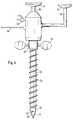
- the trocar shown in Figure 1has a hollow cylindrical shaft 10 made of steel, in the distal front end of which a tip 12 described below is inserted.
- the eyepiece 16provided with an eyecup 14, of an optical system, which is described below, is arranged coaxially in the shaft 10.
- a light guide 18 of a lighting unit described belowis inserted laterally into the rear end of the shaft 10.
- an insufflation valve 20is arranged at the rear end of the shaft 10, through which, in a manner known per se, e.g. CO2 gas can be supplied to outlet openings, not shown, at the front distal shaft end.
- a sleeve 22is rotatably but axially immovable.
- the sleeve 22has a blunt screw thread 24 on its outer jacket.
- the sleeve 22can be driven to rotate relative to the shaft 10 by means of a ratchet 28 provided with grip knobs 26.
- An electromotive drive of the sleeve 22is also possible. If the sleeve 22 is rotated with the trocar inserted, the screw thread 24 causes the trocar to be axially advanced, whereby the trocar itself does not rotate. With the aid of the sleeve 22 provided with the screw thread 24, the trocar can be moved slowly without exerting any axial pressure on the operator and be advanced in the tissue with sensitivity.
- a tip 12is inserted into the distal end of the hollow shaft 10, e.g. screwed or soldered.
- An optic 32is inserted into a bore leading axially in the center of the tip 12.
- the optic 32is guided axially through the entire shaft 10 and ends at the proximal rear end in the eyepiece 16.
- the distal front end of the optic 32is cemented or glued into the bore of the tip 12.
- the optics 32is a wide-angle optics known per se, as is used for example for endoscopes.
- An optical fiber opticis preferably used.
- a lighting unit 38 in the form of a light guideis inserted into each of these bores.
- the light guides of the lighting units 38are guided through the shaft 10.
- the lighting units 38are supplied with light via the light guide 18 and a branch.
- the tip 12consists of an end flange 40 made of steel, which is inserted into the distal end of the hollow shaft 10.
- An optical window 34 in the form of a hollow cone made of glass, quartz glass, plexiglass or diamondis placed on the front of the end flange 40 and e.g. fixed by gluing or cementing.
- the end flange 40has the central axially continuous Hole in which the optics 32 is inserted. Furthermore, the four bores arranged around the optics for the lighting units 38 are provided in the end flange 40. The optics 32 and the lighting units 38 end on the front end face of the end flange 40. The lighting units 38 thus illuminate the entire cone of the window 34 and the optics 32 enable the tissue penetrated by the tip 12 to be observed over the entire cone surface of the window 34.
- the inner surface of the window 34can optionally be anti-reflective.
- direct lightingcan also be effected if a lighting unit, e.g. is integrated in the form of a light-guiding optical fiber, which is also supplied with light via the light guide 18.
- a lighting unite.g. is integrated in the form of a light-guiding optical fiber, which is also supplied with light via the light guide 18.
- the window 34can form a sharp tip that allows easy penetration of the tissue with the trocar. Since the optic 32 does not emerge in the end face of the tip 12 but in the end face 40 of the end flange 40 which forms the base of the tip 12, an optic 32 with a larger diameter can also be used, e.g. a conventional rod lens system (so-called Hopkins optics), which has an improved light output. Here, too, the lighting unit 38 can be integrated into the optics 32.
- the optic 32is of course also a wide-angle optic in this case.
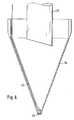
- FIGS. 4, 5 and 6A further embodiment is shown in FIGS. 4, 5 and 6.
- the optical window 34is more transparent than placed on an end flange 40 of the tip 12 Hollow cone formed, as described in connection with Figures 2 and 3.
- the first optic 32is inserted axially in the center, which preferably permits observation through the entire conical surface of the window 34 as a rod lens system.
- a second optic 42is guided through the shaft 10 to the tip 12.
- the second optics 42is eccentrically guided to the first optics 32 through the end flange 40 and runs inside the hollow-cone window 34 into the apex of the tip 12.
- the second optics 42exits through the end face of the conical window 34 .
- the end facecan be formed by the distal foremost part of the second optics 42.
- a window 44can be provided in the end face in front of the second optics 42. This window 44 can be machined as a ground surface from the material of the window 34, as shown in Figure 5, or can be inserted into the window 34 and e.g.
- the second optics 42preferably contain an integrated lighting unit.
- the second optics 42is preferably designed as a thin light guide optics with a diameter of 0.2 to 0.8 mm.
- the second optics 42are preferably flexible so that they can be guided along the inside of the window 34.
- the proximal rear end of the second optics 42is led laterally out of the shaft 10 and equipped with a second eyepiece 46 so that the surgeon can observe binocularly via both optics 32 and 42.
- the second optics 42which is guided inside the conical window 34 into the apex of the tip 12, is impeded the view of the first optics 32 practically not, since the second optics 42 has a small diameter and preferably consists of transparent glass fibers.
- FIGS. 4 to 6provides the surgeon with optimal information when piercing the trocar. Via the first optics 32 and the conical window 34, he can observe the tissue structures passed through when penetrating the tissue in order to obtain the necessary information about the position of the tip and the speed of the feed. Via the second optics 42, he has a view of the tissue structures lying in front of the tip 12 immediately before they are penetrated.
- penetration of the peritoneumcan take place under sight, the still intact semitransparent peritoneum immediately in front of the tip 12 allowing an insight into the abdominal cavity via the second optic, so that when the peritoneum penetrates, an injury to vessels of the peritoneum and the underlying omentum majus and the bowels can be avoided.
- a gripping memberis additionally arranged at the tip of the trocar, which serves to hold the body tissue against the pressure of the trocar tip during penetration.
- the body tissuee.g. the peritoneum, cannot escape from the trocar tip and be arched inwards into the abdominal cavity.
- the gripping memberconsists of a helix 48 which is rotatably mounted on the outside on the conical window 34 and which is manufactured, for example, from a wire and is adapted to the conical shape of the window 34.
- the helix 48is bent at its rear end into an axially parallel connecting piece 50, which is formed at its end into a ring, not visible in the drawing, which is rotatably mounted in a circumferential groove of the shaft 10 of the trocar.
- the helix 48is thus rotatably mounted on the conical window 34 and held axially.
- the screw thread 24 of the sleeve 22extends beyond the front distal end of the sleeve and acts as a driving tip 52 on the rear end of the helix 48 in order to take it with the driven rotation of the sleeve 22.
- the sleeve 22For penetrating the body tissue, e.g. the abdominal wall of the patient, the sleeve 22 is driven in rotation, whereby it also rotates the helix 48 on the conical window 34 via the driver tip 52. Due to the rotating helix 48 and the screw thread 24 adjoining it, the trocar bores into the tissue in the manner of a corkscrew without it being able to avoid the penetrating trocar tip. As soon as the tissue is penetrated and the trocar tip e.g. located in the abdominal cavity, the trocar can be pulled out of the sleeve 22 together with the helix 48 held axially on its tip. The sleeve 22 can then be used to insert surgical instruments or the like.
Landscapes
- Health & Medical Sciences (AREA)
- Life Sciences & Earth Sciences (AREA)
- Surgery (AREA)
- Animal Behavior & Ethology (AREA)
- Public Health (AREA)
- Engineering & Computer Science (AREA)
- Biomedical Technology (AREA)
- Heart & Thoracic Surgery (AREA)
- Medical Informatics (AREA)
- Molecular Biology (AREA)
- Pathology (AREA)
- General Health & Medical Sciences (AREA)
- Nuclear Medicine, Radiotherapy & Molecular Imaging (AREA)
- Veterinary Medicine (AREA)
- Physics & Mathematics (AREA)
- Optics & Photonics (AREA)
- Biophysics (AREA)
- Radiology & Medical Imaging (AREA)
- Endoscopes (AREA)
- Materials For Medical Uses (AREA)
- Surgical Instruments (AREA)
- Instruments For Viewing The Inside Of Hollow Bodies (AREA)
- Treatment Of Fiber Materials (AREA)
Abstract
Description
Translated fromGermanDie Erfindung betrifft ein Instrument zum Penetrieren von Körpergewebe gemäß dem Oberbegriff des Patentanspruchs 1.The invention relates to an instrument for penetrating body tissue according to the preamble of patent claim 1.
Instrumente dieser Gattung dienen insbesondere als Trokare dazu, einen künstlichen Zugang zu Körperhöhlen oder Organen zu schaffen, die keine natürliche Verbindung nach außen aufweisen. Das Instrument weist eine Spitze auf, die dazu dient, das Körpergewebe zu durchbohren und die Perforationsöffnung auf den Durchmesser des Schafts aufzuweiten. Bei Verwendung als Trokar wird dabei eine den Schaft umschließende Hülse zusammen mit dem Trokar in die Perforationsöffnung vorgeschoben und stellt nach dem Abziehen des Trokars den künstlichen Zugang zu der Körperhöhle dar, durch welchen Endoskope, Instrumente und dergleichen in das Körperinnere eingeführt werden können.Instruments of this type serve in particular as trocars to provide artificial access to body cavities or organs that have no natural connection to the outside. The instrument has a tip which is used to pierce the body tissue and to widen the perforation opening to the diameter of the shaft. When used as a trocar, a sleeve enclosing the shaft is pushed into the perforation opening together with the trocar and, after the trocar has been removed, represents the artificial access to the body cavity through which endoscopes, instruments and the like can be introduced into the interior of the body.
Das Einstechen des Trokars bringt auch bei günstiger Wahl des Einstichortes die Gefahr mit sich, daß Blutgefäße im Unterhautfettgewebe, in der Muskelfascie und im Peritoneum (Bauchfell), also Gefäße der Bauchdecke, verletzt werden. Weiter besteht nach dem Penetrieren der Bauchdecke die Gefahr, daß Gefäße des Abdominalraumes (Bauchhöhle) und Organe des Bauchraumes, wie Dickdarm, Dünndarm, Omentum Majus (großes Netz) und retroperitoneal liegende Gefäße und Strukturen verletzt werden können. Besonders verletzungsgefährdet ist der Dünndarm und das Omentum Majus, wenn Adhäsionen und Verwachsungen mit der vorderen Bauchwand bestehen, so daß beim Penetrieren der Bauchwand gleichzeitig die mit dieser verwachsenen Strukturen durchbohrt werden können, ehe der Trokar in die freie Bauchhöhle gelangt. Um die Verletzungsgefahr insbesondere des Darmes und des Omentum Majus zu reduzieren, kann zunächst unter Anheben der Bauchdecke eine Hohlnadel durch die Bauchdecke geführt werden, um Gas in die Bauchhöhle einzuleiten und die Bauchdecke von dem darunterliegenden Omentum Majus und Darm für das anschließende Einstechen des Trokars zu distanzieren. Auch hierbei bleibt jedoch beim Einstechen der Kohlnadel und des Trokars ein Restrisiko der Verletzung.Piercing the trocar, even with a favorable choice of the puncture site, entails the risk that blood vessels in the subcutaneous fatty tissue, in the muscle fascia and in the peritoneum (peritoneum), i.e. vessels of the abdominal wall, are injured. After penetration of the abdominal wall, there is also the risk that vessels of the abdominal cavity (abdominal cavity) and organs of the abdominal cavity, such as the large intestine, small intestine, omentum majus (large network) and retroperitoneal lying vessels and structures can be injured. The small intestine and the omentum are particularly at risk of injury if there are adhesions and adhesions to the anterior abdominal wall, so that when the abdominal wall is penetrated, the structures that have grown together can be pierced before the trocar enters the free abdominal cavity. In order to reduce the risk of injury, in particular of the intestine and omentum majus, a hollow needle can first be passed through the abdominal wall while lifting the abdominal wall to introduce gas into the abdominal cavity and the abdominal wall from the underlying omentum majus and intestine for the subsequent piercing of the trocar distance. Here too, however, there is a residual risk of injury when the cabbage needle and trocar are inserted.
Ein aus DE 29 22 239 C2 bekanntes Instrument weist ein Außenrohr auf, das an seinem distalen vorderen Ende abgeschrägt ist, um eine Einstechspitze zu bilden. In dem Außenrohr sind zwei Lichtleiterbündel zur Spitze geführt, deren vordere Endflächen in der Ebene der abgeschrägten Stirnfläche des Außenrohres liegen. Das Licht einer Lichtquelle wird durch ein Lichtleiterbündel geführt und tritt an der distalen Spitze aus. Das zweite Lichtleiterbündel empfängt den reflektierten Anteil dieses austretenden Lichtes und leitet diesen zu einem lichtempfindlichen Element. Die gemessene Intensität des reflektierten Lichts stellt eine Information über die anatomische Struktur vor der Spitze dar. Die Änderung der Intensität des reflektierenden Lichts läßt erkennen, wenn sich die Spitze des Instruments im freien Bauchraum einem Organ nähert. Beim Durchdringen aufeinanderfolgender Gewebeschichten der Bauchdecke oder beim Eindringen der Spitze in durch Adhäsionen und Verwachsungen mit der Bauchwand verbundene Organe ändert sich jedoch das Reflexionsvermögen der Gewebestrukturen vor der Spitze praktisch nicht, so daß eine Kontrolle des Eindringens der Spitze nicht möglich ist. Die Abschrägung des Außenrohres ergibt eine Einstechspitze, die an dem Mantel des Außenrohres seitlich neben der Austrittsfläche der Lichtleiterbündel angeordnet ist und diese überragt. Die Einstechspitze beschränkt dadurch das über das optische System kontrollierbare Sichtfeld.An instrument known from DE 29 22 239 C2 has an outer tube which is chamfered at its distal front end in order to form an insertion tip. In the outer tube, two light guide bundles are guided to the tip, the front end faces of which lie in the plane of the beveled end face of the outer tube. The light from a light source is guided through an optical fiber bundle and emerges at the distal tip. The second light guide bundle receives the reflected portion of this emerging light and guides it to a light-sensitive element. The measured intensity of the reflected light represents information about the anatomical structure in front of the tip. The change in the intensity of the reflecting light reveals when the tip of the instrument approaches an organ in the free abdominal cavity. However, when penetrating successive layers of tissue in the abdominal wall or penetrating the tip into organs connected to the abdominal wall by adhesions and adhesions, the reflectivity of the tissue structures in front of the tip practically does not change, so that it is not possible to control the penetration of the tip. The beveling of the outer tube results in a puncture tip which is arranged on the jacket of the outer tube laterally next to the exit surface of the light guide bundle and projects beyond it. The piercing tip thus limits the field of view that can be controlled via the optical system.
Aus DE-AS 16 16 107 ist ein als Mikroskop dienendes faseroptisches System bekannt, das in einer Einstechnadel angeordnet ist. Das das optische System umschließende Außenrohr der Nadel ist an dem distalen Ende abgeschrägt, um die Einstechspitze zu bilden. Über das optische System kann das Gewebe vor der Spitze der Nadel mikroskopisch beobachtet werden. Die Nadel ist nicht als Trokar verwendbar, da ihr geringer Durchmesser nicht zu einer Aufweitung des Perforationsloches führt. Die durch die Abschrägung des Außenrohres erzeugte Einstechspitze erzeugt einen das Sichtfeld einschränkenden toten Winkel.From DE-AS 16 16 107 a fiber optic system serving as a microscope is known, which is arranged in a puncture needle. The outer tube of the needle enclosing the optical system is chamfered at the distal end to form the piercing tip. The tissue in front of the tip of the needle can be observed microscopically via the optical system will. The needle cannot be used as a trocar because its small diameter does not cause the perforation hole to widen. The penetration tip created by the beveling of the outer tube creates a blind spot that restricts the field of vision.
Aus EP 0 369 937 A1, EP 0 369 936 A1 und EP 0 347 140 A1 sind Endoskope bekannt, die ein Außenrohr aufweisen, in welchem faseroptische Systeme zur Spitze geführt sind. Diese Endoskope ermöglichen eine Beobachtung in Richtung der an der Spitze austretenden Lichtleiterfasern. Die Endoskope sind nicht zum Penetrieren von Gewebe geeignet.Endoscopes are known from EP 0 369 937 A1, EP 0 369 936 A1 and EP 0 347 140 A1 which have an outer tube in which fiber-optical systems are guided to the tip. These endoscopes enable observation in the direction of the optical fibers emerging at the tip. The endoscopes are not suitable for penetrating tissue.
Aus DE-OS 22 18 901 ist ein massiver Trokar bekannt, dessen Trokarhülse an ihrem proximalen Ende eine äußere Schraubenwindung aufweist. Die Schraubenwindung dient dazu, die gesetzte Trokarhülse zuverlässiger gegen eine axiale Verschiebung in der durch den Trokar erzeugten Perforationsöffnung festzulegen.A solid trocar is known from DE-OS 22 18 901, the trocar sleeve of which has an outer screw turn at its proximal end. The screw turn serves to fix the inserted trocar sleeve more reliably against axial displacement in the perforation opening created by the trocar.
Der Erfindung liegt die Aufgabe zugrunde, ein Instrument zum Penetrieren von Körpergewebe zur Verfügung zu stellen, das durch eine verbesserte optische Kontrolle beim Einstechen das Risiko von Verletzungen von Gefäßen, Organen und dergleichen weitestmöglich reduziert.The invention is based on the object of providing an instrument for penetrating body tissue which, as far as possible, reduces the risk of injuries to vessels, organs and the like by means of improved optical control during piercing.
Diese Aufgabe wird bei einem gattungsgemäßen Instrument erfindungsgemäß durch die im kennzeichnenen Teil des Patentanspruchs 1 angegebenen Merkmale gelöst.This object is achieved according to the invention in a generic instrument by the features specified in the characterizing part of patent claim 1.
Vorteilhafte Ausführungsformen der Erfindung sind in den Unteransprüchen angegeben.Advantageous embodiments of the invention are specified in the subclaims.
Das erfindungsgemäße Instrument weist einen hohlen Schaft auf. Die Spitze oder zumindest der distale Endteil der Spitze ist als Fenster aus einem geeigneten durchsichtigen Material ausgebildet, z.B. aus Glas, Quarzglas, Plexiglas oder dergleichen. Durch den hohlen Schaft ist eine Optik zu der Spitze geführt, z.B. eine Optik mit Glasfaserlichtleiter, wie sie in Endoskopen verwendet wird. Weiter ist in dem hohlen Schaft eine Beleuchtungseinheit zur Spitze geführt. Die Beleuchtungseinheit kann in die Optik integriert werden, indem zur Beleuchtung dienende Lichtleiterfasern in den Strang der Optik eingesetzt sind. Ebenso ist es möglich, die Beleuchtung getrennt von der Optik durch den Schaft in die Spitze zu führen oder auch in die Optik integrierte Beleuchtungseinheiten mit zusätzlichen getrennt geführten Beleuchtungseinheiten zu kombinieren. Die Optik endet in einem axialen Abstand hinter dem Scheitelpunkt der Spitze, so daß durch die Optik die gesamte Mantelfläche des kegelförmigen Fensters beleuchtet und beobachtet werden kann. Der Operateur hat somit beim Vorschub des Instruments Sicht auf die vor der Spitze des Instruments liegenden Strukturen, die penetriert werden. Der Operateur kann also z.B. Blutgefäße erkennen, bevor diese von der Spitze des Instruments getroffen werden, und diesen ausweichen. Insbesondere kann auch der wichtige Schritt des Durchdringens des Peritoneums unter Sicht erfolgen. Das semitransparene Peritoneum läßt bereits vor der vollständigen Durchdringung einen Einblick in den Abdominalraum zu, so daß das darunter liegende Omentum Majus, die Därme sowie Gefäßstrukturen des Peritoneums erkennbar sind und deren Verletzung vermieden werden kann. Außerdem kann der Operateur beim Vorschub des Instruments die seitlich an der Mantelfläche des Fensters vorbeiwandernden, von der Spitze durchdrungenen Strukturen beobachten und bekommt dadurch ein Gefühl für das Eindringen der Spitze und für die Vorschubgeschwindigkeit.The instrument according to the invention has a hollow shaft on. The tip or at least the distal end part of the tip is formed as a window from a suitable transparent material, for example from glass, quartz glass, plexiglass or the like. An optic is guided through the hollow shaft to the tip, for example an optic with glass fiber light guide, as is used in endoscopes. Furthermore, a lighting unit is guided to the tip in the hollow shaft. The lighting unit can be integrated into the optics by inserting optical fibers used for lighting in the strand of the optics. It is also possible to guide the lighting separately from the optics through the shaft into the tip or to combine lighting units integrated in the optics with additional separately guided lighting units. The optics end at an axial distance behind the apex of the tip, so that the entire surface area of the conical window can be illuminated and observed through the optics. When the instrument is advanced, the surgeon thus has a view of the structures lying in front of the tip of the instrument that are being penetrated. For example, the surgeon can recognize blood vessels before they hit the tip of the instrument and dodge them. In particular, the important step of penetrating the peritoneum can also be carried out under sight. The semitransparent peritoneum allows an insight into the abdominal space even before it is completely penetrated, so that the underlying omentum majus, the intestines and vascular structures of the peritoneum are recognizable and their injury can be avoided. In addition, when the instrument is advanced, the surgeon can observe the structures passing through the lateral surface of the window and penetrated by the tip, and thereby get a feeling for the penetration of the tip and for the rate of advance.
Das Fenster dient aufgrund seiner Kegelform als Spitze, die sowohl das Penetrieren des Gewebes als auch das Aufweiten des Perforationsloches bewirkt. Die spezielle Gestalt des kegelförmigen Fensters ist dabei von geringerer Bedeutung. Bevorzugt wird ein gerader Kreiskegel, da dieser am einfachsten herzustellen ist und die geringste optische Verzerrung bei der Beobachtung liefert. Grundsätzlich sind jedoch auch andere Kegelformen möglich, z.B. mit polygonaler Grundfläche und mit leicht balliger oder leicht eingezogener Mantellinie.Due to its conical shape, the window serves as a tip, which causes both the penetration of the fabric and the widening of the perforation hole. The special shape of the conical window is of less importance. A straight circular cone is preferred because it is the easiest to manufacture and provides the least optical distortion during observation. In principle, however, other cone shapes are also possible, e.g. with a polygonal base and with a slightly spherical or slightly drawn surface line.
Da die Beleuchtungseinheit innerhalb des die Spitze bildenden Fensters angeordnet ist und die Beleuchtung durch dieses Fenster erfolgt, kann es vorteilhaft sein, die Innenfläche des Fensters zu entspiegeln. Die Kegelform des Fensters ergibt bei hohler Spitze jedoch zwangsläufig eine Schrägstellung der inneren Fensterflächen gegenüber der optischen Achse der Beleuchtung und der Optik, so daß störende Reflexionen ohnehin gering sind.Since the lighting unit is arranged within the window forming the tip and the lighting takes place through this window, it can be advantageous to antireflect the inner surface of the window. The cone shape of the window, however, inevitably results in a slanted position of the inner window surfaces with respect to the optical axis of the lighting and the optics, so that disturbing reflections are small anyway.
In einer vorteilhaften Ausführungsform kann die Beobachtung des vor der Spitze des Instruments liegenden Bereiches noch zusätzlich verbessert werden, so daß sich für den Operateur eine Kombination des statischen Bildes des vor der Spitze des Instruments liegenden Bereichs mit dem dynamischen Bild des Vordringens der Spitze ergibt. In dieser Ausführung ist in die das Fenster bildende Spitze zusätzlich zu der die gesamte Mantelfläche des Fensters betrachtenden Optik eine zweite Optik geführt, die als dünne flexible Glasfaser-Optik ausgebildet ist. Diese zweite Optik ist seitlich an der ersten Optik vorbei in die das Fenster bildende Spitze geführt und endet in der Stirnfläche der das Fenster bildenden Spitze. Diese zweite Optik mit möglichst geringem Durchmesser ergibt somit die Sicht auf den Bereich vor der Spitze, während die erste Optik die Sicht auf die an der Mantelfläche des Fensters anliegenden durchdrungenen Strukturen ermöglicht. Der kleine Durchmesser der zweiten Faseroptik behindert die Beobachtung durch die erste Optik praktisch nicht.In an advantageous embodiment, the observation of the area in front of the tip of the instrument can be additionally improved, so that the operator has a combination of the static image of the area in front of the tip of the instrument with the dynamic image of the tip advancing. In this embodiment, in addition to the optics that look at the entire lateral surface of the window, a second optic, which is designed as a thin, flexible glass fiber optic, is guided into the tip forming the window. This second optic is guided laterally past the first optic into the tip forming the window and ends in the end face of the tip forming the window. This second optic with the smallest possible diameter thus provides a view of the area in front of the tip, while the first optics allow a view of the penetrated structures lying against the outer surface of the window. The small diameter of the second fiber optic practically does not hinder the observation by the first optic.
In dieser Ausführungsform kann der Operateur durch zwei Okulare sowohl das Vordringen der Spitze des Instruments beobachten, um ein Gefühl für Vorschubweg und Vorschubgeschwindigkeit zu bekommen, als auch die vor der Spitze liegenden Strukturen beobachten, um Verletzungen von Gefäßen, von Organen, des Darmes oder des Omentum Majus zu vermeiden.In this embodiment, the operator can use two eyepieces to observe the advancement of the tip of the instrument in order to get a feeling for the feed path and feed rate, and to observe the structures in front of the tip in order to injure vessels, organs, the intestine or the Avoid omentum majus.
In allen Fällen sind die Optiken vorzugsweise als Weitwinkeloptik (fish eye-Optik) ausgebildet, um dem Operateur ein möglichst großes Sichtfeld zu bieten und eine Beobachtung durch die gesamte Mantelfläche des kegelförmigen Fensters zu ermöglichen.In all cases, the optics are preferably designed as wide-angle optics (fish eye optics) in order to offer the surgeon as large a field of vision as possible and to enable observation through the entire lateral surface of the conical window.
Ist das Instrument als Trokar mit einer Trokar-Hülse ausgebildet, so kann bei dem Einstechen des Trokars unter Sicht die Möglichkeit eines Ausweichens verletzungsgefährdeter Strukturen optimal ausgenützt werden, wenn die Hülse ein Außengewinde aufweist. Die Hülse ist axial unverschieblich jedoch drehbar auf dem Trokar gelagert. Durch Drehen der Hülse greift deren Außengewinde in das Gewebe und bewirkt den Vorschub des Trokars. Der Trokar mit seiner Optik dreht sich dabei nicht. Der Vorschub über die mit Gewinde versehene Hülse ermöglicht ein gleichmäßiges ruckfreies Eindringen der Trokarspitze, ohne daß der Operateur einen axialen Druck auf den Trokar ausüben muß. Dies begünstigt ein feinfühliges Führen der Trokarspitze im Bereich verletzungsgefährdeter Strukturen.If the instrument is designed as a trocar with a trocar sleeve, when piercing the trocar, the possibility of evading structures at risk of injury can be optimally exploited if the sleeve has an external thread. The sleeve is axially immovable but rotatably mounted on the trocar. By turning the sleeve, the external thread engages in the tissue and causes the trocar to advance. The trocar with its optics does not turn. The feed over the threaded sleeve enables the trocar tip to be penetrated evenly without jerks, without the operator having to exert an axial pressure on the trocar. This promotes sensitive guidance of the trocar tip in the area of structures at risk of injury.
Um die Hülse ohne größeren Kraftaufwand drehen zu können, kann diese über eine Ratsche manuell angetrieben werden. Ebenso ist ein Antrieb über einen Elektromotor mit entsprechender Untersetzung möglich.In order to be able to turn the sleeve without great effort, it can be driven manually using a ratchet. A drive via an electric motor with appropriate gear reduction is also possible.
Das erfindungsgemäße Instrument wird vorzugsweise als Trokar zum Penetrieren der Bauchdecke und zum Einführen einer Trokar-Hülse in die Perforationsöffnung verwendet. Weiter kann das erfindungsgemäße Instrument als Perforationsnadel mit dünnem Schaft verwendet werden, um die Bauchdecke zu penetrieren und Gas in den Abdominalraum einzuleiten, so daß die Bauchdecke vor dem Einstechen des Trokars von den inneren Organen abgehoben wird. Schließlich kann das erfindungsgemäße Instrument mit einem sehr feinen Schaft in der pränatalen Diagnostik verwendet werden, um die Fruchtblase zur Entnahme einer Fruchtwasserprobe anzustechen, wobei die Sicht durch die Spitze des Instruments zuverlässig eine Schädigung des Fetus ausschließt.The instrument according to the invention is preferably used as a trocar for penetrating the abdominal wall and for inserting a trocar sleeve into the perforation opening. Furthermore, the instrument according to the invention can be used as a perforation needle with a thin shaft in order to penetrate the abdominal wall and to introduce gas into the abdominal space, so that the abdominal wall is lifted off the internal organs before the trocar is inserted. Finally, the instrument according to the invention with a very fine shaft can be used in prenatal diagnostics to pierce the amniotic sac to take an amniotic fluid sample, the view through the tip of the instrument reliably precluding damage to the fetus.
Im folgenden wird die Erfindung anhand von in der Zeichnung dargestellten Ausführungsbeispielen näher erläutert. Es zeigen :
- Figur 1
- eine Seitenansicht eines als Trokar ausgebildeten Insruments,
- Figur 2
- einen Axialschnitt der Spitze des Trokars,
- Figur 3
- eine Stirnansicht der Spitze von hinten,
- Figur 4
- eine Seitenansicht des Trokars in einer weiteren Ausführungsform,
- Figur 5
- einen Axialschnitt der Spitze des Trokars der Figur 4,
- Figur 6
- einen Figur 5 entsprechenden Axialschnitt einer abgewandelten Ausführungsform und
- Figur 7
- eine Seitenansicht der Spitze des Trokars in einer weiteren Ausführungsform.
- Figure 1
- 2 shows a side view of an instrument designed as a trocar,
- Figure 2
- an axial section of the tip of the trocar,
- Figure 3
- a front view of the tip from behind,
- Figure 4
- a side view of the trocar in a further embodiment,
- Figure 5
- 3 shows an axial section of the tip of the trocar of FIG. 4,
- Figure 6
- an axial section corresponding to Figure 5 of a modified embodiment and
- Figure 7
- a side view of the tip of the trocar in a further embodiment.
Der in Figur 1 dargestellte Trokar weist einen hohlen zylindrischen Schaft 10 aus Stahl auf, in dessen distales vorderes Ende eine nachfolgend beschriebene Spitze 12 eingesetzt ist. Am proximalen hinteren Ende des Schaftes 10 sitzt das mit einer Augenmuschel 14 versehene Okular 16 einer nachfolgend beschriebenen koaxial in dem Schaft 10 angeordneten Optik. Weiter ist seitlich in das hintere Ende des Schaftes 10 ein Lichtleiter 18 einer nachfolgend beschriebenen Beleuchtungseinheit eingeführt. Schließlich ist am hinteren Ende des Schaftes 10 ein Insufflationshahn 20 angeordnet, durch welchen in an sich bekannter Weise z.B. CO₂-Gas zu nicht dargestellten Austrittsöffnungen am vorderen distalen Schaftende zugeführt werden kann.The trocar shown in Figure 1 has a hollow
Auf den Schaft 10 ist eine Hülse 22 drehbar aber axial unverschieblich gelagert. Die Hülse 22 weist an ihrem Außenmantel ein stumpfes Schraubengewinde 24 auf. Die Hülse 22 kann gegenüber dem Schaft 10 über eine mit Griffknebeln 26 versehene Ratsche 28 drehend angetrieben werden. Ebenso ist ein elektromotorischer Antrieb der Hülse 22 möglich. Wird die Hülse 22 bei eingestochenem Trokar gedreht, so bewirkt das Schraubengewinde 24 einen axialen Vorschub des Trokars, wobei dieser selbst sich nicht dreht. Mit Hilfe der mit dem Schraubengewinde 24 versehenen Hülse 22 kann der Trokar ohne Ausübung eines axialen Druckes durch den Operateur langsam und feinfühlig in dem Gewebe vorgeschoben werden.On the
Wie aus den Figuren 2 und 3 zu ersehen ist, ist in das distale Ende des hohlen Schaftes 10 eine Spitze 12 eingesetzt, z.B. eingeschraubt oder eingelötet.As can be seen from Figures 2 and 3, a
In eine axial mittig in die Spitze 12 führende Bohrung ist eine Optik 32 eingesetzt. Die Optik 32 ist axial durch den gesamten Schaft 10 hindurchgeführt und endet am proximalen hinteren Ende in dem Okular 16. Das distal vordere Ende der Optik 32 ist in die Bohrung der Spitze 12 eingekittet oder eingeklebt.An optic 32 is inserted into a bore leading axially in the center of the
Die Optik 32 ist eine an sich bekannte Weitwinkel-Optik, wie sie beispielsweise für Endoskope verwendet wird. Vorzugsweise wird eine Lichtleiter-Optik verwendet.The
Parallel zu der die Optik 32 aufnehmenden mittigen Bohrung sind vier weitere Bohrungen in der Spitze 12 vorgesehen, die in gleichem Abstand um die mittige Bohrung angeordnet sind. In diese Bohrungen ist jeweils eine Beleuchtungseinheit 38 in Form eines Lichtleiters eingesetzt. Die Lichtleiter der Beleuchtungseinheiten 38 sind durch den Schaft 10 geführt. Den Beleuchtungseinheiten 38 wird über den Lichtleiter 18 und eine Verzweigung Licht zugeführt.Parallel to the central bore receiving the
Die Spitze 12 besteht aus einem Endflansch 40 aus Stahl, der in das distale Ende des hohlen Schaftes 10 eingesetzt ist. Vorne auf den Endflansch 40 ist ein optisches Fenster 34 in Form eines Hohlkegels aus Glas, Quarzglas, Plexiglas oder Diamant aufgesetzt und z.B. durch Verkleben oder Verkitten befestigt.The
Der Endflansch 40 weist die mittige axial durchgehende Bohrung auf, in welche die Optik 32 eingesetzt wird. Weiter sind in dem Endflansch 40 die vier rings um die Optik angeordnete Bohrungen für die Beleuchtungseinheiten 38 vorgesehen. Die Optik 32 und die Beleuchtungseinheiten 38 enden an der vorderen Stirnfläche des Endflansches 40. Die Beleuchtungseinheiten 38 leuchten somit den gesamten Kegel des Fensters 34 aus und die Optik 32 ermöglicht die Beobachtung des von der Spitze 12 durchdrungenen Gewebes über die gesamte Kegelfläche des Fensters 34. Die Innenfläche des Fensters 34 kann gegebenenfalls entspiegelt sein.The
Zusätzlich zu oder anstelle dieser indirekten Beleuchtung kann auch eine direkte Beleuchtung bewirkt werden, wenn in die Optik 32 eine Beleuchtungseinheit z.B. in Form einer lichtführenden Lichtleiterfaser integriert ist, der ebenfalls über den Lichtleiter 18 Licht zugeführt wird.In addition to or instead of this indirect lighting, direct lighting can also be effected if a lighting unit, e.g. is integrated in the form of a light-guiding optical fiber, which is also supplied with light via the
Das Fenster 34 kann eine scharfe Spitze bilden, die ein leichtes Penetrieren des Gewebes mit dem Trokar ermöglicht. Da die Optik 32 nicht in der Stirnfläche der Spitze 12 austritt sondern in der die Basis der Spitze 12 bildenden Stirnfläche des Endflansches 40, kann auch eine Optik 32 mit größerem Durchmesser verwendet werden, z.B. ein herkömmliches Stablinsensystem (sogenannte Hopkins-Optik), die eine verbesserte Lichtausbeute aufweist. Auch hier kann die Beleuchtungseinheit 38 in die Optik 32 integriert sein. Die Optik 32 ist auch in diesem Fall selbstverständlich eine Weitwinkeloptik.The
In den Figuren 4, 5 und 6 ist eine weitere Ausführungsform dargestellt.A further embodiment is shown in FIGS. 4, 5 and 6.
In dieser Ausführungsform ist das optische Fenster 34 als auf einen Endflansch 40 der Spitze 12 aufgesetzter durchsichtiger Hohlkegel ausgebildet, wie dies in Verbindung mit den Figuren 2 und 3 beschrieben ist. Axial mittig ist die erste Optik 32 eingesetzt, die vorzugsweise als Stablinsensystem die Beobachtung durch die gesamte Kegelmantelfläche des Fensters 34 erlaubt.In this embodiment, the
Zusätzlich zu dieser ersten Optik 32 ist eine zweite Optik 42 durch den Schaft 10 zur Spitze 12 geführt. Die zweite Optik 42 ist exzentrisch zu der ersten Optik 32 durch den Endflansch 40 geführt und läuft innen an dem hohlkegeligen Fenster 34 in den Scheitelpunkt der Spitze 12. In dem Scheitelpunkt der Spitze 12 tritt die zweite Optik 42 durch die Stirnfläche des kegelförmigen Fensters 34 aus. Die Stirnfläche kann dabei durch das distal vorderste Teil der zweiten Optik 42 gebildet werden. Um die zweite Optik 42 vor Druck und Verschmutzung zu schützen, kann vor der zweiten Optik 42 ein Fenster 44 in der Stirnfläche vorgesehen sein. Dieses Fenster 44 kann als eine geschliffene Fläche aus dem Material des Fensters 34 ausgearbeitet sein, wie dies Figur 5 zeigt, oder kann in das Fenster 34 eingesetzt und z.B. durch eine Schulter axial abestützt sein, wie dies Figur 6 zeigt. Die zweite Optik 42 enthält vorzugsweise eine integrierte Beleuchtungseinheit. Die zweite Optik 42 ist vorzugsweise als dünne Lichtleiteroptik mit einem Durchmesser von 0.2 bis 0.8 mm ausgebildet. Vorzugsweise ist die zweite Optik 42 flexibel, so daß sie innen an dem Fenster 34 entlanggeführt werden kann. Das proximale hintere Ende der zweiten Optik 42 ist seitlich aus dem Schaft 10 herausgeführt und mit einem zweiten Okular 46 ausgestattet, so daß der Operateur binokular über beide Optiken 32 und 42 beobachten kann.In addition to this
Die innerhalb des kegelförmigen Fensters 34 in den Scheitelpunkt der Spitze 12 geführte zweite Optik 42 behindert die Sicht der ersten Optik 32 praktisch nicht, da die zweite Optik 42 einen geringen Durchmesser hat und vorzugsweise aus durchsichtigen Glasfasern besteht.The
Die Ausführungsform der Figuren 4 bis 6 bietet dem Operateur beim Einstechen des Trokars eine optimale Information. Über die erste Optik 32 und das kegelförmige Fenster 34 kann er beim Penetrieren des Gewebes die jeweils durchfahrenen Gewebsstrukturen beobachten, um die erforderlichen Informationen über die Position der Spitze und die Geschwindigkeit des Vorschubes zu erhalten. Über die zweite Optik 42 hat er die Sicht auf die vor der Spitze 12 liegenden Gewebsstrukturen unmittelbar vor deren Penetrierung. Insbesondere kann das Durchdringen des Peritoneums unter Sicht erfolgen, wobei das noch intakte semitransparente Peritoneum unmittelbar vor der Spitze 12 über die zweite Optik einen Einblick in die Bauchhöhle zuläßt, so daß beim Durchdringen des Peritoneums eine Verletzung von Gefäßen des Peritoneums und des darunterliegenden Omentum Majus und der Därme vermieden werden kann.The embodiment of FIGS. 4 to 6 provides the surgeon with optimal information when piercing the trocar. Via the
In einer in Figur 7 dargestellten weiteren Ausführungsform ist an der Spitze des Trokars zusätzlich ein Greifglied angeordnet, welches dazu dient, das Körpergewebe beim Penetrieren gegen den Druck der Trokarspitze festzuhalten. Das Körpergewebe, z.B. das Peritoneum, kann dadurch nicht der Trokarspitze ausweichen und nach innen in die Abdominalhöhle eingewölbt werden.In a further embodiment shown in FIG. 7, a gripping member is additionally arranged at the tip of the trocar, which serves to hold the body tissue against the pressure of the trocar tip during penetration. The body tissue, e.g. the peritoneum, cannot escape from the trocar tip and be arched inwards into the abdominal cavity.
Wie Figur 7 zeigt, besteht das Greifglied aus einer drehbar außen auf dem kegelförmigen Fenster 34 gelagerten Wendel 48, die z.B. aus einem Draht gefertigt ist und der Kegelform des Fensters 34 angepaßt ist. Die Wendel 48 ist an ihrem hinteren Ende in ein achsparalleles Verbindungsstück 50 abgebogen, welches an seinem Ende zu einem in der Zeichnung nicht sichtbaren Ring geformt ist, der drehbar in einer Umfangsnut des Schaftes 10 des Trokars gelagert ist. Mittels dieses Ringes ist die Wendel 48 somit auf dem kegelförmigen Fenster 34 drehbar gelagert und axial festgehalten. Das Schraubengewinde 24 der Hülse 22 ist über das vordere distale Hülsenende hinausgeführt und greift als Mitnehmerspitze 52 an dem hinteren Ende der Wendel 48 an, um diese bei der angetriebenen Drehung der Hülse 22 mitzunehmen.As FIG. 7 shows, the gripping member consists of a
Zum Penetrieren des Körpergewebes, z.B. der Bauchdecke des Patienten, wird die Hülse 22 drehend angetrieben, wobei sie über die Mitnehmerspitze 52 auch die Wendel 48 auf dem kegelförmigen Fenster 34 in Drehung versetzt. Durch die sich drehende Wendel 48 und das sich an diese anschließende Schraubengewinde 24 bohrt sich der Trokar nach Art eines Korkenziehers in das Gewebe, ohne daß dieses der eindringenden Trokarspitze ausweichen kann. Sobald das Gewebe penetriert ist und sich die Trokarspitze z.B. in der Abdominalhöhle befindet, kann der Trokar zusammen mit der axial auf seiner Spitze gehaltenen Wendel 48 aus der Hülse 22 herausgezogen werden. Die Hülse 22 kann dann zum Einführen von chirurgischen Instrumenten oder dergleichen verwendet werden.For penetrating the body tissue, e.g. the abdominal wall of the patient, the
Claims (15)
Translated fromGermanPriority Applications (2)
| Application Number | Priority Date | Filing Date | Title |
|---|---|---|---|
| EP95114514AEP0694280B1 (en) | 1990-11-06 | 1991-10-22 | Instrument for penetrating body tissue |
| DE9117107UDE9117107U1 (en) | 1990-11-06 | 1991-10-22 | Instrument for penetrating body tissues |
Applications Claiming Priority (2)
| Application Number | Priority Date | Filing Date | Title |
|---|---|---|---|
| DE4035146 | 1990-11-06 | ||
| DE4035146ADE4035146A1 (en) | 1990-11-06 | 1990-11-06 | INSTRUMENT FOR PENETRATING BODY TISSUE |
Related Child Applications (1)
| Application Number | Title | Priority Date | Filing Date |
|---|---|---|---|
| EP95114514.3Division-Into | 1991-10-22 |
Publications (2)
| Publication Number | Publication Date |
|---|---|
| EP0484725A1true EP0484725A1 (en) | 1992-05-13 |
| EP0484725B1 EP0484725B1 (en) | 1996-03-27 |
Family
ID=6417674
Family Applications (2)
| Application Number | Title | Priority Date | Filing Date |
|---|---|---|---|
| EP95114514AExpired - LifetimeEP0694280B1 (en) | 1990-11-06 | 1991-10-22 | Instrument for penetrating body tissue |
| EP91117958AExpired - LifetimeEP0484725B1 (en) | 1990-11-06 | 1991-10-22 | Instrument for penetrating body tissue |
Family Applications Before (1)
| Application Number | Title | Priority Date | Filing Date |
|---|---|---|---|
| EP95114514AExpired - LifetimeEP0694280B1 (en) | 1990-11-06 | 1991-10-22 | Instrument for penetrating body tissue |
Country Status (8)
| Country | Link |
|---|---|
| US (3) | US5271380A (en) |
| EP (2) | EP0694280B1 (en) |
| JP (1) | JPH0763477B2 (en) |
| AT (2) | ATE135896T1 (en) |
| DE (4) | DE4035146A1 (en) |
| DK (1) | DK0484725T3 (en) |
| ES (2) | ES2160655T3 (en) |
| GR (1) | GR3020092T3 (en) |
Cited By (21)
| Publication number | Priority date | Publication date | Assignee | Title |
|---|---|---|---|---|
| WO1994011040A1 (en)* | 1992-11-17 | 1994-05-26 | Kaali Steven G | Visually directed trocar and method |
| EP0651981A1 (en)* | 1993-11-10 | 1995-05-10 | Volpi Ag | Opthalmoscopic illumination probe |
| EP0664992A1 (en)* | 1994-01-26 | 1995-08-02 | PARTOMED Medizintechnik GmbH | Instrument for penetrating body tissue |
| US5441041A (en)* | 1993-09-13 | 1995-08-15 | United States Surgical Corporation | Optical trocar |
| US5454791A (en)* | 1993-09-07 | 1995-10-03 | United States Surgical Corporation | Trocar with tissue penetration pressure indicator |
| WO1995030378A1 (en)* | 1994-05-06 | 1995-11-16 | Ternamian Artin M | Laparoscopic instrument for penetrating body tissue |
| US5467762A (en)* | 1993-09-13 | 1995-11-21 | United States Surgical Corporation | Optical trocar |
| US5470316A (en)* | 1993-09-07 | 1995-11-28 | United States Surgical Corporation | Body tissue penetrating device having a vacuum indicator |
| EP0684016A3 (en)* | 1994-05-26 | 1995-12-27 | United States Surgical Corp | |
| EP0674490A4 (en)* | 1992-11-12 | 1996-01-10 | Beowulf Holdings | Trocar for endoscopic surgery. |
| US5674184A (en)* | 1994-03-15 | 1997-10-07 | Ethicon Endo-Surgery, Inc. | Surgical trocars with cutting electrode and viewing rod |
| US5759150A (en)* | 1995-07-07 | 1998-06-02 | Olympus Optical Co., Ltd. | System for evulsing subcutaneous tissue |
| US6656198B2 (en) | 2001-06-01 | 2003-12-02 | Ethicon-Endo Surgery, Inc. | Trocar with reinforced obturator shaft |
| EP1942849A1 (en) | 2005-10-31 | 2008-07-16 | Alcon, Inc. | Surgical wide-angle illuminator |
| USD663838S1 (en) | 2007-10-05 | 2012-07-17 | Surgiquest, Inc. | Visualization trocar |
| US8343035B2 (en) | 2009-04-20 | 2013-01-01 | Spine View, Inc. | Dilator with direct visualization |
| US20140358070A1 (en) | 2007-04-13 | 2014-12-04 | Surgiquest, Inc. | System and method for improved gas recirculation in surgical trocars with pneumatic sealing |
| US20150080896A1 (en) | 2013-07-19 | 2015-03-19 | Ouroboros Medical, Inc. | Anti-clogging device for a vacuum-assisted, tissue removal system |
| DE102014114890A1 (en) | 2014-10-14 | 2016-04-14 | Karl Storz Gmbh & Co. Kg | Trocar sleeve with an asymmetric helix |
| US10369303B2 (en) | 2003-04-08 | 2019-08-06 | Conmed Corporation | Trocar assembly with pneumatic sealing |
| US10448967B2 (en) | 2011-12-03 | 2019-10-22 | DePuy Synthes Products, Inc. | Discectomy kits with an obturator, guard cannula |
Families Citing this family (180)
| Publication number | Priority date | Publication date | Assignee | Title |
|---|---|---|---|---|
| DE4035146A1 (en)* | 1990-11-06 | 1992-05-07 | Riek Siegfried | INSTRUMENT FOR PENETRATING BODY TISSUE |
| US5350393A (en)* | 1992-01-06 | 1994-09-27 | Inbae Yoon | Safety trocar penetrating instrument |
| US6564087B1 (en)* | 1991-04-29 | 2003-05-13 | Massachusetts Institute Of Technology | Fiber optic needle probes for optical coherence tomography imaging |
| US5290276A (en)* | 1992-02-06 | 1994-03-01 | Sewell Jr Frank | Rotatable laparoscopic puncturing instrument |
| US5540648A (en)* | 1992-08-17 | 1996-07-30 | Yoon; Inbae | Medical instrument stabilizer with anchoring system and methods |
| US5653718A (en)* | 1994-05-16 | 1997-08-05 | Yoon; Inbae | Cannula anchoring system |
| US5762609A (en) | 1992-09-14 | 1998-06-09 | Sextant Medical Corporation | Device and method for analysis of surgical tissue interventions |
| US5460182A (en)* | 1992-09-14 | 1995-10-24 | Sextant Medical Corporation | Tissue penetrating apparatus and methods |
| US5772597A (en)* | 1992-09-14 | 1998-06-30 | Sextant Medical Corporation | Surgical tool end effector |
| US5562696A (en)* | 1992-11-12 | 1996-10-08 | Cordis Innovasive Systems, Inc. | Visualization trocar |
| US5987346A (en) | 1993-02-26 | 1999-11-16 | Benaron; David A. | Device and method for classification of tissue |
| US5370640A (en)* | 1993-07-01 | 1994-12-06 | Kolff; Jack | Intracorporeal catheter placement apparatus and method |
| US5429636A (en)* | 1993-10-08 | 1995-07-04 | United States Surgical Corporation | Conductive body tissue penetrating device |
| US5423796A (en)* | 1993-10-08 | 1995-06-13 | United States Surgical Corporation | Trocar with electrical tissue penetration indicator |
| US5720761A (en)* | 1993-11-16 | 1998-02-24 | Worldwide Optical Trocar Licensing Corp. | Visually directed trocar and method |
| DE69433986T2 (en)* | 1993-11-16 | 2005-02-03 | Ethicon Endo-Surgery, Inc., Cincinnati | VISUALLY TAXED TROCAR |
| US5609562A (en)* | 1993-11-16 | 1997-03-11 | Worldwide Optical Trocar Licensing Corporation | Visually directed trocar and method |
| US5591191A (en)* | 1994-01-26 | 1997-01-07 | Kieturakis; Maciej J. | Surgical instrument and method for helically incising a pathway into the interior of the body |
| US5538509A (en)* | 1994-01-31 | 1996-07-23 | Richard-Allan Medical Industries, Inc. | Trocar assembly |
| US5533496A (en)* | 1994-02-15 | 1996-07-09 | Very Inventive Physicians, Inc. | Endoscopic technique particularly suited for exploratory surgery |
| US5448990A (en)* | 1994-02-15 | 1995-09-12 | Very Inventive Physicians, Inc. | Endoscope viewing cannula and surgical techniques |
| US5569183A (en)* | 1994-06-01 | 1996-10-29 | Archimedes Surgical, Inc. | Method for performing surgery around a viewing space in the interior of the body |
| US6007483A (en)* | 1994-06-01 | 1999-12-28 | Archimedes Surgical, Inc. | Surgical method for developing an anatomic structure |
| US5558665A (en)* | 1994-06-24 | 1996-09-24 | Archimedes Surgical, Inc. | Surgical instrument and method for intraluminal retraction of an anatomic structure |
| US5658306A (en)* | 1994-07-01 | 1997-08-19 | Archimedes Surgical, Inc. | Method for making additional incisions in laparoscopic surgery |
| WO1996001132A1 (en)* | 1994-07-01 | 1996-01-18 | Northgate Technologies Incorporated | High flow insufflation instrument for laparoscopic surgery |
| US5624381A (en)* | 1994-08-09 | 1997-04-29 | Kieturakis; Maciej J. | Surgical instrument and method for retraction of an anatomic structure defining an interior lumen |
| US5794626A (en)* | 1994-08-18 | 1998-08-18 | Kieturakis; Maciej J. | Excisional stereotactic apparatus |
| US5643282A (en)* | 1994-08-22 | 1997-07-01 | Kieturakis; Maciej J. | Surgical instrument and method for removing tissue from an endoscopic workspace |
| US5632717A (en)* | 1994-10-07 | 1997-05-27 | Yoon; Inbae | Penetrating endoscope |
| US5752973A (en)* | 1994-10-18 | 1998-05-19 | Archimedes Surgical, Inc. | Endoscopic surgical gripping instrument with universal joint jaw coupler |
| US5549627A (en)* | 1994-10-21 | 1996-08-27 | Kieturakis; Maciej J. | Surgical instruments and method for applying progressive intracorporeal traction |
| US5653726A (en)* | 1994-11-03 | 1997-08-05 | Archimedes Surgical, Inc. | Retrograde dissector and method for facilitating a TRAM flap |
| US5630813A (en)* | 1994-12-08 | 1997-05-20 | Kieturakis; Maciej J. | Electro-cauterizing dissector and method for facilitating breast implant procedure |
| US5569291A (en)* | 1995-02-01 | 1996-10-29 | Ethicon Endo-Surgery, Inc. | Surgical penetration and dissection instrument |
| US5569292A (en)* | 1995-02-01 | 1996-10-29 | Ethicon Endo-Surgery, Inc. | Surgical penetration instrument with transparent blades and tip cover |
| US5607441A (en)* | 1995-03-24 | 1997-03-04 | Ethicon Endo-Surgery, Inc. | Surgical dissector |
| US5738628A (en)* | 1995-03-24 | 1998-04-14 | Ethicon Endo-Surgery, Inc. | Surgical dissector and method for its use |
| US5662673A (en)* | 1995-04-05 | 1997-09-02 | Kieturakis; Maciej J. | Surgical trocar and method for placing a trocar sleeve in a body wall |
| US5591183A (en)* | 1995-04-12 | 1997-01-07 | Origin Medsystems, Inc. | Dissection apparatus |
| US5980549A (en) | 1995-07-13 | 1999-11-09 | Origin Medsystems, Inc. | Tissue separation cannula with dissection probe and method |
| JPH07323002A (en)* | 1995-06-26 | 1995-12-12 | Olympus Optical Co Ltd | Trocar |
| US7001404B1 (en) | 1995-07-13 | 2006-02-21 | Origin Medsystems, Inc. | Tissue separation cannula and method |
| US7384423B1 (en) | 1995-07-13 | 2008-06-10 | Origin Medsystems, Inc. | Tissue dissection method |
| US5968065A (en) | 1995-07-13 | 1999-10-19 | Origin Medsystems, Inc. | Tissue separation cannula |
| DE19547246C1 (en)* | 1995-12-18 | 1997-03-20 | Riek Siegfried | Medicinal needle containing spring-loaded guard |
| CA2244164A1 (en) | 1996-01-24 | 1997-07-31 | Albert K. Chin | Tissue separation cannula with dissection probe and method |
| US6630947B1 (en)* | 1996-04-10 | 2003-10-07 | The United States Of America As Represented By The Secretary Of The Navy | Method for examining subsurface environments |
| US5697913A (en) | 1996-08-09 | 1997-12-16 | Ethicon Endo-Surgery, Inc. | Trocar including cannula with stepped region |
| US6379334B1 (en) | 1997-02-10 | 2002-04-30 | Essex Technology, Inc. | Rotate advance catheterization system |
| DE19718086C2 (en)* | 1997-04-29 | 2001-07-05 | Florian Krug | Trocar as an access instrument for minimally invasive surgery |
| US5817061A (en)* | 1997-05-16 | 1998-10-06 | Ethicon Endo-Surgery, Inc. | Trocar assembly |
| US5873889A (en)* | 1997-08-08 | 1999-02-23 | Origin Medsystems, Inc. | Tissue separation cannula with dissection probe and method |
| US6383145B1 (en) | 1997-09-12 | 2002-05-07 | Imagyn Medical Technologies California, Inc. | Incisional breast biopsy device |
| US6080113A (en) | 1998-09-11 | 2000-06-27 | Imagyn Medical Technologies California, Inc. | Incisional breast biopsy device |
| US6551253B2 (en) | 1997-09-12 | 2003-04-22 | Imagyn Medical Technologies | Incisional breast biopsy device |
| US5916233A (en)* | 1998-03-05 | 1999-06-29 | Origin Medsystems, Inc. | Vessel harvesting method and instrument including access port |
| US6447527B1 (en) | 1998-04-23 | 2002-09-10 | Ronald J. Thompson | Apparatus and methods for the penetration of tissue |
| US6030402A (en)* | 1998-04-23 | 2000-02-29 | Thompson; Ronald J. | Apparatus and methods for the penetration of tissue, and the creation of an opening therein |
| US6056766A (en)* | 1998-06-09 | 2000-05-02 | Thompson; Ronald J. | Stabilized trocar, and method of using same |
| US6830546B1 (en) | 1998-06-22 | 2004-12-14 | Origin Medsystems, Inc. | Device and method for remote vessel ligation |
| US7326178B1 (en) | 1998-06-22 | 2008-02-05 | Origin Medsystems, Inc. | Vessel retraction device and method |
| US6976957B1 (en) | 1998-06-22 | 2005-12-20 | Origin Medsystems, Inc. | Cannula-based surgical instrument and method |
| EP0979635A2 (en) | 1998-08-12 | 2000-02-16 | Origin Medsystems, Inc. | Tissue dissector apparatus |
| US20030081310A1 (en)* | 1998-09-09 | 2003-05-01 | Mcmanus Dennis Q. | Microscopy method and apparatus |
| EP1028649A4 (en) | 1998-09-09 | 2004-10-20 | Dennis Q Mcmanus | Microscopy method and apparatus |
| US6206823B1 (en) | 1999-08-02 | 2001-03-27 | Ethicon Endo-Surgery, Inc. | Surgical instrument and method for endoscopic tissue dissection |
| US7398781B1 (en) | 1999-08-10 | 2008-07-15 | Maquet Cardiovascular, Llc | Method for subxiphoid endoscopic access |
| US7264587B2 (en)* | 1999-08-10 | 2007-09-04 | Origin Medsystems, Inc. | Endoscopic subxiphoid surgical procedures |
| US7288096B2 (en) | 2003-01-17 | 2007-10-30 | Origin Medsystems, Inc. | Apparatus for placement of cardiac defibrillator and pacer |
| US7526342B2 (en) | 1999-08-10 | 2009-04-28 | Maquet Cardiovascular Llc | Apparatus for endoscopic cardiac mapping and lead placement |
| US7597698B2 (en) | 1999-08-10 | 2009-10-06 | Maquet Cardiovascular Llc | Apparatus and method for endoscopic encirclement of pulmonary veins for epicardial ablation |
| AU7720100A (en) | 1999-09-27 | 2001-04-30 | Essex Technology, Inc. | Rotate-to-advance catheterization system |
| US6471638B1 (en) | 2000-04-28 | 2002-10-29 | Origin Medsystems, Inc. | Surgical apparatus |
| US6558313B1 (en) | 2000-11-17 | 2003-05-06 | Embro Corporation | Vein harvesting system and method |
| DE20022005U1 (en) | 2000-12-27 | 2001-04-12 | Bachmann, Karl-Heinz, 78667 Villingendorf | Foldable instrument canal sleeve for minimally invasive surgery |
| DE10109611A1 (en)* | 2001-02-28 | 2002-09-05 | Bosch Gmbh Robert | Fuel injector |
| US8046057B2 (en)* | 2001-04-11 | 2011-10-25 | Clarke Dana S | Tissue structure identification in advance of instrument |
| EP2422829B1 (en)* | 2001-08-14 | 2013-03-06 | Applied Medical Resources Corporation | Surgical access sealing apparatus |
| JP4287273B2 (en)* | 2001-09-24 | 2009-07-01 | アプライド メディカル リソーシーズ コーポレイション | Bladeless obturator |
| US6694715B2 (en)* | 2002-01-22 | 2004-02-24 | H&S Manufacturing Co., Inc. | Inverter shield for a windrow merger |
| US8277411B2 (en) | 2002-01-31 | 2012-10-02 | Boston Scientific Scimed, Inc. | Needle device |
| WO2003096879A2 (en) | 2002-05-16 | 2003-11-27 | Applied Medical Resources Corporation | Cone tip obturator |
| US11337728B2 (en) | 2002-05-31 | 2022-05-24 | Teleflex Life Sciences Limited | Powered drivers, intraosseous devices and methods to access bone marrow |
| US8641715B2 (en) | 2002-05-31 | 2014-02-04 | Vidacare Corporation | Manual intraosseous device |
| US20070049945A1 (en) | 2002-05-31 | 2007-03-01 | Miller Larry J | Apparatus and methods to install, support and/or monitor performance of intraosseous devices |
| US10973545B2 (en) | 2002-05-31 | 2021-04-13 | Teleflex Life Sciences Limited | Powered drivers, intraosseous devices and methods to access bone marrow |
| EP2039298B1 (en) | 2002-05-31 | 2017-10-25 | Vidacare LLC | Apparatus to access bone marrow |
| US8668698B2 (en) | 2002-05-31 | 2014-03-11 | Vidacare Corporation | Assembly for coupling powered driver with intraosseous device |
| US20040093000A1 (en)* | 2002-10-23 | 2004-05-13 | Stephen Kerr | Direct vision port site dissector |
| US7056329B2 (en)* | 2002-10-23 | 2006-06-06 | Intellimed Surgical Solutions, Llc | Laparoscopic direct vision dissecting port |
| JP4503930B2 (en)* | 2003-01-30 | 2010-07-14 | オリンパス株式会社 | Medical equipment |
| US9504477B2 (en) | 2003-05-30 | 2016-11-29 | Vidacare LLC | Powered driver |
| DE10333956B4 (en)* | 2003-07-25 | 2005-11-03 | Richard Wolf Gmbh | Sichtobturator |
| CA2533204A1 (en) | 2003-08-06 | 2005-02-17 | Applied Medical Resources Corporation | Surgical device with tack-free gel and method of manufacture |
| EP2545862B1 (en) | 2003-10-03 | 2015-09-30 | Applied Medical Resources Corporation | Bladeless optical obturator with a lock for an optical instrument |
| EP1524542B1 (en)* | 2003-10-17 | 2008-07-02 | Olympus Corporation | Objective lens insertion tool & objective optical system attachment device |
| JP4642769B2 (en)* | 2003-10-17 | 2011-03-02 | タイコ ヘルスケア グループ リミテッド パートナーシップ | Expandable surgical access device |
| US20050149096A1 (en)* | 2003-12-23 | 2005-07-07 | Hilal Said S. | Catheter with conduit traversing tip |
| US20060161176A1 (en)* | 2004-01-12 | 2006-07-20 | Heegaard Eric G | Medical device for perforating a biological membrane |
| JP4436833B2 (en)* | 2004-05-14 | 2010-03-24 | オリンパス株式会社 | Insertion device |
| JP4500310B2 (en)* | 2004-05-14 | 2010-07-14 | オリンパス株式会社 | Insertion device and endoscope system |
| US8475476B2 (en)* | 2004-06-01 | 2013-07-02 | Cook Medical Technologies Llc | System and method for accessing a body cavity |
| EP2545870B1 (en) | 2004-06-29 | 2015-11-04 | Applied Medical Resources Corporation | Insufflating optical surgical instrument |
| AU2011221382B2 (en)* | 2004-06-29 | 2013-08-22 | Applied Medical Resources Corporation | Insufflating optical surgical instrument |
| US9216015B2 (en) | 2004-10-28 | 2015-12-22 | Vycor Medical, Inc. | Apparatus and methods for performing brain surgery |
| US8070767B2 (en) | 2005-01-28 | 2011-12-06 | Tyco Healthcare Group Lp | Optical penetrating adapter for surgical portal |
| EP1861133B1 (en) | 2005-02-28 | 2012-11-21 | Spirus Medical Inc. | Rotate-to-advance catheterization system |
| US7470230B2 (en) | 2005-03-31 | 2008-12-30 | Tyco Healthcare Group Lp | Optical obturator |
| US7824327B2 (en)* | 2005-04-12 | 2010-11-02 | Tyco Healthcare Group Llp | Optical trocar with scope holding assembly |
| US7780650B2 (en) | 2005-05-04 | 2010-08-24 | Spirus Medical, Inc. | Rotate-to-advance catheterization system |
| US8414477B2 (en) | 2005-05-04 | 2013-04-09 | Olympus Endo Technology America Inc. | Rotate-to-advance catheterization system |
| US8317678B2 (en) | 2005-05-04 | 2012-11-27 | Olympus Endo Technology America Inc. | Rotate-to-advance catheterization system |
| US8343040B2 (en) | 2005-05-04 | 2013-01-01 | Olympus Endo Technology America Inc. | Rotate-to-advance catheterization system |
| US8235942B2 (en) | 2005-05-04 | 2012-08-07 | Olympus Endo Technology America Inc. | Rotate-to-advance catheterization system |
| US20060287583A1 (en) | 2005-06-17 | 2006-12-21 | Pool Cover Corporation | Surgical access instruments for use with delicate tissues |
| DE102005049021B4 (en)* | 2005-10-11 | 2008-08-21 | Richard Wolf Gmbh | endoscope |
| EP1933733A2 (en) | 2005-10-14 | 2008-06-25 | Applied Medical Resources Corporation | Surgical access port |
| US8157833B2 (en) | 2005-11-09 | 2012-04-17 | Applied Medical Resources Corporation | Trocars with advanced fixation |
| US8574220B2 (en) | 2006-02-28 | 2013-11-05 | Olympus Endo Technology America Inc. | Rotate-to-advance catheterization system |
| US8435229B2 (en) | 2006-02-28 | 2013-05-07 | Olympus Endo Technology America Inc. | Rotate-to-advance catheterization system |
| US8287503B2 (en) | 2006-03-13 | 2012-10-16 | Applied Medical Resources Corporation | Balloon trocar |
| US8147453B2 (en) | 2006-03-13 | 2012-04-03 | Applied Medical Resources Corporation | Balloon trocar |
| US20070260273A1 (en)* | 2006-05-08 | 2007-11-08 | Ethicon Endo-Surgery, Inc. | Endoscopic Translumenal Surgical Systems |
| US7963912B2 (en)* | 2006-05-08 | 2011-06-21 | Ethicon Endo-Surgery, Inc. | Endoscopic translumenal surgical methods using a sheath |
| US20070260121A1 (en)* | 2006-05-08 | 2007-11-08 | Ethicon Endo-Surgery, Inc. | Endoscopic Translumenal Surgical Systems |
| US9770230B2 (en) | 2006-06-01 | 2017-09-26 | Maquet Cardiovascular Llc | Endoscopic vessel harvesting system components |
| US8944069B2 (en) | 2006-09-12 | 2015-02-03 | Vidacare Corporation | Assemblies for coupling intraosseous (IO) devices to powered drivers |
| AU2007303069B2 (en) | 2006-10-06 | 2013-03-21 | Applied Medical Resources Corporation | Visual insufflation port |
| WO2008045316A2 (en) | 2006-10-06 | 2008-04-17 | Surgiquest, Incorporated | Visualization trocar |
| AU2007334420B2 (en)* | 2006-12-15 | 2013-03-14 | Covidien Lp | Trocar assembly with obturator design |
| AU2008239409B2 (en)* | 2007-04-11 | 2013-09-19 | Covidien Lp | Visualized entry trocar with moving blade |
| US8202290B2 (en)* | 2007-04-17 | 2012-06-19 | Tyco Healthcare Group Lp | Visual obturator with handle |
| US8870755B2 (en) | 2007-05-18 | 2014-10-28 | Olympus Endo Technology America Inc. | Rotate-to-advance catheterization system |
| AU2008202266B2 (en)* | 2007-06-01 | 2013-09-12 | Covidien Lp | Obturator tips |
| DE202007011781U1 (en)* | 2007-08-23 | 2007-10-25 | Polydiagnost Entwicklungs-, Produktions-, Vertriebs- Und Service Gesellschaft Mbh | Modular endoscope |
| USD667954S1 (en) | 2007-10-05 | 2012-09-25 | Surgiquest, Inc. | Visualization trocar |
| US8192353B2 (en)* | 2007-10-05 | 2012-06-05 | Tyco Healthcare Group Lp | Visual obturator |
| US20090192352A1 (en)* | 2008-01-24 | 2009-07-30 | P Regadas F Sergio | Operating Anoscope For Transanal Endoscopic Microsurgery |
| EP2851020B1 (en) | 2008-01-25 | 2016-01-20 | Applied Medical Resources Corporation | Insufflating access system |
| EP2328487B1 (en) | 2008-09-29 | 2018-04-18 | Applied Medical Resources Corporation | First-entry trocar system |
| US20110028795A1 (en)* | 2009-07-29 | 2011-02-03 | Tyco Healthcare Group Lp | Surgical portal device including textured surface |
| US9226774B2 (en)* | 2009-12-17 | 2016-01-05 | Covidien Lp | Visual obturator with tip openings |
| US8979883B2 (en)* | 2009-12-17 | 2015-03-17 | Covidien Lp | Obturator tip |
| USD655005S1 (en) | 2010-09-21 | 2012-02-28 | Tyco Healthcare Group Lp | Bladeless obturator member |
| USD656233S1 (en) | 2010-09-21 | 2012-03-20 | Tyco Healthcare Group Lp | Bladeless obturator member |
| USD654168S1 (en) | 2010-09-21 | 2012-02-14 | Tyco Healthcare Group Lp | Bladeless obturator member |
| DE102010060877B4 (en) | 2010-11-29 | 2013-08-29 | Reiner Kunz | trocar |
| WO2012122263A2 (en) | 2011-03-08 | 2012-09-13 | Surgiquest, Inc. | Trocar assembly with pneumatic sealing |
| KR20140018324A (en) | 2011-05-02 | 2014-02-12 | 어플라이드 메디컬 리소시스 코포레이션 | Low-profile surgical universal access port |
| US8888692B1 (en) | 2011-08-26 | 2014-11-18 | Applied Medical Resources Corporation | Trocar cannula assembly and method of manufacture |
| DE102011056705A1 (en)* | 2011-12-20 | 2013-06-20 | Aesculap Ag | Medical obturator and trocar |
| BE1020378A3 (en)* | 2012-02-01 | 2013-08-06 | Jacques Philibert Janssens | INSTRUMENT FOR TAKING A TISSUE STEEL. |
| US9186173B2 (en)* | 2012-04-27 | 2015-11-17 | Specialty Care, Inc. | Optical obturator system |
| US20140142420A1 (en) | 2012-05-16 | 2014-05-22 | Avery M. Jackson, III | Illuminated Endoscopic Pedicle Probe With Replaceable Tip |
| US9693802B2 (en) | 2012-06-06 | 2017-07-04 | Covidien Lp | Obturator tip with insufflation pathway |
| EP2901913A4 (en)* | 2012-09-28 | 2016-08-31 | Olympus Corp | Endoscope device having cleaning mechanism |
| CA2879636C (en) | 2012-09-28 | 2020-06-09 | Covidien Lp | Optical trocar visualization system and apparatus |
| US10265096B2 (en)* | 2013-03-14 | 2019-04-23 | Medtronic, Inc. | Tunneling tool and method for an implantable medical lead extension |
| BR112015022987A2 (en)* | 2013-03-15 | 2017-07-18 | Olive Medical Corp | integrated prism trocar visualization for use with angled endoscope |
| KR102301914B1 (en) | 2013-03-15 | 2021-09-15 | 어플라이드 메디컬 리소시스 코포레이션 | Trocar cannula assembly with low profile insertion configuration and method of manufacture |
| EP3142541A4 (en) | 2014-05-13 | 2017-04-26 | Vycor Medical, Inc. | Guidance system mounts for surgical introducers |
| US10463399B2 (en) | 2014-11-06 | 2019-11-05 | Asimion Inc. | Visually assisted entry of a Veress needle with a tapered videoscope for microlaparoscopy |
| DE102015103214A1 (en) | 2015-03-05 | 2016-09-08 | Karl Storz Gmbh & Co. Kg | trocar |
| WO2016183503A1 (en) | 2015-05-13 | 2016-11-17 | Atricure, Inc. | Access visualization systems |
| US10555814B2 (en) | 2015-11-17 | 2020-02-11 | Edwards Lifesciences Corporation | Ultrasound probe for cardiac treatment |
| USD814034S1 (en)* | 2016-07-26 | 2018-03-27 | Karl Storz Gmbh & Co. Kg | Trocar |
| USD814033S1 (en)* | 2016-07-26 | 2018-03-27 | Karl Storz Gmbh & Co. Kg | Trocar |
| US10376258B2 (en) | 2016-11-07 | 2019-08-13 | Vycor Medical, Inc. | Surgical introducer with guidance system receptacle |
| US12178469B2 (en) | 2016-11-07 | 2024-12-31 | Vycor Medical Inc. | Surgical introducer with guidance system receptacle |
| US10543016B2 (en) | 2016-11-07 | 2020-01-28 | Vycor Medical, Inc. | Surgical introducer with guidance system receptacle |
| WO2019028458A1 (en) | 2017-08-04 | 2019-02-07 | Brigham And Women's Hospital, Inc. | Veress-type needles with illuminated guidance and safety features |
| US11382662B2 (en) | 2017-08-04 | 2022-07-12 | The Brigham And Women's Hospital, Inc. | Trocars and veress-type needles with illuminated guidance and safety features |
| US11135062B2 (en) | 2017-11-20 | 2021-10-05 | Valtech Cardio Ltd. | Cinching of dilated heart muscle |
| US11357542B2 (en) | 2019-06-21 | 2022-06-14 | Covidien Lp | Valve assembly and retainer for surgical access assembly |
| US11812991B2 (en) | 2019-10-18 | 2023-11-14 | Covidien Lp | Seal assemblies for surgical access assemblies |
| US11642153B2 (en) | 2020-03-19 | 2023-05-09 | Covidien Lp | Instrument seal for surgical access assembly |
| US11541218B2 (en) | 2020-03-20 | 2023-01-03 | Covidien Lp | Seal assembly for a surgical access assembly and method of manufacturing the same |
| US11446058B2 (en) | 2020-03-27 | 2022-09-20 | Covidien Lp | Fixture device for folding a seal member |
| US11717321B2 (en) | 2020-04-24 | 2023-08-08 | Covidien Lp | Access assembly with retention mechanism |
Citations (3)
| Publication number | Priority date | Publication date | Assignee | Title |
|---|---|---|---|---|
| DE1616107B1 (en)* | 1968-02-26 | 1971-04-08 | Olympus Optical Co | Microscope for introducing and observing body cavities and an optical instrument with such a microscope |
| DE2218901B2 (en)* | 1972-04-19 | 1980-08-07 | Karl 7200 Tuttlingen Storz | Operating instrument insertion trocar - comprises thin strip wound in spiral round sleeve and fixed to sleeve |
| EP0347140A1 (en)* | 1988-06-13 | 1989-12-20 | MacAnally, Richard B. | Dual view endoscope |
Family Cites Families (61)
| Publication number | Priority date | Publication date | Assignee | Title |
|---|---|---|---|---|
| DE365049C (en)* | 1922-12-07 | Albrecht Meyenberg Dr | Tube speculum for women | |
| US207932A (en)* | 1878-09-10 | Improvement in surgical dilators | ||
| US1147408A (en)* | 1915-02-08 | 1915-07-20 | Charles Edmund Kells | Trocar. |
| US2699770A (en)* | 1951-05-11 | 1955-01-18 | Centre Nat Rech Scient | Endoscope |
| US2932294A (en)* | 1954-10-13 | 1960-04-12 | Centre Nat Rech Scient | Lighting devices for endoscopes |
| NL250623A (en)* | 1959-05-05 | |||
| FR84847E (en)* | 1962-12-04 | 1965-07-26 | ||
| US3437747A (en)* | 1964-03-24 | 1969-04-08 | Sheldon Edward E | Devices for inspection using fiberoptic members |
| US3459189A (en)* | 1965-07-28 | 1969-08-05 | Brunswick Corp | Trocar catheter |
| US3556085A (en)* | 1968-02-26 | 1971-01-19 | Olympus Optical Co | Optical viewing instrument |
| US3613684A (en)* | 1969-09-19 | 1971-10-19 | David S Sheridan | Trocar catheters |
| US3653338A (en)* | 1970-09-17 | 1972-04-04 | Flambeau Plastics Corp | Hollow polyethylene rolling pin |
| US3870036A (en)* | 1972-05-01 | 1975-03-11 | Bio Analytical Labor Inc | Improved speculum barrel member |
| US3821956A (en)* | 1973-08-14 | 1974-07-02 | D Gordhamer | Bovine teat dilator and medicament dispenser |
| DK131542C (en)* | 1974-02-06 | 1976-02-09 | Akad Tekn Videnskaber | SURGICAL INSTRUMENT FOR SAMPLING BIOLOGICAL SAMPLES |
| DE2538758C3 (en)* | 1975-08-30 | 1979-09-13 | Eberhard Dr.Med. 4500 Osnabrueck Regenbogen | Obturator for a rectosigmoidoscope |
| US4112932A (en)* | 1977-02-24 | 1978-09-12 | Chiulli Robert D | Laparoscopic cannula |
| DE2744222C2 (en) | 1977-09-30 | 1984-10-18 | Siemens AG, 1000 Berlin und 8000 München | Winding arrangement for an electric two-motor drive |
| US4319563A (en)* | 1977-12-02 | 1982-03-16 | Olympus Optical Co., Ltd. | Endoscope with a smoothly curved distal end face |
| US4269192A (en)* | 1977-12-02 | 1981-05-26 | Olympus Optical Co., Ltd. | Stabbing apparatus for diagnosis of living body |
| US4191191A (en)* | 1978-02-13 | 1980-03-04 | Auburn Robert M | Laproscopic trocar |
| US4222375A (en)* | 1978-03-10 | 1980-09-16 | Miguel Martinez | In vivo illumination system utilizing a cannula with a conical opening allowing a snap-fit with a conical lens and an aperture for flow of fluids and utilizing a housing with a spherical lens for focusing light onto fiber optics |
| ES482265A1 (en)* | 1978-07-19 | 1980-02-16 | Medtronic Inc | Body tissue tunnel formation instrument - has oblong pointed shank with grip in tube of low friction material |
| US4356826A (en)* | 1979-05-09 | 1982-11-02 | Olympus Optical Co., Ltd. | Stabbing apparatus for diagnosis of living body |
| US4299230A (en)* | 1979-05-09 | 1981-11-10 | Olympus Optical Co., Ltd. | Stabbing apparatus for diagnosis of living body |
| US4248214A (en)* | 1979-05-22 | 1981-02-03 | Robert S. Kish | Illuminated urethral catheter |
| DE2922239C2 (en)* | 1979-05-31 | 1982-03-25 | Olympus Optical Co., Ltd., Tokyo | Puncture instrument for diagnosis on the living body |
| US4254762A (en)* | 1979-10-23 | 1981-03-10 | Inbae Yoon | Safety endoscope system |
| US4311138A (en)* | 1980-03-10 | 1982-01-19 | Sugarman Edward D | Illuminated hypodermic needle |
| SU942730A1 (en)* | 1980-07-11 | 1982-07-15 | Московский научно-исследовательский институт туберкулеза | Trochar |
| US4535773A (en)* | 1982-03-26 | 1985-08-20 | Inbae Yoon | Safety puncturing instrument and method |
| US4498902A (en)* | 1982-11-13 | 1985-02-12 | Purdue Research Foundation | Catheter guide |
| US4567882A (en)* | 1982-12-06 | 1986-02-04 | Vanderbilt University | Method for locating the illuminated tip of an endotracheal tube |
| US4537593A (en)* | 1983-06-06 | 1985-08-27 | Becton, Dickinson And Co. | Self-venting, non-coring needle assembly |
| US4601710B1 (en)* | 1983-08-24 | 1998-05-05 | United States Surgical Corp | Trocar assembly |
| SU1328658A1 (en)* | 1986-02-04 | 1987-08-07 | Ленинградское Отделение Всесоюзного Государственного Научно-Исследовательского И Проектно-Изыскательского Института "Атомтеплоэлектропроект" | Centrifugal nozzle |
| JPS62183812U (en)* | 1986-05-15 | 1987-11-21 | ||
| US4895431A (en)* | 1986-11-13 | 1990-01-23 | Olympus Optical Co., Ltd. | Method of processing endoscopic images |
| JPH0698120B2 (en)* | 1987-03-23 | 1994-12-07 | オリンパス光学工業株式会社 | Video scope system |
| DE8714069U1 (en)* | 1987-10-21 | 1987-12-03 | Richard Wolf Gmbh, 7134 Knittlingen | Endoscopic instrument set |
| JPH01135908U (en)* | 1988-03-14 | 1989-09-18 | ||
| IT1226152B (en)* | 1988-07-05 | 1990-12-19 | Francesco Pianetti | NEEDLE TREQUARTI FOR LAPAROSCOPY. |
| GB8816033D0 (en)* | 1988-07-06 | 1988-08-10 | Ethicon Inc | Improved safety trocar |
| US5057082A (en)* | 1988-11-04 | 1991-10-15 | Plastic Injectors, Inc. | Trocar assembly |
| DE58905458D1 (en)* | 1988-11-18 | 1993-10-07 | Effner Biomet Gmbh | Endoscope, especially arthroscope. |
| DE8814573U1 (en)* | 1988-11-18 | 1990-01-11 | BIOMET Deutschland GmbH, 14167 Berlin | endoscope |
| US4972827A (en)* | 1989-02-06 | 1990-11-27 | Fuji Photo Optical Co., Ltd. | Guide device for percutaneous insertion of endoscope |
| ES1010964Y (en)* | 1989-06-30 | 1990-08-01 | Fernandez-Blanco Jaraiz Ricardo | RAPID PUNCTURE NEEDLE. |
| IT1240639B (en)* | 1990-05-04 | 1993-12-17 | Francesco Pianetti | TREQUARTI NEEDLE FOR THREADED-CONICAL POINTED LAPAROSCOPY |
| US5104388A (en)* | 1990-05-08 | 1992-04-14 | Fbk International Corporation | Membrane splittable tubing |
| US5159920A (en)* | 1990-06-18 | 1992-11-03 | Mentor Corporation | Scope and stent system |
| DE4133073A1 (en)* | 1990-10-11 | 1992-04-16 | Effner Gmbh | Trocar for producing access for surgery under endoscopic control - has pointed tip at one end of shaft and optical system with objective in vicinity to tip |
| DE4035146A1 (en)* | 1990-11-06 | 1992-05-07 | Riek Siegfried | INSTRUMENT FOR PENETRATING BODY TISSUE |
| US5250068A (en)* | 1990-11-30 | 1993-10-05 | Yakuouji Shinkiyu Chiryouin | Optical transmission type acupuncture needle |
| US5098388A (en)* | 1991-05-02 | 1992-03-24 | Richard Kulkashi | Veress needle assembly |
| US5163941A (en)* | 1991-05-07 | 1992-11-17 | California Medical Products | Intubation device |
| DE4116648A1 (en)* | 1991-05-22 | 1992-11-26 | Helmut Dipl Ing Wurster | Self-cutting trocar insertable in sleeve for penetrating abdominal wall - has manual or motor driven cutting tool so hat power which is normally not used for inserting trocar is considerably reduced and insertion can be controlled |
| DE4211889A1 (en)* | 1991-08-16 | 1993-07-15 | Hans Henning Spitalny | Surgical extraction and transplant instrument |
| US5290276A (en)* | 1992-02-06 | 1994-03-01 | Sewell Jr Frank | Rotatable laparoscopic puncturing instrument |
| US5256149A (en)* | 1992-02-14 | 1993-10-26 | Ethicon, Inc. | Trocar having transparent cannula and method of using |
| US5246425A (en)* | 1992-09-21 | 1993-09-21 | Daniel Hunsberger | Trocar and cannula assembly |
- 1990
- 1990-11-06DEDE4035146Apatent/DE4035146A1/enactiveGranted
- 1991
- 1991-10-22ATAT91117958Tpatent/ATE135896T1/ennot_activeIP Right Cessation
- 1991-10-22ESES95114514Tpatent/ES2160655T3/ennot_activeExpired - Lifetime
- 1991-10-22EPEP95114514Apatent/EP0694280B1/ennot_activeExpired - Lifetime
- 1991-10-22DEDE9117107Upatent/DE9117107U1/ennot_activeExpired - Lifetime
- 1991-10-22DEDE59109216Tpatent/DE59109216D1/ennot_activeExpired - Lifetime
- 1991-10-22ESES91117958Tpatent/ES2087947T3/ennot_activeExpired - Lifetime
- 1991-10-22DEDE59107614Tpatent/DE59107614D1/ennot_activeExpired - Lifetime
- 1991-10-22DKDK91117958.8Tpatent/DK0484725T3/enactive
- 1991-10-22EPEP91117958Apatent/EP0484725B1/ennot_activeExpired - Lifetime
- 1991-10-22ATAT95114514Tpatent/ATE202913T1/ennot_activeIP Right Cessation
- 1991-10-23USUS07/779,730patent/US5271380A/ennot_activeExpired - Lifetime
- 1991-11-05JPJP3288593Apatent/JPH0763477B2/ennot_activeExpired - Lifetime
- 1993
- 1993-12-17USUS08/168,213patent/US5431151A/ennot_activeExpired - Lifetime
- 1995
- 1995-07-10USUS08/500,091patent/US6007481A/ennot_activeExpired - Lifetime
- 1996
- 1996-05-30GRGR960401448Tpatent/GR3020092T3/enunknown
Patent Citations (3)
| Publication number | Priority date | Publication date | Assignee | Title |
|---|---|---|---|---|
| DE1616107B1 (en)* | 1968-02-26 | 1971-04-08 | Olympus Optical Co | Microscope for introducing and observing body cavities and an optical instrument with such a microscope |
| DE2218901B2 (en)* | 1972-04-19 | 1980-08-07 | Karl 7200 Tuttlingen Storz | Operating instrument insertion trocar - comprises thin strip wound in spiral round sleeve and fixed to sleeve |
| EP0347140A1 (en)* | 1988-06-13 | 1989-12-20 | MacAnally, Richard B. | Dual view endoscope |
Non-Patent Citations (1)
| Title |
|---|
| SOVIET INVENTIONS ILLUSTRATED Section PQ, Week 9035, 10. Oktober 1990 Derwent Publications Ltd., London, GB; Class P31, AN 90-266568 & SU-A-1 521 465 (MEDINSTRUMENT PRODN) 15. November 1989* |
Cited By (41)
| Publication number | Priority date | Publication date | Assignee | Title |
|---|---|---|---|---|
| EP0674490A4 (en)* | 1992-11-12 | 1996-01-10 | Beowulf Holdings | Trocar for endoscopic surgery. |
| US5376076A (en)* | 1992-11-17 | 1994-12-27 | Kaali; Steven G. | Visually directed trocar for laparoscopic surgical procedures and method of using same |
| US5380291A (en)* | 1992-11-17 | 1995-01-10 | Kaali; Steven G. | Visually directed trocar for laparoscopic surgical procedures and method of using same |
| WO1994011040A1 (en)* | 1992-11-17 | 1994-05-26 | Kaali Steven G | Visually directed trocar and method |
| AU678794B2 (en)* | 1992-11-17 | 1997-06-12 | Ethicon Endo-Surgery, Inc. | Visually directed trocar and method |
| US5551947A (en)* | 1992-11-17 | 1996-09-03 | Worldwide Optical Trocar Licensing Corporation | Visually directed trocar for laparoscopic surgical procedures and method of using same |
| US5470316A (en)* | 1993-09-07 | 1995-11-28 | United States Surgical Corporation | Body tissue penetrating device having a vacuum indicator |
| US5454791A (en)* | 1993-09-07 | 1995-10-03 | United States Surgical Corporation | Trocar with tissue penetration pressure indicator |
| US5441041A (en)* | 1993-09-13 | 1995-08-15 | United States Surgical Corporation | Optical trocar |
| US7811225B2 (en) | 1993-09-13 | 2010-10-12 | Tyco Healthcare Group Lp | Optical trocar |
| US7322933B2 (en) | 1993-09-13 | 2008-01-29 | United States Surgical Corporation | Optical trocar |
| US5467762A (en)* | 1993-09-13 | 1995-11-21 | United States Surgical Corporation | Optical trocar |
| US6685630B2 (en) | 1993-09-13 | 2004-02-03 | United States Surgical Corporation | Optical trocar |
| US5569160A (en)* | 1993-09-13 | 1996-10-29 | United States Surgical Corporation | Optical trocar |
| US5658236A (en)* | 1993-09-13 | 1997-08-19 | United States Surgical Corporation | Optical trocar |
| EP0651981A1 (en)* | 1993-11-10 | 1995-05-10 | Volpi Ag | Opthalmoscopic illumination probe |
| EP0664992A1 (en)* | 1994-01-26 | 1995-08-02 | PARTOMED Medizintechnik GmbH | Instrument for penetrating body tissue |
| US5674184A (en)* | 1994-03-15 | 1997-10-07 | Ethicon Endo-Surgery, Inc. | Surgical trocars with cutting electrode and viewing rod |
| US5630805A (en)* | 1994-05-06 | 1997-05-20 | Ternamian; Artin M. | Method for accessing the peritoneal cavity |
| WO1995030378A1 (en)* | 1994-05-06 | 1995-11-16 | Ternamian Artin M | Laparoscopic instrument for penetrating body tissue |
| US5860996A (en)* | 1994-05-26 | 1999-01-19 | United States Surgical Corporation | Optical trocar |
| EP0684016A3 (en)* | 1994-05-26 | 1995-12-27 | United States Surgical Corp | |
| US6019720A (en)* | 1995-07-07 | 2000-02-01 | Olympus Optical Co., Ltd. | System for evulsing subcutaneous tissue |
| EP1462060A1 (en) | 1995-07-07 | 2004-09-29 | Olympus Optical Co., Ltd. | System for evulsing subcutaneous tissue |
| US6080102A (en)* | 1995-07-07 | 2000-06-27 | Olympus Optical Co., Ltd. | System for evulsing subcutaneous tissue |
| US5759150A (en)* | 1995-07-07 | 1998-06-02 | Olympus Optical Co., Ltd. | System for evulsing subcutaneous tissue |
| US6656198B2 (en) | 2001-06-01 | 2003-12-02 | Ethicon-Endo Surgery, Inc. | Trocar with reinforced obturator shaft |
| US10369303B2 (en) | 2003-04-08 | 2019-08-06 | Conmed Corporation | Trocar assembly with pneumatic sealing |
| EP1942849A1 (en) | 2005-10-31 | 2008-07-16 | Alcon, Inc. | Surgical wide-angle illuminator |
| US10092319B2 (en) | 2007-04-13 | 2018-10-09 | Surgiquest, Inc. | System and method for improved gas recirculation in surgical trocars with pneumatic sealing |
| US20140358070A1 (en) | 2007-04-13 | 2014-12-04 | Surgiquest, Inc. | System and method for improved gas recirculation in surgical trocars with pneumatic sealing |
| USD663838S1 (en) | 2007-10-05 | 2012-07-17 | Surgiquest, Inc. | Visualization trocar |
| US10639071B2 (en) | 2008-10-10 | 2020-05-05 | Conmed Corporation | System and method for improved gas recirculation in surgical trocars with pneumatic sealing |
| US12357346B2 (en) | 2008-10-10 | 2025-07-15 | Conmed Corporation | System and method for improved gas recirculation in surgical trocars with pneumatic sealing |
| US8343035B2 (en) | 2009-04-20 | 2013-01-01 | Spine View, Inc. | Dilator with direct visualization |
| US10448967B2 (en) | 2011-12-03 | 2019-10-22 | DePuy Synthes Products, Inc. | Discectomy kits with an obturator, guard cannula |
| US20150080896A1 (en) | 2013-07-19 | 2015-03-19 | Ouroboros Medical, Inc. | Anti-clogging device for a vacuum-assisted, tissue removal system |
| US10342563B2 (en) | 2013-07-19 | 2019-07-09 | DePuy Synthes Products, Inc. | Anti-clogging device for a vacuum-assisted, tissue removal system |
| DE102014114890A1 (en) | 2014-10-14 | 2016-04-14 | Karl Storz Gmbh & Co. Kg | Trocar sleeve with an asymmetric helix |
| EP3009088A1 (en) | 2014-10-14 | 2016-04-20 | Karl Storz GmbH & Co. KG | Trocar sleeve with an asymmetric helix |
| US10076357B2 (en) | 2014-10-14 | 2018-09-18 | Karl Storz Se & Co. Kg | Trocar sleeve with an asymmetrical helix |
Also Published As
| Publication number | Publication date |
|---|---|
| US5431151A (en) | 1995-07-11 |
| DE4035146A1 (en) | 1992-05-07 |
| JPH04266752A (en) | 1992-09-22 |
| DE4035146C2 (en) | 1992-10-29 |
| DE59107614D1 (en) | 1996-05-02 |
| EP0694280A2 (en) | 1996-01-31 |
| ES2160655T3 (en) | 2001-11-16 |
| ATE135896T1 (en) | 1996-04-15 |
| ES2087947T3 (en) | 1996-08-01 |
| DK0484725T3 (en) | 1996-07-29 |
| DE9117107U1 (en) | 1995-12-21 |
| EP0484725B1 (en) | 1996-03-27 |
| DE59109216D1 (en) | 2001-08-16 |
| EP0694280A3 (en) | 1996-04-17 |
| GR3020092T3 (en) | 1996-08-31 |
| JPH0763477B2 (en) | 1995-07-12 |
| EP0694280B1 (en) | 2001-07-11 |
| US5271380A (en) | 1993-12-21 |
| ATE202913T1 (en) | 2001-07-15 |
| US6007481A (en) | 1999-12-28 |
Similar Documents
| Publication | Publication Date | Title |
|---|---|---|
| EP0484725B1 (en) | Instrument for penetrating body tissue | |
| DE69516432T2 (en) | Instrument for penetrating body tissues | |
| DE3727190C2 (en) | Guide tube for subcutaneous insertion into a patient's body | |
| DE3618906C2 (en) | ||
| DE69330169T2 (en) | VISUALLY CONTROLLED TROCAR | |
| DE19962209B4 (en) | Tip for an ultrasound endoscope | |
| DE69220720T2 (en) | Laser video endoscope | |
| DE69407238T2 (en) | Trocar with optics | |
| DE2531801C3 (en) | Endoscope with at least one inflatable balloon | |
| DE69617297T2 (en) | Surgical dissector | |
| EP0585826A1 (en) | Medical instrument for tissular canalization | |
| DE3704815A1 (en) | BENDABLE DEVICE FOR ENDOSCOPE DEVICES | |
| CH674453A5 (en) | ||
| DE3206763A1 (en) | LIFTING DEVICE FOR THE TOOL OF AN ENDOSCOPE | |
| EP0780091A1 (en) | Medical needle for penetrating body tissues | |
| DE3616193A1 (en) | ENDOSCOPE DEVICE | |
| DE2636510A1 (en) | ENDOSCOPE, IN PARTICULAR RECTOSCOPE | |
| DE3936811A1 (en) | Endoscope for removal of gall stones - has dilator formed from several telescopic tubes | |
| WO2004052210A1 (en) | Optical biopsy instrument | |
| DE102012203907B4 (en) | trocar | |
| DE3345612A1 (en) | Puncturing probe for percutaneous nephroscopy | |
| DE2222979A1 (en) | MEDICAL DEVICE | |
| DE69433986T2 (en) | VISUALLY TAXED TROCAR | |
| DE3717607C2 (en) | ||
| DE2625699C2 (en) | Device for illuminating and observing cavities by means of an endoscope |
Legal Events
| Date | Code | Title | Description |
|---|---|---|---|
| PUAI | Public reference made under article 153(3) epc to a published international application that has entered the european phase | Free format text:ORIGINAL CODE: 0009012 | |
| AK | Designated contracting states | Kind code of ref document:A1 Designated state(s):AT BE CH DE DK ES FR GB GR IT LI LU NL SE | |
| 17P | Request for examination filed | Effective date:19920509 | |
| RIN1 | Information on inventor provided before grant (corrected) | Inventor name:RIEK, SIEGFRIED, DR. MED. Inventor name:GAISELMANN, THOMAS Inventor name:BACHMANN, KARL-HEINZ | |
| RAP1 | Party data changed (applicant data changed or rights of an application transferred) | Owner name:PARTOMED MEDIZINTECHNIK GMBH | |
| 17Q | First examination report despatched | Effective date:19940726 | |
| GRAH | Despatch of communication of intention to grant a patent | Free format text:ORIGINAL CODE: EPIDOS IGRA | |
| GRAA | (expected) grant | Free format text:ORIGINAL CODE: 0009210 | |
| AK | Designated contracting states | Kind code of ref document:B1 Designated state(s):AT BE CH DE DK ES FR GB GR IT LI LU NL SE | |
| REF | Corresponds to: | Ref document number:135896 Country of ref document:AT Date of ref document:19960415 Kind code of ref document:T | |
| XX | Miscellaneous (additional remarks) | Free format text:TEILANMELDUNG 95114514.3 EINGEREICHT AM 15/09/95. | |
| ET | Fr: translation filed | ||
| GBT | Gb: translation of ep patent filed (gb section 77(6)(a)/1977) | Effective date:19960328 | |
| REF | Corresponds to: | Ref document number:59107614 Country of ref document:DE Date of ref document:19960502 | |
| REG | Reference to a national code | Ref country code:CH Ref legal event code:NV Representative=s name:DIPL.-ING. ETH H. R. WERFFELI PATENTANWALT | |
| ITF | It: translation for a ep patent filed | ||
| REG | Reference to a national code | Ref country code:ES Ref legal event code:BA2A Ref document number:2087947 Country of ref document:ES Kind code of ref document:T3 | |
| REG | Reference to a national code | Ref country code:DK Ref legal event code:T3 | |
| REG | Reference to a national code | Ref country code:GR Ref legal event code:FG4A Free format text:3020092 | |
| REG | Reference to a national code | Ref country code:ES Ref legal event code:FG2A Ref document number:2087947 Country of ref document:ES Kind code of ref document:T3 | |
| PLBE | No opposition filed within time limit | Free format text:ORIGINAL CODE: 0009261 | |
| STAA | Information on the status of an ep patent application or granted ep patent | Free format text:STATUS: NO OPPOSITION FILED WITHIN TIME LIMIT | |
| 26N | No opposition filed | ||
| REG | Reference to a national code | Ref country code:GB Ref legal event code:IF02 | |
| PGFP | Annual fee paid to national office [announced via postgrant information from national office to epo] | Ref country code:FR Payment date:20101109 Year of fee payment:20 Ref country code:AT Payment date:20101020 Year of fee payment:20 Ref country code:DK Payment date:20101025 Year of fee payment:20 Ref country code:NL Payment date:20101021 Year of fee payment:20 | |
| PGFP | Annual fee paid to national office [announced via postgrant information from national office to epo] | Ref country code:DE Payment date:20101126 Year of fee payment:20 Ref country code:CH Payment date:20101025 Year of fee payment:20 Ref country code:LU Payment date:20101022 Year of fee payment:20 | |
| PGFP | Annual fee paid to national office [announced via postgrant information from national office to epo] | Ref country code:SE Payment date:20101021 Year of fee payment:20 Ref country code:GR Payment date:20101020 Year of fee payment:20 Ref country code:GB Payment date:20101001 Year of fee payment:20 Ref country code:IT Payment date:20101030 Year of fee payment:20 Ref country code:BE Payment date:20101022 Year of fee payment:20 | |
| PGFP | Annual fee paid to national office [announced via postgrant information from national office to epo] | Ref country code:ES Payment date:20101021 Year of fee payment:20 | |
| REG | Reference to a national code | Ref country code:DE Ref legal event code:R071 Ref document number:59107614 Country of ref document:DE | |
| REG | Reference to a national code | Ref country code:DE Ref legal event code:R071 Ref document number:59107614 Country of ref document:DE | |
| BE20 | Be: patent expired | Owner name:*PARTOMED MEDIZINTECHNIK G.M.B.H. Effective date:20111022 | |
| REG | Reference to a national code | Ref country code:CH Ref legal event code:PL | |
| REG | Reference to a national code | Ref country code:NL Ref legal event code:V4 Effective date:20111022 | |
| REG | Reference to a national code | Ref country code:DK Ref legal event code:EUP | |
| REG | Reference to a national code | Ref country code:GB Ref legal event code:PE20 Expiry date:20111021 | |
| REG | Reference to a national code | Ref country code:SE Ref legal event code:EUG | |
| REG | Reference to a national code | Ref country code:AT Ref legal event code:MK07 Ref document number:135896 Country of ref document:AT Kind code of ref document:T Effective date:20111022 | |
| REG | Reference to a national code | Ref country code:GR Ref legal event code:MA Ref document number:960401448 Country of ref document:GR Effective date:20111023 | |
| PG25 | Lapsed in a contracting state [announced via postgrant information from national office to epo] | Ref country code:NL Free format text:LAPSE BECAUSE OF EXPIRATION OF PROTECTION Effective date:20111022 | |
| PG25 | Lapsed in a contracting state [announced via postgrant information from national office to epo] | Ref country code:GB Free format text:LAPSE BECAUSE OF EXPIRATION OF PROTECTION Effective date:20111021 | |
| PG25 | Lapsed in a contracting state [announced via postgrant information from national office to epo] | Ref country code:DE Free format text:LAPSE BECAUSE OF EXPIRATION OF PROTECTION Effective date:20111023 | |
| REG | Reference to a national code | Ref country code:ES Ref legal event code:FD2A Effective date:20130725 | |
| PG25 | Lapsed in a contracting state [announced via postgrant information from national office to epo] | Ref country code:ES Free format text:LAPSE BECAUSE OF EXPIRATION OF PROTECTION Effective date:20111023 |