EP0484717A1 - Hose pump - Google Patents
Hose pumpDownload PDFInfo
- Publication number
- EP0484717A1 EP0484717A1EP91117858AEP91117858AEP0484717A1EP 0484717 A1EP0484717 A1EP 0484717A1EP 91117858 AEP91117858 AEP 91117858AEP 91117858 AEP91117858 AEP 91117858AEP 0484717 A1EP0484717 A1EP 0484717A1
- Authority
- EP
- European Patent Office
- Prior art keywords
- hose
- pump
- slide
- camshaft
- return stroke
- Prior art date
- Legal status (The legal status is an assumption and is not a legal conclusion. Google has not performed a legal analysis and makes no representation as to the accuracy of the status listed.)
- Granted
Links
Images

Classifications
- F—MECHANICAL ENGINEERING; LIGHTING; HEATING; WEAPONS; BLASTING
- F04—POSITIVE - DISPLACEMENT MACHINES FOR LIQUIDS; PUMPS FOR LIQUIDS OR ELASTIC FLUIDS
- F04B—POSITIVE-DISPLACEMENT MACHINES FOR LIQUIDS; PUMPS
- F04B43/00—Machines, pumps, or pumping installations having flexible working members
- F04B43/08—Machines, pumps, or pumping installations having flexible working members having tubular flexible members
- F04B43/082—Machines, pumps, or pumping installations having flexible working members having tubular flexible members the tubular flexible member being pressed against a wall by a number of elements, each having an alternating movement in a direction perpendicular to the axes of the tubular member and each having its own driving mechanism
Definitions
- the inventionrelates to a hose pump of the type specified in the preamble of claim 1.
- linear peristaltic pumpsare often used as infusion pumps to deliver liquid from a reservoir to a patient's body.
- the peristaltic pumphas a tube that is inserted into the pump housing as an inexpensive, sterile, disposable item.
- the hoseis pressed off by a squeezing device, which has numerous sliders driven by a camshaft, which act cyclically on the pump hose in different phases and squeeze it out.
- the hosehas a resilience, so that it widens again at this point when a slide is withdrawn.
- a problem with such peristaltic pumpsis that they cause a retraction phase in the medium on the return stroke of the last slide. This effect is caused by the fact that after the last slide has been pulled back, the inner volume of the hose that is now free is greater than the volume of media that has been added at this point in time. The widening hose creates suction and thus backflow. This withdrawal is particularly disadvantageous in the case of low delivery rates and increased back pressure, since there is a clear return delivery for a certain period of time. With medical peristaltic pumps, this return delivery can have fatal consequences because blood can be drawn into the cannula through which the medication is to be delivered to the patient.
- DE 31 04 873 A1describes a device with which pulsations can be prevented in a peristaltic pump.
- this devicein addition to the pump slides, there are two further slides driven by the camshaft, the drive cams of which differ from those of the other slides.
- the additional spoolsare controlled to produce an out of phase pulsation and build up pressure at times when the normal spools would cause reflux.
- the media pressures, which are generated by the normal pump slide and the additional slidecomplement each other in such a way that an almost constant delivery pressure is achieved.
- it is disadvantageousthat a considerable expenditure of additional components is required, that the structural dimensions of the pump are enlarged and that increased friction also occurs.
- a finger pumpis known from US Pat. No. 4,952,124, with which the problem of backflow is to be avoided or reduced, in that two of the fingers provided in the middle region of the pump length are wider than the other fingers. By widening selected pump fingers, the mechanical structure of the pump becomes more complicated, or in the case of doubling individual pump fingers, a larger number of fingers is required.
- the inventionhas for its object to provide a simple, effective and the pumping system not obstructing or stressful measure to reduce the pulsation or withdrawal in a peristaltic pump.
- the last slide in the conveying directionis controlled in such a way that it keeps the hose partially compressed even in the retracted state. While the other slides release the hose in the retracted position, so that the hose cross section can at least approximately return to the original state, the last slider is only between the closed position and a partial open position of the hose moved. The return stroke of the slide takes place only to such an extent that the hose cross section is opened to such an extent that there are no aerodynamic disadvantages. Because the last slide is only partially retracted, the volume released when the pump cycle starts again at the end of the pump area of the hose is reduced. The ratio between the volume released and the volume conveyed per unit of time is significantly reduced, ie improved, by this measure.
- the delivery volume per pump cycleis not affected by the narrowing of the pump hose.
- the delivery volume of the pumpis defined during the time in which the first and the last slide compress the hose (at the same time). The volume in the hose is then advanced and conveyed.
- a return stroke limiting devicewhich advantageously consists of a stop fixed to the housing, acts on the last slide.
- Another advantageis that the control cam of the last slide can be designed in the same way as the control cam of the other slides. Of course, all of the camshaft control cams must be circumferentially offset from one another.
- the peristaltic pumpcan therefore generally be constructed with the components of conventional peristaltic pumps, only a slot possibly having to be provided in the last slide, which allows the associated control cam of the camshaft to continue to rotate while this slide is held by the stop forming the return stroke limiting device .
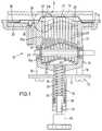
- the peristaltic pump 10is mounted in a recess 12 in a front wall 11 of the housing of an infusion device. It consists of the rigid frame 13 with the counter bearing 14, the squeezing device 15 and the pressing device 16.
- the frame 13has a base part 17 and four rods 18 projecting therefrom.
- the counter bearing 14is attached via a joint, which is designed as a hinged door and can be attached to the other two rods 18 with a quick release.
- a drive motor(not shown), which is fastened to the pump housing 21, drives via a reduction gear the camshaft 22 mounted in the pump housing 21.
- the camshaft 22consists of a shaft 23 with a hexagonal profile and cam disks 24 seated on this shaft, each of which has a hexagonal opening and thereby sits on the shaft 23 in a rotationally fixed manner.
- Two cam disks 24each form a double cam disk. Adjacent cam disks are circumferentially offset from one another by 30 ° on the shaft 23 and have an eccentricity of 2.5 mm, which results in a stroke of 5 mm with a full rotation of the cam disk.
- Each of the cam disks 24drives a slide 25.
- the slidesare guided in the pump housing 27 so that they can be moved longitudinally in lateral grooves and they run through slots 26 in the wall of the pump housing facing the counter bearing 14, a thickened head 27 being arranged at the end of each slide 25 .
- the bearing play of the guide grooves for the slider 25is selected so that the heads of adjacent slides just touch, but that tolerances of the slider or the heads do not add up.
- the heads 27 of the slideare covered by a membrane 28 which is attached to the pump housing 21.
- the pump housing 21also has flanges 29 with which it is fastened to the housing wall 11 of the device housing.
- the pump housing 21is guided with sliding bushes along the rods 18, so that the frame 13 relative to the pump housing 21 or to the crimping device 15 in Longitudinal direction of the rods can be moved.
- the counter bearing 14When the counter bearing 14 is in the closed position, it is a rigid component of the frame 13 and can be displaced horizontally with it relative to the housing wall 11 or to the crimping device 15 fastened therein.
- a spring device 33consisting of at least one compression spring is supported on the rear side of the pump housing 21.
- the spring device 33is contained in a tube 34 which is connected to the pump housing 21 and which telescopically plunges into a tube 35 projecting rearward from the base part 17.
- At the end of the tube 35there is an adjusting device 36, which engages with a thread in an internal thread 37 of the tube 35 and presses with its end against the spring device 33.
- the spring force of the pressing device 16can be changed by rotating the adjusting device 36.
- the spring device 33engages centrally on the base part 17 and on the squeezing device 15, i.e. along the central axis of the crimping device.
- a slider 38is provided, which enables low-friction sliding of the two tubes 34 and 35 and which, together with the sliding bushes 32, ensures that the frame 13 is guided in a linearly displaceable manner without tilting relative to the squeezing device 15.
- the hose 40which runs vertically between the membrane 28 and the counterbearing 14, is squeezed out at least in every phase of the rotation of the camshaft 22 by at least one slide 25. Any tolerances of the pump and / or hose are compensated for by the pressing device 16, which causes the frame 13 together with the counter bearing 14 against the squeezing device by the spring device 33 15, and thus also driven against the slide 25.
- a push button 39is slidably arranged on the pump housing 21, which pushes against the membrane 28 and against the outlet region of the pump hose.
- the push button 39is coupled to a sensor (not shown) which detects the position of the push button 39 and thereby determines the output pressure of the pump.
- the camshaft 22controls the slide 25 so that the hose 40 is continuously compressed and squeezed by the heads 27, the compression progressing in the conveying direction, that is to say from right to left in the drawings of this exemplary embodiment.
- the slidersact on the pumping area of the tubing in a section that encompasses 360 ° of the pumping cycle, i.e. the first and the last slide are controlled in phase.
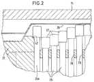
- Fig. 3the state is shown that the first in the conveying direction and the last in the conveying direction slide 25 are both in the extreme advanced state.
- the intermediate slides 25are withdrawn to a greater or lesser extent, so that the volume V F enclosed by the hose 40 in this area represents the delivery volume which is enclosed on all sides at this moment and which is advanced in the direction of delivery.
- the heads 27assume a position which enables the hose to assume the undeformed (round) state.
- the hose itselfhas its own resilience.
- the last slide 25a in the conveying directionis generally designed in the same way as the other slide 25 and the cam disk 24a controlling it has the same shape as the other cam disks 24. It is different that a return stroke limiting device is provided which does not allow the slide 25a, withdraw as far as the other slides 25.
- This return stroke limiting deviceconsists of a stop 42 which is provided on the housing 21 and against which the head 27a of the slider 25a abuts during the retraction movement. This stop 42 is arranged so that the slider 25a in the extreme retracted position, that is, when its head 27a abuts the stop 42, takes up half of the hose diameter (or a little more), as can be seen from FIG. 4.
- the hose volume V 1is also hatched, which is excluded from the release during the retraction movement of the slide 25 a and which contributes to the reduction or elimination of the back suction. If the slider 25a moved back as far as the other sliders, then the hose widening in this area would cause a backward suction.
- a gap 43is provided in the slide 25a, in which the cam disk 24a moves and which permits a longitudinal movement of the cam disk 24a with respect to the slide 25a.
- the required play of the camshaft in relation to the slide 25ais thereby achieved.
- the slide 25ais designed in the same way as the slide 25 and the cam disk 24a is designed in the same way as the cam disks 24.
Landscapes
- Engineering & Computer Science (AREA)
- Mechanical Engineering (AREA)
- General Engineering & Computer Science (AREA)
- Reciprocating Pumps (AREA)
- Details Of Reciprocating Pumps (AREA)
- External Artificial Organs (AREA)
Abstract
Description
Translated fromGermanDie Erfindung betrifft eine Schlauchpumpe der im Oberbegriff des Patentanspruchs 1 angegebenen Art.The invention relates to a hose pump of the type specified in the preamble of claim 1.
Im medizinischen Bereich werden häufig lineare Schlauchpumpen als Infusionspumpen verwendet, um Flüssigkeit aus einem Vorratsbehälter dem Körper eines Patienten zuzuführen. Die Schlauchpumpe weist einen Schlauch auf, der als preisgünstiger steriler Einmalartikel in das Pumpengehäuse eingesetzt wird. Der Schlauch wird durch eine Quetschvorrichtung abgedrückt, die zahlreiche von einer Nockenwelle angetriebene Schieber aufweist, welche zyklisch in unterschiedlichen Phasenlagen auf den Pumpenschlauch einwirken und diesen abquetschen. Der Schlauch besitzt eine Rückstellfähigkeit, so daß er sich bei einem Rückzug eines Schiebers an dieser Stelle wieder aufweitet.In the medical field, linear peristaltic pumps are often used as infusion pumps to deliver liquid from a reservoir to a patient's body. The peristaltic pump has a tube that is inserted into the pump housing as an inexpensive, sterile, disposable item. The hose is pressed off by a squeezing device, which has numerous sliders driven by a camshaft, which act cyclically on the pump hose in different phases and squeeze it out. The hose has a resilience, so that it widens again at this point when a slide is withdrawn.
Ein Problem bei derartigen Schlauchpumpen besteht darin, daß sie bei dem Rückhub des letzten Schiebers eine Rückzugsphase im Medium verursachen. Dieser Effekt wird dadurch hervorgerufen, daß nach dem Zurückziehen des letzten Schiebers das jetzt freiwerdende Schlauchinnenvolumen größer ist als das zu diesem Zeitpunkt nachgeförderte Medienvolumen. Durch den sich wieder aufweitenden Schlauch entsteht ein Sog und somit ein Rückfluß. Dieser Rückzug ist besonders bei kleinen Förderraten und erhöhtem Gegendruck nachteilig, da für einen gewissen Zeitraum eine deutliche Rückförderung erfolgt. Bei medizinischen Schlauchpumpen kann diese Rückförderung verhängnisvolle Folgen haben, weil Blut in die Kanüle eingesaugt werden kann, durch die das Medikament dem Patienten zugeführt werden soll.A problem with such peristaltic pumps is that they cause a retraction phase in the medium on the return stroke of the last slide. This effect is caused by the fact that after the last slide has been pulled back, the inner volume of the hose that is now free is greater than the volume of media that has been added at this point in time. The widening hose creates suction and thus backflow. This withdrawal is particularly disadvantageous in the case of low delivery rates and increased back pressure, since there is a clear return delivery for a certain period of time. With medical peristaltic pumps, this return delivery can have fatal consequences because blood can be drawn into the cannula through which the medication is to be delivered to the patient.
DE 31 04 873 A1 beschreibt eine Vorrichtung, mit der bei einer Schlauchpumpe Pulsationen verhindert werden können. Bei dieser Vorrichtung sind zusätzlich zu den Pumpenschiebern zwei weitere von der Nockenwelle angetriebene Schieber vorhanden, deren Antriebsnocken sich von denjenigen der anderen Schieber unterscheiden. Die zusätzlichen Schieber sind so gesteuert, daß sie eine gegenphasige Pulsation erzeugen und in denjenigen Zeiten, in denen die normalen Schieber einen Rückfluß verursachen würden, einen Druck aufbauen. Die Mediendrücke, die durch die normalen Pumpenschieber und die zusätzlichen Schieber erzeugt werden, ergänzen sich gegenseitig in der Weise, daß ein nahezu konstanter Förderdruck erreicht wird. Nachteilig ist jedoch, daß ein erheblicher Aufwand an zusätzlichen Bauelementen erforderlich ist, daß die Pumpe in ihren baulichen Abmessungen vergrößert wird und daß auch eine erhöhte Reibung auftritt.DE 31 04 873 A1 describes a device with which pulsations can be prevented in a peristaltic pump. In this device, in addition to the pump slides, there are two further slides driven by the camshaft, the drive cams of which differ from those of the other slides. The additional spools are controlled to produce an out of phase pulsation and build up pressure at times when the normal spools would cause reflux. The media pressures, which are generated by the normal pump slide and the additional slide, complement each other in such a way that an almost constant delivery pressure is achieved. However, it is disadvantageous that a considerable expenditure of additional components is required, that the structural dimensions of the pump are enlarged and that increased friction also occurs.
Aus US 4 952 124 ist eine Fingerpumpe bekannt, mit der das Problem des Rückflusses vermieden oder vermindert werden soll, indem zwei der im mittleren Bereich der Pumpenlänge vorgesehenen Finger breiter sind als die übrigen Finger. Durch Verbreiterung ausgewählter Pumpenfinger wird der mechanische Aufbau der Pumpe komplizierter bzw. im Falle der Verdopplung einzelner Pumpenfinger wird eine größere Anzahl von Fingern benötigt.A finger pump is known from US Pat. No. 4,952,124, with which the problem of backflow is to be avoided or reduced, in that two of the fingers provided in the middle region of the pump length are wider than the other fingers. By widening selected pump fingers, the mechanical structure of the pump becomes more complicated, or in the case of doubling individual pump fingers, a larger number of fingers is required.
Eine mögliche Lösung des Problems würde darin bestehen, in dem Schlauch-Überleitungssystem ein Rückschlagventil anzuordnen. Hierdurch würde jedoch das Überleitungssystem, das aus Einmalartikeln besteht, verteuert werden. Es würden sich hohe Betriebsfolgekosten ergeben.One possible solution to the problem would be to place a check valve in the hose transfer system. However, this would make the transfer system, which consists of disposable items, more expensive. There would be high follow-up costs.
Der Erfindung liegt die Aufgabe zugrunde, eine einfache, wirkungsvolle und das Pumpsystem nicht behindernde oder belastende Maßnahme zur Verminderung der Pulsation bzw. des Rückzuges bei einer Schlauchpumpe anzugeben.The invention has for its object to provide a simple, effective and the pumping system not obstructing or stressful measure to reduce the pulsation or withdrawal in a peristaltic pump.
Die Lösung dieser Aufgabe erfolgt erfindungsgemäß mit den im Patentanspruch 1 angegebenen Merkmalen.This object is achieved according to the invention with the features specified in claim 1.
Bei der erfindungsgemäßen Schlauchpumpe ist der in Förderrichtung letzte Schieber derart gesteuert, daß er auch im zurückgezogenen Zustand den Schlauch noch teilweise zusammengedrückt hält. Während die übrigen Schieber den Schlauch in der Rückzugsposition jeweils freigeben, so daß der Schlauchquerschnitt sich wenigstens annähernd auf den Ursprungszustand zurückstellen kann, wird der letzte Schieber nur zwischen der Schließposition und einer teilweisen Öffnungsstellung des Schlauchs bewegt. Der Rückhub des Schiebers erfolgt lediglich so weit, daß der Schlauchquerschnitt in einem Maße geöffnet wird, daß keine strömungstechnischen Nachteile auftreten. Dadurch, daß der letzte Schieber nur teilweise zurückgezogen wird, verkleinert sich das bei Neubeginn des Pumpzyklus am Ende des Pumpenbereichs des Schlauchs freiwerdende Volumen. Das Verhältnis zwischen freiwerdendem Volumen und nachgefördertem Volumen pro Zeiteinheit wird durch diese Maßnahme wesentlich verringert, d.h. verbessert. Ein weiterer Vorteil besteht darin, daß das Fördervolumen pro Pumpzyklus durch die Einengung des Pumpenschlauchs nicht beeinflußt wird. Das Fördervolumen der Pumpe wird während der Zeit definiert, in welcher der erste und der letzte Schieber den Schlauch (gleichzeitig) zusammendrücken. Das dann im Schlauch befindliche Volumen wird nachfolgend vorgetrieben und gefördert.In the hose pump according to the invention, the last slide in the conveying direction is controlled in such a way that it keeps the hose partially compressed even in the retracted state. While the other slides release the hose in the retracted position, so that the hose cross section can at least approximately return to the original state, the last slider is only between the closed position and a partial open position of the hose moved. The return stroke of the slide takes place only to such an extent that the hose cross section is opened to such an extent that there are no aerodynamic disadvantages. Because the last slide is only partially retracted, the volume released when the pump cycle starts again at the end of the pump area of the hose is reduced. The ratio between the volume released and the volume conveyed per unit of time is significantly reduced, ie improved, by this measure. Another advantage is that the delivery volume per pump cycle is not affected by the narrowing of the pump hose. The delivery volume of the pump is defined during the time in which the first and the last slide compress the hose (at the same time). The volume in the hose is then advanced and conveyed.
Vorzugsweise wirkt auf den letzten Schieber eine Rückhubbegrenzungseinrichtung ein, die zweckmäßigerweise aus einem gehäusefesten Anschlag besteht. Dies hat den Vorteil einer sehr einfachen Ausführungsform, die keinerlei zusätzliche Bauteile oder Komponenten erfordert. Ein weiterer Vorteil besteht darin, daß der Steuernocken des letzten Schiebers in gleicher Weise ausgebildet sein kann wie die Steuernocken der übrigen Schieber. Natürlich müssen sämtliche Steuernocken der Nockenwelle umfangsmäßig gegeneinander versetzt sein. Die Schlauchpumpe kann daher generell mit den Komponenten üblicher Schlauchpumpen aufgebaut werden, wobei lediglich in dem letzten Schieber ggf. ein Schlitz vorzusehen ist, der es zuläßt, daß der zugehörige Steuernocken der Nockenwelle sich weiterdreht, während dieser Schieber durch den die Rückhubbegrenzungseinrichtung bildenden Anschlag festgehalten wird.A return stroke limiting device, which advantageously consists of a stop fixed to the housing, acts on the last slide. This has the advantage of a very simple embodiment that does not require any additional parts or components. Another advantage is that the control cam of the last slide can be designed in the same way as the control cam of the other slides. Of course, all of the camshaft control cams must be circumferentially offset from one another. The peristaltic pump can therefore generally be constructed with the components of conventional peristaltic pumps, only a slot possibly having to be provided in the last slide, which allows the associated control cam of the camshaft to continue to rotate while this slide is held by the stop forming the return stroke limiting device .
Im folgenden wird ein Ausführungsbeispiel der Erfindung unter Bezugnahme auf die Zeichnungen näher erläutert.An exemplary embodiment of the invention is explained in more detail below with reference to the drawings.
Es zeigen:
- Fig. 1
- einen Schnitt durch die Schlauchpumpe,
- Fig. 2
- in vergrößertem Maßstab die Einzelheit II aus Fig. 1,
- Fig. 3
- in gleicher Darstellung wie Fig. 1 den Zustand des gleichzeitigen Abquetschens des Schlauchs am vorderen und hinteren Ende des Pumpbereichs zur Verdeutlichung des abgegrenzten Fördervolumens und
- Fig. 4
- eine schematische Darstellung des durch den letzten Schieber in der Rückzugsposition verdrängten Volumens, das für den Rückzug des Fördermediums nicht mehr zur Verfügung steht.
- Fig. 1
- a section through the peristaltic pump,
- Fig. 2
- on an enlarged scale the detail II from FIG. 1,
- Fig. 3
- in the same representation as FIG. 1, the state of simultaneous squeezing of the hose at the front and rear end of the pump area to illustrate the delimited delivery volume and
- Fig. 4
- a schematic representation of the volume displaced by the last slide in the retreat position, which is no longer available for the retraction of the medium.
Die Schlauchpumpe 10 ist in einer frontseitigen Gehäusewand 11 des Gehäuses eines Infusionsgerätes in einer Aussparung 12 montiert. Sie besteht aus dem starren Rahmen 13 mit dem Gegenlager 14, der Quetschvorrichtung 15 und der Andrückvorrichtung 16. Der Rahmen 13 weist ein Basisteil 17 und vier davon abstehende Stangen 18 auf. An zwei der Stangen 18 ist über ein Gelenk das Gegenlager 14 angebracht, das als aufklappbare Tür ausgebildet ist und an den beiden anderen Stangen 18 mit einem Schnellverschluß befestigt werden kann.The
Ein (nicht dargestellter) Antriebsmotor, der an dem Pumpengehäuse 21 befestigt ist, treibt über ein Untersetzungsgetriebe die in dem Pumpengehäuse 21 gelagerte Nockenwelle 22. Die Nockenwelle 22 besteht aus einer Welle 23 mit Sechskantprofil und auf dieser Welle sitzenden Nockenscheiben 24, die jeweils eine Sechskantöffnung aufweisen und dadurch drehfest auf der Welle 23 sitzen. Je zwei Nockenscheiben 24 bilden eine Doppelnockenscheibe. Benachbarte Nockenscheiben sind umfangsmäßig um 30° zueinander versetzt auf der Welle 23 angeordnet und haben eine Exzentrizität von 2,5 mm, wodurch sich bei einer vollen Umdrehung der Nockenscheibe ein Hub von 5 mm ergibt.A drive motor (not shown), which is fastened to the
Jede der Nockenscheiben 24 treibt einen Schieber 25. Die Schieber sind in dem Pumpengehäuse 27 in seitlichen Nuten längsverschiebbar geführt und sie verlaufen durch Schlitze 26 der dem Gegenlager 14 zugewandten Wand des Pumpengehäuse hindurch, wobei am Ende eines jeden Schiebers 25 ein verdickter Kopf 27 angeordnet ist. Das Lagerspiel der Führungsnuten für die Schieber 25 ist so gewählt, daß sich die Köpfe benachbarter Schieber gerade berühren, daß sich jedoch Toleranzen der Schieber bzw. der Köpfe nicht addieren.Each of the
Die Köpfe 27 der Schieber sind von einer Membran 28 bedeckt, die an dem Pumpengehäuse 21 befestigt ist. Das Pumpengehäuse 21 weist ferner Flansche 29 auf, mit denen es an der Gehäusewand 11 des Gerätegehäuses befestigt ist. Ein Blendrahmen 30, der bündig und abdichtend in die Öffnung 12 der Gehäusewand 11 eingesetzt ist, bildet den äußeren Abschluß des Pumpengehäuses. Dieser Blendrahmen umschließt die Membran 28.The
Das Pumpengehäuse 21 ist mit Gleitbuchsen längs der Stangen 18 geführt, so daß der Rahmen 13 relativ zu dem Pumpengehäuse 21 bzw. zur Quetschvorrichtung 15 in Längsrichtung der Stangen bewegt werden kann. Wenn das Gegenlager 14 sich in der Schließstellung befindet, ist es starrer Bestandteil des Rahmens 13 und kann mit diesem relativ zur Gehäusewand 11 bzw. zu der darin befestigten Quetschvorrichtung 15 horizontal verschoben werden.The
An der Rückseite des Pumpengehäuses 21 ist eine aus mindestens einer Druckfeder bestehende Federvorrichtung 33 abgestützt. Die Federvorrichtung 33 ist in einem mit dem Pumpengehäuse 21 verbundenen Rohr 34 enthalten, das teleskopisch in ein von dem Basisteil 17 nach hinten abstehendes Rohr 35 eintaucht. Am Ende des Rohres 35 befindet sich eine Stellvorrichtung 36, die mit einem Gewinde in ein Innengewinde 37 des Rohres 35 eingreift und mit ihrem Ende gegen die Federvorrichtung 33 drückt. Durch Drehen der Stellvorrichtung 36 kann die Federkraft der Andrückvorrichtung 16 verändert werden. Die Federvorrichtung 33 greift an dem Basisteil 17 und an der Quetschvorrichtung 15 zentrisch an, d.h. entlang der Mittelachse der Quetschvorrichtung. Am Rohr 34 ist ein Gleitstück 38 vorgesehen, das ein reibungsarmes Gleiten der beiden Rohre 34 und 35 ermöglicht und das zusammen mit den Gleitbuchsen 32 dafür sorgt, daß der Rahmen 13 in Bezug auf die Quetschvorrichtung 15 verkantungsfrei linear verschiebbar geführt ist.A
Im Betrieb wird der Schlauch 40, der zwischen der Membran 28 und dem Gegenlager 14 vertikal verläuft, in jeder Phase der Umdrehung der Nockenwelle 22 durch mindestens einen Schieber 25 okklusiv abgequetscht. Etwaige Toleranzen von Pumpe und/oder Schlauch werden durch die Andrückvorrichtung 16 ausgeglichen, die durch die Federvorrichtung 33 bewirkt, daß der Rahmen 13 zusammen mit dem Gegenlager 14 gegen die Quetschvorrichtung 15, und somit auch gegen die Schieber 25 getrieben wird.In operation, the
Auf der Auslaßseite der Schlauchpumpe ist am Pumpengehäuse 21 ein Drucktaster 39 verschiebbar angeordnet, der gegen die Membran 28 und gegen den Auslaßbereich des Pumpenschlauchs drückt. Der Drucktaster 39 ist mit einem (nicht dargestellten) Sensor gekoppelt, der die Stellung des Drucktasters 39 feststellt und dadurch den Ausgangsdruck der Pumpe ermittelt.On the outlet side of the peristaltic pump, a
Beim Betrieb der Schlauchpumpe steuert die Nockenwelle 22 die Schieber 25 so, daß der Schlauch 40 fortlaufend von den Köpfen 27 zusammengedrückt und abgequetscht wird, wobei das Zusammendrücken in Förderrichtung fortschreitet, also in den Zeichnungen dieses Ausführungsbeispieles von rechts nach links. Die Schieber wirken auf den Pumpbereich des Schlauchs in einem Abschnitt, der 360° des Pumpzyklus umfaßt, d.h. der erste und der letzte Schieber sind gleichphasig gesteuert.During operation of the hose pump, the
In Fig. 3 ist der Zustand dargestellt, daß der in Förderrichtung erste und der in Förderrichtung letzte Schieber 25 beide im äußersten vorgeschobenen Zustand sind. Die dazwischenliegenden Schieber 25 sind mehr oder weniger weit zurückgezogen, so daß das in diesem Bereich vom Schlauch 40 eingeschlossene Volumen VF das Fördervolumen darstellt, das in diesem Augenblick allseitig umschlossen ist und das in Förderrichtung vorgeschoben wird. In der Rückzugsstellung der Schieber nehmen die Köpfe 27 eine Position ein, die es dem Schlauch ermöglicht, den unverformten (runden) Zustand anzunehmen. Der Schlauch selbst hat eine eigene Rückstellfähigkeit.In Fig. 3 the state is shown that the first in the conveying direction and the last in the conveying
Der in Förderrichtung letzte Schieber 25a ist generell in gleicher Weise ausgebildet wie die übrigen Schieber 25 und die ihn steuernde Nockenscheibe 24a hat die gleiche Form wie die übrigen Nockenscheiben 24. Unterschiedlich ist, daß eine Rückhubbegrenzungseinrichtung vorgesehen ist, die es dem Schieber 25a nicht erlaubt, sich soweit zurückzuziehen wie die übrigen Schieber 25. Diese Rückhubbegrenzungseinrichtung besteht aus einem Anschlag 42 der am Gehäuse 21 vorgesehen ist und gegen den der Kopf 27a des Schiebers 25a bei der Rückzugsbewegung stößt. Dieser Anschlag 42 ist so angeordnet, daß der Schieber 25a in der äußersten Rückzugsstellung, also wenn sein Kopf 27a gegen den Anschlag 42 stößt, die Hälfte des Schlauchdurchmessers (oder etwas mehr) einnimmt, so wie dies aus Fig. 4 zu ersehen ist. In dieser Darstellung ist außerdem schraffiert das Schlauchvolumen V₁ dargestellt, das bei der Rückzugsbewegung des Schiebers 25a von der Freigabe ausgeschlossen wird und das zur Verkleinerung oder Eliminierung des Rücksoges beiträgt. Würde der Schieber 25a sich so weit zurückbewegen wie die übrigen Schieber, dann würde durch den sich in diesem Bereich aufweitenden Schlauch ein Rücksog auftreten.The
Damit die Steuerung der Nockenscheibe 24a nicht mit der durch den Anschlag 42 bewirkten Rückhubbegrenzung kollidiert, ist in dem Schieber 25a ein Spalt 43 vorgesehen, in dem sich die Nockenscheibe 24a bewegt und der eine Längsbewegung der Nockenscheibe 24a in Bezug auf den Schieber 25a zuläßt. Dadurch wird das erforderliche Bewegungsspiel der Nockenwelle in Bezug auf den Schieber 25a erreicht. Im übrigen ist der Schieber 25a in gleicher Weise ausgebildet wie die Schieber 25 und die Nockenscheibe 24a ist in gleicher Weise ausgebildet wie die Nockenscheiben 24.So that the control of the
Claims (3)
Translated fromGermandadurch gekennzeichnet,
daß der in Förderrichtung letzte Schieber (25a) derart gesteuert ist, daß er auch im zurückgezogenen Zustand den Schlauch (40) noch teilweise zusammengedrückt hält.Peristaltic peristaltic slide valve (25), which is driven by a camshaft (22) and carries out stroke movements against the hose (40),
characterized,
that the last slide (25a) in the conveying direction is controlled in such a way that it keeps the hose (40) partially compressed even in the retracted state.
Applications Claiming Priority (2)
| Application Number | Priority Date | Filing Date | Title |
|---|---|---|---|
| DE4035182 | 1990-11-06 | ||
| DE4035182ADE4035182C1 (en) | 1990-11-06 | 1990-11-06 |
Publications (2)
| Publication Number | Publication Date |
|---|---|
| EP0484717A1true EP0484717A1 (en) | 1992-05-13 |
| EP0484717B1 EP0484717B1 (en) | 1994-09-07 |
Family
ID=6417698
Family Applications (1)
| Application Number | Title | Priority Date | Filing Date |
|---|---|---|---|
| EP91117858AExpired - LifetimeEP0484717B1 (en) | 1990-11-06 | 1991-10-19 | Hose pump |
Country Status (3)
| Country | Link |
|---|---|
| EP (1) | EP0484717B1 (en) |
| AT (1) | ATE111189T1 (en) |
| DE (2) | DE4035182C1 (en) |
Cited By (3)
| Publication number | Priority date | Publication date | Assignee | Title |
|---|---|---|---|---|
| EP1378663A3 (en)* | 2002-07-06 | 2005-01-05 | B. Braun Melsungen Ag | Peristaltic pump |
| FR2908165A1 (en)* | 2006-11-08 | 2008-05-09 | Fresenius Vial Soc Par Actions | METHOD FOR CONTROLLING THE FLOW OF A PERISTALTIC PUMP AND PERISTALTIC PUMP |
| WO2021226131A1 (en)* | 2020-05-04 | 2021-11-11 | The Board of Regents for the Oklahoma Agricultural and Mechanical Colleges | Peristaltic compressor |
Families Citing this family (9)
| Publication number | Priority date | Publication date | Assignee | Title |
|---|---|---|---|---|
| GR1001179B (en)* | 1992-03-10 | 1993-06-07 | Micrel Kentron Efarmogon Mikro | Portable linear peristaltic pump. |
| DE29706606U1 (en) | 1997-04-12 | 1997-08-21 | Kammerer, Rolf, 75196 Remchingen | Rotary displacement pump |
| DE202009001865U1 (en) | 2009-02-11 | 2010-07-22 | Krauss, Gunter | Pump, in particular peristaltic pump |
| US9163623B2 (en)* | 2011-12-08 | 2015-10-20 | Carefusion 303, Inc. | System and method for improved flow uniformity in a peristaltic pump mechanism |
| DE202018003997U1 (en) | 2018-08-28 | 2019-12-04 | Gunter Krauss | Pump, especially peristaltic pump |
| EP3757390A1 (en)* | 2019-06-25 | 2020-12-30 | maxon international ag | Two-part squeezing element for a peristaltic pump and method of making a two-parte squeezing element for a peristaltic pump |
| CN113397721A (en)* | 2021-06-04 | 2021-09-17 | 河北卫勤医疗科技有限公司 | Portable multifunctional integrated device for realizing life support and emergency treatment functions |
| DE102022118250A1 (en) | 2022-07-21 | 2024-02-01 | B. Braun Melsungen Aktiengesellschaft | Displacement unit for a medical peristaltic pump and medical peristaltic pump |
| DE102024102479A1 (en) | 2024-01-29 | 2025-07-31 | B. Braun Melsungen Aktiengesellschaft | Medical peristaltic pump |
Citations (2)
| Publication number | Priority date | Publication date | Assignee | Title |
|---|---|---|---|---|
| US4322201A (en)* | 1979-03-09 | 1982-03-30 | Avi, Inc. | IV Pump with back pressure control |
| US4781548A (en)* | 1987-04-10 | 1988-11-01 | Alderson Richard K | Infusion pump system and conduit therefor |
Family Cites Families (2)
| Publication number | Priority date | Publication date | Assignee | Title |
|---|---|---|---|---|
| JPS56113084A (en)* | 1980-02-12 | 1981-09-05 | Terumo Corp | Pulsation preventing method and device for peristaltic finger pump |
| JPS61228872A (en)* | 1985-04-01 | 1986-10-13 | シャープ株式会社 | Liquid drug injection apparatus |
- 1990
- 1990-11-06DEDE4035182Apatent/DE4035182C1/denot_activeExpired - Lifetime
- 1991
- 1991-10-19ATAT91117858Tpatent/ATE111189T1/enactive
- 1991-10-19DEDE59102830Tpatent/DE59102830D1/ennot_activeExpired - Fee Related
- 1991-10-19EPEP91117858Apatent/EP0484717B1/ennot_activeExpired - Lifetime
Patent Citations (2)
| Publication number | Priority date | Publication date | Assignee | Title |
|---|---|---|---|---|
| US4322201A (en)* | 1979-03-09 | 1982-03-30 | Avi, Inc. | IV Pump with back pressure control |
| US4781548A (en)* | 1987-04-10 | 1988-11-01 | Alderson Richard K | Infusion pump system and conduit therefor |
Cited By (8)
| Publication number | Priority date | Publication date | Assignee | Title |
|---|---|---|---|---|
| EP1378663A3 (en)* | 2002-07-06 | 2005-01-05 | B. Braun Melsungen Ag | Peristaltic pump |
| US7217108B2 (en) | 2002-07-06 | 2007-05-15 | B. Braun Melsungen Ag | Peristaltic hose pump |
| FR2908165A1 (en)* | 2006-11-08 | 2008-05-09 | Fresenius Vial Soc Par Actions | METHOD FOR CONTROLLING THE FLOW OF A PERISTALTIC PUMP AND PERISTALTIC PUMP |
| WO2008055794A1 (en)* | 2006-11-08 | 2008-05-15 | Fresenius Vial Sas | Method for controlling the capacity of a peristaltic pump and peristaltic pump |
| US8133035B2 (en) | 2006-11-08 | 2012-03-13 | Fresenius Vial Sas | Method for controlling the capacity of a peristaltic pump and peristaltic pump |
| CN101529093B (en)* | 2006-11-08 | 2013-03-06 | 弗雷泽纽斯维亚尔两合公司 | Method for controlling the capacity of a peristaltic pump and peristaltic pump |
| WO2021226131A1 (en)* | 2020-05-04 | 2021-11-11 | The Board of Regents for the Oklahoma Agricultural and Mechanical Colleges | Peristaltic compressor |
| US12228124B2 (en) | 2020-05-04 | 2025-02-18 | The Board of Regents for the Oklahoma Agricultural and Mechanical Colleges | Peristaltic compressor |
Also Published As
| Publication number | Publication date |
|---|---|
| ATE111189T1 (en) | 1994-09-15 |
| EP0484717B1 (en) | 1994-09-07 |
| DE4035182C1 (en) | 1992-01-02 |
| DE59102830D1 (en) | 1994-10-13 |
Similar Documents
| Publication | Publication Date | Title |
|---|---|---|
| EP0484717B1 (en) | Hose pump | |
| EP1549852B1 (en) | Pump device | |
| DE69430578T2 (en) | CONVEYOR SYSTEM FOR THE REGULATED INFUSION OF A LIQUID | |
| DE69921809T2 (en) | Patient controlled drug delivery devices | |
| DE69018208T2 (en) | Peristaltic pump with a mechanism to maintain a linear flow. | |
| EP0409001B1 (en) | Liquid injection device | |
| EP1075292B1 (en) | Injection device | |
| EP3468642B1 (en) | Dosing apparatus and injection device | |
| DE3150623C2 (en) | Pressure infusion apparatus for medical applications | |
| DE202004006611U1 (en) | Injection device for administering an injectable product with secured dosing device | |
| DE2746374A1 (en) | DEVICE FOR REGULATING THE INTRAVENOES ADMINISTRATION OF A LIQUID TO A PATIENT | |
| EP2449263B1 (en) | Device and method for pumping flowable masses | |
| DE3104873A1 (en) | METHOD AND DEVICE FOR PREVENTING PULSATIONS IN A PERISTALTIC FLUID INFUSION PUMP | |
| DE3726452A1 (en) | Peristaltic pump for medical purposes | |
| DE69303516T2 (en) | Linear peristaltic pump | |
| DE3237014A1 (en) | HOSE PUMP | |
| DE4213172C1 (en) | ||
| DE2942801A1 (en) | REGULATOR FOR A LIQUID DOSING DEVICE | |
| DE69007003T2 (en) | Peristaltic pump with two stages. | |
| EP0445387B1 (en) | Linear hose pump | |
| DE1186609B (en) | Injection molding machine for thermoplastics | |
| WO2021229096A1 (en) | Medical hose pump with plunger elements, and associated hose arrangement | |
| DE102020121665A1 (en) | Dosing system with a syringe and a syringe pump | |
| CH713379A2 (en) | Cannula insertion mechanism for a patch device. | |
| EP0800840A2 (en) | Peristaltic infusionpump |
Legal Events
| Date | Code | Title | Description |
|---|---|---|---|
| PUAI | Public reference made under article 153(3) epc to a published international application that has entered the european phase | Free format text:ORIGINAL CODE: 0009012 | |
| AK | Designated contracting states | Kind code of ref document:A1 Designated state(s):AT BE CH DE DK ES FR GB IT LI NL SE | |
| 17P | Request for examination filed | Effective date:19920630 | |
| 17Q | First examination report despatched | Effective date:19931124 | |
| GRAA | (expected) grant | Free format text:ORIGINAL CODE: 0009210 | |
| AK | Designated contracting states | Kind code of ref document:B1 Designated state(s):AT BE CH DE DK ES FR GB IT LI NL SE | |
| PG25 | Lapsed in a contracting state [announced via postgrant information from national office to epo] | Ref country code:IT Free format text:LAPSE BECAUSE OF FAILURE TO SUBMIT A TRANSLATION OF THE DESCRIPTION OR TO PAY THE FEE WITHIN THE PRE;WARNING: LAPSES OF ITALIAN PATENTS WITH EFFECTIVE DATE BEFORE 2007 MAY HAVE OCCURRED AT ANY TIME BEFORE 2007. THE CORRECT EFFECTIVE DATE MAY BE DIFFERENT FROM THE ONE RECORDED.SCRIBED TIME-LIMIT Effective date:19940907 Ref country code:BE Effective date:19940907 Ref country code:GB Effective date:19940907 Ref country code:NL Effective date:19940907 Ref country code:ES Free format text:THE PATENT HAS BEEN ANNULLED BY A DECISION OF A NATIONAL AUTHORITY Effective date:19940907 Ref country code:FR Effective date:19940907 Ref country code:DK Effective date:19940907 | |
| REF | Corresponds to: | Ref document number:111189 Country of ref document:AT Date of ref document:19940915 Kind code of ref document:T | |
| REF | Corresponds to: | Ref document number:59102830 Country of ref document:DE Date of ref document:19941013 | |
| PG25 | Lapsed in a contracting state [announced via postgrant information from national office to epo] | Ref country code:AT Effective date:19941019 | |
| PG25 | Lapsed in a contracting state [announced via postgrant information from national office to epo] | Ref country code:LI Effective date:19941031 Ref country code:CH Effective date:19941031 | |
| PGFP | Annual fee paid to national office [announced via postgrant information from national office to epo] | Ref country code:DE Payment date:19941115 Year of fee payment:4 | |
| PG25 | Lapsed in a contracting state [announced via postgrant information from national office to epo] | Ref country code:SE Effective date:19941207 | |
| EN | Fr: translation not filed | ||
| NLV1 | Nl: lapsed or annulled due to failure to fulfill the requirements of art. 29p and 29m of the patents act | ||
| GBV | Gb: ep patent (uk) treated as always having been void in accordance with gb section 77(7)/1977 [no translation filed] | Effective date:19940907 | |
| REG | Reference to a national code | Ref country code:CH Ref legal event code:PL | |
| PLBE | No opposition filed within time limit | Free format text:ORIGINAL CODE: 0009261 | |
| STAA | Information on the status of an ep patent application or granted ep patent | Free format text:STATUS: NO OPPOSITION FILED WITHIN TIME LIMIT | |
| 26N | No opposition filed | ||
| PG25 | Lapsed in a contracting state [announced via postgrant information from national office to epo] | Ref country code:DE Effective date:19960702 |