EP0482604B1 - Distance detecting apparatus for a vehicle - Google Patents
Distance detecting apparatus for a vehicleDownload PDFInfo
- Publication number
- EP0482604B1 EP0482604B1EP91118063AEP91118063AEP0482604B1EP 0482604 B1EP0482604 B1EP 0482604B1EP 91118063 AEP91118063 AEP 91118063AEP 91118063 AEP91118063 AEP 91118063AEP 0482604 B1EP0482604 B1EP 0482604B1
- Authority
- EP
- European Patent Office
- Prior art keywords
- vehicle
- windows
- detecting apparatus
- objects
- image
- Prior art date
- Legal status (The legal status is an assumption and is not a legal conclusion. Google has not performed a legal analysis and makes no representation as to the accuracy of the status listed.)
- Expired - Lifetime
Links
Images


Classifications
- G—PHYSICS
- G01—MEASURING; TESTING
- G01S—RADIO DIRECTION-FINDING; RADIO NAVIGATION; DETERMINING DISTANCE OR VELOCITY BY USE OF RADIO WAVES; LOCATING OR PRESENCE-DETECTING BY USE OF THE REFLECTION OR RERADIATION OF RADIO WAVES; ANALOGOUS ARRANGEMENTS USING OTHER WAVES
- G01S11/00—Systems for determining distance or velocity not using reflection or reradiation
- G01S11/12—Systems for determining distance or velocity not using reflection or reradiation using electromagnetic waves other than radio waves
- G—PHYSICS
- G01—MEASURING; TESTING
- G01B—MEASURING LENGTH, THICKNESS OR SIMILAR LINEAR DIMENSIONS; MEASURING ANGLES; MEASURING AREAS; MEASURING IRREGULARITIES OF SURFACES OR CONTOURS
- G01B11/00—Measuring arrangements characterised by the use of optical techniques
- G01B11/02—Measuring arrangements characterised by the use of optical techniques for measuring length, width or thickness
- G01B11/026—Measuring arrangements characterised by the use of optical techniques for measuring length, width or thickness by measuring distance between sensor and object
- G—PHYSICS
- G08—SIGNALLING
- G08G—TRAFFIC CONTROL SYSTEMS
- G08G1/00—Traffic control systems for road vehicles
- G08G1/16—Anti-collision systems
- G08G1/167—Driving aids for lane monitoring, lane changing, e.g. blind spot detection
Definitions
- the present inventionrelates to a distance detecting apparatus for a vehicle.
- DE-A-4 006 989discloses a tracking distance detecting apparatus for a vehicle comprising a pair of first and second image sensors including a pair of optical systems for optically sensing a single object.
- the apparatusadditionally has a first memory for storing the image of the object, a second memory for storing the image of the object, a display with a screen for displaying the images of the single object, window defining means for defining a plurality of windows at specific locations on the screen of the display, distance calculating means for electrically detecting deviations between the images of the single object within the respective windows, and for calculating the distance to the single object in the windows based on the calculated deviations. Since this prior art distance detecting apparatus involves tracking of an object, the prior art apparatus is not only capable of determining the distance to an object, but is also capable of determining the velocity of movement of the object.
- US-4 749 848discloses a distance detecting apparatus which is only capable of determining distances, but not capable of determining velocities.
- This prior art distance detecting apparatuscomprises first and second image sensors, a pair of optical systems, image memories, and distance calculating means. Distance measurement information obtained from the distance detecting apparatus may be used for avoiding a collision with an object.
- Each one of the surfaces of the first and second image sensorsis divided into blocks. In each block of the first sensor, at least some of the light-receiving elements in the block are selected as so-called standard view fields. In a similar manner, in each block of the second sensor, some elements are selected as so-called reference view fields.
- an obstacle detecting apparatusSome examples of an obstacle detecting apparatus are disclosed in Japanese Patent Laid-Open 55-15337 and Japanese Utility Model Laid-Open 1-12221. These apparatuses project ultrasonic waves or electromagnetic waves in a specified forward or backward direction to be detected and receive reflected waves from an object or obstacle for the purpose of determining the presence or absence of an obstacle as well as measuring the distance thereto.
- Examples of an optical distance detecting apparatus utilizing image sensorsare known from Japanese Patent Publication Nos. 63-38085 and 63-46363.
- the apparatuses disclosed thereincommonly have a pair of first and second parallel optical systems having two convex lenses 101, 102 disposed in a horizontally aligned relation at a prescribed distance L away from each other, as shown in Fig. 5.
- a pair of separate image sensors 103, 104are horizontally disposed at focal points of the lenses 101, 102 at a distance f from the locations of corresponding lenses 101, 102, respectively, for generating respective image signals to a common signal processor 120.
- Japanese Patent Publication No. 63-18122discloses an obstacle detecting apparatus for a vehicle which is provided with a plurality of light emitting elements or light transmitters each projecting a beam of light toward objects to be detected for the purpose of improving the contrast of the image of an object sensed by the image sensors in the invent that no good image contrast is obtained.
- the distance and/or obstacle detecting apparatusesas described above, it is possible to detect the presence or absence of an object lying in the direction in which ultrasonic or electromagnetic waves or light are projected, but it is difficult to precisely determine whether the object thus detected is an obstacle to the travel of the vehicle.
- the obstacle detecting apparatus mounted thereoncan mididentify a guide rail, which is set up along one side or shoulder of the curved road and lies ahead of the cornering vehicle, as an obstacle.
- many ultrasonic or electromagnetic wave transmitters and receiversare required, thus resulting in a great increase in size and costs of manufacture of the overall apparatus.
- the present inventionis intended to overcome the above-mentioned problems encountered with the conventional apparatuses.
- An object of the inventionis to provide a novel and improved distance detecting apparatus for a vehicle in which the driver is able to readily and exactly recognize the location and direction of each of objects which are present within the wide field of view of the driver, and at the same time determine whether each of the objects is an obstacle to the travel of his or her vehicle as well.
- Another object of the inventionis provide a novel and improved distance detecting apparatus for a vehicle which is able to concurrently detect the distances to a plurality of objects which exist within the field of view of the driver, and in which the driver is able to readily and accurately recognize to which objects the distances are detected.
- a further object of the inventionis to provide a novel and improved distance detecting apparatus for a vehicle which is able to sense a preceding vehicle running ahead of a subject vehicle on which the apparatus is mounted without dazzling the passengers in the preceding vehicle even during travelling in a tunnel or in dark weather such as in the evening, twilight and the like.
- a distance detecting apparatus for a vehiclecomprising: a pair of first and second image sensors including a pair of optical systems for optically sensing a plurality of objects; a first memory for storing the images of the objects sensed by the first image sensor as first image signals; a second memory for storing the images of the objects sensed by the second image sensor as second image signals; a display with a screen for displaying the images of the objects as sensed by the image sensors on the screen; window defining means for defining for each image sensor a plurality of windows at specific locations on the screen of the display; distance calculating means for electrically detecting for each object, deviations between the images of the objects within the respective windows as sensed by the image sensors and individually calculating the distance to each object in each window based on the calculated deviations; and obstacle discriminating means for discriminating, among the objects around the vehicle as sensed by the image sensors, obstacles to the travel of the vehicle on the basis of the positions of the windows on the screen and the
- the window defining meansmay define the plurality of windows in such a manner that the windows are disposed on the screen of the display in a horizontally separate relation with respect of each other, the windows including a central window located at the center of the screen, and a plurality of side windows located on the opposite sides of the central window.
- the obstacle discriminating meansdetermines that the image in the central window is the image of a preceding vehicle which a vehicle having the apparatus installed thereon follows.
- the apparatusfurther comprises means for determining, based on the rate of change of the distances as measured by the distance calculating means, whether an object displayed in each window is coming near or going away from a vehicle on which the apparatus is installed.
- a vehicle condition sensing meansfor determining whether a subject vehicle having the apparatus installed thereon is travelling on a curved road.
- the obstacle discriminating meansoperates to determine that the objects displayed in the windows are not obstacles impeding the travel of the subject vehicle, if it is determined that the subject vehicle is travelling on a curved road and if the distances to the objects displayed in the windows vary in a gradually decreasing or increasing manner in a horizontal direction from one side to the other side of the windows.
- An infrared light generating meanscan be provided for projecting a beam of infrared light toward objects present within the fields of view of the image sensors when natural visible light is insufficient for the image sensors.
- the image sensorsare sensitive to infrared light as well.
- Fig. 1illustrates, in a block diagram, the schematic arrangement of a distance detecting apparatus which is constructed in accordance with the principles of the invention and which is mounted on a vehicle for detecting the distances to objects such as preceding vehicles, obstacles and the like lying ahead of the subject vehicle.
- the apparatus illustratedincludes a pair of first and second parallel optical systems having two convex lenses 1, 2 disposed in a vertically aligned relation at a prescribed distance L away from each other, and a pair of separate first and second (e.g., upper and lower) image sensors 3, 4 which are vertically or otherwise disposed at focal points of the lenses 1, 2, respectively, at a distance f from the locations of the corresponding lenses 1, 2 for generating first and second image signals in the form of analog signals representative of a two-dimensional image, which are input to a pair of corresponding first and second analog-to-digital (A/D) converters 6, 7.
- the outputs of the A/D converters 6, 7are input to a pair of corresponding first and second memories 8, 9 and stored therein.
- a microcomputer 10which acts as a distance calculating means and an obstacle discriminating means as claimed of the invention, performs data transfer with the memories 8, 9 so that it makes various calculations and determinations based on the data stored in the memories 8, 9.
- a display 11 having a screenis connected to the first and second memories 8, 9 and the microcomputer 10 for displaying the images of objects sensed by the first or second image sensor 8, 9 on the screen. The operation of the display 11 is controlled by the microcomputer 10.
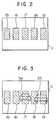
- a window defining means 12is connected to the microcomputer 10 for defining on the screen of the display 11 a plurality of windows which can be utilized for designating a plurality of objects for distance measurements. More specifically, as shown in Fig.
- the driver of a vehiclecan manipulate the window defining means 12 to define a plurality (e.g., five in the illustrated embodiment) of windows 15 through 19 on the screen of the display 11 at horizontally spaced or separate predetermined locations thereof while looking at the screen.
- a vehicle condition sensing means 13 in the form of a steering angle sensorsenses the amount or angle of steering representative of the rotational angle of a steering wheel of the vehicle and generates a corresponding steering angle signal to the microcomputer 10.
- An alarm 14 in the form of a buzzeris actuated by the microcomputer 10 to generate a warning when the distance to an object 5 such as a preceding vehicle decreases to a predetermined level.
- the microcomputer 10selects a specific area corresponding to the window 17 from the first memory 8, which stores image signals of objects sensed by the first or lower image sensor 3. Then, the microcomputer 10 calculates a total sum of the absolute values of the differences or deviations between the corresponding image signals for the first and second picture elements stored in the first and second memories 8, 9 while vertically shifting the image signals from the first memory 8 relative to the above defined reference image signals in a stepwise manner one picture element by one picture element. In other words, by sequentially shifting the second memory image signals one picture element by one picture element, the best position of the image of the object in the first memory 8 is determined in which the image in the first memory 8 best matches the reference image. Thus, the amount of shift or shift distance of the second memory image 5a relative to the reference image is calculated which minimizes the total sum of the absolute values of the deviations.
- the area in the first memory 8 relating to the above calculationis a vertically extending band-shaped image area 22, as shown in Fig. 4(b), which corresponds to the position of the window 17 in which the reference image exists.
- the distance R to the object 5 imaged in the window 17can be measured.
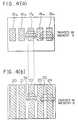
- the microcomputer 10makes the image signals 19a inside a window 19 as reference picture signals as shown in Fig. 4(a), selects an image area 24 in the first memory 8 corresponding to the image signals 19a of the second memory 9 inside the window 19, and determines the position of the image of the vehicle 25 in the first memory 8 which provides the best match with the image inside the window 19. Then, using equation (1) above, the distance to the other vehicle 25 is calculated in the same manner.
- the objects caught in the plurality of windows 15 through 19 defined on the screen of the display 11 and stored in the second memory 9 as corresponding image signals 15a to 19a, as shown in Fig. 4(a),are compared with the images thereof in the image areas (calculation areas) of the memory 8, that is the image areas 20 through 24, respectively, as shown in Fig. 4(b), whereby the distances to the respective objects can substantially concurrently be measured using the individual windows 15 through 19.
- the microcomputer 10actuates the alarm 14, warning to the driver of the presence of an obstacle in the form of the preceding vehicle lying ahead of the subject vehicle.
- the distances to the respective portions of the guide rail 27 caught in the respective windows 15 through 19are detected or measured in the same manner as in the case of the preceding vehicle.
- the distances as detected by the right-side windows 18, 19 lying to the right of the central window 17 in the center of the screen 11are shorter than that detected by the central window 17, whereas the distances as detected by the left-side windows 15, 16 are longer than that detected by the central window 17.
- the microcomputer 10determines that an object caught in the central window 17 on the screen 11 is not an obstacle impeding the travel of the vehicle. As a result, even if the distance detected by the central window 17 is short, it is determined that there is no problem, and hence the alarm 14 is not actuated. In this manner, on the basis of the information on the distances to objects ahead of the subject vehicle as detected by the respective windows 15 through 19, it can be precisely determined whether the objects as detected and displayed by the respective windows 15 through 19 are true obstacles to the travel of the subject vehicle.
- the number of such windowscan be arbitrarily selected depending on the dimensions of objects within the fields of view of the image sensors 3, 4, the number of objects to which distance measurements are required, etc.
- the size and configuration of each windowcan be arbitrarily changed according to an object to be detected.
- the positions of windows as set on the screen 11can be varied according to ranges or fields to be detected, is shown in Fig. 6.
- the present inventioncan be applied for detecting or supervising objects present in the rear vision of a vehicle. Further, according to the invention, it is possible to calculate the rate of change of the distance to an object caught by each of the windows 15 through 19 so as to determine whether or not the object is coming near or going away from the subject vehicle.
- the lenses 1, 2 and the image sensors 3, 4are disposed in a vertically aligned and spaced relationship with respect to each other, they may be disposed in a modified manner, e.g., diagonally on a vertical plane, such that they are disposed substantially vertically. Obviously, such modified arrangement provides substantially the same results.
- Fig. 7shows another embodiment of the invention. This embodiment is substantially similar to the previous embodiment of Fig. 1 except for the following.
- An infrared light generating means 30is provided for projecting a beam of infrared light to objects for detecting them in dark weather in which there is insufficient natural visible light.
- the infrared light generating means 30comprises a light generator 31 in the form of a halogen lamp for generating a beam of light including visible light components and infrared light components, and an infrared light filter 32 for filtering or removing almost all of visible light components from the light generated by the light generator 31 while passing infrared light components alone.
- the infrared light beam projected from the light generator 31 through the filter 32 to an object 5is reflected from a surface thereof and received by a pair of first and second image sensors 3', 4' through respective lenses 1, 2.
- the image sensors 3', 4'are sensitive to infrared light as well as visible light.
- the images of the object 5 thus sensed by the image sensors 3', 4'are stored in corresponding memories 8, 9 and then processed by a microcomputer 10 in the same manner as in the previous embodiment.
- the image of the object 5 sensed by the second image sensor 7is displayed on the screen of a display 11 within a plurality of windows which are appropriately set thereon in advance.
- the light generator 31projects a light beam toward the object 5 with the angle of projection B which is set to be less than the angle of field A of the image sensors 3', 4' through the lenses 1, 2, as shown in Fig. 7, such that the infrared light reflected from the object 5 can be received by the image sensors 3', 4'. More specifically, the light beam is projected to those areas of objects which can be sensed by the image sensors 3', 4' and displayed within the plurality of windows preset on the screen 11.
- the steering angle sensor 13 and the alarm 14 as employed with the previous embodiment of Fig. 1are omitted but may be provided as necessary.
- the operation of the second embodimentis substantially similar to that of the first embodiment in cases where sufficient natural light is available such as during day time.
- the light generator 31is energized to generate a beam of light which is filtered by the infrared light filter 32 so that infrared light components alone are passed onto an object 5 such as a preceding vehicle.
- the infrared light reflected from a surface of the object 5is sensed by the first and second image sensors 3', 4'.
- the images of the object 5 thus sensedare converted by the A/D converters 6, 7 from analog into digital form and stored in the first and second memories 8, 9.
- the microcomputer 10fetches picture element signals from the memories 8, 9 and processes them and displays the image of the object 5 as sensed by the second image sensor 4 on the screen of the display 11 in the same manner as in the previous embodiment.
- objects present in the darkcan be detected and the distances thereto can be precisely measured in the same manner as in bright weather.
- the projection of infrared light including little or no visible light componentsdoes not cause any dazzling of the driver or passengers in the preceding vehicle 5, so the driver in the preceding vehicle can maneuver his or her vehicle without any resultant trouble or inconvenience.
- the infrared light generating means 30comprises a combination of the light generator 31 and the infrared light filter 32, it is not limited to such an arrangement but may take any other appropriate form which can generate a beam of infrared light while excluding almost all of visible light components.
Landscapes
- Physics & Mathematics (AREA)
- General Physics & Mathematics (AREA)
- Electromagnetism (AREA)
- Engineering & Computer Science (AREA)
- Radar, Positioning & Navigation (AREA)
- Remote Sensing (AREA)
- Measurement Of Optical Distance (AREA)
Description
- The present invention relates to a distance detecting apparatus for a vehicle. DE-A-4 006 989 discloses a tracking distance detecting apparatus for a vehicle comprising a pair of first and second image sensors including a pair of optical systems for optically sensing a single object. The apparatus additionally has a first memory for storing the image of the object, a second memory for storing the image of the object, a display with a screen for displaying the images of the single object, window defining means for defining a plurality of windows at specific locations on the screen of the display, distance calculating means for electrically detecting deviations between the images of the single object within the respective windows, and for calculating the distance to the single object in the windows based on the calculated deviations. Since this prior art distance detecting apparatus involves tracking of an object, the prior art apparatus is not only capable of determining the distance to an object, but is also capable of determining the velocity of movement of the object.
- US-4 749 848 discloses a distance detecting apparatus which is only capable of determining distances, but not capable of determining velocities. This prior art distance detecting apparatus comprises first and second image sensors, a pair of optical systems, image memories, and distance calculating means. Distance measurement information obtained from the distance detecting apparatus may be used for avoiding a collision with an object. Each one of the surfaces of the first and second image sensors is divided into blocks. In each block of the first sensor, at least some of the light-receiving elements in the block are selected as so-called standard view fields. In a similar manner, in each block of the second sensor, some elements are selected as so-called reference view fields.
- For facilitating to understand the subject matter of the present invention the technical background thereof will be briefly outlined hereinafter.
- Some examples of an obstacle detecting apparatus are disclosed in Japanese Patent Laid-Open 55-15337 and Japanese Utility Model Laid-Open 1-12221. These apparatuses project ultrasonic waves or electromagnetic waves in a specified forward or backward direction to be detected and receive reflected waves from an object or obstacle for the purpose of determining the presence or absence of an obstacle as well as measuring the distance thereto.
- Examples of an optical distance detecting apparatus utilizing image sensors are known from Japanese Patent Publication Nos. 63-38085 and 63-46363. As illustrated in Fig. 8, the apparatuses disclosed therein commonly have a pair of first and second parallel optical systems having two
convex lenses 101, 102 disposed in a horizontally aligned relation at a prescribed distance L away from each other, as shown in Fig. 5. A pair ofseparate image sensors lenses 101, 102 at a distancef from the locations ofcorresponding lenses 101, 102, respectively, for generating respective image signals to acommon signal processor 120. Thesignal processor 120 successively shifts the image signals from theimage sensors lenses 101, 102 to anobject 121 is calculated based on the principle of triangulation using the following formula:
- In addition, Japanese Patent Publication No. 63-18122 discloses an obstacle detecting apparatus for a vehicle which is provided with a plurality of light emitting elements or light transmitters each projecting a beam of light toward objects to be detected for the purpose of improving the contrast of the image of an object sensed by the image sensors in the invent that no good image contrast is obtained.
- With the distance and/or obstacle detecting apparatuses as described above, it is possible to detect the presence or absence of an object lying in the direction in which ultrasonic or electromagnetic waves or light are projected, but it is difficult to precisely determine whether the object thus detected is an obstacle to the travel of the vehicle. For example, when a vehicle is travelling on a curved road, the obstacle detecting apparatus mounted thereon can mididentify a guide rail, which is set up along one side or shoulder of the curved road and lies ahead of the cornering vehicle, as an obstacle. In addition, in order to exactly determine the location and direction of the object detected with respect to the moving vehicle, many ultrasonic or electromagnetic wave transmitters and receivers are required, thus resulting in a great increase in size and costs of manufacture of the overall apparatus.
- Moreover, if there are many objects within the field of view of the image sensors, it is unclear to which object the distance from the subject vehicle is being detected. In particular, let us assume that the distance to an object in the form of a preceding vehicle is detected by the above-described distante detecting apparatus mounted on the subject vehicle during the travel thereof. In this case, if another vehicle travelling on one of plural lanes of a road adjacent the one on which the subject vehicle is travelling comes into the field of view of the image sensors, it is not clear at all or the driver cannot tell to which vehicle (i.e., travelling on the same lane or on an adjacent lane) the distance is detected.
- Furthermore, in cases where the brightness or magnitude of external light is insufficient for proper distance detection by image sensors such as when the vehicle travels in a tunnel or in dark weather such as in the evening, twilight, etc., it is necessary to use a light emitting element which projects a beam of visible light toward a preceding vehicle. In this case, however, there is a fear that the passengers including the driver in the preceding vehicle are dazzled by the light from the light emitting element, making it difficult for the driver to properly maneuver his or her vehicle in a safe manner.
- Accordingly, the present invention is intended to overcome the above-mentioned problems encountered with the conventional apparatuses.
- An object of the invention is to provide a novel and improved distance detecting apparatus for a vehicle in which the driver is able to readily and exactly recognize the location and direction of each of objects which are present within the wide field of view of the driver, and at the same time determine whether each of the objects is an obstacle to the travel of his or her vehicle as well.
- Another object of the invention is provide a novel and improved distance detecting apparatus for a vehicle which is able to concurrently detect the distances to a plurality of objects which exist within the field of view of the driver, and in which the driver is able to readily and accurately recognize to which objects the distances are detected.
- A further object of the invention is to provide a novel and improved distance detecting apparatus for a vehicle which is able to sense a preceding vehicle running ahead of a subject vehicle on which the apparatus is mounted without dazzling the passengers in the preceding vehicle even during travelling in a tunnel or in dark weather such as in the evening, twilight and the like.
- In order to achieve the above objects, according to the present invention, there is provided a distance detecting apparatus for a vehicle comprising: a pair of first and second image sensors including a pair of optical systems for optically sensing a plurality of objects; a first memory for storing the images of the objects sensed by the first image sensor as first image signals; a second memory for storing the images of the objects sensed by the second image sensor as second image signals; a display with a screen for displaying the images of the objects as sensed by the image sensors on the screen; window defining means for defining for each image sensor a plurality of windows at specific locations on the screen of the display; distance calculating means for electrically detecting for each object, deviations between the images of the objects within the respective windows as sensed by the image sensors and individually calculating the distance to each object in each window based on the calculated deviations; and obstacle discriminating means for discriminating, among the objects around the vehicle as sensed by the image sensors, obstacles to the travel of the vehicle on the basis of the positions of the windows on the screen and the distances to the objects in the respective windows as detected.
- Preferred embodiments of the invention are indicated in the dependent claims.
- The window defining means may define the plurality of windows in such a manner that the windows are disposed on the screen of the display in a horizontally separate relation with respect of each other, the windows including a central window located at the center of the screen, and a plurality of side windows located on the opposite sides of the central window. The obstacle discriminating means determines that the image in the central window is the image of a preceding vehicle which a vehicle having the apparatus installed thereon follows.
- Preferably, the apparatus further comprises means for determining, based on the rate of change of the distances as measured by the distance calculating means, whether an object displayed in each window is coming near or going away from a vehicle on which the apparatus is installed.
- Preferably, a vehicle condition sensing means is provided for determining whether a subject vehicle having the apparatus installed thereon is travelling on a curved road. The obstacle discriminating means operates to determine that the objects displayed in the windows are not obstacles impeding the travel of the subject vehicle, if it is determined that the subject vehicle is travelling on a curved road and if the distances to the objects displayed in the windows vary in a gradually decreasing or increasing manner in a horizontal direction from one side to the other side of the windows.
- An infrared light generating means can be provided for projecting a beam of infrared light toward objects present within the fields of view of the image sensors when natural visible light is insufficient for the image sensors. In this case, the image sensors are sensitive to infrared light as well.
- The above and other objects, features and advantages of the invention will become more readily apparent from the detailed description of a few preferred embodiments of the invention taken in conjunction with the accompanying drawings.
- Fig. 1 is a schematic block diagram showing the general arrangement of a distance detecting apparatus for a vehicle in accordance with the present invention;
- Fig. 2 is an explanatory view showing a plurality of windows defined on the screen of a display;
- Fig. 3 is an explanatory view showing that a plurality of preceding vehicles running ahead of a vehicle come into some of the windows;
- Figs. 4(a) and 4(b) are explanatory views showing image areas to be compared with reference images each within a corresponding window;
- Fig. 5 is an explanatory view showing images displayed on the screen when the vehicle is travelling on a curved road;
- Fig. 6 is a view showing that the positions of windows on the screen are altered;
- Fig. 7 is a view similar to Fig. 1, but showing another embodiment of the invention; and
- Fig. 8 is a block diagram showing the general arrangement of a conventional distance detecting apparatus for a vehicle.
- In the figures, the same or corresponding parts are identified by the same symbols.
- A few preferred embodiments of the present invention will now be described in detail with reference to the accompanying drawings.
- Fig. 1 illustrates, in a block diagram, the schematic arrangement of a distance detecting apparatus which is constructed in accordance with the principles of the invention and which is mounted on a vehicle for detecting the distances to objects such as preceding vehicles, obstacles and the like lying ahead of the subject vehicle.
- The apparatus illustrated includes a pair of first and second parallel optical systems having two convex lenses 1, 2 disposed in a vertically aligned relation at a prescribed distance L away from each other, and a pair of separate first and second (e.g., upper and lower)
image sensors 3, 4 which are vertically or otherwise disposed at focal points of the lenses 1, 2, respectively, at a distancef from the locations of the corresponding lenses 1, 2 for generating first and second image signals in the form of analog signals representative of a two-dimensional image, which are input to a pair of corresponding first and second analog-to-digital (A/D)converters D converters second memories microcomputer 10, which acts as a distance calculating means and an obstacle discriminating means as claimed of the invention, performs data transfer with thememories memories display 11 having a screen is connected to the first andsecond memories microcomputer 10 for displaying the images of objects sensed by the first orsecond image sensor display 11 is controlled by themicrocomputer 10. A window defining means 12 is connected to themicrocomputer 10 for defining on the screen of the display 11 a plurality of windows which can be utilized for designating a plurality of objects for distance measurements. More specifically, as shown in Fig. 2, the driver of a vehicle can manipulate the window defining means 12 to define a plurality (e.g., five in the illustrated embodiment) ofwindows 15 through 19 on the screen of thedisplay 11 at horizontally spaced or separate predetermined locations thereof while looking at the screen. A vehicle condition sensing means 13 in the form of a steering angle sensor senses the amount or angle of steering representative of the rotational angle of a steering wheel of the vehicle and generates a corresponding steering angle signal to themicrocomputer 10. Analarm 14 in the form of a buzzer is actuated by themicrocomputer 10 to generate a warning when the distance to anobject 5 such as a preceding vehicle decreases to a predetermined level. - The operation of the above embodiment will be described below while referring to Figs. 2, 3 and 4(a) and 4(b). First, assume that an object in the form of a preceding
vehicle 5 lying ahead of the subject vehicle is sensed by the second orupper image sensor 4, digitized by the second A/D converter 7, stored in thesecond memory 9, and then displayed as indicated by 5a on the screen of thedisplay 11, as shown in Fig. 3. In this case, themicrocomputer 10 reads out from thesecond memory 9 picture element signals within thecentral window 17 that catches the precedingvehicle 5, to make them as reference image signals, which are used as a basis for calculating the distance to the precedingvehicle 5. Then, themicrocomputer 10 selects a specific area corresponding to thewindow 17 from thefirst memory 8, which stores image signals of objects sensed by the first or lower image sensor 3. Then, themicrocomputer 10 calculates a total sum of the absolute values of the differences or deviations between the corresponding image signals for the first and second picture elements stored in the first andsecond memories first memory 8 relative to the above defined reference image signals in a stepwise manner one picture element by one picture element. In other words, by sequentially shifting the second memory image signals one picture element by one picture element, the best position of the image of the object in thefirst memory 8 is determined in which the image in thefirst memory 8 best matches the reference image. Thus, the amount of shift or shift distance of thesecond memory image 5a relative to the reference image is calculated which minimizes the total sum of the absolute values of the deviations. - In this connection, it is to be noted that the area in the
first memory 8 relating to the above calculation is a vertically extending band-shapedimage area 22, as shown in Fig. 4(b), which corresponds to the position of thewindow 17 in which the reference image exists. - Using the amount of shift n in terms of the number of picture elements as calculated above, the distance R to the preceding
vehicle 5 is calculated as follows:
second memories - In this manner, the distance R to the
object 5 imaged in thewindow 17 can be measured. Likewise, if anothervehicle 25 running on an adjacent lane of the road ahead of the subject vehicle comes into the fields of view of theimage sensors 3, 4 and is displayed on the screen of thedisplay 11 inside thewindow 19, as illustrated in Fig. 3, themicrocomputer 10 makes the image signals 19a inside awindow 19 as reference picture signals as shown in Fig. 4(a), selects animage area 24 in thefirst memory 8 corresponding to the image signals 19a of thesecond memory 9 inside thewindow 19, and determines the position of the image of thevehicle 25 in thefirst memory 8 which provides the best match with the image inside thewindow 19. Then, using equation (1) above, the distance to theother vehicle 25 is calculated in the same manner. - In this manner, even in cases where there are a plurality of preceding vehicles running ahead of the subject vehicle, it is possible to concurrently detect the distances to the respective preceding vehicles.
- As can be seen from the foregoing, the objects caught in the plurality of
windows 15 through 19 defined on the screen of thedisplay 11 and stored in thesecond memory 9 as corresponding image signals 15a to 19a, as shown in Fig. 4(a), are compared with the images thereof in the image areas (calculation areas) of thememory 8, that is theimage areas 20 through 24, respectively, as shown in Fig. 4(b), whereby the distances to the respective objects can substantially concurrently be measured using theindividual windows 15 through 19. - Further, if it is detected from the output signal of the
steering angle sensor 13 that the subject vehicle is running straight, it is determined that the vehicle displayed on thescreen 11 in the center thereof is a preceding vehicle travelling on the same lane of a road as that on which the subject vehicle is travelling. Accordingly, if the distance from the subject vehicle to the preceding vehicle becomes short or decreases to a predetermined level, themicrocomputer 10 actuates thealarm 14, warning to the driver of the presence of an obstacle in the form of the preceding vehicle lying ahead of the subject vehicle. - On the other hand, when the subject vehicle is travelling on a
curved road 26 shown in Fig. 5, e.g., a left-hand curve, the image of aguide rail 27, which lies ahead of the vehicle and is set up on one side or shoulder of theroad 26, is displayed on thescreen 11. In this case, too, the distances to the respective portions of theguide rail 27 caught in therespective windows 15 through 19 are detected or measured in the same manner as in the case of the preceding vehicle. On this occasion, the distances as detected by the right-side windows central window 17 in the center of thescreen 11 are shorter than that detected by thecentral window 17, whereas the distances as detected by the left-side windows central window 17. Accordingly, if such information is obtained during the time when thesteering angle sensor 13 senses a left-hand steering operation of the driver, themicrocomputer 10 determines that an object caught in thecentral window 17 on thescreen 11 is not an obstacle impeding the travel of the vehicle. As a result, even if the distance detected by thecentral window 17 is short, it is determined that there is no problem, and hence thealarm 14 is not actuated. In this manner, on the basis of the information on the distances to objects ahead of the subject vehicle as detected by therespective windows 15 through 19, it can be precisely determined whether the objects as detected and displayed by therespective windows 15 through 19 are true obstacles to the travel of the subject vehicle. - Although in the above embodiment, five
windows 15 through 19 are set on the screen, the number of such windows can be arbitrarily selected depending on the dimensions of objects within the fields of view of theimage sensors 3, 4, the number of objects to which distance measurements are required, etc. Also, the size and configuration of each window can be arbitrarily changed according to an object to be detected. In addition, the positions of windows as set on thescreen 11 can be varied according to ranges or fields to be detected, is shown in Fig. 6. Moreover, the present invention can be applied for detecting or supervising objects present in the rear vision of a vehicle. Further, according to the invention, it is possible to calculate the rate of change of the distance to an object caught by each of thewindows 15 through 19 so as to determine whether or not the object is coming near or going away from the subject vehicle. - In addition, although in the above embodiment, the lenses 1, 2 and the
image sensors 3, 4 are disposed in a vertically aligned and spaced relationship with respect to each other, they may be disposed in a modified manner, e.g., diagonally on a vertical plane, such that they are disposed substantially vertically. Obviously, such modified arrangement provides substantially the same results. - Fig. 7 shows another embodiment of the invention. This embodiment is substantially similar to the previous embodiment of Fig. 1 except for the following. An infrared light generating means 30 is provided for projecting a beam of infrared light to objects for detecting them in dark weather in which there is insufficient natural visible light. The infrared light generating means 30 comprises a
light generator 31 in the form of a halogen lamp for generating a beam of light including visible light components and infrared light components, and an infrared light filter 32 for filtering or removing almost all of visible light components from the light generated by thelight generator 31 while passing infrared light components alone. The infrared light beam projected from thelight generator 31 through the filter 32 to anobject 5 is reflected from a surface thereof and received by a pair of first and second image sensors 3', 4' through respective lenses 1, 2. The image sensors 3', 4' are sensitive to infrared light as well as visible light. As in the previous embodiment, the images of theobject 5 thus sensed by the image sensors 3', 4' are stored in correspondingmemories microcomputer 10 in the same manner as in the previous embodiment. The image of theobject 5 sensed by thesecond image sensor 7 is displayed on the screen of adisplay 11 within a plurality of windows which are appropriately set thereon in advance. In this connection, thelight generator 31 projects a light beam toward theobject 5 with the angle of projection B which is set to be less than the angle of field A of the image sensors 3', 4' through the lenses 1, 2, as shown in Fig. 7, such that the infrared light reflected from theobject 5 can be received by the image sensors 3', 4'. More specifically, the light beam is projected to those areas of objects which can be sensed by the image sensors 3', 4' and displayed within the plurality of windows preset on thescreen 11. - In this embodiment, the
steering angle sensor 13 and thealarm 14 as employed with the previous embodiment of Fig. 1 are omitted but may be provided as necessary. - The operation of the second embodiment is substantially similar to that of the first embodiment in cases where sufficient natural light is available such as during day time. In dark weather such as in the evening, twilight and the like in which natural light is limited and insufficient for the image sensors, however, the
light generator 31 is energized to generate a beam of light which is filtered by the infrared light filter 32 so that infrared light components alone are passed onto anobject 5 such as a preceding vehicle. The infrared light reflected from a surface of theobject 5 is sensed by the first and second image sensors 3', 4'. The images of theobject 5 thus sensed are converted by the A/D converters second memories microcomputer 10 fetches picture element signals from thememories object 5 as sensed by thesecond image sensor 4 on the screen of thedisplay 11 in the same manner as in the previous embodiment. Thus, according to this embodiment, objects present in the dark can be detected and the distances thereto can be precisely measured in the same manner as in bright weather. In this regard, the projection of infrared light including little or no visible light components does not cause any dazzling of the driver or passengers in the precedingvehicle 5, so the driver in the preceding vehicle can maneuver his or her vehicle without any resultant trouble or inconvenience. - Although in the above description, the infrared light generating means 30 comprises a combination of the
light generator 31 and the infrared light filter 32, it is not limited to such an arrangement but may take any other appropriate form which can generate a beam of infrared light while excluding almost all of visible light components.


Claims (8)
- A distance detecting apparatus for a vehicle comprising:a pair of first and second image sensors (3,4) including a pair of optical systems (1,2) for optically sensing a plurality of objects (5,25);a first memory (8) for storing the images of said objects (5,25) sensed by said first image sensor (3) as first image signals;a second memory (9) for storing the images of said objects (5,25) sensed by said second image sensor (4) as second image signals;a display (11) with a screen for displaying the images of said objects (5,25) as sensed by said image sensors (3,4) on the screen;window defining means (12) for defining, for each image sensor (3,4), a plurality of windows (15,16,17,18,19) at specific locations on the screen of said display (11);distance calculating means (10) for electrically detecting for each object (5,25) the deviation between the images of said object (5,25) within the respective windows (15-19) as sensed by said image sensors (3,4) and individually calculating the distance to each object in each window based on the calculated deviations; andobstacle discriminating means (10) for discriminating, among the objects (5,25) around the vehicle as sensed by said image sensors (3,4), obstacles to the travel of the vehicle on the basis of the positions of the windows (15-19) on the screen and the distances to the objects (5,25) in said respective windows as detected.
- A distance detecting apparatus according to claim 1, wherein said window defining means (12) defines the plurality of windows (15-19) in such a manner that the windows are disposed on the screen of said display (11) in a horizontally separate relation with respect of each other, said windows (15-19) including a central window (17) located at the center of the screen, and a plurality of side windows (15,16;18,19) located on the opposite sides of said central window (17); and
said obstacle discriminating means (10) determines that the image in the central window (17) is the image of a preceding vehicle (5) which a vehicle having the distance detecting apparatus installed thereon follows. - A distance detecting apparatus according to claim 1, further comprising means for determining, based on the rate of change of the distances as measured by said distance calculating means (10), whether an object displayed in each window is coming near or going away from a vehicle on which the distance detecting apparatus is installed.
- A distance detecting apparatus according to claim 1, further comprising vehicle condition sensing means (13) for sensing whether a subject vehicle having the distance detecting apparatus installed thereon is travelling on a curved road (26), and wherein said obstacle discriminating means (10) is operable to determine that objects (27) displayed in the windows (15-19) are not obstacles impending the travel of the subject vehicle, if it is determined that the subject vehicle is travelling on a curved road (26) and if the distances to the objects (27) displayed in the windows (15-19) vary in a gradually decreasing or increasing manner in a horizontal direction from on side to the other side of the widows.
- A distance detecting apparatus according to claim 4, wherein said vehicle condiction sensing means comprises a steering angle sensor (13) for sensing the rotational angle of a steering wheel of the subject vehicle and generating a corresponding output signal, said obstacle discriminating means (10) being operable to determine, based on the output signal from said steering angle sensor (13), that the subject vehicle is travelling on a curved road (26), if the rotational angle of the steering wheel exceeds a predetermined value.
- A distance detecting apparatus according to claim 1, further comprising infrared light generating means (30) for projecting a beam of infrared light toward objects present within the fields of view of said image sensors (3',4') when natural visible light is insufficient for said image sensors, and wherein said image sensors (3',4') are sensitive to infrard light.
- A distance detecting apparatus according to claim 6, wherein said infrared light generating means (30) comprises:a light generator (31) for generating light including visible light components and infrared light components; andan infrared light filter (32) for removing most of visible light components from the light generated by said light generator (31) while permitting infrared light components to pass.
- A distance detecting apparatus according to claim 7, wherein said light generator (31) comprises a halogen lamp.
Applications Claiming Priority (4)
| Application Number | Priority Date | Filing Date | Title |
|---|---|---|---|
| JP290469/90 | 1990-10-25 | ||
| JP2290469AJPH0827187B2 (en) | 1990-10-25 | 1990-10-25 | Vehicle obstacle detection device |
| JP33543090AJPH04198711A (en) | 1990-11-28 | 1990-11-28 | Distance detecting device |
| JP335430/90 | 1990-11-28 |
Publications (3)
| Publication Number | Publication Date |
|---|---|
| EP0482604A2 EP0482604A2 (en) | 1992-04-29 |
| EP0482604A3 EP0482604A3 (en) | 1993-04-28 |
| EP0482604B1true EP0482604B1 (en) | 1997-02-19 |
Family
ID=26558073
Family Applications (1)
| Application Number | Title | Priority Date | Filing Date |
|---|---|---|---|
| EP91118063AExpired - LifetimeEP0482604B1 (en) | 1990-10-25 | 1991-10-23 | Distance detecting apparatus for a vehicle |
Country Status (3)
| Country | Link |
|---|---|
| US (1) | US5214408A (en) |
| EP (1) | EP0482604B1 (en) |
| DE (1) | DE69124726T2 (en) |
Families Citing this family (119)
| Publication number | Priority date | Publication date | Assignee | Title |
|---|---|---|---|---|
| GB9107476D0 (en)* | 1991-04-09 | 1991-05-22 | Peek Traffic Ltd | Improvements in vehicle detection systems |
| JP2635246B2 (en)* | 1991-08-28 | 1997-07-30 | 三菱電機株式会社 | Inter-vehicle distance detection device for tracking the preceding vehicle |
| JP3110095B2 (en)* | 1991-09-20 | 2000-11-20 | 富士通株式会社 | Distance measuring method and distance measuring device |
| US9102220B2 (en)* | 1992-05-05 | 2015-08-11 | American Vehicular Sciences Llc | Vehicular crash notification system |
| JP2778883B2 (en)* | 1992-09-02 | 1998-07-23 | 住友電装株式会社 | Vehicle window opening / closing control method and vehicle window opening / closing device |
| JPH0696397A (en)* | 1992-09-16 | 1994-04-08 | Mitsubishi Electric Corp | Device and method for image tracking |
| JP3232724B2 (en)* | 1992-12-08 | 2001-11-26 | 株式会社デンソー | Inter-vehicle distance control device |
| JP3263699B2 (en)* | 1992-12-22 | 2002-03-04 | 三菱電機株式会社 | Driving environment monitoring device |
| US5877897A (en) | 1993-02-26 | 1999-03-02 | Donnelly Corporation | Automatic rearview mirror, vehicle lighting control and vehicle interior monitoring system using a photosensor array |
| US5910854A (en) | 1993-02-26 | 1999-06-08 | Donnelly Corporation | Electrochromic polymeric solid films, manufacturing electrochromic devices using such solid films, and processes for making such solid films and devices |
| US6822563B2 (en) | 1997-09-22 | 2004-11-23 | Donnelly Corporation | Vehicle imaging system with accessory control |
| US5670935A (en)* | 1993-02-26 | 1997-09-23 | Donnelly Corporation | Rearview vision system for vehicle including panoramic view |
| US6498620B2 (en) | 1993-02-26 | 2002-12-24 | Donnelly Corporation | Vision system for a vehicle including an image capture device and a display system having a long focal length |
| JP2887039B2 (en)* | 1993-03-26 | 1999-04-26 | 三菱電機株式会社 | Vehicle periphery monitoring device |
| DE4333112A1 (en)* | 1993-09-29 | 1995-03-30 | Bosch Gmbh Robert | Method and device for parking a vehicle |
| DE4333357A1 (en)* | 1993-09-30 | 1995-04-06 | Bosch Gmbh Robert | Parking aid with wheel sensor |
| US5668663A (en) | 1994-05-05 | 1997-09-16 | Donnelly Corporation | Electrochromic mirrors and devices |
| US5502541A (en)* | 1994-05-10 | 1996-03-26 | Eastman Kodak Company | Photographic printer and method for automatically detecting panoramic format image frames |
| US8041483B2 (en) | 1994-05-23 | 2011-10-18 | Automotive Technologies International, Inc. | Exterior airbag deployment techniques |
| JP3212218B2 (en)* | 1994-05-26 | 2001-09-25 | 三菱電機株式会社 | Obstacle detection device for vehicles |
| DE4430179A1 (en)* | 1994-08-25 | 1996-02-29 | Paul Stefan Dr Puetter | Effective vehicle safety distance measurement method, esp. for road traffic |
| US5627510A (en)* | 1994-09-12 | 1997-05-06 | Yuan; Zhiping | Vehicular safety distance alarm system |
| WO1996016836A1 (en)* | 1994-11-15 | 1996-06-06 | Exeter Professional Services, Inc. | Optical infrared safety system for vehicles |
| US6891563B2 (en) | 1996-05-22 | 2005-05-10 | Donnelly Corporation | Vehicular vision system |
| US9443358B2 (en) | 1995-06-07 | 2016-09-13 | Automotive Vehicular Sciences LLC | Vehicle software upgrade techniques |
| US9008854B2 (en) | 1995-06-07 | 2015-04-14 | American Vehicular Sciences Llc | Vehicle component control methods and systems |
| US20070135982A1 (en) | 1995-06-07 | 2007-06-14 | Automotive Technologies International, Inc. | Methods for Sensing Weight of an Occupying Item in a Vehicular Seat |
| US10573093B2 (en)* | 1995-06-07 | 2020-02-25 | Automotive Technologies International, Inc. | Vehicle computer design and use techniques for receiving navigation software |
| US5574426A (en)* | 1995-06-30 | 1996-11-12 | Insys, Ltd. | Obstacle detection system for vehicles moving in reverse |
| US6067110A (en)* | 1995-07-10 | 2000-05-23 | Honda Giken Kogyo Kabushiki Kaisha | Object recognizing device |
| JPH09142236A (en)* | 1995-11-17 | 1997-06-03 | Mitsubishi Electric Corp | Vehicle periphery monitoring method, periphery monitoring device, periphery monitoring device failure determination method, and periphery monitoring device failure determination device |
| US7744122B2 (en) | 1995-12-12 | 2010-06-29 | Automotive Technologies International, Inc. | Driver side aspirated airbags |
| US7655894B2 (en) | 1996-03-25 | 2010-02-02 | Donnelly Corporation | Vehicular image sensing system |
| US5627518A (en)* | 1996-04-23 | 1997-05-06 | Wishart; James F. | Infrared animal detector and driver warning system |
| US6124886A (en) | 1997-08-25 | 2000-09-26 | Donnelly Corporation | Modular rearview mirror assembly |
| US6172613B1 (en) | 1998-02-18 | 2001-01-09 | Donnelly Corporation | Rearview mirror assembly incorporating vehicle information display |
| US6326613B1 (en) | 1998-01-07 | 2001-12-04 | Donnelly Corporation | Vehicle interior mirror assembly adapted for containing a rain sensor |
| US8294975B2 (en) | 1997-08-25 | 2012-10-23 | Donnelly Corporation | Automotive rearview mirror assembly |
| US10358057B2 (en)* | 1997-10-22 | 2019-07-23 | American Vehicular Sciences Llc | In-vehicle signage techniques |
| US9177476B2 (en) | 1997-10-22 | 2015-11-03 | American Vehicular Sciences Llc | Method and system for guiding a person to a location |
| US8209120B2 (en) | 1997-10-22 | 2012-06-26 | American Vehicular Sciences Llc | Vehicular map database management techniques |
| FR2772139B1 (en)* | 1997-12-10 | 2000-06-16 | Manu Lorraine | HOT SOURCE DETECTION DEVICE |
| US8288711B2 (en) | 1998-01-07 | 2012-10-16 | Donnelly Corporation | Interior rearview mirror system with forwardly-viewing camera and a control |
| US6445287B1 (en) | 2000-02-28 | 2002-09-03 | Donnelly Corporation | Tire inflation assistance monitoring system |
| US6329925B1 (en) | 1999-11-24 | 2001-12-11 | Donnelly Corporation | Rearview mirror assembly with added feature modular display |
| US6693517B2 (en) | 2000-04-21 | 2004-02-17 | Donnelly Corporation | Vehicle mirror assembly communicating wirelessly with vehicle accessories and occupants |
| US6477464B2 (en) | 2000-03-09 | 2002-11-05 | Donnelly Corporation | Complete mirror-based global-positioning system (GPS) navigation solution |
| US10240935B2 (en) | 1998-10-22 | 2019-03-26 | American Vehicular Sciences Llc | Vehicle software upgrade techniques |
| US6225918B1 (en) | 1999-02-19 | 2001-05-01 | Bing Kam | Automatic warning signal system for vehicles |
| JP3995846B2 (en)* | 1999-09-24 | 2007-10-24 | 本田技研工業株式会社 | Object recognition device |
| DE10005222A1 (en)* | 2000-02-05 | 2001-09-13 | Valeo Schalter & Sensoren Gmbh | Device for the optical monitoring of the surroundings of a motor vehicle |
| AU2001243285A1 (en) | 2000-03-02 | 2001-09-12 | Donnelly Corporation | Video mirror systems incorporating an accessory module |
| US7370983B2 (en) | 2000-03-02 | 2008-05-13 | Donnelly Corporation | Interior mirror assembly with display |
| US7167796B2 (en) | 2000-03-09 | 2007-01-23 | Donnelly Corporation | Vehicle navigation system for use with a telematics system |
| EP1168248A3 (en)* | 2000-06-30 | 2003-12-10 | Matsushita Electric Industrial Co., Ltd. | Rendering device |
| US6470273B2 (en) | 2000-11-08 | 2002-10-22 | Milton Halsted | Collision warning system |
| US7255451B2 (en) | 2002-09-20 | 2007-08-14 | Donnelly Corporation | Electro-optic mirror cell |
| US7581859B2 (en) | 2005-09-14 | 2009-09-01 | Donnelly Corp. | Display device for exterior rearview mirror |
| AU2002251807A1 (en) | 2001-01-23 | 2002-08-19 | Donnelly Corporation | Improved vehicular lighting system for a mirror assembly |
| EP1395852A1 (en) | 2001-06-15 | 2004-03-10 | IBEO Automobile Sensor GmbH | Method for preparing image information |
| DE10148062A1 (en)* | 2001-09-28 | 2003-04-10 | Ibeo Automobile Sensor Gmbh | Localizing system for objects uses transmitter for pulsed emission of laser beams and receiver with sensor to pick up reflected beam pulses and to analyze them regarding their execution time |
| US7697027B2 (en) | 2001-07-31 | 2010-04-13 | Donnelly Corporation | Vehicular video system |
| ES2391556T3 (en) | 2002-05-03 | 2012-11-27 | Donnelly Corporation | Object detection system for vehicles |
| US6918674B2 (en) | 2002-05-03 | 2005-07-19 | Donnelly Corporation | Vehicle rearview mirror system |
| KR100451295B1 (en)* | 2002-05-10 | 2004-10-06 | 삼립산업 주식회사 | A vision system for car |
| US7329013B2 (en) | 2002-06-06 | 2008-02-12 | Donnelly Corporation | Interior rearview mirror system with compass |
| AU2003237424A1 (en) | 2002-06-06 | 2003-12-22 | Donnelly Corporation | Interior rearview mirror system with compass |
| US20030234512A1 (en)* | 2002-06-20 | 2003-12-25 | Holub David G. | Trailer hitch video alignment system |
| US6814171B2 (en)* | 2002-08-30 | 2004-11-09 | Motorola, Inc. | Automotive drive assistance system and method |
| US7310177B2 (en) | 2002-09-20 | 2007-12-18 | Donnelly Corporation | Electro-optic reflective element assembly |
| WO2004026633A2 (en) | 2002-09-20 | 2004-04-01 | Donnelly Corporation | Mirror reflective element assembly |
| WO2004103772A2 (en) | 2003-05-19 | 2004-12-02 | Donnelly Corporation | Mirror assembly for vehicle |
| KR20040041711A (en)* | 2002-11-11 | 2004-05-20 | 현대자동차주식회사 | Illuminant structure of night vision system for vehicle |
| DE10253510A1 (en)* | 2002-11-16 | 2004-05-27 | Robert Bosch Gmbh | Visibility improvement device in motor vehicle, has processing unit with arrangement for detecting road profile from acquired optical signal(s) and controlling signaling arrangement accordingly |
| US7446924B2 (en) | 2003-10-02 | 2008-11-04 | Donnelly Corporation | Mirror reflective element assembly including electronic component |
| US7308341B2 (en) | 2003-10-14 | 2007-12-11 | Donnelly Corporation | Vehicle communication system |
| US7526103B2 (en) | 2004-04-15 | 2009-04-28 | Donnelly Corporation | Imaging system for vehicle |
| US7061374B2 (en)* | 2004-07-01 | 2006-06-13 | Serville Alphonso Waterman | Computer assisted danger alarm with emergency braking system |
| DE102004039740A1 (en)* | 2004-08-17 | 2006-02-23 | Robert Bosch Gmbh | Method and device for distance determination and object determination |
| US7881496B2 (en) | 2004-09-30 | 2011-02-01 | Donnelly Corporation | Vision system for vehicle |
| US7720580B2 (en) | 2004-12-23 | 2010-05-18 | Donnelly Corporation | Object detection system for vehicle |
| EP1883855B1 (en) | 2005-05-16 | 2011-07-20 | Donnelly Corporation | Vehicle mirror assembly with indicia at reflective element |
| EP1949666B1 (en) | 2005-11-01 | 2013-07-17 | Magna Mirrors of America, Inc. | Interior rearview mirror with display |
| KR20120025019A (en)* | 2006-04-04 | 2012-03-14 | 배 시스템즈 인포메이션 앤드 일렉트로닉 시스템즈 인티크레이션, 인크. | Method and apparatus for protecting troops |
| JP4743037B2 (en)* | 2006-07-28 | 2011-08-10 | 株式会社デンソー | Vehicle detection device |
| WO2008024639A2 (en) | 2006-08-11 | 2008-02-28 | Donnelly Corporation | Automatic headlamp control system |
| DE102006048322A1 (en)* | 2006-10-06 | 2008-04-10 | Valeo Schalter Und Sensoren Gmbh | Method for detecting a physical quantity and device therefor |
| US8017898B2 (en) | 2007-08-17 | 2011-09-13 | Magna Electronics Inc. | Vehicular imaging system in an automatic headlamp control system |
| US8154418B2 (en) | 2008-03-31 | 2012-04-10 | Magna Mirrors Of America, Inc. | Interior rearview mirror system |
| TW201008812A (en)* | 2008-08-22 | 2010-03-01 | shi-xiong Li | Auxiliary video warning device for vehicle |
| US9487144B2 (en) | 2008-10-16 | 2016-11-08 | Magna Mirrors Of America, Inc. | Interior mirror assembly with display |
| JP5519381B2 (en)* | 2010-04-09 | 2014-06-11 | トヨタ自動車株式会社 | Spectrum measuring device |
| JP5060580B2 (en) | 2010-04-09 | 2012-10-31 | トヨタ自動車株式会社 | Spectrum measuring device |
| WO2012075250A1 (en) | 2010-12-01 | 2012-06-07 | Magna Electronics Inc. | System and method of establishing a multi-camera image using pixel remapping |
| CN103348259B (en)* | 2011-03-04 | 2015-06-03 | 三菱电机株式会社 | Object detection device and navigation device |
| US9834153B2 (en) | 2011-04-25 | 2017-12-05 | Magna Electronics Inc. | Method and system for dynamically calibrating vehicular cameras |
| US9357208B2 (en) | 2011-04-25 | 2016-05-31 | Magna Electronics Inc. | Method and system for dynamically calibrating vehicular cameras |
| US10793067B2 (en) | 2011-07-26 | 2020-10-06 | Magna Electronics Inc. | Imaging system for vehicle |
| WO2013019707A1 (en) | 2011-08-01 | 2013-02-07 | Magna Electronics Inc. | Vehicle camera alignment system |
| US20140218535A1 (en) | 2011-09-21 | 2014-08-07 | Magna Electronics Inc. | Vehicle vision system using image data transmission and power supply via a coaxial cable |
| US9491451B2 (en) | 2011-11-15 | 2016-11-08 | Magna Electronics Inc. | Calibration system and method for vehicular surround vision system |
| US10099614B2 (en) | 2011-11-28 | 2018-10-16 | Magna Electronics Inc. | Vision system for vehicle |
| WO2013086249A2 (en) | 2011-12-09 | 2013-06-13 | Magna Electronics, Inc. | Vehicle vision system with customized display |
| US10457209B2 (en) | 2012-02-22 | 2019-10-29 | Magna Electronics Inc. | Vehicle vision system with multi-paned view |
| US9221396B1 (en) | 2012-09-27 | 2015-12-29 | Google Inc. | Cross-validating sensors of an autonomous vehicle |
| US9723272B2 (en) | 2012-10-05 | 2017-08-01 | Magna Electronics Inc. | Multi-camera image stitching calibration system |
| US10179543B2 (en) | 2013-02-27 | 2019-01-15 | Magna Electronics Inc. | Multi-camera dynamic top view vision system |
| US9688200B2 (en) | 2013-03-04 | 2017-06-27 | Magna Electronics Inc. | Calibration system and method for multi-camera vision system |
| US9508014B2 (en) | 2013-05-06 | 2016-11-29 | Magna Electronics Inc. | Vehicular multi-camera vision system |
| US9563951B2 (en) | 2013-05-21 | 2017-02-07 | Magna Electronics Inc. | Vehicle vision system with targetless camera calibration |
| US9205776B2 (en) | 2013-05-21 | 2015-12-08 | Magna Electronics Inc. | Vehicle vision system using kinematic model of vehicle motion |
| US9916660B2 (en) | 2015-01-16 | 2018-03-13 | Magna Electronics Inc. | Vehicle vision system with calibration algorithm |
| US9435635B1 (en)* | 2015-02-27 | 2016-09-06 | Ge Aviation Systems Llc | System and methods of detecting an intruding object in a relative navigation system |
| US10946799B2 (en) | 2015-04-21 | 2021-03-16 | Magna Electronics Inc. | Vehicle vision system with overlay calibration |
| US11277558B2 (en) | 2016-02-01 | 2022-03-15 | Magna Electronics Inc. | Vehicle vision system with master-slave camera configuration |
| US11433809B2 (en) | 2016-02-02 | 2022-09-06 | Magna Electronics Inc. | Vehicle vision system with smart camera video output |
| US20190004544A1 (en)* | 2017-06-29 | 2019-01-03 | Ge Aviation Systems, Llc | Method for flying at least two aircraft |
| US11699207B2 (en) | 2018-08-20 | 2023-07-11 | Waymo Llc | Camera assessment techniques for autonomous vehicles |
| US11227409B1 (en) | 2018-08-20 | 2022-01-18 | Waymo Llc | Camera assessment techniques for autonomous vehicles |
Family Cites Families (15)
| Publication number | Priority date | Publication date | Assignee | Title |
|---|---|---|---|---|
| JPS6042070B2 (en)* | 1978-07-17 | 1985-09-20 | ヤマハ発動機株式会社 | Motorcycle front fork mounting structure |
| FI802220A7 (en)* | 1980-07-11 | 1981-01-01 | Eflab Oy | Integrating photometer. |
| US4539590A (en)* | 1983-03-08 | 1985-09-03 | Gage Richard J | Method and apparatus for processing optical tracking signals |
| AU580003B2 (en)* | 1984-05-09 | 1988-12-22 | Mitsubishi Denki Kabushiki Kaisha | Near-infrared radiation illuminator and near-infrared pickup apparatus |
| JPS61182516A (en)* | 1985-02-09 | 1986-08-15 | Canon Inc | Measuring method of distance |
| JPS6278979A (en)* | 1985-10-02 | 1987-04-11 | Toshiba Corp | Image processing device |
| JPS62155140A (en)* | 1985-12-27 | 1987-07-10 | Aisin Warner Ltd | Road image input system for controlling vehicle |
| JPS6318122A (en)* | 1986-07-10 | 1988-01-26 | Mazda Motor Corp | Secondary air supplying device for engine |
| JPH0671896B2 (en)* | 1986-07-31 | 1994-09-14 | 日産自動車株式会社 | Body rear structure |
| JP2510999B2 (en)* | 1986-09-04 | 1996-06-26 | 株式会社東芝 | Infrared solid-state imaging device |
| US4779095A (en)* | 1986-10-28 | 1988-10-18 | H & G Systems, Inc. | Image change detection system |
| JPS6412221A (en)* | 1987-07-07 | 1989-01-17 | Kobe Steel Ltd | Absolute angle of rotation detector |
| JPH0695008B2 (en)* | 1987-12-11 | 1994-11-24 | 株式会社東芝 | Monitoring device |
| US5026153A (en)* | 1989-03-01 | 1991-06-25 | Mitsubishi Denki K.K. | Vehicle tracking control for continuously detecting the distance and direction to a preceding vehicle irrespective of background dark/light distribution |
| KR930004880B1 (en)* | 1989-03-07 | 1993-06-09 | 미쓰비시 덴끼 가부시기가이샤 | Tumbling distance measuring device |
- 1991
- 1991-10-23EPEP91118063Apatent/EP0482604B1/ennot_activeExpired - Lifetime
- 1991-10-23DEDE69124726Tpatent/DE69124726T2/ennot_activeExpired - Fee Related
- 1991-10-24USUS07/782,110patent/US5214408A/ennot_activeExpired - Lifetime
Also Published As
| Publication number | Publication date |
|---|---|
| US5214408A (en) | 1993-05-25 |
| DE69124726T2 (en) | 1997-07-03 |
| DE69124726D1 (en) | 1997-03-27 |
| EP0482604A3 (en) | 1993-04-28 |
| EP0482604A2 (en) | 1992-04-29 |
Similar Documents
| Publication | Publication Date | Title |
|---|---|---|
| EP0482604B1 (en) | Distance detecting apparatus for a vehicle | |
| US5424952A (en) | Vehicle-surroundings monitoring apparatus | |
| EP0496411B1 (en) | Distance detecting apparatus for a vehicle | |
| EP0558026B1 (en) | An obstacle detecting device for a vehicle | |
| EP1264734B1 (en) | Vehicle surroundings monitoring apparatus | |
| US5165108A (en) | Vehicle-to-vehicle distance detecting apparatus | |
| US5987152A (en) | Method for measuring visibility from a moving vehicle | |
| EP1020707B1 (en) | Magnetic apparatus for detecting position of vehicle | |
| US6470273B2 (en) | Collision warning system | |
| EP0500017B1 (en) | Guard rail detecting device | |
| KR19980018699A (en) | Distance measuring device | |
| JPH08263800A (en) | A device for determining the distance between the vehicle and the roadway sign on the side | |
| US5920382A (en) | Distance-measuring apparatus | |
| EP0487100A1 (en) | Vehicle following apparatus | |
| EP0474067B1 (en) | Distance detecting apparatus | |
| JP3352528B2 (en) | Vehicle travel path estimation device | |
| US5303019A (en) | Inter-vehicle distance measuring device | |
| JPH0771916A (en) | On-vehicle distance measuring device | |
| JPH08184417A (en) | Driving method | |
| JPH10329641A (en) | Crew posture determination device | |
| JPH1151647A (en) | Vehicle distance measuring device | |
| JPH04161810A (en) | Vehicle obstacle detection device | |
| JPH06147887A (en) | Distance detector for vehicle | |
| JP3463130B2 (en) | Distance measuring device | |
| JP3463231B2 (en) | Distance measuring device and safe driving system |
Legal Events
| Date | Code | Title | Description |
|---|---|---|---|
| PUAI | Public reference made under article 153(3) epc to a published international application that has entered the european phase | Free format text:ORIGINAL CODE: 0009012 | |
| AK | Designated contracting states | Kind code of ref document:A2 Designated state(s):DE FR GB | |
| PUAL | Search report despatched | Free format text:ORIGINAL CODE: 0009013 | |
| AK | Designated contracting states | Kind code of ref document:A3 Designated state(s):DE FR GB | |
| 17P | Request for examination filed | Effective date:19930922 | |
| 17Q | First examination report despatched | Effective date:19950822 | |
| GRAG | Despatch of communication of intention to grant | Free format text:ORIGINAL CODE: EPIDOS AGRA | |
| GRAH | Despatch of communication of intention to grant a patent | Free format text:ORIGINAL CODE: EPIDOS IGRA | |
| GRAH | Despatch of communication of intention to grant a patent | Free format text:ORIGINAL CODE: EPIDOS IGRA | |
| GRAA | (expected) grant | Free format text:ORIGINAL CODE: 0009210 | |
| AK | Designated contracting states | Kind code of ref document:B1 Designated state(s):DE FR GB | |
| REF | Corresponds to: | Ref document number:69124726 Country of ref document:DE Date of ref document:19970327 | |
| ET | Fr: translation filed | ||
| PLBE | No opposition filed within time limit | Free format text:ORIGINAL CODE: 0009261 | |
| STAA | Information on the status of an ep patent application or granted ep patent | Free format text:STATUS: NO OPPOSITION FILED WITHIN TIME LIMIT | |
| 26N | No opposition filed | ||
| REG | Reference to a national code | Ref country code:GB Ref legal event code:IF02 | |
| PGFP | Annual fee paid to national office [announced via postgrant information from national office to epo] | Ref country code:FR Payment date:20051010 Year of fee payment:15 | |
| PGFP | Annual fee paid to national office [announced via postgrant information from national office to epo] | Ref country code:GB Payment date:20051019 Year of fee payment:15 | |
| PGFP | Annual fee paid to national office [announced via postgrant information from national office to epo] | Ref country code:DE Payment date:20051020 Year of fee payment:15 | |
| PG25 | Lapsed in a contracting state [announced via postgrant information from national office to epo] | Ref country code:DE Free format text:LAPSE BECAUSE OF NON-PAYMENT OF DUE FEES Effective date:20070501 | |
| GBPC | Gb: european patent ceased through non-payment of renewal fee | Effective date:20061023 | |
| REG | Reference to a national code | Ref country code:FR Ref legal event code:ST Effective date:20070629 | |
| PG25 | Lapsed in a contracting state [announced via postgrant information from national office to epo] | Ref country code:GB Free format text:LAPSE BECAUSE OF NON-PAYMENT OF DUE FEES Effective date:20061023 | |
| PG25 | Lapsed in a contracting state [announced via postgrant information from national office to epo] | Ref country code:FR Free format text:LAPSE BECAUSE OF NON-PAYMENT OF DUE FEES Effective date:20061031 |