EP0482138B1 - Device and process for charging the battery of a self-powered electric transport vehicle - Google Patents
Device and process for charging the battery of a self-powered electric transport vehicleDownload PDFInfo
- Publication number
- EP0482138B1 EP0482138B1EP91906722AEP91906722AEP0482138B1EP 0482138 B1EP0482138 B1EP 0482138B1EP 91906722 AEP91906722 AEP 91906722AEP 91906722 AEP91906722 AEP 91906722AEP 0482138 B1EP0482138 B1EP 0482138B1
- Authority
- EP
- European Patent Office
- Prior art keywords
- charging
- signal
- battery
- arrangement
- charge
- Prior art date
- Legal status (The legal status is an assumption and is not a legal conclusion. Google has not performed a legal analysis and makes no representation as to the accuracy of the status listed.)
- Expired - Lifetime
Links
- 238000000034methodMethods0.000titleclaimsabstractdescription21
- 238000012546transferMethods0.000claimsabstractdescription5
- 238000012545processingMethods0.000claimsdescription40
- 230000008878couplingEffects0.000claimsdescription19
- 238000010168coupling processMethods0.000claimsdescription19
- 238000005859coupling reactionMethods0.000claimsdescription19
- 230000005540biological transmissionEffects0.000claimsdescription3
- 230000001960triggered effectEffects0.000claimsdescription3
- 238000002955isolationMethods0.000claimsdescription2
- 230000037361pathwayEffects0.000claims2
- 238000007599dischargingMethods0.000claims1
- 230000000694effectsEffects0.000claims1
- 230000006870functionEffects0.000claims1
- 230000001105regulatory effectEffects0.000abstractdescription2
- 238000011156evaluationMethods0.000description5
- 230000006978adaptationEffects0.000description4
- 238000001514detection methodMethods0.000description4
- 238000010586diagramMethods0.000description3
- 238000004891communicationMethods0.000description1
- 230000003750conditioning effectEffects0.000description1
- 230000006378damageEffects0.000description1
- 238000011161developmentMethods0.000description1
- 230000018109developmental processEffects0.000description1
- 230000002349favourable effectEffects0.000description1
- 230000001939inductive effectEffects0.000description1
- 238000003754machiningMethods0.000description1
- 238000012544monitoring processMethods0.000description1
- 230000002028prematureEffects0.000description1
- 238000004886process controlMethods0.000description1
- 238000011897real-time detectionMethods0.000description1
- 238000004904shorteningMethods0.000description1
Images


Classifications
- B—PERFORMING OPERATIONS; TRANSPORTING
- B60—VEHICLES IN GENERAL
- B60L—PROPULSION OF ELECTRICALLY-PROPELLED VEHICLES; SUPPLYING ELECTRIC POWER FOR AUXILIARY EQUIPMENT OF ELECTRICALLY-PROPELLED VEHICLES; ELECTRODYNAMIC BRAKE SYSTEMS FOR VEHICLES IN GENERAL; MAGNETIC SUSPENSION OR LEVITATION FOR VEHICLES; MONITORING OPERATING VARIABLES OF ELECTRICALLY-PROPELLED VEHICLES; ELECTRIC SAFETY DEVICES FOR ELECTRICALLY-PROPELLED VEHICLES
- B60L15/00—Methods, circuits, or devices for controlling the traction-motor speed of electrically-propelled vehicles
- B60L15/32—Control or regulation of multiple-unit electrically-propelled vehicles
- B60L15/38—Control or regulation of multiple-unit electrically-propelled vehicles with automatic control
- B—PERFORMING OPERATIONS; TRANSPORTING
- B60—VEHICLES IN GENERAL
- B60L—PROPULSION OF ELECTRICALLY-PROPELLED VEHICLES; SUPPLYING ELECTRIC POWER FOR AUXILIARY EQUIPMENT OF ELECTRICALLY-PROPELLED VEHICLES; ELECTRODYNAMIC BRAKE SYSTEMS FOR VEHICLES IN GENERAL; MAGNETIC SUSPENSION OR LEVITATION FOR VEHICLES; MONITORING OPERATING VARIABLES OF ELECTRICALLY-PROPELLED VEHICLES; ELECTRIC SAFETY DEVICES FOR ELECTRICALLY-PROPELLED VEHICLES
- B60L53/00—Methods of charging batteries, specially adapted for electric vehicles; Charging stations or on-board charging equipment therefor; Exchange of energy storage elements in electric vehicles
- B60L53/30—Constructional details of charging stations
- B60L53/32—Constructional details of charging stations by charging in short intervals along the itinerary, e.g. during short stops
- B—PERFORMING OPERATIONS; TRANSPORTING
- B60—VEHICLES IN GENERAL
- B60L—PROPULSION OF ELECTRICALLY-PROPELLED VEHICLES; SUPPLYING ELECTRIC POWER FOR AUXILIARY EQUIPMENT OF ELECTRICALLY-PROPELLED VEHICLES; ELECTRODYNAMIC BRAKE SYSTEMS FOR VEHICLES IN GENERAL; MAGNETIC SUSPENSION OR LEVITATION FOR VEHICLES; MONITORING OPERATING VARIABLES OF ELECTRICALLY-PROPELLED VEHICLES; ELECTRIC SAFETY DEVICES FOR ELECTRICALLY-PROPELLED VEHICLES
- B60L53/00—Methods of charging batteries, specially adapted for electric vehicles; Charging stations or on-board charging equipment therefor; Exchange of energy storage elements in electric vehicles
- B60L53/30—Constructional details of charging stations
- B60L53/35—Means for automatic or assisted adjustment of the relative position of charging devices and vehicles
- B60L53/38—Means for automatic or assisted adjustment of the relative position of charging devices and vehicles specially adapted for charging by inductive energy transfer
- B—PERFORMING OPERATIONS; TRANSPORTING
- B60—VEHICLES IN GENERAL
- B60L—PROPULSION OF ELECTRICALLY-PROPELLED VEHICLES; SUPPLYING ELECTRIC POWER FOR AUXILIARY EQUIPMENT OF ELECTRICALLY-PROPELLED VEHICLES; ELECTRODYNAMIC BRAKE SYSTEMS FOR VEHICLES IN GENERAL; MAGNETIC SUSPENSION OR LEVITATION FOR VEHICLES; MONITORING OPERATING VARIABLES OF ELECTRICALLY-PROPELLED VEHICLES; ELECTRIC SAFETY DEVICES FOR ELECTRICALLY-PROPELLED VEHICLES
- B60L53/00—Methods of charging batteries, specially adapted for electric vehicles; Charging stations or on-board charging equipment therefor; Exchange of energy storage elements in electric vehicles
- B60L53/60—Monitoring or controlling charging stations
- B60L53/62—Monitoring or controlling charging stations in response to charging parameters, e.g. current, voltage or electrical charge
- B—PERFORMING OPERATIONS; TRANSPORTING
- B60—VEHICLES IN GENERAL
- B60L—PROPULSION OF ELECTRICALLY-PROPELLED VEHICLES; SUPPLYING ELECTRIC POWER FOR AUXILIARY EQUIPMENT OF ELECTRICALLY-PROPELLED VEHICLES; ELECTRODYNAMIC BRAKE SYSTEMS FOR VEHICLES IN GENERAL; MAGNETIC SUSPENSION OR LEVITATION FOR VEHICLES; MONITORING OPERATING VARIABLES OF ELECTRICALLY-PROPELLED VEHICLES; ELECTRIC SAFETY DEVICES FOR ELECTRICALLY-PROPELLED VEHICLES
- B60L53/00—Methods of charging batteries, specially adapted for electric vehicles; Charging stations or on-board charging equipment therefor; Exchange of energy storage elements in electric vehicles
- B60L53/60—Monitoring or controlling charging stations
- B60L53/66—Data transfer between charging stations and vehicles
- H—ELECTRICITY
- H02—GENERATION; CONVERSION OR DISTRIBUTION OF ELECTRIC POWER
- H02J—CIRCUIT ARRANGEMENTS OR SYSTEMS FOR SUPPLYING OR DISTRIBUTING ELECTRIC POWER; SYSTEMS FOR STORING ELECTRIC ENERGY
- H02J7/00—Circuit arrangements for charging or depolarising batteries or for supplying loads from batteries
- H02J7/007—Regulation of charging or discharging current or voltage
- H02J7/00712—Regulation of charging or discharging current or voltage the cycle being controlled or terminated in response to electric parameters
- H02J7/00714—Regulation of charging or discharging current or voltage the cycle being controlled or terminated in response to electric parameters in response to battery charging or discharging current
- B—PERFORMING OPERATIONS; TRANSPORTING
- B60—VEHICLES IN GENERAL
- B60L—PROPULSION OF ELECTRICALLY-PROPELLED VEHICLES; SUPPLYING ELECTRIC POWER FOR AUXILIARY EQUIPMENT OF ELECTRICALLY-PROPELLED VEHICLES; ELECTRODYNAMIC BRAKE SYSTEMS FOR VEHICLES IN GENERAL; MAGNETIC SUSPENSION OR LEVITATION FOR VEHICLES; MONITORING OPERATING VARIABLES OF ELECTRICALLY-PROPELLED VEHICLES; ELECTRIC SAFETY DEVICES FOR ELECTRICALLY-PROPELLED VEHICLES
- B60L2200/00—Type of vehicles
- B60L2200/40—Working vehicles
- B60L2200/44—Industrial trucks or floor conveyors
- Y—GENERAL TAGGING OF NEW TECHNOLOGICAL DEVELOPMENTS; GENERAL TAGGING OF CROSS-SECTIONAL TECHNOLOGIES SPANNING OVER SEVERAL SECTIONS OF THE IPC; TECHNICAL SUBJECTS COVERED BY FORMER USPC CROSS-REFERENCE ART COLLECTIONS [XRACs] AND DIGESTS
- Y02—TECHNOLOGIES OR APPLICATIONS FOR MITIGATION OR ADAPTATION AGAINST CLIMATE CHANGE
- Y02P—CLIMATE CHANGE MITIGATION TECHNOLOGIES IN THE PRODUCTION OR PROCESSING OF GOODS
- Y02P90/00—Enabling technologies with a potential contribution to greenhouse gas [GHG] emissions mitigation
- Y02P90/60—Electric or hybrid propulsion means for production processes
- Y—GENERAL TAGGING OF NEW TECHNOLOGICAL DEVELOPMENTS; GENERAL TAGGING OF CROSS-SECTIONAL TECHNOLOGIES SPANNING OVER SEVERAL SECTIONS OF THE IPC; TECHNICAL SUBJECTS COVERED BY FORMER USPC CROSS-REFERENCE ART COLLECTIONS [XRACs] AND DIGESTS
- Y02—TECHNOLOGIES OR APPLICATIONS FOR MITIGATION OR ADAPTATION AGAINST CLIMATE CHANGE
- Y02T—CLIMATE CHANGE MITIGATION TECHNOLOGIES RELATED TO TRANSPORTATION
- Y02T10/00—Road transport of goods or passengers
- Y02T10/60—Other road transportation technologies with climate change mitigation effect
- Y02T10/70—Energy storage systems for electromobility, e.g. batteries
- Y—GENERAL TAGGING OF NEW TECHNOLOGICAL DEVELOPMENTS; GENERAL TAGGING OF CROSS-SECTIONAL TECHNOLOGIES SPANNING OVER SEVERAL SECTIONS OF THE IPC; TECHNICAL SUBJECTS COVERED BY FORMER USPC CROSS-REFERENCE ART COLLECTIONS [XRACs] AND DIGESTS
- Y02—TECHNOLOGIES OR APPLICATIONS FOR MITIGATION OR ADAPTATION AGAINST CLIMATE CHANGE
- Y02T—CLIMATE CHANGE MITIGATION TECHNOLOGIES RELATED TO TRANSPORTATION
- Y02T10/00—Road transport of goods or passengers
- Y02T10/60—Other road transportation technologies with climate change mitigation effect
- Y02T10/7072—Electromobility specific charging systems or methods for batteries, ultracapacitors, supercapacitors or double-layer capacitors
- Y—GENERAL TAGGING OF NEW TECHNOLOGICAL DEVELOPMENTS; GENERAL TAGGING OF CROSS-SECTIONAL TECHNOLOGIES SPANNING OVER SEVERAL SECTIONS OF THE IPC; TECHNICAL SUBJECTS COVERED BY FORMER USPC CROSS-REFERENCE ART COLLECTIONS [XRACs] AND DIGESTS
- Y02—TECHNOLOGIES OR APPLICATIONS FOR MITIGATION OR ADAPTATION AGAINST CLIMATE CHANGE
- Y02T—CLIMATE CHANGE MITIGATION TECHNOLOGIES RELATED TO TRANSPORTATION
- Y02T90/00—Enabling technologies or technologies with a potential or indirect contribution to GHG emissions mitigation
- Y02T90/10—Technologies relating to charging of electric vehicles
- Y02T90/12—Electric charging stations
- Y—GENERAL TAGGING OF NEW TECHNOLOGICAL DEVELOPMENTS; GENERAL TAGGING OF CROSS-SECTIONAL TECHNOLOGIES SPANNING OVER SEVERAL SECTIONS OF THE IPC; TECHNICAL SUBJECTS COVERED BY FORMER USPC CROSS-REFERENCE ART COLLECTIONS [XRACs] AND DIGESTS
- Y02—TECHNOLOGIES OR APPLICATIONS FOR MITIGATION OR ADAPTATION AGAINST CLIMATE CHANGE
- Y02T—CLIMATE CHANGE MITIGATION TECHNOLOGIES RELATED TO TRANSPORTATION
- Y02T90/00—Enabling technologies or technologies with a potential or indirect contribution to GHG emissions mitigation
- Y02T90/10—Technologies relating to charging of electric vehicles
- Y02T90/14—Plug-in electric vehicles
- Y—GENERAL TAGGING OF NEW TECHNOLOGICAL DEVELOPMENTS; GENERAL TAGGING OF CROSS-SECTIONAL TECHNOLOGIES SPANNING OVER SEVERAL SECTIONS OF THE IPC; TECHNICAL SUBJECTS COVERED BY FORMER USPC CROSS-REFERENCE ART COLLECTIONS [XRACs] AND DIGESTS
- Y02—TECHNOLOGIES OR APPLICATIONS FOR MITIGATION OR ADAPTATION AGAINST CLIMATE CHANGE
- Y02T—CLIMATE CHANGE MITIGATION TECHNOLOGIES RELATED TO TRANSPORTATION
- Y02T90/00—Enabling technologies or technologies with a potential or indirect contribution to GHG emissions mitigation
- Y02T90/10—Technologies relating to charging of electric vehicles
- Y02T90/16—Information or communication technologies improving the operation of electric vehicles
Definitions
- the inventionis based on an arrangement for charging an accumulator of a transport device according to the preamble of the main claim. Furthermore, the invention is based on a method according to the category of the secondary method claim.
- a transfer linein which workpiece transport carriages move from one processing station to another on a guideway.
- the processing stationseach have a stop device for locking the workpiece transport carriage.
- the workpiece transport trolleyis moved by means of an electric drive, which draws its energy from an accumulator carried in the workpiece transport trolley.
- charging contacts attached to the underside of the workpiece transport carriage, which are electrically connected to the accumulatorare arranged with corresponding charging contacts in the processing station Charging station associated.
- the rechargeable batteryis then recharged during processing in the processing station.
- the problem with transfer lines with accumulator supplyis that the processing times in the processing stations are not always sufficient to achieve the required charge. Therefore, the dwell time of the workpiece transport trolleys in the processing stations is often determined by the charging time that is required to achieve the necessary charging of the accumulator. The loading time thus unnecessarily extends the machining cycle of the workpiece transport trolley.
- DE 38 32 840 A1discloses a transport system with battery-operated vehicles, in which charging points are provided at which charging current is supplied to the batteries of the vehicles via contacts. Both the control of the vehicle flow and the control of the battery charge are carried out with the help of an external computer. Each vehicle is equipped with a data transmission transmitter / receiver to transmit the data on the state of charge of the battery. The information on the state of charge of the battery between the vehicle and the computer is transmitted via a separate data channel.
- a device for charging a battery of a battery-powered vehiclein which the power coupling between an external Power supply device and a charging device located in the vehicle takes place inductively.
- the state of charge of the batteryis monitored via an Ah counter arranged in the vehicle. A comparison of the state of charge with a minimum charge is not provided.
- the invention with the characterizing features of the independent device and method claimhas the advantage that it is possible to recharge the accumulator as required, the requirement resulting from an energy balance that compares the energy consumed with at least one reference value.
- the accumulator of the workpiece transport carriagealways receives a minimum charge which allows it to get to the next charging station.
- the charging time in the processing stationscan be limited to reaching this minimum charge.
- the length of time in the processing stationsonly depends on the charging time of the accumulator when the minimum charge has not yet been reached. However, this situation will occur extremely rarely, since processing times also occur in the processing sequence that guarantee a charging time beyond the minimum charge.
- the minimum charge Q min and the maximum charge Q maxare provided as reference values so that the time spent in the processing station is not unnecessarily extended and the accumulator doors are protected from overcharging during longer processing times.
- the pulse detectioncan be implemented easily if the current flow is detected on the basis of a voltage drop across a sensor resistor. It is advantageous if the first signal for pulse detection is an inverted signal for the course of the charging current.
- a favorable embodimentalso consists in characterizing the reference signals in each case by different pulse / pause ratios.
- the inventionensures that gentle rapid charging of the battery is possible.
- the charge controlallows the charging current to be set high in the event of high discharge in order to quickly make the workpiece transport trolley ready for operation.
- the charge currentcan be set low when the discharge is low, in order to avoid overloading and thus shortening the life of the rechargeable battery.
- the charging currentcan be reduced to trickle charging towards the end of charging, so that the charging capacity of the rechargeable battery can be fully utilized.
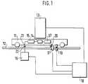
- FIG. 1shows a schematic representation of an arrangement according to the invention in cooperation with a workpiece transport carriage in a processing station
- FIG. 2shows a block diagram of the arrangement according to the invention
- FIG. 3shows a flow diagram of a method according to the invention
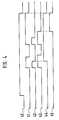
- FIG. 4shows the course of signals when processing reference values .
- Fig. 1there is a workpiece transport carriage 11, which moves on a guideway 12, in position in a processing station 13.
- the positionis reported to the workpiece transport carriage 11 by an external controller 18, for example a programmable logic controller, by means of a position sensor 19.
- the lockingIn this position, a stop pawl 20 engages in a stop device 17.
- the transport carriage 14is driven by means of an electric drive 37, not shown, which draws its energy from an accumulator 14 carried by the workpiece transport carriage 11.
- a control device 15is assigned to the accumulator 14.
- the area of the processing station 13also has a charging station 16.
- the charging station 16has charging contacts 22 which, when the workpiece transport carriage 11 is positioned in the processing station 13, are connected to the charging contacts 21 of the workpiece transport carriage 11.
- the power coupling of the charging station 16 to the accumulator 14takes place via the charging contacts 21 and 22.
- the charging contacts 21, 22are implemented using generally customary means, such as, for example, sliding contacts or extendable contacts. Another advantageous embodiment of the charging contacts 21, 22 is seen in the inductive coupling, which is not shown in the drawing.
- the external control unit 18contains control lines to the processing station 13, to the stop device 17, to the position sensor 19 and to the charging station 16.
- FIG. 2shows the charging control 15 accommodated in the workpiece transport carriage 11 with the accumulator 14 to be charged, which feeds the electric drive 37 via the power supply line 38, and the charging station 16 accommodated in the area of the processing station 13, which communicates with the external control .
- the charge control 15comprises a processor 24 which is connected to at least one memory unit 23, a device for detecting the actual charge state 33 and a device for influencing the charge process 25.
- the device for detecting the actual state of charge 33sums up the current drawn over time and the supplied charging current and thus determines an energy balance. For constant currents, it is sufficient to determine the time in which the current flows.
- a first current detector 36is coupled into the power supply lines 38 between the accumulator 14 and the electric drive 37 and a second current detector is coupled into the supply line between the power coupling and the accumulator 14, each of which only detects the current flow.
- a temperature monitoring arrangement 27can be provided which, as a safety precaution, is intended to additionally protect the accumulator 14 from being overcharged.
- the memory unit 23for example, an overwritable memory, has three memory locations in the present exemplary embodiment.
- the determined actual state of chargeis stored in a memory location.
- the other two storage locationsare used to record the reference values for the charge status of the battery.
- a minimum load Q min and / or a maximum load Q maxare provided as reference values, Q min being the load that is necessary for the workpiece transport carriage 11 to be able to move to the next processing station and Q max is the load, the full charge of the battery represents.
- Q minbeing the load that is necessary for the workpiece transport carriage 11 to be able to move to the next processing station
- Q maxis the load, the full charge of the battery represents.
- the display of the fully charged stateis intended to avoid overcharging the battery and thus its premature destruction.
- the charging stationincludes a charger 32, an electronic switch 31, a signal processing arrangement 34 and a signal adaptation arrangement 30 for communication with the external controller 18.
- the electronic switch 31serves to ensure that the charging current is only switched on and off when the workpiece transport carriage 11 is in position in the processing station 13 and the charging contacts 21, 22 are in power coupling.
- the signal processing arrangement 34contains a pulse detection arrangement 28, which is connected to the power coupling via the electronic switch 31, and a signal conditioning arrangement 29, which converts the signals transmitted via the power coupling and converted by the pulse evaluation arrangement 28 into status signals and feeds them to the signal adaptation arrangement 30.
- step 50the position sensor 19 is used to determine whether the workpiece transport carriage 11 is in position in the processing station 13. If the position is reached and the holding pawl 20 of the workpiece transport carriage 11 is locked in the stop device 17 of the processing station 13, the power coupling is implemented via the charging contacts 21, 22. If the power coupling is present, the external controller 18 outputs a start signal 40. With this start signal 40, the charging process is started by actuating the electronic switch 31.
- Step 54is implemented by processor 24.
- the processor 24compares the actual state of charge with the minimum charge Q min , which is stored in the memory unit 23. If the actual state of charge has reached the value of Q min , the external control unit 18 evaluates the actual state of charge Q min with the processing status in the processing station 13 in step 55. If the processing end has not yet been reached, the processor 24 realizes the actual Charge state of the battery 14 compared with the maximum charge Q max . In the event that the processing end has already been reached, the length of time in the charging station is not extended by extending the charging process until Q max is reached . In the event that the end of processing has been reached and / or Q max has been reached, the external control 18 withdraws the start signal 40 in step 57. The status signals are then reset to their initial state. The charging current is blocked by actuating the electronic switch 31. When the power coupling of the charging contacts 21, 22 is disconnected, the external control unit 18 receives the acknowledgment that the workpiece transport carriage 11 can leave the processing station 13.
- a start signal 40is triggered when the workpiece transport carriage 11 is positioned in the processing station 13.
- the charging currentflows to the accumulator 14 via the charging contacts 21, 22.
- the processor 24actuates the device for influencing the charging process 25, which in the present exemplary embodiment reduces the charging current to, for example, 100 mA. However, it is also conceivable to switch off the charging current entirely.
- Q minthe charging current is reduced only briefly, for example 10 ms in the present exemplary embodiment. If the charging process reaches Q max , the charging current is reduced to, for example, 100 mA for the entire remaining charging time. This is at the same time a trickle charge that does not lead to overcharging the battery.
- the limitation of the charging currentis registered by the pulse detection arrangement 28 and for this purpose a signal I from 41 is switched.
- the signal I from 41is, for example, a binary signal with the states L-0 and has a lead inverted to the charging current.
- the signal evaluation arrangement 29switches a reference signal for each stored reference value. These are also binary signals with an LO curve.
- a corresponding reference signal S min 42 and S max 43are defined for the reference values Q min and Q max when each 0-L edge of signal 1 from 41 is triggered.
- the times of the two reference signals S min and S maxare different and are fixed. They are 7 ms for S min and 15 ms for S max, for example.
- the signal evaluation arrangement 29also has the task of forming the respective status signals from the reference signals assigned to the reference values, in order to be able to draw conclusions from this actual state of charge.
- the signals I out , S min and S maxare processed in the signal processing arrangement 29 according to the following logical AND operations: I. out ⁇ S min ⁇ I. out ⁇ S Max ⁇
- the signal evaluation arrangement 29sets a binary status signal for each reference value.
- theseare the status signals MIN 44 and for the reference values Q min and Q max .
- the two switched status signals MIN and MAXremain stored until the external control 18 sets the start signal again.
- the status signals MIN and MAX switched by the signal evaluation arrangement 29are supplied to the external control 18 via the signal adaptation arrangement 30. There they are included in the process control as the signals assigned to the reference values Q min and Q max to be processed.
- the signal adaptation arrangement 30serves as electrical isolation of the charging station 16 from the external control 18 and is implemented, for example, by means of optocouplers, not shown in the drawing.
Landscapes
- Engineering & Computer Science (AREA)
- Power Engineering (AREA)
- Transportation (AREA)
- Mechanical Engineering (AREA)
- Charge And Discharge Circuits For Batteries Or The Like (AREA)
- Control Of Position, Course, Altitude, Or Attitude Of Moving Bodies (AREA)
Abstract
Description
Translated fromGermanDie Erfindung geht aus von einer Anordnung zum Laden eines Akkumulators einer Transportvorrichtung nach der Gattung des Hauptanspruchs. Weiterhin geht die Erfindung aus von einem Verfahren nach der Gattung des nebengeordneten Verfahrensanspruchs.The invention is based on an arrangement for charging an accumulator of a transport device according to the preamble of the main claim. Furthermore, the invention is based on a method according to the category of the secondary method claim.
Nach EP-A 285 527 ist eine Transferstraße bekannt, bei der sich auf einer Führungsbahn Werkstücktransportwagen von einer Bearbeitungsstation zur anderen bewegen. Dabei verfügen die Bearbeitungsstationen über jeweils eine Stoppeinrichtung zum Arretieren des Werkstücktransportwagens. Der Werkstücktransportwagen wird mittels eines Elektro-Antriebes bewegt, der seine Energie aus einem im Werkstücktransportwagen mitgeführten Akkumulator bezieht. Bei der Arretierung des Werkstücktransportwagens in der Bearbeitungsstation werden an der Unterseite des Werkstücktransportwagen angebrachte Ladekontakte, die mit dem Akkumulator elektrisch verbunden sind, mit entsprechenden Ladekontakten der in der Bearbeitungsstation angeordneten Ladestation in Verbindung gebracht. Während der Bearbeitung in der Bearbeitungsstation erfolgt dann das Nachladen des Akkumulators. Dabei sind in der genannten Vorveröffentlichung keine besonderen Mittel angegeben, um den Akkumulator kapazitätsabhängig nachzuladen.According to EP-A 285 527, a transfer line is known in which workpiece transport carriages move from one processing station to another on a guideway. The processing stations each have a stop device for locking the workpiece transport carriage. The workpiece transport trolley is moved by means of an electric drive, which draws its energy from an accumulator carried in the workpiece transport trolley. When the workpiece transport carriage is locked in the processing station, charging contacts attached to the underside of the workpiece transport carriage, which are electrically connected to the accumulator, are arranged with corresponding charging contacts in the processing station Charging station associated. The rechargeable battery is then recharged during processing in the processing station. There are no special means specified in the aforementioned prior publication for recharging the battery depending on the capacity.
Wie sich herausgestellt hat, besteht bei Transferstraßen mit Akkumulatorversorgung das Problem, daß die Bearbeitungszeiten in den Bearbeitungsstationen nicht immer ausreichen, um die erforderliche Ladung zu erreichen. Deshalb wird häufig die Verweildauer der Werkstücktransportwagen in den Bearbeitungsstationen bestimmt von der Ladezeit, die erforderlich ist, um die notwendige Ladung des Akkumulators zu erreichen. Damit verlängert die Ladezeit unnötig den Bearbeitungsdurchlauf der Werkstücktransportwagen.As has been found, the problem with transfer lines with accumulator supply is that the processing times in the processing stations are not always sufficient to achieve the required charge. Therefore, the dwell time of the workpiece transport trolleys in the processing stations is often determined by the charging time that is required to achieve the necessary charging of the accumulator. The loading time thus unnecessarily extends the machining cycle of the workpiece transport trolley.
Aus der DE 38 32 840 Al ist ein Transportsystem mit batteriebetriebenen Fahrzeugen bekannt, bei dem Ladestellen vorgesehen sind, an denen den Batterien der Fahrzeuge über Kontakte Ladestrom zugeführt wird. Sowohl die Steuerung des Fahrzeugdurchlaufs als auch die Steuerung der Batterieladung erfolgt mit Hilfe eines externen Rechners. Zur Übertragung der Daten des Ladezustandes der Batterie ist jedes Fahrzeug mit einem Datenübertragungs-Sender/-Empfänger ausgerüstet. Die Informationsübertragung des Ladezustandes der Batterie zwischen Fahrzeug und Rechner erfolgt über eine separaten Datenkanal.DE 38 32 840 A1 discloses a transport system with battery-operated vehicles, in which charging points are provided at which charging current is supplied to the batteries of the vehicles via contacts. Both the control of the vehicle flow and the control of the battery charge are carried out with the help of an external computer. Each vehicle is equipped with a data transmission transmitter / receiver to transmit the data on the state of charge of the battery. The information on the state of charge of the battery between the vehicle and the computer is transmitted via a separate data channel.
Aus der US-A- 4 347 472 ist ferner eine Vorrichtung zum Laden einer Batterie eines batteriebetriebenen Fahrzeugs bekannt, bei der die Leistungsankopplung zwischen einer externen Stromversorgungsvorrichtung und einer im Fahrzeug befindlichen Ladevorrichtung induktiv erfolgt. Über einen im Fahrzeug angeordneten Ah-zähler wird der Ladezustand der Batterie überwacht. Ein Vergleich des Ladezustandes mit einer Mindestladung ist nicht vorgesehen.From US-A-4 347 472 a device for charging a battery of a battery-powered vehicle is also known, in which the power coupling between an external Power supply device and a charging device located in the vehicle takes place inductively. The state of charge of the battery is monitored via an Ah counter arranged in the vehicle. A comparison of the state of charge with a minimum charge is not provided.
Die Erfindung mit den kennzeichnenden Merkmalen des unabhängigen Vorrichtungs- und Verfahrensanspruchs hat demgegenüber den Vorteil, daß ein bedarfsgerechtes Nachladen des Akkumulators möglich ist, wobei sich der Bedarf aus einer Energiebilanz ergibt, die die verbrauchte Energie mit mindestenes einem Referenzwert vergleicht.The invention with the characterizing features of the independent device and method claim has the advantage that it is possible to recharge the accumulator as required, the requirement resulting from an energy balance that compares the energy consumed with at least one reference value.
Mit der Erfindung kann somit erreicht werden, daß der Akkumulator des Werkstücktransportwagens stets eine Mindestladung erhält, die es ihm erlaubt, zur nächsten Ladestation zu gelangen. Damit kann sich die Ladezeit in den Bearbeitungsstationen auf das Erreichen dieser Mindestladung beschränken. Dadurch ist die Verweildauer in den Bearbeitunsgstationen nur in den Fällen von der Ladezeit des Akkumulators abhängig, wenn die Mindestladung noch nicht erreicht ist. Diese Situation wird aber äußerst selten auftreten, da im Bearbeitungsablauf auch solche Bearbeitungszeiten auftreten, die eine Ladezeit über die Mindestladung hinaus garantieren.It can thus be achieved with the invention that the accumulator of the workpiece transport carriage always receives a minimum charge which allows it to get to the next charging station. This means that the charging time in the processing stations can be limited to reaching this minimum charge. As a result, the length of time in the processing stations only depends on the charging time of the accumulator when the minimum charge has not yet been reached. However, this situation will occur extremely rarely, since processing times also occur in the processing sequence that guarantee a charging time beyond the minimum charge.
Besonders vorteilhaft ist, die mittels der im Werkstücktransportwagen untergebrachten Laderegelung geregelten Ladezustände des Akkumulators der externen Steuereinheit mitzuteilen und zur Informationsübertragung die Leistungsankopplung zwischen Akkumulator und Ladestation zu nutzen. Dies geschieht dadurch, daß für jeden Referenzwert ein Statussignal aufbereitet und der externen Steuerung zugeführt wird.It is particularly advantageous to inform the external control unit of the charge states of the accumulator, which are regulated by means of the charge control accommodated in the workpiece transport carriage, and to use the power coupling between the accumulator and the charging station for information transmission. This is done by preparing a status signal for each reference value and feeding it to the external control.
Um sowohl die Verweildauer in der Bearbeitungsstation nicht unnötig auszudehnen als auch die Akkumualtoren bei längeren Bearbeitungszeiten vor dem Überladen zu schützen, sind als Referenzwerte die Mindestladung Qmin und die Maximalladung Qmax vorgesehen.The minimum charge Qmin and the maximum charge Qmax are provided as reference values so that the time spent in the processing station is not unnecessarily extended and the accumulator doors are protected from overcharging during longer processing times.
Darüber hinaus lassen sich mit den angegebenen einfachen schaltungstechnischen Mitteln eine Vielzahl von Referenzzuständen übertragen und auswerten.In addition, a large number of reference states can be transmitted and evaluated using the simple circuitry means specified.
Durch die in den Unteransprüchen aufgeführten Maßnahmen sind vorteilhafte Weiterbildungen und Verbesserungen der Anordnung und des Verfahrens möglich.Advantageous further developments and improvements in the arrangement and the method are possible through the measures listed in the subclaims.
Schaltungstechnisch einfach läßt sich die Impulserkennung realisieren, wenn der Stromfluß anhand eines Spannungsabfalls an einem Fühlerwiderstand detektiert wird. Dabei ist es günstig, wenn das zur Impulserkennung erste Signal ein zum Verlauf des Ladestroms invertiertes Signal ist.In terms of circuitry, the pulse detection can be implemented easily if the current flow is detected on the basis of a voltage drop across a sensor resistor. It is advantageous if the first signal for pulse detection is an inverted signal for the course of the charging current.
Eine günstige Ausführung besteht weiterhin darin, die Referenzsignale jeweils durch unterschiedliche Puls/Pausenverhätlnisse zu charakterisieren.A favorable embodiment also consists in characterizing the reference signals in each case by different pulse / pause ratios.
Weiterhin gewährleistet die Erfindung, daß ein schonendes Schnelladen des Akkumulators möglich ist. Durch die Laderegelung kann bei hoher Entladung der Ladestrom hoch eingestellt werden, um schnell die Betriebsbereitschaft des Werkstücktransportwagens herzustellen. Andererseits kann bei geringer Entladung der Ladestrom niedrig eingestellt werden, um so eine Überlastung und damit eine Lebensdauerverkürzung des Akkumulators zu vermeiden. Außerdem kann gegen Ende der Aufladung der Ladestrom auf Erhaltungsladung verringert werden, so daß die Ladekapazität des Akkumulators vollständig ausgenutzt werden kann.Furthermore, the invention ensures that gentle rapid charging of the battery is possible. The charge control allows the charging current to be set high in the event of high discharge in order to quickly make the workpiece transport trolley ready for operation. On the other hand, the charge current can be set low when the discharge is low, in order to avoid overloading and thus shortening the life of the rechargeable battery. In addition, the charging current can be reduced to trickle charging towards the end of charging, so that the charging capacity of the rechargeable battery can be fully utilized.
Ein Ausführungsbeispiel der Erfindung ist in der Zeichnung dargestellt und in der nachfolgenden Beschreibung näher erläutert. Es zeigen Fig. 1 eine schematische Darstellung einer erfindungsgemäßen Anordnung im Zusammenwirken mit einem Werkstücktransportwagen in einer Bearbeitungsstation, Fig. 2 ein Blockschaltbild der erfindungsgemäßen Anordnung, Fig. 3 ein Flußdiagramm eines erfindungsgemäßen Verfahrens und Fig. 4 den Verlauf von Signalen bei der Verarbeitung von Referenzwerten.An embodiment of the invention is shown in the drawing and explained in more detail in the following description. 1 shows a schematic representation of an arrangement according to the invention in cooperation with a workpiece transport carriage in a processing station, FIG. 2 shows a block diagram of the arrangement according to the invention, FIG. 3 shows a flow diagram of a method according to the invention and FIG. 4 shows the course of signals when processing reference values .
In Fig. 1 befindet sich ein Werkstücktransportwagen 11, der sich auf einer Führungsbahn 12 bewegt, in Positon in einer Bearbeitungsstation 13. Von einer externen Steuerung 18, beispielsweise einer speicherprogrammierbaren Steuerung, erfolgt die Positionsmeldung an den Werkstücktransportwagen 11 mittels eines Positionssensors 19. Die Arretierung in dieser Position erfolgt durch Einrasten einer Anhalteklinke 20 in eine Stoppeinrichtung 17. Der Antrieb des Transportwagens 14 erfolgt mittels eines nicht näher dargestellten Elektro-Antriebes 37, welcher seine Energie aus einem vom Werkstücktransportwagen 11 mitgeführten Akkumulator 14 bezieht. Dem Akkumulator 14 ist eine Regeleinrichtung 15 zugeordnet. Der Bereich der Bearbeitungsstation 13 verfügt weiterhin über eine Ladestation 16. Die Ladestation 16 besitzt Ladekontakte 22, die bei Positionierung des Werkstücktransportwagens 11 in der Bearbeitungsstation 13 mit den Ladekontakten 21 des Werkstücktransportwagens 11 in Verbindung gebracht werden. Über die Ladekontakte 21 und 22 erfolgt die Leistungsankopplung der Ladestation 16 an den Akkumulator 14.In Fig. 1 there is a workpiece transport carriage 11, which moves on a
Die Ausführung der Ladekontake 21, 22 erfolgt mit allgemein üblichen Mitteln, wie z.B. Schleifkontakte oder ausfahrbare Kontakte. Eine weitere vorteilhafte Ausführungsform der Ladekontakte 21, 22 wird in der induktiven Kopplung gesehen, die in der Zeichnung nicht weiter ausgeführt ist.Die externe Steuereinheit 18 enthält Steuerleitungen zur Bearbeitungsstation 13, zur Stoppeinrichtung 17, zum Positionssensor 19 und zur Ladestation 16.The
In Fig. 2 ist die im Werkstücktransportwagen 11 untergebrachte Laderegelung 15 mit dem zu ladenden Akkumulator 14, der über die Stromversorgungsleitung 38 den Elektro-Antrieb 37 speist, sowie die im Bereich der Bearbeitungsstation 13 untergebrachte Ladestation 16, die mit der externen Steuerung kommuniziert, dargestellt.2 shows the
Die Laderegelung 15 umfaßt einen Prozessor 24, der mit mindestens einer Speichereinheit 23, einer Einrichtung zur Erfassung des Ist-Ladezustands 33 und einer Einrichtung zur Beeinflussung des Ladevorganges 25 in Verbindung steht.The
Die Einrichtung zur Erfassung des Ist-Ladezustands 33, beispielsweise eine Realzeiterfassunganordnung, summiert den über die Zeit entnommenen Strom und zugeführten Ladestrom auf und ermittelt somit eine Engergiebilanz. Bei Konstantströmen ist es ausreichend, jeweils die Zeit zu ermitteln, in der der Strom fließt. Dazu ist in den Stromversorgungsleitungen 38 zwischen Akkumulator 14 und Elektro-Antrieb 37 ein erster Stromdetektor 36 und in die Versorgungsleitung zwischen der Leistungsankopplung und dem Akkumulator 14 ein zweiter Stromdetektor eingekoppelt, die jeweils lediglich den Stromfluß detektieren.The device for detecting the actual state of
Aus der Energiebilanz läßt sich die Ladezeit nach der Formel
- Tl
- die Ladezeit,
- Ic
- der entnommene Strom,
- Il
- der Ladestrom,
- E
- die Entladezeit und
- η
- der Wirkungsgrad des verwendeten Akkumulators
- Tl
- the charging time,
- Ic
- the current drawn,
- Il
- the charging current,
- E
- the discharge time and
- η
- the efficiency of the accumulator used
Wird mit einer variablen Ladestromstärke geladen und ist der Stromverbrauch des Elektro-Antriebs 37 unterschiedlich, werden an Stelle der beiden Stromdetektoren 36, 37 jeweils Stromfühler eingesetzt. Der Prozessor ermittelt dann anhand der beiden Summen den Ist-Ladezustand.If charging is carried out with a variable charging current and the current consumption of the
Es ist aber genauso denkbar, den Ist-Ladezustand mittels Messung der momentanen Akkuspannung zu ermitteln.However, it is also conceivable to determine the actual state of charge by measuring the current battery voltage.
Außerdem kann eine Temperaturüberwachungsanordnung 27 vorgesehen werden, die als Sicherheitsvorkehrung den Akkumulator 14 vor einem Überladen zusätzlich schützen soll.In addition, a
Die Speichereinheit 23 beispielsweise, ein überschreibbarer Speicher, verfügt im vorliegenden Ausführungsbeispiel über drei Speicherplätze. In einem Speicherplatz wird der ermittelte Ist-Ladezustand abgelegt. Die beiden weiteren Speicherplätze dienen zur Aufnahme der Referenzwerte für den Ladezustand des Akkumulators.The
Im vorliegenden Ausführungsbeispiel sind als Referenzwerte eine Mindestladung Qmin und/oder eine Maximal ladung Qmax vorgesehen, wobei Qmin die Ladung ist, die notwendig ist, damit der Werkstücktransportwagen 11 sich bis zur nächsten Bearbeitungsstation bewegen kann, sowie Qmax die Ladung ist, die den Volladezustand des Akkumulators repräsentiert. Mit der Anzeige des Volladezustandes soll ein Überladen des Akkumulators und damit seine frühzeitige Zerstörung vermieden werden.In the present exemplary embodiment, a minimum load Qmin and / or a maximum load Qmax are provided as reference values, Qmin being the load that is necessary for the workpiece transport carriage 11 to be able to move to the next processing station and Qmax is the load, the full charge of the battery represents. The display of the fully charged state is intended to avoid overcharging the battery and thus its premature destruction.
Die Ladestation enthält ein Ladegerät 32, einen elektronischen Schalter 31, eine Signalverarbeitungsanordnung 34 und eine Signalanpassungsanordnung 30 zur Kommunikation mit der externen Steuerung 18.The charging station includes a
Der elektronische Schalter 31 dient dazu, daß der Ladestrom nur zugeschaltet und abgeschaltet wird, wenn sich der Werkstücktransportwagen 11 in Position in der Bearbeitungsstation 13 und die Ladekontakte 21, 22 in Leistungsankopplung befinden.The
Die Signalverarbeitungsanordnung 34 enthält eine Impulserkenungsanordnung 28, die über den elektronischen Schalter 31 mit der Leistungsankopplung in Verbindung steht, und eine Signalaufbereitungsanordnung 29, die die über die Leistungsankopplung übertragenen und von der Impulsauswerteanordnung 28 umgesetzten Signale in Status signale umwandelt und der Signalanpassungsanordnung 30 zuführt.The
In Fig. 3 ist zum besseren Verständnis der Wirkungsweise der Erfindung ein Flußdiagramm des Verfahrens zum Laden des Akkumulators 14 dargestellt. Zunächst wird im Schritt 50 mittels des Positionssensor 19 festgestellt, ob sich der Werkstücktransportwagen 11 in Position in der Bearbeitungsstation 13 befindet. Ist die Position erreicht und die Halteklinke 20 des Werkstücktransportwagens 11 in der Stoppeinrichtung 17 der Bearbeitungsstation 13 arretiert, wird die Leistungsankopplung über die Ladekontakte 21, 22 realisiert. Liegt die Leistungsankopplung vor, wird von der externen Steuerung 18 eine Startsignal 40 ausgegeben. Mit diesem Startsignal 40 wird gleichzeitig der Ladevorgang durch Betätigung des elektronischen Schalters 31 in Gang gesetzt.A flow diagram of the method for charging the accumulator 14 is shown in FIG. 3 for a better understanding of the mode of operation of the invention. First, in
Der Schritt 54 wird vom Prozessor 24 realisiert. Dabei vergleicht der Prozessor 24 den Ist-Ladezustand mit der Mindestladung Qmin, die in der Speichereinheit 23 abgelegt ist. Hat der Ist-Ladezustand den Wert von Qmin erreicht, erfolgt im Schritt 55 von der externen Steuereinheit 18 die Auswertung des Ist-Ladezustandes Qmin mit dem Bearbeitungsstatus in der Bearbeitungsstation 13. Ist das Bearbeitungsende noch nicht erreicht, wird vom Prozessor 24 der Ist-Ladezustand des Akkumulators 14 mit der Maximalladung Qmax verglichen. Für den Fall, daß das Bearbeitungsende bereits erreicht ist, wird die Verweildauer in der Ladestation nicht durch das Ausdehnen des Ladevorganges bis zum Erreichen von Qmax ausgedehnt. In den Fällen Bearbeitungsende erreicht und/oder Qmax erreicht, wird im Schritt 57 von der externen Steuerung 18 das Startsignal 40 zurückgenommen. Daraufhin werden die Statussignale in ihren Ausgangszustand zurückgesetzt. Der Ladestrom wird durch Betätigung des elektronischen Schalters 31 gesperrt. Mit dem Trennen der Leistungsankopplung der Ladekontakte 21, 22 liegt der externen Steuereinheit 18 die Quittung vor, daß der Werkstücktransportwagen 11 die Bearbeitungsstation 13 verlassen kann.
Mit Fig. 4 sei nachfolgend der Signalverlauf verdeutlicht. Wie bereits erläutert, wird bei Positionierung des Werkstücktransportwagens 11 in der Bearbeitungsstation 13 ein Startsignal 40 getriggert. Über die Ladekontakte 21, 22 fließt der Ladestrom zum Akkumulator 14.The signal curve is illustrated below with FIG. 4. As already explained, a
Sobald der Ist-Ladezustand den Wert der Mindestladung Qmin erreicht hat, wird vom Prozessor 24 die Einrichtung zur Beeinflussung des Ladevorganges 25 betätigt, welche im vorliegenden Ausführungsbeispiel den Ladestrom auf beispielsweise 100 mA reduziert. Es ist aber auch denkbar, den Ladestrom ganz abzuschalten. Beim Erreichen von Qmin wird der Ladestrom nur kurzzeitig, im vorliegenden Ausführungsbeispiel beispielsweise 10 ms reduziert. Erreicht der Ladevorgang Qmax wird der Ladestrom für die gesamte verbleibende Ladezeit auf beispielsweise 100 mA reduziert. Damit erfolgt gleichzeitig eine Erhaltungsladung, die nicht zum Überladen des Akkumulators führt.As soon as the actual state of charge has reached the value of the minimum charge Qmin , the
Die Begrenzung des Ladestromes wird von der Impulserkennungsanordnung 28 registriert und dazu ein Signal Iaus 41 geschaltet. Das Signal Iaus 41 ist beispielsweise ein binäres Signal mit den Zuständen L-0 und hat einen zum Ladestrom invertierten Vorlauf.The limitation of the charging current is registered by the
Zu jeder 0-L-Flanke des Signals Iaus 41 wird von der Signalauswerteanordnung 29 für jeden gespeicherten Referenzwert jeweils ein Referenzsignal geschaltet. Es handelt sich dabei ebenfalls um binäre Signale mit L-O-Verlauf. Im vorliegenden Ausführungsbeispiel werden zu den Referenzwerten Qmin und Qmax bei Triggerung jeder 0-L-Flanke des Signals 1 aus 41 ein entsprechendes Referenzsignal Smin 42 und Smax 43 definiert. Die Zeiten der beiden Referenzsignale Smin und Smax sind unterschiedlich und sind fest eingestellt. Sie betragen hierbei für Smin beispielsweise 7 ms und für Smax beispielsweise 15 ms.For each 0-L edge of the signal Ifrom 41, the signal evaluation arrangement 29 switches a reference signal for each stored reference value. These are also binary signals with an LO curve. In the present exemplary embodiment, a corresponding
Die Signalauswerteanordnung 29 hat weiterhin die Aufgabe, aus den den Referenzwerten zugeordneten Referenzsignalen die jeweiligen Statussignale zu bilden, um daraus den Rückschluß auf den tatsächlichen Ladezustand zu ziehen. Dazu erfolgt in der Signalaufbereitungsanordnung 29 die Verarbeitung der Signale Iaus, Smin und Smax nach folgenden logischen UND-Verknüpfungen:

Anhand dieser logischen Verknüpfungen wird von der Signalauswerteanordnung 29 für jeden Referenzwert ein binäres Statussignal gesetzt. Im vorliegenden Ausführungsbeispiel sind das für die Referenzwerte Qmin und Qmax die Statussignale MIN 44 und. MAX 45. Die beiden geschalteten Statussignale MIN und MAX bleiben gespeichert bis die externe Steuerung 18 das Startsignal neu setzt.On the basis of these logic operations, the signal evaluation arrangement 29 sets a binary status signal for each reference value. In the present exemplary embodiment, these are the status signals MIN 44 and for the reference values Qmin and Qmax .
Die von der Signalauswerteanordnung 29 geschaltetenen Statussignale MIN und MAX werden über die Signalanpassungsanordnung 30 der externen Steuerung 18 zugeführt. Dort werden sie als die den zu verarbeitenden Referenzwerten Qmin und Qmax zugeordneten Signale in die Prozeßsteuerung einbezogen. Die Signalanpassungsanordnung 30 dient als galvanische Trennung der Ladestation 16 zur externen Steuerung 18 und ist beispielsweise mittels in der Zeichnung nicht dargestellten Optokopplern realisiert.The status signals MIN and MAX switched by the signal evaluation arrangement 29 are supplied to the
Claims (19)
- Arrangement for charging a battery (14) of a transport device (11) with a dedicated electric drive, in particular in a self-propelled workpiece transport vehicle given the presence of transfer pathways, having an external control unit (18), an external charging station (16) and a charging control system (15) with a processer (24), in which arrangement the transport device (11) is moved, controlled by the external control unit (18), from one station to the other, and a power coupling (21, 22) to the external charging station (16) is provided for the battery (14), the charging control system (15) being provided in the transport device (11), and the processor (24) being connected to at least one memory unit (23) containing reference values, one device for detecting the actual charging state (33) and one device (25) for influencing the charging operation, and the processor (24) comparing the actual charging state with a minimum charge Qmin and a maximum charge Qmax as reference values, and the device (25) for influencing the charging operation being capable of acting on the charging current in such a way that the battery (14) acquires at least the minimum charge Qmin, characterized in that the charging station (16) has a signal processing arrangement (34) with a pulse recognition arrangement (28) connected to the power coupling (21, 22), in that the pulse recognition arrangement (28) detects the action, exerted by the device (25) for influencing the charging operation, on the charging operation and respectively triggers a signal (41) when an influence is exerted on the charging operation for the minimum charge Qmin and for the maximum charge Qmax, in that the signal processing arrangement (34) contains means (29, 30) which in relation to each signal triggering of the pulse recognition arrangement (28) switches a first reference signal (42) for the minimum charge Qmin and a second reference signal (43) for the maximum charge Qmax, and in that by means of a combination of the signal (41) with the respective reference signal (42, 43) a first status signal (44) is formed for the minimum charge Qmin and a second status signal (45) is formed for the maximum charge Qmax, which are transmitted to the external control unit (18).
- Arrangement according to Claim 1, characterized in that the first status signal (44) is formed by the logic AND combination Iout ^


- Arrangement according to Claim 1, characterized in that the device (25) for influencing the charging operation is a charging current controller which limits or switches off the charging current.
- Arrangement according to Claim 1, characterized in that the first signal (41) is a signal Iout which is inverted relative to the characteristic of the charging current.
- Arrangement according to Claim 1, characterized in that the reference signals (43, 44) are respectively characterized by different mark-to-space ratios.
- Arrangement according to Claim 5, characterized in that flip-flops are used to define the mark-to-space ratios.
- Arrangement according to Claim 1, characterized in that a signal-matching arrangement (30) is provided for coupling to the external control unit (18).
- Arrangement according to Claim 6, characterized in that as a signal-matching arrangement (30) an electrical isolation, preferably a transmission by means of optocouplers, is provided.
- Arrangement according to Claim 1, characterized in that the at least one memory unit (23) is an over-writable memory.
- Arrangement according to Claim 9, characterized in that the actual charging states are stored in the memory unit (23).
- Arrangement according to Claim 1, characterized in that the device for detecting the actual charging state (33) is a real-time detecting arrangement which sums up the current drawn over time via a first current detector (36), arranged between the battery (14) and the electric drive (37), and sums up the charging current fed over time via a second current detector (36), arranged between the battery (14) and charging contacts (21), and forms the actual state therefrom.
- Arrangement according to Claim 11, characterized in that the first and the second current detectors (36) and (26) are current sensors in each case.
- Method for charging a battery (14) of a transport device (11) with a dedicated electric drive, in particular for workpiece transport vehicles given the presence of transfer pathways, in which the transport device (11) is moved, controlled by an external control unit (18), from one station to the other, and the battery (14) is charged via a power coupling (21, 22) by an external charging station (16), it being the case that a processor (24) in the transport device (11) carries out a comparison of the actual charging state with a minimum charge Qmin and a maximum charge Qmax as reference values and this result is used by the processor (24) to act on the charging operation in such a way that the battery (14) acquires at least one charge corresponding to one of the reference values, in particular the minimum charge Qmin required to reach the next charging station, or at most the prescribed maximum charge Qmax, characterized in that the effect on the charging operation is detected via the power coupling (21, 22), in that the charging station (16) respectively forms a corresponding status signal (44, 45) for the minimum charge Qmin and the maximum charge Qmax, in that the status signals (44, 45) are fed to the external control unit (18), in that the control unit (18) evaluates the charging state of the battery (14) communicated by the status signal (44, 45) and evaluates a start signal (40) representing the processing status, and in that the transport device (11) is released as a function of the end of processing and at the earliest when the minimum charging state is reached.
- Method according to Claim 13, characterized in that to influence the power coupling use is made of the current flowing via the power coupling, this current being limited or switched off.
- Method according to Claim 13, characterized in that the actual charging state is determined via an energy balance which sums up the current drawn over time and thereafter the charging time is determined according to the formula
 Tl is the charging time,Ic is the current drawn,Il is the charging current,E is the discharging time, andη is the efficiency of the battery.
 - Method according to Claim 13, characterized in that on each occasion that the power coupling is influenced a signal (41) is triggered which is inverted relative to the charging current, in that for each triggering of the first signal (41) a reference signal is respectively connected for each reference value, and in that the status signals assigned to the respective reference signals are formed by combining the first signal (41) with one reference signal in each case.
- Method according to Claim 13, characterized in that the reference signals Smin (43) and Smax (44) are assigned to the minimum charge Qmin and/or the maximum charge Qmax.
- Method according to Claim 13, characterized in that a logic AND combination of the first signal (41) with the negated reference signals Smin (43) and Smax (44) is used to form the status signals.
- Method according to Claim 18, characterized in that the reference signals Smin (43) and/or Smax (44) are respectively characterized by different mark-to-space ratios.


Applications Claiming Priority (3)
| Application Number | Priority Date | Filing Date | Title |
|---|---|---|---|
| DE4014696 | 1990-05-08 | ||
| DE4014696ADE4014696C3 (en) | 1990-05-08 | 1990-05-08 | Arrangement and method for charging an accumulator of a transport device with its own electric drive |
| PCT/DE1991/000287WO1991017599A1 (en) | 1990-05-08 | 1991-04-05 | Device and process for charging the battery of a self-powered electric transport vehicle |
Publications (2)
| Publication Number | Publication Date |
|---|---|
| EP0482138A1 EP0482138A1 (en) | 1992-04-29 |
| EP0482138B1true EP0482138B1 (en) | 1996-09-04 |
Family
ID=6405929
Family Applications (1)
| Application Number | Title | Priority Date | Filing Date |
|---|---|---|---|
| EP91906722AExpired - LifetimeEP0482138B1 (en) | 1990-05-08 | 1991-04-05 | Device and process for charging the battery of a self-powered electric transport vehicle |
Country Status (5)
| Country | Link |
|---|---|
| US (1) | US5298849A (en) |
| EP (1) | EP0482138B1 (en) |
| JP (1) | JP3053864B2 (en) |
| DE (2) | DE4014696C3 (en) |
| WO (1) | WO1991017599A1 (en) |
Families Citing this family (17)
| Publication number | Priority date | Publication date | Assignee | Title |
|---|---|---|---|---|
| US5467006A (en)* | 1992-12-21 | 1995-11-14 | Ford Motor Company | Energy transfer device and method |
| DE4312572A1 (en)* | 1993-04-17 | 1994-10-20 | Licentia Gmbh | Charging monitoring device for an electric battery |
| US6114833A (en)* | 1995-04-14 | 2000-09-05 | Lester Electrical Of Nebraska, Inc. | Monitoring and controlling system for battery and battery charger |
| US6863988B2 (en) | 1996-09-23 | 2005-03-08 | Bp Corporation North America Inc. | Oxygen scavenging monolayer bottles |
| ATE209999T1 (en)* | 1998-09-12 | 2001-12-15 | Urs Bucher | WORKPIECE CARRIER WITH STORAGE DRIVE |
| AT500328B1 (en)* | 2002-02-07 | 2010-03-15 | Elin Ebg Traction Gmbh | VEHICLE WITH AN ELECTRIC DRIVE AND METHOD FOR OPERATING SUCH A VEHICLE |
| JP4884945B2 (en)* | 2006-11-30 | 2012-02-29 | 三菱重工業株式会社 | Charging state prediction program, overhead line-less traffic system and charging method thereof |
| JP4568736B2 (en)* | 2007-02-27 | 2010-10-27 | 三菱重工業株式会社 | Overhead-less transportation system and charging method thereof |
| US8307967B2 (en)* | 2007-07-04 | 2012-11-13 | Satyajit Patwardhan | Widely deployable charging system for vehicles |
| DE102007051972B4 (en) | 2007-10-31 | 2012-08-09 | Audi Ag | Arrangement for mounting vehicles, in particular motor vehicles |
| DE102008039955A1 (en)* | 2008-08-27 | 2010-03-04 | Bayerische Motoren Werke Aktiengesellschaft | Charging station for energy storage unit of electric vehicle, has activation unit switched based on driving and/or moving condition of vehicle, and charging plug that is non-insertable in socket, when vehicle is not in parking condition |
| DE102009017556A1 (en)* | 2009-04-17 | 2010-10-21 | Bär, Ralf, Dipl.-Ing. | Method for operating an assembly plant and driverless, mobile assembly and / or material handling unit therefor |
| MX2012012454A (en) | 2010-04-26 | 2013-09-13 | Proterra Inc | Systems and methods for automatic connection and charging of an electric vehicle at a charging station. |
| WO2013153659A1 (en)* | 2012-04-12 | 2013-10-17 | 株式会社日立製作所 | Vehicle control system |
| CN103231899B (en)* | 2013-05-06 | 2015-04-15 | 哈尔滨工业大学 | Automatic guiding trolley for file transfer |
| CN107757408B (en)* | 2017-10-31 | 2020-07-31 | 苏州易信安工业技术有限公司 | Management method, device and system for battery charging room of electric vehicle |
| US12296705B2 (en)* | 2021-09-28 | 2025-05-13 | Iontra Inc | Systems and methods for on-board EV charger and regenerative braking |
Citations (2)
| Publication number | Priority date | Publication date | Assignee | Title |
|---|---|---|---|---|
| DE3312600A1 (en)* | 1983-04-08 | 1984-10-11 | Ceag Licht- Und Stromversorgungstechnik Gmbh, 4770 Soest | ARRANGEMENT FOR CAPACITY-RELATED CHARGING OF A BATTERY |
| US4885523A (en)* | 1988-03-15 | 1989-12-05 | Norand Corporation | Battery conditioning system having communication with battery parameter memory means in conjunction with battery conditioning |
Family Cites Families (12)
| Publication number | Priority date | Publication date | Assignee | Title |
|---|---|---|---|---|
| DE2405198A1 (en) | 1973-02-15 | 1974-08-22 | Oscar Dr Ing Bossi | BATTERY OPERATED TRANSPORT SYSTEM, ESPECIALLY FOR PUBLIC TRANSPORT |
| US3955657A (en)* | 1974-02-15 | 1976-05-11 | Oscar Bossi | Electric traction transportation system with storage battery powered vehicles and fast recharge at the vehicle stops |
| FR2443686A1 (en)* | 1978-12-07 | 1980-07-04 | Accumulateurs Fixes | METHOD AND DEVICE FOR MONITORING THE STATE OF CHARGE OF A BATTERY |
| US4347472A (en)* | 1980-10-20 | 1982-08-31 | Lemelson Jerome H | Apparatus and method for charging a battery in a vehicle |
| US4672280A (en)* | 1983-12-27 | 1987-06-09 | Casio Computer Co., Ltd. | Mobile robot calling system |
| US4580081A (en)* | 1984-09-07 | 1986-04-01 | Outboard Marine Corporation | Computer controlled motor vehicle battery circuit |
| FR2611557B1 (en)* | 1987-03-04 | 1994-02-25 | Teissier Etienne | FREE TRANSFER MACHINE WITH INDEPENDENT AND MOTORIZED TROLLEYS |
| DE8808873U1 (en)* | 1988-07-11 | 1988-11-17 | Eisenmann Fördertechnik KG, 71088 Holzgerlingen | Driverless transport vehicle |
| DE3832840A1 (en)* | 1988-09-28 | 1990-03-29 | Ind Automation Mikroelektronik | Transport system with battery-operated vehicles |
| EP0425044B1 (en)* | 1989-10-25 | 1994-08-10 | Koninklijke Philips Electronics N.V. | Device for charging a battery |
| US5049802A (en)* | 1990-03-01 | 1991-09-17 | Caterpillar Industrial Inc. | Charging system for a vehicle |
| US5119011A (en)* | 1990-08-08 | 1992-06-02 | General Electric Company | Battery state of charge indicator |
- 1990
- 1990-05-08DEDE4014696Apatent/DE4014696C3/ennot_activeExpired - Fee Related
- 1991
- 1991-04-05JPJP3506733Apatent/JP3053864B2/ennot_activeExpired - Lifetime
- 1991-04-05DEDE59108137Tpatent/DE59108137D1/ennot_activeExpired - Fee Related
- 1991-04-05USUS07/773,901patent/US5298849A/ennot_activeExpired - Fee Related
- 1991-04-05EPEP91906722Apatent/EP0482138B1/ennot_activeExpired - Lifetime
- 1991-04-05WOPCT/DE1991/000287patent/WO1991017599A1/enactiveIP Right Grant
Patent Citations (2)
| Publication number | Priority date | Publication date | Assignee | Title |
|---|---|---|---|---|
| DE3312600A1 (en)* | 1983-04-08 | 1984-10-11 | Ceag Licht- Und Stromversorgungstechnik Gmbh, 4770 Soest | ARRANGEMENT FOR CAPACITY-RELATED CHARGING OF A BATTERY |
| US4885523A (en)* | 1988-03-15 | 1989-12-05 | Norand Corporation | Battery conditioning system having communication with battery parameter memory means in conjunction with battery conditioning |
Also Published As
| Publication number | Publication date |
|---|---|
| JPH04507189A (en) | 1992-12-10 |
| EP0482138A1 (en) | 1992-04-29 |
| US5298849A (en) | 1994-03-29 |
| DE4014696C2 (en) | 1994-04-21 |
| WO1991017599A1 (en) | 1991-11-14 |
| DE59108137D1 (en) | 1996-10-10 |
| DE4014696C3 (en) | 2003-07-17 |
| JP3053864B2 (en) | 2000-06-19 |
| DE4014696A1 (en) | 1991-11-21 |
Similar Documents
| Publication | Publication Date | Title |
|---|---|---|
| EP0482138B1 (en) | Device and process for charging the battery of a self-powered electric transport vehicle | |
| EP2625763B1 (en) | Method and charging station for electrically charging an electrical energy store | |
| EP2419990B1 (en) | Extended battery diagnosis for traction batteries | |
| DE10121772A1 (en) | System for automatically charging the battery of a remote control transmitter for use in a vehicle security system | |
| DE19832628A1 (en) | Long range transponder arrangement e.g. for vehicle identification, using HF pump circuit to transfer operating power from vehicle supply when in transmit mode | |
| DE102006042603A1 (en) | loader | |
| EP2673161B1 (en) | Method for monitoring the use of an electrochemical energy accumulator in a motor vehicle and motor vehicle | |
| DE102011107055A1 (en) | Method for controlling and monitoring of mode of discharge and/or charge of e.g. lithium-polymer battery of industrial lorry, involves starting discharge and/or charging modes of battery when minimum voltage is applied to power connection | |
| DE102020007348A1 (en) | Method for operating an electric vehicle and electric vehicle | |
| DE102011122629A1 (en) | unlocking | |
| DE102019128079A1 (en) | Door security system, method of operating a door security system and means of transport | |
| DE19934708B4 (en) | Portable remote control unit | |
| EP1630925B1 (en) | Device for charging at least two batteries | |
| EP3199397A1 (en) | Method for loading a traction battery of at least partially electrically driven vehicles and loading station | |
| EP3659202B1 (en) | Bypass switch on an accumulator | |
| EP2828946B1 (en) | Storage means for electrical energy and holding apparatus for at least one storage means for a vehicle which can be electrically driven | |
| EP4434137A1 (en) | Method for charging or discharging an exchangeable energy store by means of an electrical device and system comprising an exchangeable energy store and an electrical device for carrying out the method | |
| DE4231970A1 (en) | Storage battery charging circuit - has transformer and rectifier with protective switch as relay or power semiconductor between charging circuit output and at least one of the charging pole connections | |
| DE19817423C2 (en) | Method and device for recognizing a battery pack | |
| EP0288013A1 (en) | Apparatus for charging a battery | |
| DE102010026130B4 (en) | Connection device for connection to an electrical network, vehicle with this and connection method for connection to an electrical network | |
| DE102021104086A1 (en) | Safety device for at least one light source, transmission device for light, detection device, vehicle with at least one detection device and method for operating at least one light source | |
| EP3975308A1 (en) | Method for protecting a battery | |
| EP0960040B1 (en) | Automobile security device | |
| DE10100888A1 (en) | Controller for on-board electrical system has direct voltage converter that can produce one of several direct voltages (14V, 42V) and output connection for currently selected output voltage |
Legal Events
| Date | Code | Title | Description |
|---|---|---|---|
| PUAI | Public reference made under article 153(3) epc to a published international application that has entered the european phase | Free format text:ORIGINAL CODE: 0009012 | |
| 17P | Request for examination filed | Effective date:19911115 | |
| AK | Designated contracting states | Kind code of ref document:A1 Designated state(s):AT CH DE ES FR GB IT LI SE | |
| 17Q | First examination report despatched | Effective date:19950329 | |
| GRAG | Despatch of communication of intention to grant | Free format text:ORIGINAL CODE: EPIDOS AGRA | |
| GRAH | Despatch of communication of intention to grant a patent | Free format text:ORIGINAL CODE: EPIDOS IGRA | |
| RBV | Designated contracting states (corrected) | Designated state(s):CH DE FR GB IT LI | |
| GRAH | Despatch of communication of intention to grant a patent | Free format text:ORIGINAL CODE: EPIDOS IGRA | |
| GRAA | (expected) grant | Free format text:ORIGINAL CODE: 0009210 | |
| AK | Designated contracting states | Kind code of ref document:B1 Designated state(s):CH DE FR GB IT LI | |
| REG | Reference to a national code | Ref country code:CH Ref legal event code:NV Representative=s name:SCINTILLA AG, DIREKTION | |
| ET | Fr: translation filed | ||
| REF | Corresponds to: | Ref document number:59108137 Country of ref document:DE Date of ref document:19961010 | |
| ITF | It: translation for a ep patent filed | ||
| GBT | Gb: translation of ep patent filed (gb section 77(6)(a)/1977) | Effective date:19961106 | |
| PLBE | No opposition filed within time limit | Free format text:ORIGINAL CODE: 0009261 | |
| STAA | Information on the status of an ep patent application or granted ep patent | Free format text:STATUS: NO OPPOSITION FILED WITHIN TIME LIMIT | |
| 26N | No opposition filed | ||
| PGFP | Annual fee paid to national office [announced via postgrant information from national office to epo] | Ref country code:DE Payment date:20010625 Year of fee payment:11 | |
| REG | Reference to a national code | Ref country code:GB Ref legal event code:IF02 | |
| PGFP | Annual fee paid to national office [announced via postgrant information from national office to epo] | Ref country code:FR Payment date:20020417 Year of fee payment:12 | |
| PGFP | Annual fee paid to national office [announced via postgrant information from national office to epo] | Ref country code:CH Payment date:20020422 Year of fee payment:12 | |
| PGFP | Annual fee paid to national office [announced via postgrant information from national office to epo] | Ref country code:GB Payment date:20020425 Year of fee payment:12 | |
| PG25 | Lapsed in a contracting state [announced via postgrant information from national office to epo] | Ref country code:DE Free format text:LAPSE BECAUSE OF NON-PAYMENT OF DUE FEES Effective date:20021101 | |
| PG25 | Lapsed in a contracting state [announced via postgrant information from national office to epo] | Ref country code:GB Free format text:LAPSE BECAUSE OF NON-PAYMENT OF DUE FEES Effective date:20030405 | |
| PG25 | Lapsed in a contracting state [announced via postgrant information from national office to epo] | Ref country code:LI Free format text:LAPSE BECAUSE OF NON-PAYMENT OF DUE FEES Effective date:20030430 Ref country code:CH Free format text:LAPSE BECAUSE OF NON-PAYMENT OF DUE FEES Effective date:20030430 | |
| GBPC | Gb: european patent ceased through non-payment of renewal fee | Effective date:20030405 | |
| REG | Reference to a national code | Ref country code:CH Ref legal event code:PL | |
| PG25 | Lapsed in a contracting state [announced via postgrant information from national office to epo] | Ref country code:FR Free format text:LAPSE BECAUSE OF NON-PAYMENT OF DUE FEES Effective date:20031231 | |
| REG | Reference to a national code | Ref country code:FR Ref legal event code:ST | |
| PG25 | Lapsed in a contracting state [announced via postgrant information from national office to epo] | Ref country code:IT Free format text:LAPSE BECAUSE OF NON-PAYMENT OF DUE FEES;WARNING: LAPSES OF ITALIAN PATENTS WITH EFFECTIVE DATE BEFORE 2007 MAY HAVE OCCURRED AT ANY TIME BEFORE 2007. THE CORRECT EFFECTIVE DATE MAY BE DIFFERENT FROM THE ONE RECORDED. Effective date:20050405 |