EP0481157B1 - Device for supporting the slats of a slat support - Google Patents
Device for supporting the slats of a slat supportDownload PDFInfo
- Publication number
- EP0481157B1 EP0481157B1EP90870191AEP90870191AEP0481157B1EP 0481157 B1EP0481157 B1EP 0481157B1EP 90870191 AEP90870191 AEP 90870191AEP 90870191 AEP90870191 AEP 90870191AEP 0481157 B1EP0481157 B1EP 0481157B1
- Authority
- EP
- European Patent Office
- Prior art keywords
- rod
- slats
- spring
- installation according
- chamber
- Prior art date
- Legal status (The legal status is an assumption and is not a legal conclusion. Google has not performed a legal analysis and makes no representation as to the accuracy of the status listed.)
- Expired - Lifetime
Links
- 239000012528membraneSubstances0.000claimsdescription13
- 238000009434installationMethods0.000claimsdescription10
- 238000005096rolling processMethods0.000claims1
- 239000007788liquidSubstances0.000description4
- 229920001971elastomerPolymers0.000description3
- 230000006835compressionEffects0.000description1
- 238000007906compressionMethods0.000description1
- 230000000994depressogenic effectEffects0.000description1
- 238000006073displacement reactionMethods0.000description1
- 239000000806elastomerSubstances0.000description1
- 230000007935neutral effectEffects0.000description1
Images


Classifications
- A—HUMAN NECESSITIES
- A47—FURNITURE; DOMESTIC ARTICLES OR APPLIANCES; COFFEE MILLS; SPICE MILLS; SUCTION CLEANERS IN GENERAL
- A47C—CHAIRS; SOFAS; BEDS
- A47C23/00—Spring mattresses with rigid frame or forming part of the bedstead, e.g. box springs; Divan bases; Slatted bed bases
- A47C23/06—Spring mattresses with rigid frame or forming part of the bedstead, e.g. box springs; Divan bases; Slatted bed bases using wooden springs, e.g. of slat type ; Slatted bed bases
- A47C23/062—Slat supports
- A47C23/063—Slat supports by elastic means, e.g. coil springs
- A—HUMAN NECESSITIES
- A47—FURNITURE; DOMESTIC ARTICLES OR APPLIANCES; COFFEE MILLS; SPICE MILLS; SUCTION CLEANERS IN GENERAL
- A47C—CHAIRS; SOFAS; BEDS
- A47C23/00—Spring mattresses with rigid frame or forming part of the bedstead, e.g. box springs; Divan bases; Slatted bed bases
- A47C23/06—Spring mattresses with rigid frame or forming part of the bedstead, e.g. box springs; Divan bases; Slatted bed bases using wooden springs, e.g. of slat type ; Slatted bed bases
- A47C23/062—Slat supports
- A47C23/065—Slat supports by fluid means
Definitions
- This inventionrelates to an installation making it possible to support the slats of a box spring disposed with respect to the frame of a bed, each slat being supported by a rod which is directly under the influence of a hydraulically or pneumatically actuated element, which element can be moved inside a room, all rooms being interconnected according to the principle of communicating vessels.
- the central part of the slatted basewill sink completely to the lowest point when the user lies on it and this regardless of its position. This is due to the fact that the body is heaviest in its central part.
- German patent DE-B-1 260 092describes a slatted base in which each slat is supported on a piston which itself is supported on a roll-up membrane supported by the liquid contained in a cylinder. All the cylinders communicate with each other. This structure does not prevent in any way that extreme deviations or situations appear between close or even distant slats because nothing makes it possible to attenuate these extreme position deviations between neighboring or substantially neighboring slats, which creates uncomfortable situations for the user.
- the inventionaims to remedy this drawback and various others and to prescribe an installation which substantially improves the elastic support of such a slatted base.
- the hydraulically or pneumatically actuated elementconsists in a piston whose connecting rod corresponds to the aforementioned rod.
- the hydraulically or pneumatically movable elementis a membrane to which the aforementioned link is connected.
- the above-mentioned movable elementis a roll-up membrane which acts on the rod guided in the aforementioned chamber.
- FIG. 1is a theoretical representation of the problem posed when a determined weight is supported on the slatted base.
- FIG. 2illustrates the distribution of the pressure on a slatted base not equipped with a counter-pressure spring.
- FIG. 3illustrates the same distribution of pressure when back pressure springs are used.
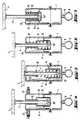
- FIG. 4shows an embodiment with a wound membrane, in which an adjustable air pressure is used as a counter-pressure spring.
- Figures 5, 6 and 7show an embodiment in which use is made of a wound membrane and showing the back pressure spring in three successive positions.
- Figures 8 and 9show two possible arrangements of a back pressure spring between a fixed element and a movable element.
- Figure 10shows a possibility of arrangement of a rubber spring.
- FIG. 11represents a possibility of arrangement of an air spring.
- Figure 12shows a front view of an arrangement of a torsion spring.
- FIG. 13represents a side view of an arrangement of the torsion spring according to FIG. 12.
- Figure 14shows a front view of an arrangement of a leaf spring.
- FIG. 15represents a side view of an arrangement of the leaf spring according to FIG. 13.
- the envisaged movement of the slats which form the slatted baseis slowed down by diaphragming, in a manner known per se, the outlet orifices of the chambers or cylinders.
- downward pressureis created so that the slats on which pressure is exerted are completely in their position the lowest.
- the other slats which do not support weight or pressureare positioned in the highest position. This situation develops on the assumption that, for a neutral rest position, all the rooms are half full.
- FIG. 2is a representation of a slatted base in which all the slats 4 rests on rods 5 which are either fully inserted where the body offers its heaviest weight, either found in their highest position, where no pressure or insignificant pressure is exerted on the slats.
- Figure 3is illustrated schematically the example of the case in which the body 3 of the user is supported on slats 4 which are themselves supported on rods 5 which are subjected to the action of a spring back pressure according to one or other of the provisions described below.
- An ideal distribution of the slatsis created here and there is a clearly visible intermediate position of these slats between a position in which they should normally have been fully inserted and a second position in which they could have been in the highest position.
- the way in which a counter-pressure spring can be inserted into a slatted base according to the inventionis described with reference to a large number of examples.
- a rolled membrane 24is applied in each of the chambers 6.
- the rolled membraneshave a very flexible structure so that part of the rolled membrane rolls up and takes place between the wall inside of the chamber 6 and the outer wall of a piston 25 which is fixed to the base of the link 5.
- the piston 25is guided relative to the chamber 6 by means of a small cylindrical part 26 which forms part of the chamber 6 , at the top and inside.
- useis made as a counter-pressure spring of the hydraulic or pneumatic pressure adjustable in the chamber 6 above the roll-up membrane 24.
- adjustable valvesfor example small ball valves 27.
- FIGS. 5, 6 and 7which represent a single and same structure in three different active positions, use is made as a counter-pressure spring, of a spiral spring 28 which is arranged around rod 5 and can be compressed between the upper inner part of a chamber 6 and the internal bottom 25 ′ of the piston 25.
- the passage orifices 29are provided at the top in each of the chambers 6 of the embodiment according to FIGS. 5, 6 and 7.
- FIG. 6shows an intermediate position in which the volume of the space 7 and the spiral spring 28 is or will be subjected to a start of compression between the bottom 25 'of the piston 25 and the upper edge of the chamber 6.
- Figure 7shows how the space 7 reaches maximum volume while the back pressure spring 28 is fully depressed.
- FIG. 8The embodiments according to Figures 8 and 9 show special arrangements of a pressure spring (Figure 8) and a tension spring (Figure 9).
- the counter-pressure springis gripped between a stud 31 which moves with the link 5, until the stud 31 is fixed on a lateral arm 5 ′ of the link 5.
- the upper part of the counter spring pressure 30fits in a cylindrical housing 32 which must be considered as a fixed element relative to the frame of the bed or the furniture.
- the embodiment according to Figure 9comprises an element 33 which is fixed relative to the frame of the bed.
- This elementhas at its base and laterally an arm 33 ′ equipped with a small pin 34 around which one end of the tension spring 35 is gripped.
- the spring 35also ends with a hook 36 to which is welded a small pin 36 'which can be moved along the chamber 37 of the housing 38.
- the cylindrical housing 38forms a whole with the link 5 which is itself connected to the batten 4. When the batten 4 is pressed down at the same time as the link 5, the housing 38 will descend over a distance which corresponds approximately to the length of the slot 37.
- the counter-pressure springis formed by a cylinder 43.
- a piston 44is then connected to the connecting rod 5, a piston whose base is fixedly connected to the lateral arm 5 ′ of the link 5.
- an air springis used to act as a counter-pressure spring.
- the embodiment according to Figures 12 and 13is the same.
- the link 5here forms a whole with a plate 44 which can be moved in a guide 45 which must be considered as a fixed element relative to the frame of the bed.
- a torsion spring 46which presses by its arm 46 'against a small pin 47 which is fixed in the plate 44.
- FIGS. 14 and 15it is also possible to make use of a leaf spring as the counter-pressure spring as shown in FIGS. 14 and 15.
- the back pressure springscan be locally suppressed or modified.
Landscapes
- Mattresses And Other Support Structures For Chairs And Beds (AREA)
- Invalid Beds And Related Equipment (AREA)
- Fluid-Damping Devices (AREA)
- Blinds (AREA)
- Auxiliary Devices For And Details Of Packaging Control (AREA)
- Accessories Of Cameras (AREA)
- Actuator (AREA)
- Filling Or Discharging Of Gas Storage Vessels (AREA)
- Bedding Items (AREA)
- Special Chairs (AREA)
- Chain Conveyers (AREA)
- Biological Treatment Of Waste Water (AREA)
Abstract
Description
Translated fromFrenchCette invention concerne une installation permettant de soutenir les lattes d'un sommier disposé par rapport au châssis d'un lit, chaque latte étant soutenue par une tige qui se trouve directement sous l'influence d'un élément actionné hydrauliquement ou pneumatiquement, lequel élément peut être déplacé à l'intérieur d'une chambre, toutes les chambres étant reliées entre elles selon le principe des vases communicants.This invention relates to an installation making it possible to support the slats of a box spring disposed with respect to the frame of a bed, each slat being supported by a rod which is directly under the influence of a hydraulically or pneumatically actuated element, which element can be moved inside a room, all rooms being interconnected according to the principle of communicating vessels.
Un exemple d'une forme de réalisation de l'espèce est constitué par le brevet BE-A- 806.241, de même que par la demande de brevet PCT WO 89/01749 ainsi que par le brevet GB-A- 2.178.307. Suivant ces documents, plusieurs cylindres ou chambres remplissant une fonction technique équivalente sont disposés des deux côtés du sommier à lattes et ces cylindres ou leurs éqivalents sont reliés entre eux par une conduite de telle façon que les divers cylindres ou chambres fonctionnent comme des vases communicants.An example of an embodiment of the present case is constituted by patent BE-A-806,241, as well as by PCT patent application WO 89/01749 as well as by patent GB-A- 2,178,307. According to these documents, several cylinders or chambers fulfilling an equivalent technical function are arranged on both sides of the slatted base and these cylinders or their equivalents are connected to one another by a pipe so that the various cylinders or chambers function as communicating vessels.
Dans une forme de réalisation de l'espèce visée, la partie centrale du sommier à lattes s'enfoncera complètement jusqu'au point le plus bas lorsque l'utilisateur se couche sur celui-ci et celà indépendamment de sa position. Ceci est dû au fait que le corps est le plus lourd en sa partie centrale.In one embodiment of the target species, the central part of the slatted base will sink completely to the lowest point when the user lies on it and this regardless of its position. This is due to the fact that the body is heaviest in its central part.
Enfin le brevet allemand DE-B-1 260 092 décrit un sommier à lattes dans lequel chaque latte prend appui sur un piston prenant lui-même appui sur une membrane déroulable soutenue par le liquide contenu dans un cylindre. Tous les cylindres communiquent entre eux. Cette structure n'empêche en rien que des écarts ou situations extrêmes apparaissent entre des lattes rapprochées ou même éloignées car rien ne permet d'attenuer ces écarts de positions extrêmes entre des lattes voisines ou sensiblement voisines, ce qui crée des situations inconfortables pour l'utilisateur.Finally, German patent DE-B-1 260 092 describes a slatted base in which each slat is supported on a piston which itself is supported on a roll-up membrane supported by the liquid contained in a cylinder. All the cylinders communicate with each other. This structure does not prevent in any way that extreme deviations or situations appear between close or even distant slats because nothing makes it possible to attenuate these extreme position deviations between neighboring or substantially neighboring slats, which creates uncomfortable situations for the user.
L'invention a pour but de remédier à cet inconvénient et à divers autres et de prescrire une installation qui améliore sensiblement le support élastique d'un tel sommier à lattes.The invention aims to remedy this drawback and various others and to prescribe an installation which substantially improves the elastic support of such a slatted base.
Pour réaliser ceci conformément à l'invention. au moins une partie des éléments susdits, qui sont chacun déplacés sous l'action de la pression exercée, sont soumis à l'action d'un ressort de contre-pression.To do this according to the invention. at least a part of the aforementioned elements, which are each moved under the action of the pressure exerted, are subjected to the action of a counter-pressure spring.
Dans une première forme de réalisation possible, l'élément actionné hydrauliquement ou pneumatiquement consiste en un piston dont la bielle correspond à la tige précitée.In a first possible embodiment, the hydraulically or pneumatically actuated element consists in a piston whose connecting rod corresponds to the aforementioned rod.
Dans une autre forme de réalisation possible, l'élément déplaçable hydrauliquement ou pneumatiquement est une membrane à laquelle la biellette précitée est reliée.In another possible embodiment, the hydraulically or pneumatically movable element is a membrane to which the aforementioned link is connected.
Dans une forme de réalisation remarquable appliquée de préférence, l'élément déplaçable précité est une membrane enroulable qui agit sur la tige guidée dans la chambre précitée.In a remarkable embodiment preferably applied, the above-mentioned movable element is a roll-up membrane which acts on the rod guided in the aforementioned chamber.
D'autres modes particuliers de réalisation selon l'invention sont indiqués dans les revendications 4,6,7.Other particular embodiments according to the invention are indicated in
D'autres détails et avantages de l'invention ressortiront de la description donnée ci-après d'une installation permettant de soutenir les lattes d'un sommier à lattes selon l'invention. Cette description n'est donnée qu'à titre d'exemple et ne limite pas la portée de l'invention. Les notations de référence se rapportent aux figures ci-jointes.Other details and advantages of the invention will emerge from the description given below of an installation making it possible to support the slats of a slatted base according to the invention. This description is given by way of example only and does not limit the scope of the invention. The reference notations refer to the attached figures.
La figure 1 est une représentation théorique du problème posé lorsqu'un poids déterminé prend appui sur le sommier à lattes.FIG. 1 is a theoretical representation of the problem posed when a determined weight is supported on the slatted base.
La figure 2 illustre la répartition de la pression sur un sommier à lattes non équipé d'un ressort de contre-pression.FIG. 2 illustrates the distribution of the pressure on a slatted base not equipped with a counter-pressure spring.
La figure 3 illustre la même répartition d'une pression lorsqu'il est fait usage de ressorts de contre-pression.Figure 3 illustrates the same distribution of pressure when back pressure springs are used.
La figure 4 représente une forme d'exécution avec membrane enroulée, dans laquelle on fait appel à une pression réglable de l'air en tant que ressort de contre-pression.FIG. 4 shows an embodiment with a wound membrane, in which an adjustable air pressure is used as a counter-pressure spring.
Les Figures 5, 6 et 7 représentent une forme d'exécution dans laquelle on fait usage d'une membrane enroulée et montrant le ressort de contre-pression dans trois positions successives.Figures 5, 6 and 7 show an embodiment in which use is made of a wound membrane and showing the back pressure spring in three successive positions.
Les figures 8 et 9 représentent deux dispositions possibles d'un ressort de contre-pression entre un élément fixe et un élément mobile.Figures 8 and 9 show two possible arrangements of a back pressure spring between a fixed element and a movable element.
La figure 10 représente une possibilité de disposition d'un ressort en caoutchouc.Figure 10 shows a possibility of arrangement of a rubber spring.
La figure 11 représente une possibilité de disposition d'un ressort pneumatique.FIG. 11 represents a possibility of arrangement of an air spring.
La figure 12 représente une vue de face d'une disposition d'un ressort de torsion.Figure 12 shows a front view of an arrangement of a torsion spring.
La figure 13 représente une vue latérale d'une disposition du ressort de torsion selon la figure 12.FIG. 13 represents a side view of an arrangement of the torsion spring according to FIG. 12.
La figure 14 représente une vue de face d'une disposition d'un ressort à lame.Figure 14 shows a front view of an arrangement of a leaf spring.
La figure 15 représente une vue latérale d'une disposition du ressort à lame suivant la figure 13.FIG. 15 represents a side view of an arrangement of the leaf spring according to FIG. 13.
En se référant en premier lieu aux figures 1 et 2, on constate que le mouvement ascendant et descendant d'un sommier à lattes est causé par la disposition d'un poids 1 sur ces lattes. Ceci provoque une circulation interne du liquide dans les cylindres ou chambres qui sera décrite plus loin en détail. En raison du fait que le liquide n'est pas compressible, un déplacement du liquide doit avoir lieu. Si celui-ci n'a pas lieu, aucun déplacement n'est possible. Au passage, il doit être souligné que dans la description et les revendications, le terme "chambre" sera utilisé parce que ceci désigne un support qui peut aussi bien être hydraulique que pneumatique.Referring first to Figures 1 and 2, we see that the upward and downward movement of a slatted base is caused by the provision of a
Le déplacement envisagé des lattes qui forment le sommier à lattes est freiné en diaphragmant, de manière connue en soi, les orifices de sortie des chambres ou cylindres. Par le mouvement linéaire d'un certain nombre de lattes appartenant au sommier à lattes, tel que représenté à la figure 1, une pression vers le bas est créée de telle sorte que les lattes sur lesquelles une pression est exercée se trouvent complètement dans leur position la plus basse. Les autres lattes qui ne supportent pas de poids ni de pression viennent se positionner dans la position la plus élevée. Cette situation se développe dans la supposition que, pour une position de repos neutre, toutes les chambres sont à moitié remplies.The envisaged movement of the slats which form the slatted base is slowed down by diaphragming, in a manner known per se, the outlet orifices of the chambers or cylinders. By the linear movement of a number of slats belonging to the slatted base, as shown in Figure 1, downward pressure is created so that the slats on which pressure is exerted are completely in their position the lowest. The other slats which do not support weight or pressure are positioned in the highest position. This situation develops on the assumption that, for a neutral rest position, all the rooms are half full.
Une situation analogue, dérivée de cette situation théorique, est représentée à la figure 2. A la figure 2, la partie la plus lourde du corps 3 repose au milieu du sommier à lattes, milieu considéré dans le sens de la longueur. Dans cette figure schématique, le sommier à lattes est représenté par la référence 2. La figure 2 est une représentation d'un sommier à lattes dans lequel toutes les lattes 4 s'appuie sur des biellettes 5 qui sont soit complètement enfoncées là où le corps offre son poids le plus lourd, soit se trouvent dans leur position la plus élevée, là où aucune pression ou une pression insignifiante est exercée sur les lattes.A similar situation, derived from this theoretical situation, is represented in FIG. 2. In FIG. 2, the heaviest part of the
A la figure 3 est illustré schématiquement l'exemple du cas dans lequel le corps 3 de l'utilisateur s'appuie sur des lattes 4 qui s'appuient elles-mêmes sur des biellettes 5 qui sont soumises à l'action d'un ressort de contre-pression selon l'une ou l'autre des dispositions décrites ci-après. Il se crée ici une répartition idéale des lattes et il existe une position intermédiaire bien visible de ces lattes entre une position dans laquelle elles auraient normalement dû être complètement enfoncées et une seconde position dans laquelle elles auraient pu se trouver dans la position la plus élevée. La manière dont peut être inséré un ressort de contre-pression dans un sommier à lattes selon l'invention est décrite en se référant à un grand nombre d'exemples.In Figure 3 is illustrated schematically the example of the case in which the
Selon les figures 4 à 7 incluse, on applique, dans chacune des chambres 6, une membrane enroulée 24. Les membranes enroulées ont une structure fort souple de telle sorte qu'une partie de la membrane enroulée s'enroule et se déroule entre la paroi intérieure de la chambre 6 et la paroi extérieure d'un piston 25 qui est fixé à la base de la biellette 5. Le piston 25 est guidé par rapport à la chambre 6 grâce à une petite partie cylindrique 26 qui fait partie de la chambre 6, à la partie supérieure et à l'intérieur de celle-ci.According to FIGS. 4 to 7 inclusive, a rolled
Ici également on remarque les étranglements 8 et les conduites 9 qui relient entre elles toutes les chambres appartenant à une même série.Here also we notice the
Dans la forme d'exécution selon la figure 4, on fait usage en tant que ressort de contre-pression de la pression hydraulique ou pneumatique réglable dans la chambre 6 au-dessus de la membrane enroulable 24. Pour régler cette pression, on fait usage de vannes réglables, par exemple de petites vannes à billes 27.In the embodiment according to FIG. 4, use is made as a counter-pressure spring of the hydraulic or pneumatic pressure adjustable in the
Dans la forme d'exécution suivant les figures 5, 6 et 7, qui représentent une seule et même structure dans trois positions actives différentes, on fait usage en tant que ressort de contre-pression, d'un ressort spiralé 28 qui est disposé autour de la biellette 5 et peut être comprimé entre la partie intérieure supérieure d'une chambre 6 et le fond interne 25' du piston 25. Les orifices de passage 29 sont prévus à la partie supérieure dans chacune des chambres 6 de la forme d'exécution suivant les figures 5, 6 et 7.In the embodiment according to FIGS. 5, 6 and 7, which represent a single and same structure in three different active positions, use is made as a counter-pressure spring, of a
Dans la figure 5, l'espace 7 dans la chambre 6 déterminée par la membrane enroulable 24, est réduit à son volume minimum.In FIG. 5, the space 7 in the
La figure 6 montre une position intermédiaire dans laquelle le volume de l'espace 7 et le ressort spiralé 28 est ou va être soumis à un début de compression entre le fond 25' du piston 25 et le bord supérieur de la chambre 6.FIG. 6 shows an intermediate position in which the volume of the space 7 and the
La figure 7 montre de quelle manière l'espace 7 atteint un volume maximum tandis que le ressort de contre-pression 28 est complètement enfoncé.Figure 7 shows how the space 7 reaches maximum volume while the
Les formes d'exécution selon les figures 8 et 9 montrent des dispositions particulières d'un ressort de pression (figure 8) et d'un ressort de traction (figure 9). Selon la figure 8, le ressort de contre-pression est saisi entre un téton 31 qui se déplace avec la biellette 5, attendu que le téton 31 est fixé sur un bras latéral 5' de la biellette 5. La partie supérieure du ressort de contre-pression 30 s'adapte dans un logement cylindrique 32 qui doit être considéré comme un élément fixe par rapport au châssis du lit ou du meuble.The embodiments according to Figures 8 and 9 show special arrangements of a pressure spring (Figure 8) and a tension spring (Figure 9). According to FIG. 8, the counter-pressure spring is gripped between a
La forme d'exécution suivant la figure 9 comporte un élément 33 qui est fixe par rapport au châssis du lit. Cet élément présente à sa base et latéralement un bras 33' équipé d'une petite broche 34 autour de laquelle une extrémité du ressort de traction 35 est agrippée. A la partie supérieure, le ressort 35 se termine également par un crochet 36 auquel est soudée une petite broche 36' qui peut être déplacée le long de la chambre 37 du logement 38. Le logement cylindrique 38 forme un tout avec la biellette 5 qui est elle-même reliée à la latte 4. Lorsque la latte 4 est enfoncée vers le bas en même temps que la biellette 5, le logement 38 descendra sur une distance qui correspond environ à la longueur de la fente 37.The embodiment according to Figure 9 comprises an
Dans la forme d'exécution suivant la figure 10, il est monté d'une manière sommaire comment il est possible,entre un élément fixe 39 (fixe par rapport au châssis du lit) et une biellette 5, de mettre sous tension un ressort de contre-pression, constitué de préférence par du caoutchouc ou un autre élastomère, et représenté par la référence 40, entre les tétons 41 et 42 appartenant respectivement à l'élément fixe 39 et à la biellette 5.In the embodiment according to Figure 10, it is roughly mounted how it is possible, between a fixed element 39 (fixed relative to the bed frame) and a
Dans la forme d'exécution selon la figure 11, le ressort de contre-pression est formé par un cylindre 43. Un piston 44 est alors relié à la biellette 5, piston dont la base est reliée de manière fixe au bras latéral 5' de la biellette 5. Dans cette forme d'exécution, il est fait appel à un ressort pneumatique pour faire office de ressort de contre-pression.In the embodiment according to FIG. 11, the counter-pressure spring is formed by a
La forme d'exécution selon les figures 12 et 13 est la même. La biellette 5 forme ici un tout avec une plaque 44 qui peut être déplacée dans un guidage 45 qui doit être considéré comme un élément fixe par rapport au châssis du lit. Sur le guidage 45 est fixé un ressort de torsion 46 qui appuie par son bras 46' contre une petite broche 47 qui est fixée dans la plaque 44.The embodiment according to Figures 12 and 13 is the same. The
Enfin, on peut également faire usage en tant que ressort de contre-pression d'un ressort à lame tel que ceci a été représenté aux figures 14 et 15. Le ressort de contre-pression formé par le ressort à lame 48 monté entre les petites broches 49, d'une part, et une butée 50, d'autre part, laquelle est fixée sur une pièce de support 51 qui est fixe par rapport au châssis du lit,exerce une pression sur la plaque 52 qui est reliée de manière fixe à la biellette 5.Finally, it is also possible to make use of a leaf spring as the counter-pressure spring as shown in FIGS. 14 and 15. The counter-pressure spring formed by the
Il doit être entendu que la dans la description qui est donnée ci-dessus aucune distinction n'est faite entre les divers appuis d'une latte appartenant à un sommier à lattes. La présence d'un ressort de contre-pression dans tous les éléments qui sont soumis à la pression exercée sur les lattes n'est pas une nécessité absolue.It should be understood that in the description given above, no distinction is made between the various supports of a slat belonging to a slatted base. The presence of a counterpressure spring in all the elements which are subjected to the pressure exerted on the slats is not an absolute necessity.
Pour diverses raisons d'ordre médical, les ressorts de contre-pression peuvent être localement supprimés ou modifiés.For various medical reasons, the back pressure springs can be locally suppressed or modified.
Claims (7)
- Installation making it possible to support the slats (4) of a bed base arranged with respect to the frame of a bed, each slat (4) being supported by a rod (5) which is directly under the influence of a hydraulically or pneumatically actuated element, which element may be moved inside a chamber (6), all the chambers (6) being joined together according to the communicating vessels principle, characterized in that at least one part of the abovementioned elements, which are each moved under the action of the pressure exerted, are subjected to the action of an opposing-pressure spring.
- Installation according to Claim 1, characterized in that the hydraulically or pneumatically actuated element consists of a piston (25) the connecting rod of which corresponds to the aforementioned rod (5).
- Installation according to Claim 1, characterized in that the hydraulically or pneumatically movable element is a membrane (10) with which the connecting rod (5) interacts.
- Installation according to Claim 3, characterized in that the said membrane (10) acts directly on the said rod (5).
- Installation according to Claim 1, characterized in that the hydraulically or pneumatically movable element is a rolling membrane (24) which acts on the rod (5) guided in the chamber (6).
- Installation according to Claim 2, characterized in that the aforementioned opposing-pressure spring is a coil spring (28) wound around the rod (5).
- Installation according to Claim 2, characterized in that the opposing-pressure spring is mounted outside the aforementioned chamber (6) between the aforementioned rod (5) and the frame of the bed, on an element fixed to the latter.
Priority Applications (8)
| Application Number | Priority Date | Filing Date | Title |
|---|---|---|---|
| DE69008726TDE69008726T2 (en) | 1990-10-16 | 1990-10-16 | Support device for the slats of a slatted frame. |
| EP90870191AEP0481157B1 (en) | 1990-10-16 | 1990-10-16 | Device for supporting the slats of a slat support |
| ES90870191TES2051506T3 (en) | 1990-10-16 | 1990-10-16 | INSTALLATION TO SUPPORT THE LAMAS OF A SOMIER DE LAMAS. |
| AT9090870191TATE105159T1 (en) | 1990-10-16 | 1990-10-16 | SUPPORTING DEVICE FOR THE SLATS OF A SLATTED FRAME. |
| DK90870191.5TDK0481157T3 (en) | 1990-10-16 | 1990-10-16 | Device for supporting the slats in a slat bed base |
| NO914023ANO303614B1 (en) | 1990-10-16 | 1991-10-14 | Device for supporting the ribs in a bed base |
| CA002053535ACA2053535C (en) | 1990-10-16 | 1991-10-16 | Slat support system for slat spring |
| US07/916,805US5265290A (en) | 1990-10-16 | 1992-07-22 | Device for supporting the slats of a slatted base |
Applications Claiming Priority (1)
| Application Number | Priority Date | Filing Date | Title |
|---|---|---|---|
| EP90870191AEP0481157B1 (en) | 1990-10-16 | 1990-10-16 | Device for supporting the slats of a slat support |
Publications (2)
| Publication Number | Publication Date |
|---|---|
| EP0481157A1 EP0481157A1 (en) | 1992-04-22 |
| EP0481157B1true EP0481157B1 (en) | 1994-05-04 |
Family
ID=8206086
Family Applications (1)
| Application Number | Title | Priority Date | Filing Date |
|---|---|---|---|
| EP90870191AExpired - LifetimeEP0481157B1 (en) | 1990-10-16 | 1990-10-16 | Device for supporting the slats of a slat support |
Country Status (8)
| Country | Link |
|---|---|
| US (1) | US5265290A (en) |
| EP (1) | EP0481157B1 (en) |
| AT (1) | ATE105159T1 (en) |
| CA (1) | CA2053535C (en) |
| DE (1) | DE69008726T2 (en) |
| DK (1) | DK0481157T3 (en) |
| ES (1) | ES2051506T3 (en) |
| NO (1) | NO303614B1 (en) |
Families Citing this family (17)
| Publication number | Priority date | Publication date | Assignee | Title |
|---|---|---|---|---|
| DE19811854B4 (en)* | 1998-03-18 | 2007-04-12 | Woodstock Company Langegger Breitfuss Oeg | Pad for lying or sitting |
| DE29714024U1 (en)* | 1997-08-06 | 1997-12-18 | Recticel Internationale Bettsy | Bearing body for the resilient mounting of strips of a bed frame |
| BE1012330A3 (en) | 1998-12-10 | 2000-09-05 | Complete Investments Ltd | Sprung structure for supporting the slats of a slatted base in relation to a frame |
| FR2791238A1 (en)* | 1999-03-22 | 2000-09-29 | Michel Michaux | ROUND BED SUMMER WITH LARGE VERTICAL MOVEMENT |
| AU5384900A (en)* | 1999-07-02 | 2001-01-22 | Fabio Camponovo | Modular device for supporting the human body |
| DE20000477U1 (en) | 2000-01-13 | 2000-03-23 | Weber Erhard | Coupled wave band suspension for bed frames and mattresses |
| US20040074008A1 (en)* | 2002-06-22 | 2004-04-22 | Wendell Martens | Memory foam mattress system |
| WO2005039360A1 (en) | 2003-10-27 | 2005-05-06 | Dorsoo | Body support |
| DE102005016198A1 (en)* | 2005-04-11 | 2006-10-12 | Heldmaier, Uwe, Dr. | Laying and sitting device e.g. for sitting device divided into different segments, has framework where several setters are provided having trailer and heading and framework is a plate, or perforated tile with end piece has one side hinged |
| DE202005011767U1 (en)* | 2005-05-26 | 2005-10-20 | Thomas Hilfen Hilbeg Gmbh & Co. Kg | Device for intermittent moving of areas of sleeping surface, assembled of lifting element and electrically activated elastic part |
| US7552491B2 (en)* | 2005-11-10 | 2009-06-30 | Voelker Ag | Lying surface for a bed, in particular a healthcare and/or hospital bed |
| EP2101613B1 (en)* | 2006-12-09 | 2015-08-12 | TheraTorr Medical, Inc. | A device for supporting a user's body |
| KR100947374B1 (en)* | 2008-09-26 | 2010-03-15 | 주식회사 코스피 | A medical bed |
| KR101148737B1 (en)* | 2011-08-30 | 2012-05-24 | 정원섭 | Mattress of body pressure dispersion with a cushion add-on |
| US9504336B2 (en)* | 2013-02-13 | 2016-11-29 | Jon Dodd | Configurable bed |
| US20140283302A1 (en)* | 2013-03-23 | 2014-09-25 | Uwe Horstmann | Device for the insertion in bedsteads, bedding boxes or bed frames for use as a lying surface with a mattress on top of it for primarily a single person |
| DE202020004054U1 (en) | 2019-09-28 | 2020-10-14 | Manfred Tödter | Alternating pressure bed |
Family Cites Families (7)
| Publication number | Priority date | Publication date | Assignee | Title |
|---|---|---|---|---|
| DE1260092B (en)* | 1963-12-23 | 1968-02-01 | Dr Med Ludwig Zwehl | Seating and reclining furniture |
| FR2407692A1 (en)* | 1977-11-02 | 1979-06-01 | Ind Transformation Bois | Mattress with balanced weight distribution - consists of case with reinforced sides, and slats supported by springs, elastomeric blocks or inflatable compartments |
| DE2832584C2 (en)* | 1978-07-25 | 1983-09-29 | Ludwig Dr.med. 3000 Hannover Zwehl | Furniture for sunbathing, in particular hospital beds |
| ATE8569T1 (en)* | 1980-04-11 | 1984-08-15 | Gordon Douglas Griffin | BED OR LIKE. |
| NL8200401A (en)* | 1982-02-03 | 1983-09-01 | Auping Bv | BODY SUPPORT. |
| DE3246983A1 (en)* | 1982-12-18 | 1984-06-20 | Arthur 6803 Edingen-Neckarhausen Lieberknecht | Under-mattress with transverse beams and resilient connecting pieces |
| DE3728408A1 (en)* | 1987-08-26 | 1989-03-09 | Oswald Kurt | BED |
- 1990
- 1990-10-16DEDE69008726Tpatent/DE69008726T2/ennot_activeExpired - Fee Related
- 1990-10-16EPEP90870191Apatent/EP0481157B1/ennot_activeExpired - Lifetime
- 1990-10-16DKDK90870191.5Tpatent/DK0481157T3/enactive
- 1990-10-16ESES90870191Tpatent/ES2051506T3/ennot_activeExpired - Lifetime
- 1990-10-16ATAT9090870191Tpatent/ATE105159T1/ennot_activeIP Right Cessation
- 1991
- 1991-10-14NONO914023Apatent/NO303614B1/ennot_activeIP Right Cessation
- 1991-10-16CACA002053535Apatent/CA2053535C/ennot_activeExpired - Fee Related
- 1992
- 1992-07-22USUS07/916,805patent/US5265290A/ennot_activeExpired - Lifetime
Also Published As
| Publication number | Publication date |
|---|---|
| NO914023L (en) | 1992-04-21 |
| DK0481157T3 (en) | 1994-07-11 |
| ATE105159T1 (en) | 1994-05-15 |
| US5265290A (en) | 1993-11-30 |
| DE69008726D1 (en) | 1994-06-09 |
| NO303614B1 (en) | 1998-08-10 |
| CA2053535A1 (en) | 1992-04-17 |
| EP0481157A1 (en) | 1992-04-22 |
| ES2051506T3 (en) | 1994-06-16 |
| CA2053535C (en) | 2000-01-18 |
| NO914023D0 (en) | 1991-10-14 |
| DE69008726T2 (en) | 1994-10-27 |
Similar Documents
| Publication | Publication Date | Title |
|---|---|---|
| EP0481157B1 (en) | Device for supporting the slats of a slat support | |
| FR2818121A1 (en) | ARTICULATED BILLOT OPERATING TABLE | |
| FR2564927A1 (en) | CYLINDER | |
| CH625689A5 (en) | ||
| EP0774223B1 (en) | Deformable undermattress with ergonomic shape | |
| FR2557440A3 (en) | ADJUSTABLE ARMCHAIR | |
| EP1372433B1 (en) | Bed equipped with a back elevator | |
| FR2519955A2 (en) | Pressure operated tool support - has inflatable bellows with one end fixed and other carrying tool | |
| FR2483774A1 (en) | Body support e.g. operating table - has body laid on flexible top sheet supported by rollers which are driven by reciprocating lower bearing plate | |
| FR2659840A1 (en) | Support for hanging objects, especially from a picture rail | |
| FR2848082A1 (en) | Mounting for attaching slats to bed frame has sleeves which fit over ends of the slats and are connected by curved spring to bracket which fits on to frame | |
| FR2656204A1 (en) | FOLDING BASE FOR SOFA BEDS AND THE LIKE. | |
| CH625017A5 (en) | ||
| FR2711521A1 (en) | Patient bed. | |
| FR2538070A1 (en) | OPERATING APPARATUS FOR A VACUUM-OPERATED LIQUID CONVEYOR, PREFERABLY A VACUUM SEWER SYSTEM | |
| EP1053704A1 (en) | Tilt mechanism and covertible sofa-bed structure with such a mechanism | |
| EP1260249A1 (en) | Exercise apparatus with pneumatic cylinder | |
| FR2937246A1 (en) | HYGIENIC TETINE | |
| FR2528933A1 (en) | TWO-POSITION FLUID CONTROL VALVE | |
| FR2868674A1 (en) | Bedding assembly raising device, has connecting rods controlled by electromechanical jack and articulated on fixed lower frame and on movable upper frame, respectively, to articulate frames with respect to each other | |
| FR2547184A3 (en) | Chair or armchair which can be converted into a bed | |
| FR2818519A1 (en) | Mattress has integral pillow supported e.g. by internal springs which are longer than those supporting remainder of mattress | |
| FR2674802A1 (en) | ADJUSTING DEVICE FOR A MATTRESS SUPPORT MEMBER. | |
| EP2873349B1 (en) | Suspension device and bed base provided with such a device | |
| EP1273248A1 (en) | Slated bed-base with variable firmness |
Legal Events
| Date | Code | Title | Description |
|---|---|---|---|
| PUAI | Public reference made under article 153(3) epc to a published international application that has entered the european phase | Free format text:ORIGINAL CODE: 0009012 | |
| 17P | Request for examination filed | Effective date:19901102 | |
| AK | Designated contracting states | Kind code of ref document:A1 Designated state(s):AT BE CH DE DK ES FR GB IT LI NL SE | |
| 17Q | First examination report despatched | Effective date:19920710 | |
| RAP1 | Party data changed (applicant data changed or rights of an application transferred) | Owner name:COMPLETE INVESTMENTS LIMITED | |
| GRAA | (expected) grant | Free format text:ORIGINAL CODE: 0009210 | |
| AK | Designated contracting states | Kind code of ref document:B1 Designated state(s):AT BE CH DE DK ES FR GB IT LI NL SE | |
| REF | Corresponds to: | Ref document number:105159 Country of ref document:AT Date of ref document:19940515 Kind code of ref document:T | |
| GBT | Gb: translation of ep patent filed (gb section 77(6)(a)/1977) | Effective date:19940506 | |
| REF | Corresponds to: | Ref document number:69008726 Country of ref document:DE Date of ref document:19940609 | |
| REG | Reference to a national code | Ref country code:ES Ref legal event code:FG2A Ref document number:2051506 Country of ref document:ES Kind code of ref document:T3 | |
| ITF | It: translation for a ep patent filed | ||
| REG | Reference to a national code | Ref country code:DK Ref legal event code:T3 | |
| EAL | Se: european patent in force in sweden | Ref document number:90870191.5 | |
| PLBE | No opposition filed within time limit | Free format text:ORIGINAL CODE: 0009261 | |
| STAA | Information on the status of an ep patent application or granted ep patent | Free format text:STATUS: NO OPPOSITION FILED WITHIN TIME LIMIT | |
| 26N | No opposition filed | ||
| REG | Reference to a national code | Ref country code:GB Ref legal event code:IF02 | |
| REG | Reference to a national code | Ref country code:CH Ref legal event code:PFA Owner name:COMPLETE INVESTMENTS LIMITED Free format text:COMPLETE INVESTMENTS LIMITED#12, HERBERT PLACE#DUBLIN (IE) -TRANSFER TO- COMPLETE INVESTMENTS LIMITED#12, HERBERT PLACE#DUBLIN (IE) | |
| PGFP | Annual fee paid to national office [announced via postgrant information from national office to epo] | Ref country code:DE Payment date:20081022 Year of fee payment:19 Ref country code:CH Payment date:20081015 Year of fee payment:19 Ref country code:DK Payment date:20081015 Year of fee payment:19 | |
| PGFP | Annual fee paid to national office [announced via postgrant information from national office to epo] | Ref country code:AT Payment date:20081015 Year of fee payment:19 Ref country code:ES Payment date:20081027 Year of fee payment:19 | |
| PGFP | Annual fee paid to national office [announced via postgrant information from national office to epo] | Ref country code:IT Payment date:20081025 Year of fee payment:19 Ref country code:SE Payment date:20081014 Year of fee payment:19 | |
| PGFP | Annual fee paid to national office [announced via postgrant information from national office to epo] | Ref country code:GB Payment date:20081021 Year of fee payment:19 | |
| PGFP | Annual fee paid to national office [announced via postgrant information from national office to epo] | Ref country code:BE Payment date:20090814 Year of fee payment:20 Ref country code:NL Payment date:20090930 Year of fee payment:20 | |
| PGFP | Annual fee paid to national office [announced via postgrant information from national office to epo] | Ref country code:FR Payment date:20091016 Year of fee payment:20 | |
| REG | Reference to a national code | Ref country code:CH Ref legal event code:PL | |
| EUG | Se: european patent has lapsed | ||
| REG | Reference to a national code | Ref country code:DK Ref legal event code:EBP | |
| PG25 | Lapsed in a contracting state [announced via postgrant information from national office to epo] | Ref country code:DE Free format text:LAPSE BECAUSE OF NON-PAYMENT OF DUE FEES Effective date:20100501 | |
| PG25 | Lapsed in a contracting state [announced via postgrant information from national office to epo] | Ref country code:AT Free format text:LAPSE BECAUSE OF NON-PAYMENT OF DUE FEES Effective date:20091016 | |
| REG | Reference to a national code | Ref country code:NL Ref legal event code:V4 Effective date:20101016 | |
| PG25 | Lapsed in a contracting state [announced via postgrant information from national office to epo] | Ref country code:LI Free format text:LAPSE BECAUSE OF NON-PAYMENT OF DUE FEES Effective date:20091031 Ref country code:CH Free format text:LAPSE BECAUSE OF NON-PAYMENT OF DUE FEES Effective date:20091031 | |
| BE20 | Be: patent expired | Owner name:*COMPLETE INVESTMENTS LTD Effective date:20101016 | |
| PG25 | Lapsed in a contracting state [announced via postgrant information from national office to epo] | Ref country code:GB Free format text:LAPSE BECAUSE OF NON-PAYMENT OF DUE FEES Effective date:20091016 | |
| PG25 | Lapsed in a contracting state [announced via postgrant information from national office to epo] | Ref country code:DK Free format text:LAPSE BECAUSE OF NON-PAYMENT OF DUE FEES Effective date:20091031 Ref country code:NL Free format text:LAPSE BECAUSE OF EXPIRATION OF PROTECTION Effective date:20101016 | |
| PG25 | Lapsed in a contracting state [announced via postgrant information from national office to epo] | Ref country code:IT Free format text:LAPSE BECAUSE OF NON-PAYMENT OF DUE FEES Effective date:20091016 | |
| REG | Reference to a national code | Ref country code:ES Ref legal event code:FD2A Effective date:20110407 | |
| PG25 | Lapsed in a contracting state [announced via postgrant information from national office to epo] | Ref country code:SE Free format text:LAPSE BECAUSE OF NON-PAYMENT OF DUE FEES Effective date:20091017 | |
| PG25 | Lapsed in a contracting state [announced via postgrant information from national office to epo] | Ref country code:ES Free format text:LAPSE BECAUSE OF NON-PAYMENT OF DUE FEES Effective date:20110324 | |
| PG25 | Lapsed in a contracting state [announced via postgrant information from national office to epo] | Ref country code:ES Free format text:LAPSE BECAUSE OF NON-PAYMENT OF DUE FEES Effective date:20091017 |