EP0479271B1 - Automatic lateral guidance control system - Google Patents
Automatic lateral guidance control systemDownload PDFInfo
- Publication number
- EP0479271B1 EP0479271B1EP91116832AEP91116832AEP0479271B1EP 0479271 B1EP0479271 B1EP 0479271B1EP 91116832 AEP91116832 AEP 91116832AEP 91116832 AEP91116832 AEP 91116832AEP 0479271 B1EP0479271 B1EP 0479271B1
- Authority
- EP
- European Patent Office
- Prior art keywords
- vehicle
- marker
- distance
- markers
- speed
- Prior art date
- Legal status (The legal status is an assumption and is not a legal conclusion. Google has not performed a legal analysis and makes no representation as to the accuracy of the status listed.)
- Expired - Lifetime
Links
- 239000003550markerSubstances0.000claimsdescription53
- 238000012552reviewMethods0.000claimsdescription28
- 238000000034methodMethods0.000claimsdescription21
- 230000004044responseEffects0.000claimsdescription9
- 230000003287optical effectEffects0.000claimsdescription7
- 238000005259measurementMethods0.000description16
- 230000006870functionEffects0.000description13
- 238000010586diagramMethods0.000description8
- 230000001939inductive effectEffects0.000description8
- 230000035484reaction timeEffects0.000description8
- 230000008569processEffects0.000description5
- 238000013528artificial neural networkMethods0.000description4
- 230000008901benefitEffects0.000description3
- 239000000463materialSubstances0.000description3
- 238000004364calculation methodMethods0.000description2
- 238000013461designMethods0.000description2
- 238000012423maintenanceMethods0.000description2
- 230000008859changeEffects0.000description1
- 238000007796conventional methodMethods0.000description1
- 125000004122cyclic groupChemical group0.000description1
- 238000001514detection methodMethods0.000description1
- 238000006073displacement reactionMethods0.000description1
- 238000005516engineering processMethods0.000description1
- 239000012770industrial materialSubstances0.000description1
- 238000009434installationMethods0.000description1
- 238000012804iterative processMethods0.000description1
- 238000005007materials handlingMethods0.000description1
- 230000037361pathwayEffects0.000description1
- 239000004065semiconductorSubstances0.000description1
- 230000003068static effectEffects0.000description1
Images


Classifications
- G—PHYSICS
- G05—CONTROLLING; REGULATING
- G05D—SYSTEMS FOR CONTROLLING OR REGULATING NON-ELECTRIC VARIABLES
- G05D1/00—Control of position, course, altitude or attitude of land, water, air or space vehicles, e.g. using automatic pilots
- G05D1/02—Control of position or course in two dimensions
- G05D1/021—Control of position or course in two dimensions specially adapted to land vehicles
- G05D1/0259—Control of position or course in two dimensions specially adapted to land vehicles using magnetic or electromagnetic means
- G05D1/0265—Control of position or course in two dimensions specially adapted to land vehicles using magnetic or electromagnetic means using buried wires
- G—PHYSICS
- G05—CONTROLLING; REGULATING
- G05D—SYSTEMS FOR CONTROLLING OR REGULATING NON-ELECTRIC VARIABLES
- G05D1/00—Control of position, course, altitude or attitude of land, water, air or space vehicles, e.g. using automatic pilots
- G05D1/02—Control of position or course in two dimensions
- G05D1/021—Control of position or course in two dimensions specially adapted to land vehicles
- G05D1/0231—Control of position or course in two dimensions specially adapted to land vehicles using optical position detecting means
- G05D1/0234—Control of position or course in two dimensions specially adapted to land vehicles using optical position detecting means using optical markers or beacons
- G05D1/0236—Control of position or course in two dimensions specially adapted to land vehicles using optical position detecting means using optical markers or beacons in combination with a laser
- G—PHYSICS
- G05—CONTROLLING; REGULATING
- G05D—SYSTEMS FOR CONTROLLING OR REGULATING NON-ELECTRIC VARIABLES
- G05D1/00—Control of position, course, altitude or attitude of land, water, air or space vehicles, e.g. using automatic pilots
- G05D1/02—Control of position or course in two dimensions
- G05D1/021—Control of position or course in two dimensions specially adapted to land vehicles
- G05D1/0268—Control of position or course in two dimensions specially adapted to land vehicles using internal positioning means
- G05D1/0272—Control of position or course in two dimensions specially adapted to land vehicles using internal positioning means comprising means for registering the travel distance, e.g. revolutions of wheels
- G—PHYSICS
- G05—CONTROLLING; REGULATING
- G05D—SYSTEMS FOR CONTROLLING OR REGULATING NON-ELECTRIC VARIABLES
- G05D1/00—Control of position, course, altitude or attitude of land, water, air or space vehicles, e.g. using automatic pilots
- G05D1/02—Control of position or course in two dimensions
- G05D1/021—Control of position or course in two dimensions specially adapted to land vehicles
- G05D1/0276—Control of position or course in two dimensions specially adapted to land vehicles using signals provided by a source external to the vehicle
- G05D1/0278—Control of position or course in two dimensions specially adapted to land vehicles using signals provided by a source external to the vehicle using satellite positioning signals, e.g. GPS
- G—PHYSICS
- G05—CONTROLLING; REGULATING
- G05D—SYSTEMS FOR CONTROLLING OR REGULATING NON-ELECTRIC VARIABLES
- G05D1/00—Control of position, course, altitude or attitude of land, water, air or space vehicles, e.g. using automatic pilots
- G05D1/02—Control of position or course in two dimensions
- G05D1/021—Control of position or course in two dimensions specially adapted to land vehicles
- G05D1/0276—Control of position or course in two dimensions specially adapted to land vehicles using signals provided by a source external to the vehicle
- G05D1/028—Control of position or course in two dimensions specially adapted to land vehicles using signals provided by a source external to the vehicle using a RF signal
- G—PHYSICS
- G05—CONTROLLING; REGULATING
- G05D—SYSTEMS FOR CONTROLLING OR REGULATING NON-ELECTRIC VARIABLES
- G05D1/00—Control of position, course, altitude or attitude of land, water, air or space vehicles, e.g. using automatic pilots
- G05D1/02—Control of position or course in two dimensions
- G05D1/021—Control of position or course in two dimensions specially adapted to land vehicles
- G05D1/0212—Control of position or course in two dimensions specially adapted to land vehicles with means for defining a desired trajectory
- G05D1/0221—Control of position or course in two dimensions specially adapted to land vehicles with means for defining a desired trajectory involving a learning process
- G—PHYSICS
- G05—CONTROLLING; REGULATING
- G05D—SYSTEMS FOR CONTROLLING OR REGULATING NON-ELECTRIC VARIABLES
- G05D1/00—Control of position, course, altitude or attitude of land, water, air or space vehicles, e.g. using automatic pilots
- G05D1/02—Control of position or course in two dimensions
- G05D1/021—Control of position or course in two dimensions specially adapted to land vehicles
- G05D1/0255—Control of position or course in two dimensions specially adapted to land vehicles using acoustic signals, e.g. ultra-sonic singals
Definitions
- the present inventiongenerally relates to an automatic lateral guidance control system for controlling the direction of a moving vehicle along a predetermined path, and more particularly, to an improved vehicle controller for use in an automatic lateral guidance control system for controlling the direction of a motor vehicle on a highway.
- So-called "Automated Highways"are presently being contemplated, which will include vehicular-based systems that will automatically control the motor vehicle's speed, steering and braking, in order to substitute for the driver as a prime source of control over the vehicle.
- the expected advantages of such systemswill be to improve the overall flow of traffic and increase highway safety.
- the present inventionis directed to such a vehicular-based system for automatically controlling vehicle direction.
- a variety of conventional guidance systemsare used for controlling the movement of vehicles travelling along a predetermined path such as, for example, robotic material handling guidance systems.
- a "robotic vehicle”for moving materials between separate points in a warehouse or storage area without human intervention, is provided with an automated steering control system that utilizes an inductive sensor mounted near the bottom of the vehicle in order to sense a current passing through a thin wire disposed either at or below the surface of a predetermined pathway.
- the inductive sensorsenses the magnetic field radiated from the wire and, using conventional phase-detection techniques, produces an output signal which indicates the extent to which the vehicle has drifted laterally from the desired course.
- the output signals from the sensorare provided to a vehicle control circuit that typically converts the sensor's output signal into control error signals which are used to direct the vehicle back on course.
- a series of spaced-apart respondersare disposed in a single row parallel to the centerline of the roadway, or in a pair of rows on opposite sides of the centerline, for reflecting radiant energy from the laser transmitter back to the receiver.
- the laser transmitterradiates two overlapping beams which are amplitude-modulated by sine waves that are 180 degrees out of phase.
- the receivermerges the two reflected beams into a single beam that is subject to a cyclic translatory shift in amplitude.
- the amplitude shiftis translated into a voltage whose amplitude varies in accordance with the position of the vehicle.
- a comparison of the phase differences between the transmitted and reflected beamsprovides a determination of the vehicle's location with respect to the reflectors.
- the use of such a systemtypically requires the use of a high powered laser transmitter, which can have a prohibitively high cost.
- the conventional laser-controlled, automatic guidance systemshave limited tracking performance or accuracy with respect to controlling the vehicle's direction, because such systems do not take into account the vehicle's speed.
- the reaction time needed to steer the vehicle in response to sensed changes in the direction of the roadincreases as the vehicle's speed increases.
- the conventional automatic guidance systems for motor vehiclesmay be considered "look-ahead" systems, the reaction time for the conventional systems is still limited at the higher vehicle speeds.
- the present inventionprovides a novel arrangement for a "look-ahead" automatic lateral guidance control system that accounts for the speed of the vehicle and thereby increases the tracking performance and accuracy of the system.
- document EP-A-0 354 561 A2discloses an automatic traveling apparatus and method, wherein a video camera senses an image of the traveled road. The sensed image is then edge-filtered so as to derive the edges of the traveled road and transformed into a coordinate system comparable plan view.
- a target course to be taken by the vehicleis set depending on the vehicle speed by determining a distance of the target course from the road edges. Based on the sensed vehicle speed, a straight distance which the vehicle can run in a predetermined number of seconds from its current position is determined, and a steering amount for the vehicle is determined such that the deviation between the (assumed) point the vehicle would reach in the straight running direction and the target point on the target course is compensated for, i.e. such that the vehicle is at the target point after lapse of said predetermined number of seconds.
- an object of the present inventionto provide an improved automatic guidance control system having an arrangement for automatically guiding the direction of a moving vehicle.
- the present inventionshall provide for an improved automatic guidance control system being able to increase the reaction time available to control the direction of a moving vehicle, to automatically guiding the direction of a vehicle at higher vehicle speeds, to increase the tracking accuracy of the system, to control the direction of a moving vehicle without the need for human intervention, to be more responsive than the control provided by an operator of the vehicle, and to reduce operational maintenance and costs.
- this objectis accomplished alternatively by an apparatus as defined in claims 1, 2 and 3.
- this objectis accomplished alternatively by a method as defined in claims 9, 10 and 11.
- an improved automatic guidance control system for guiding moving vehicleswhich includes a sensing subsystem for viewing an area in front of a vehicle, a plurality of energy radiating or energy reflective devices disposed adjacent a predetermined length of road, an apparatus for translating the radiated or reflected information from the viewed area into coordinate data representing an approximation of the predetermined path along the road, and a vehicle controller for determining the vehicle's heading with respect to the approximated path and providing an output control signal to correct the vehicle's heading with respect to the approximated path.
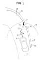
- FIGURE 1is a schematic diagram of an improved automatic lateral guidance control system in accordance with a preferred embodiment of the present invention.
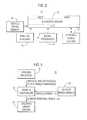
- FIGURE 2is an overall functional block diagram of the improved automatic lateral guidance control system of FIGURE 1.
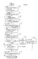
- FIGURE 3illustrates a sequence of steps which may be performed to operate the improved automatic lateral guidance control system of FIGURES 1 and 2.
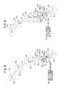
- FIGURE 4is a schematic diagram illustrating a set of steps in FIGURE 3 for calculating road geometry and determining heading angle.
- FIGURE 5is a block diagram of an improved automatic lateral guidance control system in accordance with a second embodiment of the present invention.
- FIGURE 6illustrates the improved automatic lateral guidance control system of FIGURE 5 operating with respect to a predetermined path.
- FIGURE 7illustrates a sequence of steps which may be performed to operate the improved automatic lateral guidance control system illustrated in FIGURES 5 and 6.
- FIGURE 8illustrates an improved automatic lateral guidance control system in accordance with a third embodiment of the present invention.
- FIGURE 9illustrates a sequence of steps which may be performed to operate the improved automatic lateral guidance control system of FIGURE 8.
- Figure 1is a schematic diagram of an improved automatic lateral guidance control system in accordance with a preferred embodiment of the present invention.
- Vehicle 8is equipped with automatic lateral guidance control system 10 which automatically guides the heading or forward direction of vehicle 8 with respect to actual path 28.
- a plurality of reflectors 34may be disposed adjacent to or along path 28.
- retroflectorswhich are well known in the art may be utilized for reflectors 34 in a preferred embodiment, the present invention is not intended to be limited thereto, and any suitable optical reflecting medium may be substituted for reflectors 34.
- a series of painted, reflective stripesmay be disposed along (i.e., following the length of) path 28.
- Actual path 28may comprise for example, a roadway, a lane of a highway or any other like predetermined route.
- Vehicle 8may comprise for example, an automobile, truck, bus, or any other suitable type of mobile vehicle for travelling along a predetermined route such as path 28.
- Automatic lateral guidance control system 10guides vehicle 8 in a generally forward direction along the forward, centerline axis of vehicle 8, which axis is hereinafter defined as vehicle heading 20.
- Automatic lateral guidance control system 10adjusts the course of vehicle 8 in order to cause the vehicle to follow path 28.
- automatic lateral guidance control system 10adjusts the course of vehicle 8 by determining the angular displacement between vehicle heading 20 and a straight line drawn from the front of vehicle 8 to selected target point 24, whereby target point 24 is a point located on ideal road geometry 29.
- ideal road geometry 29is a calculated approximation of actual path 28.
- Vehicle 8is then steered with respect to selected target point 24.
- the process of determining the vehicle's heading with respect to a selected target point on ideal road geometry 29, and correcting the vehicle's headingis an iterative process which is performed by a sequence of steps programmed into a microcomputer. Consequently, the process of determining and correcting the vehicle's heading is continuously repeated as the vehicle travels along the roadway.
- the system illustrated in Figures 1, 2 and 3is considered to comprise a continuum of target points 24 or "markers" disposed along ideal road geometry 29.
- a continuum of target points 24 or "markers”disposed along ideal road geometry 29.
- Such a systemis hereinafter referred to as a “continuous marker system.”
- ideal road geometry 29is hereinafter defined to be an accurate approximation of the curvature of actual path 28. In essence, road geometry 29 is substantially equivalent to actual path 28.
- a preferred technique for calculating ideal road geometry 29is discussed in substantive detail below.
- FIG. 2is an overall functional block diagram of the improved automatic lateral guidance control system of Figure 1.
- Automatic lateral guidance control system 10comprises vehicle speed sensor 32, preview sensors 16, signal processor 14, microcontroller 12, and steering servo system 18.
- Microcontroller 12comprises a microprocessor, read only memory (ROM), read access memory (RAM), and input/output ports (I/O ports). It should be understood that microcontroller 12 may also comprise any additional circuitry, such as A/D and D/A converters, combinational logic circuitry, latching circuitry, etc., that may be necessary for the operation and interconnection of microcontroller 12 with respect to the components of automatic lateral guidance control system 10. All of the above-described components of microcontroller 12 may be located on an individual semiconductor chip.
- microcontroller 12may comprise, for example, a Motorola MC68HC705C8 type microcontroller. Although the structure and operation of a specific type of microcontroller is described herein for illustrative purposes with respect to a preferred embodiment, the type of microcontroller selected is not critical to making and using the present invention, and the present invention is not intended to be limited thereto. Any suitable microcontroller or similarly constructed apparatus for performing the operations of the present invention may be substituted herein.
- vehicle speed sensor 32is coupled to microcontroller 12 and provides a measurement of the speed of vehicle 8.
- Vehicle speed sensor 32may comprise any of a number of conventional speed sensors for use in a motor vehicle such as, for example, a speed sensor connected to a wheel of vehicle 8.
- Preview sensors 16are coupled to an input of microcontroller 12 and provide measurements of the relative position, including distance and angle, of vehicle 8 with respect to at least one of reflectors 34 located along path 28.
- Preview sensors 16are also coupled to an input of signal processor 14 to provide the above-described distance and angle measurements to signal processor 14.
- An output from signal processor 14is coupled to an input of microcontroller 12.
- signal processor 14operates to receive position measurements of reflectors 34 relative to the heading of vehicle 8 from preview sensors 16, in order for signal processor 14 to calculate ideal road geometry 29 and provide ideal road geometry information to microcontroller 12.
- microcontroller 12may calculate road geometry 29 directly from the angle and distance measurements provided by preview sensors 16.
- Steering servo system 18is coupled to microcontroller 12 and may, for example, comprise a conventional steering control system including a steering controller and steering actuator. Steering servo system 18 operates to change the direction of vehicle 8 in response to control signals generated by microcontroller 12, in order to maintain the heading of vehicle 8 with respect to path 28.
- Preview sensors 16, which are electrically coupled to microcontroller 12 and signal processor 14,may be mounted on a right front portion of vehicle 8, for example, for use in a country (such as the United States) where vehicles typically travel on the right hand side of the road. Thus, preview sensors 16 may scan reflectors or other types of road markers disposed at or near the right hand side of the roadway. It is also envisioned that preview sensors 16 may be mounted in the center front portion of vehicle 8, in order to scan both sides of the roadway. Preview sensors 16 may comprise, for example, a laser transmitter/receiver (radar) system or other optical sensing apparatus, such as a video camera.
- radarlaser transmitter/receiver
- preview sensors 16are described herein with respect to an optical sensing apparatus for illustrative purposes only, but the present invention is not intended to be limited thereto.
- Preview sensors 16also may include other suitable sensing devices for determining angle and distance to each of a series of "markers" disposed adjacent to a roadway such as, for example, a receiver operating at radio-frequencies (RF) that detects and processes radiated signals from a series of RF "beacon” transmitters disposed adjacent to the road, or any other suitable sensing apparatus for sensing the distance and angle with respect to vehicle 8 and each of a series of energy reflecting or energy radiating "markers.”
- RFradio-frequencies
- the term “reflector”refers to any reflective medium for reflecting light energy.
- the term “marker”more broadly may refer either to an energy reflecting device or energy radiating device disposed adjacent to a roadway.
- the term “marker”may also refer to a section of material radiating a static magnetic field.
- each transmitter of preview sensors 16scans or radiates a beam of light to at least one of reflectors 34.
- the associated laser receiver of preview sensors 16receives a reflected signal from each of scanned reflectors 34.
- Preview sensors 16measure the distance and angle between each of scanned reflectors 34 and the heading of vehicle 8. This measurement information is provided to microcontroller 12 in order to determine the location of each of scanned reflectors 34 with respect to vehicle 8. This measurement information may be computed by preview sensors 16 by measuring a phase difference between the transmitted and received laser beams, or by using a pulsed laser beam and measuring propagation time to the reflector and back.
- the specific structure and operation of preview sensors 16is disclosed in detail in a commonly-assigned, copending application.
- Figure 3illustrates a sequence of steps which may be performed to operate the improved automatic lateral guidance control system of Figures 1 and 2.
- this sequence of stepsmay be performed by programming microcontroller 12 using well-known programming techniques.
- Such programming techniqueswould be known to a computer programmer of ordinary skill.
- preview sensors 16measure the distance and angle between each of said reflectors 34 (markers) and the heading of vehicle 8. This measurement information is provided both to microcontroller 12 and signal processor 14, in order for either microcontroller 12 or signal processor 14 to determine the relative location of each of said reflectors 34 with respect to vehicle 8.
- preview sensors 16scan an area that includes at least three of reflectors 34.
- the measurement information determining the relative position for each of the three scanned reflectors 34 with respect to vehicle 8is read into the memory area of microcontroller 12.
- the vehicle speed informationis also read into microcontroller 12 from vehicle speed sensor 32.
- microcontroller 12calculates ideal road geometry 29 from the angle and distance measurement information obtained from preview sensor 16.
- Figure 4is a schematic diagram illustrating a set of steps to be performed with respect to block 304 in Figure 3 for calculating ideal road geometry 29.
- preview sensors 16detects the angles and distances to at least three of reflectors 34. As illustrated by example in Figure 4, preview sensors 16 provide measurements of angles ⁇ 1, ⁇ 2 and ⁇ 3, and distances d1, d2 and d3 with respect to the scanned three of reflectors 34.
- ideal road geometry 29may also be determined by signal processor 14.
- Signal processor 14may also approximate the curvature of a portion of path 28 which has been scanned by preview sensors 16. Utilizing the angle and distance measurements with respect to three scanned markers or reflectors 34, signal processor 14 provides x, y coordinate information with respect to the position and heading of vehicle 8 and path 28, which represents an accurate approximation of the curvature of path 28 (i.e., ideal road geometry).
- An advantage of the approximation technique used in signal processor 14 over conventional techniquesis that the calculations for determining the ideal road geometry are performed with the assistance of so-called "neural network" computer technology.
- a set of functions approximating the curvature of path 28is constructed on a neural network computer, which is typically a general purpose computer. These functions are "learned" by the computer by experimentally constructing functions that satisfy known input and output data.
- Signal processor 14is programmed with the learned functions developed by the neural network computer. Signal processor 14 then provides coordinate values to microcontroller 12 that allow microcontroller 12 to determine the position and heading of vehicle 8 with respect to the approximated curvature of path 28 (i.e., ideal road geometry) that has been derived by signal processor 14.
- microcontroller 12may calculate ideal road geometry independently of any information to be provided from signal processor 14, and the use of signal processor 14 is presently considered only as an alternative or possible option for calculating ideal road geometry 29 which is not critical to making or using the present invention.
- microcontroller 12next determines preview distance 23.
- the determination of preview distanceis necessary in order to increase the reaction time available for guidance control system 10 to correct heading angle 22 in response to variations in the curvature of path 28.
- Preview distance 23is a distance projected from the front of vehicle 8, and is defined as the radius of half-circle 26.
- the length of preview distance 23is a function of the speed of vehicle 8.
- the actual values for preview distance 23are determined by experimentation, because the selection of optimum values for preview distance 23 is a trade-off between ride comfort in the vehicle and control system performance. Consequently, the values determined for preview distance 23 must be compatible with both ride comfort and system performance. However, these values may be readily determined by system designers of ordinary skill.
- preview distance 23must be sufficient to allow automatic lateral guidance control system 10 sufficient reaction time to determine heading angle 22 and to calculate the desired steering angle to be provided to steering servo system 18.
- microcontroller 12determines target point 24 based on the length of preview distance 23.
- Target point 24is determined as the intersection of the radius of half-circle 26 (i.e., the length of preview distance 23) with road geometry 29.
- Automatic lateral guidance control system 10as depicted in Figures 1, and 3, is defined as a continuous marker system because target point 24 may occur at any location along calculated road geometry 29. Thus, the target point may intersect a point on the approximated path even though no reflector or marker is actually located at that point.
- Target point 24is the intersection point (x t , y t ) defined by the solutions to equations (3) and (4) above.
- microcontroller 12calculates heading angle 22.
- Heading angle 22is the angle between vehicle heading 20 and a straight line from vehicle 8 to target point 24.
- Heading angle 22may be calculated according to any well known mathematical technique used for calculating angles.
- heading angle 22may be calculated with respect to Figure 4, by the following equation: where ⁇ is heading angle 22.
- FIG. 5is a block diagram of an improved automatic lateral guidance control system in accordance with a second embodiment of the present invention.
- automatic lateral guidance control system 70comprises microcontroller 12, preview sensors 16, vehicle speed sensor 32, and steering servo system 18.
- Signal processor 14which is utilized in the embodiment illustrated by Figures 1, 2 and 3, is not utilized in the present embodiment.
- This embodimentprovides an alternative structure to automatically guide a vehicle along a predetermined path.
- automatic lateral guidance control system 70provides a desired steering angle ⁇ d for controlling the heading of vehicle 8, by calculating a heading angle with respect to the position of a discrete reflector.
- the present embodimentis hereinafter called a "discrete marker system" of control, as opposed to the "continuous marker system” disclosed in the first embodiment.
- Figure 6illustrates the improved automatic lateral guidance control system of Figure 5 with vehicle 8 travelling along actual path 28.
- reflectors 34a-eare markers that are disposed at predetermined locations along path 28.
- the distance between each of reflectors 34a-eis a variable highway design constraint.
- the distance between each of reflectors 34a-eis approximately 50 feet in the State of California.
- automatic guidance control system 70guides vehicle 8 in a generally forward direction along the forward, centerline axis of vehicle 8, which has been previously defined as vehicle heading 20.
- heading angle 42is determined with respect to reflector 34b
- heading angle 43is determined with respect to reflector 34c.
- Minimum preview review distance 45is defined as the radius of circle 50.
- Minimum preview review distance 45is a distance projected from one of reflectors 34 and is defined as the radius of circle 50.
- the length of minimum preview review distance 45is a function of the speed of vehicle 8.
- the actual values for minimum preview review distance 45are determined by experimentation, because the selection of optimum values for minimum preview review distance 45 is a trade-off between ride comfort in the vehic!e and control system performance. Consequently, the values determined for minimum preview review distance 45 must be compatible with both ride comfort and system performance. However, these values may be readily determined by system designers of ordinary skill.
- minimum preview review distance 45must be sufficient to allow automatic guidance control system 70 sufficient reaction time to calculate heading angles 42 and 43, and the desired steering angle ⁇ d to be provided to steering servo system 18.
- Figure 7illustrates a sequence of steps which may be performed by microcontroller 12 to operate the improved automatic lateral guidance control system illustrated in Figures 5 and 6.
- blocks 602-628disclose a sequence of steps to be performed by microcontroller 12 in order to calculate a desired steering angle from angle and distance measurements to a discrete marker (reflector 34).
- the angle and distance measurements from reflectors 34are read in to microcontroller 12 from preview sensors 16.
- Preview sensors 16measure the distance and angle between each of reflectors 34 and vehicle 8.
- the vehicle speed information from vehicle speed sensor 32is also read in to microcontroller 12.
- microcontroller 12determines the length of preview distance 23 as a function of vehicle speed.
- microcontroller 12selects an initial target marker (reflector 34b in this instance) by selecting a marker having the smallest distance value which is still greater than or equal to the length of preview distance 23.
- microcontroller 12then calculates heading angle 42.
- Heading angle 42is the angle between vehicle heading 20 and a straight line from vehicle 8 to target marker 34b. Heading angle 42 may be calculated using the well-known mathematical techniques as disclosed above with respect to block 310 in Figure 3.
- microcontroller 12calculates desired steering angle ⁇ d to be provided to steering servo system 18, based on heading angle 42.
- microcontroller 12must provide a desired steering angle as an output to steering servo system 18 that causes vehicle 8 to steer in the direction of target marker 34b.
- the desired steering angleis equal to the control gain K times heading angle 42.
- the control gain Kis a function of vehicle speed and road curvature and is derived as described above with respect to the first embodiment.
- microcontroller 12determines the next reflector by knowledge of the distance and angle measurements. Then, in block 622, microcontroller 12 determines the magnitude of heading angle 43 (the heading angle with respect to selected target marker 34c). The magnitude of heading angle 43 is then provided for the calculation of desired steering angle in block 626. As shown in Figure 7, the process of selecting the next target marker and calculating a desired steering angle is then repeated by returning to block 614.
- Figure 8illustrates an improved automatic lateral guidance control system in accordance with a third embodiment of the present invention.
- the automatic lateral guidance control system disclosed with respect to the third embodimentcomprises the structure of system 70 as shown in Figure 5.
- Figure 8illustrates the improved automatic lateral guidance control system of Figure 5 with vehicle 8 travelling along actual path 28.
- Reflectors 34a-eare disposed at predetermined locations adjacent to path 28. The distance between each of reflectors 34a-e is a variable highway design constraint.
- automatic guidance control system 70guides vehicle 8 in a generally forward direction along the forward, centerline axis of vehicle 8, which has been previously defined as vehicle heading 20.
- Minimum preview review distance 45is defined as the radius of circle 50. Minimum preview review distance 45 is a distance projected from one of reflectors 34. The length of minimum preview review distance 45 is a function of the speed of vehicle 8 and is determined experimentally as described with respect to the above-discussed embodiments. The length of minimum preview review distance 45 must be sufficient to allow automatic guidance control system 70 sufficient reaction time to determine heading angles 42, 43 and 44 as they are being provided by preview sensor 16, and then to determine the desired steering angle to be provided to steering servo system 18.
- Figure 9illustrates a sequence of steps which may be performed by microcontroller 12 to operate improved automatic lateral guidance control system 70 of Figures 5 and 8.
- microcontroller 12is attempting to determine heading angles with respect to two target markers or reflectors at a time.
- automatic lateral guidance control system 70may still select at least one target marker and calculate a desired steering angle with respect to that marker even if one of the two reflectors or markers is missing from path 28, and angle and distance measurements to only one reflector is available at that point in time. Consequently, the system disclosed in the third embodiment is hereinafter referred to as a "fail-safe discrete marker system.”
- microcontroller 12compares distance 44 to minimum preview distance 45. If distance 44 (the distance from vehicle 8 to the current target marker or reflector 34b) is greater than or equal to minimum preview review distance 45, then the heading angle is defined as the sum of the weighted values of heading angles 42 and 43 as disclosed in block 828.
- the actual values for weights W1 and W2are determined by experimentation, so that the resultant heading angle (the sum of heading angles 42 and 43 in this instance) is a weighted average of heading angles 42 and 43.
- the resultant heading anglehas an angular value which is between the angular values of heading angles 42 and 43.
- This resultant heading angleis selected for optimum control system performance, and the values of W1 and W2 to provide the optimum heading angle may be readily determined by designers of ordinary skill.
- microcontroller 12determines the magnitude of the heading angle defined as the sum of the weighted values of heading angles 42 and 43.
- microcontroller 12then calculates the desired steering angle to be provided to steering servo system 18, wherein the desired steering angle ⁇ d is equal to the control gain K times the value of the heading angle determined in block 828.
- the heading angleis defined as the sum of the weighted values of heading angles 43 and 47.
- microcontroller 12determines the magnitude of the sum of the weighted values of heading angles 43 and 47.
- the heading angle determined by block 822is then provided for the step of calculating the desired steering angle in block 826, wherein the desired steering angle ⁇ d is equal to the control gain K times the value of the heading angle determined in block 822. As shown in Figure 9, the process is then repeated by returning to block 814.
Landscapes
- Engineering & Computer Science (AREA)
- Physics & Mathematics (AREA)
- Radar, Positioning & Navigation (AREA)
- Remote Sensing (AREA)
- Aviation & Aerospace Engineering (AREA)
- General Physics & Mathematics (AREA)
- Automation & Control Theory (AREA)
- Electromagnetism (AREA)
- Optics & Photonics (AREA)
- Control Of Position, Course, Altitude, Or Attitude Of Moving Bodies (AREA)
- Navigation (AREA)
Description

Claims (11)
- An apparatus for automatically guiding a moving vehicle(8) with respect to a road having a plurality of discrete markers(34) disposed along an actual path (28) predetermined byand adjacent to the course of the road, said apparatus comprising:speed sensing means (32) for sensing the speed of the movingvehicle (8) along the road and generating speed signals indicativeof the vehicle speed,position sensing means (16) for sensing the distance (dl,d2 ...) between the vehicle and each of said discrete markers(34) as well as the angle (α1, α2 ...) between the forward directionof the vehicle and the connection line between the vehicleand each of said discrete markers (34) and for generatingsaid marker position signals indicating the respective positionsthereof on the basis of said distance (d1, d2 ...) andsaid angle (α1, α2 ...),calculating means (12) responsive to said marker positionsignals for calculating an ideal road geometry on the basis ofsaid marker position signals as an approximation of said actualpath (28),calculating means (12) responsive to said speed signalsfor calculating a preview distance, which is projected from thefront of the vehicle, as a function of the vehicle speed,identifying means (12) for identifying a point (24) locatedon said approximated ideal road geometry (29) and spacedapart from said vehicle (8) by said preview distance,calculating means (12) for calculating a heading angle(22) between the vehicle forward direction and the direction tosaid point (24) located on the approximated ideal road geometry(29),calculating means (12) for calculating a control signalindicating a desired vehicle running direction on the basis ofsaid calculated heading angle (22), andsteering means (18) for steering said vehicle (8) in responseto said control signal.
- An apparatus for automatically guiding a moving vehicle(8) with respect to a road having a plurality of discrete markers(34) disposed along an actual path (28) predetermined byand adjacent to the course of the road, said apparatus comprising:speed sensing means (32) for sensing the speed of the movingvehicle (8) along the road and generating speed signals indicativeof the vehicle speed,position sensing means (16) for sensing said discretemarkers (34) and generating marker position signals indicatingthe respective positions thereof,selecting means (12) for selecting a first marker fromsaid plurality of discrete markers positioned along said actualpath (28),calculating means (12) responsive to said speed signalsfor calculating a minimum preview review distance, which isprojected from said selected first marker, as a function of thevehicle speed,comparing means (12) for comparing the distance betweenthe vehicle position and the position of said selected firstmarker with said minimum preview review distance projected fromsaid selected first marker and for selecting a second markernext to said first marker if the distance between said vehicleand the position of said selected first marker is smaller thansaid minimum preview review distance,means (12) for calculating an angle between the vehicleforward direction and a line which connects the vehicle withthe selected first marker or the selected second marker and forgenerating control signals indicating the angle, andsteering means (18) for steering said vehicle (8) in responseto said control signals towards the selected one of saidfirst and second markers.
- An apparatus for automatically guiding a moving vehicle(8) with respect to a road having a plurality of discrete markers(34) disposed along an actual path (28) predetermined byand adjacent to the course of the road, said apparatus comprising:speed sensing means (32) for sensing the speed of the movingvehicle (8) along the road and generating speed signals indicativeof the vehicle speed,selecting means (12) for selecting a first set of at leasttwo adjacent discrete markers from said plurality of discretemarkers positioned along said actual path (28),position sensing means (16) for sensing said first set ofmarkers (34) and generating marker position signals indicatingthe respective positions thereof,calculating means (12) responsive to said speed signalsfor calculating a minimum preview review distance, which isprojected from one of said first set of markers, as a functionof the vehicle speed,comparing means (12) for comparing the distance betweenthe vehicle position and the position of the nearest marker ofsaid first set of markers with said minimum preview review distanceand for selecting a second set of at least two adjacentdiscrete markers next to said first set of markers if the distancebetween said vehicle and the position of said nearestmarker is smaller than said minimum preview review distance,means (12) for calculating a middle angle between an anglewhich is made by the vehicle forward direction and a line connectingthe vehicle with one of adjacent two markers and an anglewhich is made by the vehicle forward direction and a lineconnecting the vehicle with the other of the adjacent two markersand for generating control signals indicating the middleangle, andsteering means (18) for steering said vehicle (8) in responseto said control signals towards a point along said path(28) which is located between said selected adjacent markers.
- An apparatus according to one of claims 1 to 3, whereinsaid position sensing means (16) comprises an optical sensingapparatus.
- An apparatus according to one of claims 1 to 3, whereinsaid calculating means (12) comprises a programmable microcontroller.
- An apparatus according to claim 1, wherein said identifyingmeans (12) comprises a programmable microcontroller.
- An apparatus according to one of claims 2 or 3, whereinsaid comparing means (12) comprises a programmable microcontroller.
- An apparatus according to claim 4, wherein said opticalsensing apparatus comprises a laser radar apparatus.
- An method for automatically guiding a moving vehicle(8) with respect to a road having a plurality of discrete markers(34) disposed along an actual path (28) predetermined byand adjacent to the course of the road, said method comprisingthe steps of:sensing the speed of the moving vehicle (8) along the roadand generating speed signals indicative of the vehicle speed,sensing said discrete markers (34) and generating markerposition signals indicating the respective positions thereof,calculating an ideal road geometry on the basis of saidmarker position signals as an approximation of said actual path(28),calculating a preview distance, which is projected fromthe front of the vehicle, as a function of the vehicle speed,identifying a point (24) located on said approximatedideal road geometry (29) and spaced apart from said vehicle (8) by said preview distance,calculating a heading angle (22) between the vehicle forwarddirection and the direction to said point (24) located onthe approximated ideal road geometry (29),calculating a control signal indicating a desired vehiclerunning direction on the basis of said calculated heading angle(22), andsteering said vehicle (8) in response to said control signal.
- A method for automatically guiding a moving vehicle(8) with respect to a road having a plurality of discrete markers(34) disposed along an actual path (28) predetermined byand adjacent to the course of the road, said method comprisingthe steps of:sensing the speed of the moving vehicle (8) along the roadand generating speed signals indicative of the vehicle speed,sensing said discrete markers (34) and generating markerposition signals indicating the respective positions thereof,selecting a first marker from said plurality of discretemarkers positioned along said actual path (28),calculating a minimum preview review distance, which isprojected from said selected first marker as a function of thevehicle speed,comparing the distance between the vehicle position andthe position of said selected first marker with said minimumpreview review distance projected from said selected firstmarker and for selecting a second marker next to said firstmarker if the distance between said vehicle and the position ofsaid selected first marker is smaller than said minimum previewreview distance,calculating an angle between the vehicle forward directionand a line which connects the vehicle with the selected firstmarker or the selected second marker and for generating controlsignals indicating the angle, andsteering said vehicle (8) in response to said control signalstowards the selected one of said first and second markers.
- A method for automatically guiding a moving vehicle(8) with respect to a road having a plurality of discrete markers(34) disposed along an actual path (28) predetermined byand adjacent to the course of the road, said method comprisingthe steps of:sensing the speed of the moving vehicle (8) along the roadand generating speed signals indicative of the vehicle speed,selecting a first set of at least two adjacent discretemarkers from said plurality of discrete markers positionedalong said actual path (28),sensing said first set of markers (34) and generatingmarker position signals indicating the respective positionsthereof,calculating a minimum preview review distance, which isprojected from one of said first set of markers, as a functionof the vehicle speed,comparing the distance between the vehicle position andthe position of the nearest marker of said first set of markerswith said minimum preview review distance and for selecting asecond set of at least two adjacent discrete markers next tosaid first set of markers if the distance between said vehicleand the position of said nearest marker is smaller than saidminimum preview review distance,calculating a middle angle between an angle which is madeby the vehicle forward direction and a line connecting the vehiclewith one of adjacent two markers and an angle which ismade by the vehicle forward direction and a line connecting thevehicle with the other of the adjacent two markers and for generatingcontrol signals indicating the middle angle, andsteering said vehicle (8) in response to said control signalstowards a point along said path (28) which is located betweensaid selected adjacent markers.
Applications Claiming Priority (2)
| Application Number | Priority Date | Filing Date | Title |
|---|---|---|---|
| US59229590A | 1990-10-03 | 1990-10-03 | |
| US592295 | 1990-10-03 |
Publications (3)
| Publication Number | Publication Date |
|---|---|
| EP0479271A2 EP0479271A2 (en) | 1992-04-08 |
| EP0479271A3 EP0479271A3 (en) | 1992-07-22 |
| EP0479271B1true EP0479271B1 (en) | 1998-09-09 |
Family
ID=24370117
Family Applications (1)
| Application Number | Title | Priority Date | Filing Date |
|---|---|---|---|
| EP91116832AExpired - LifetimeEP0479271B1 (en) | 1990-10-03 | 1991-10-02 | Automatic lateral guidance control system |
Country Status (4)
| Country | Link |
|---|---|
| US (1) | US5357432A (en) |
| EP (1) | EP0479271B1 (en) |
| JP (1) | JP3191958B2 (en) |
| DE (1) | DE69130147T2 (en) |
Cited By (6)
| Publication number | Priority date | Publication date | Assignee | Title |
|---|---|---|---|---|
| US8818042B2 (en) | 2004-04-15 | 2014-08-26 | Magna Electronics Inc. | Driver assistance system for vehicle |
| US8842176B2 (en) | 1996-05-22 | 2014-09-23 | Donnelly Corporation | Automatic vehicle exterior light control |
| US8917169B2 (en) | 1993-02-26 | 2014-12-23 | Magna Electronics Inc. | Vehicular vision system |
| US8993951B2 (en) | 1996-03-25 | 2015-03-31 | Magna Electronics Inc. | Driver assistance system for a vehicle |
| US9171217B2 (en) | 2002-05-03 | 2015-10-27 | Magna Electronics Inc. | Vision system for vehicle |
| US9436880B2 (en) | 1999-08-12 | 2016-09-06 | Magna Electronics Inc. | Vehicle vision system |
Families Citing this family (45)
| Publication number | Priority date | Publication date | Assignee | Title |
|---|---|---|---|---|
| EP0514343B1 (en)* | 1991-05-16 | 1998-03-04 | Aisin Seiki Kabushiki Kaisha | Automatic lateral guidance control system |
| JP3183966B2 (en)* | 1992-04-20 | 2001-07-09 | マツダ株式会社 | Vehicle travel control device |
| JP3394287B2 (en)* | 1993-06-18 | 2003-04-07 | 政典 杉坂 | Independent traveling vehicle |
| DE4332836C1 (en)* | 1993-09-27 | 1994-09-15 | Daimler Benz Ag | Device for steering a vehicle with controlled tracking |
| US5563787A (en)* | 1993-12-22 | 1996-10-08 | Kabushiki Kaisha Komatsu Seisakusho | Apparatus for measuring position of moving body and apparatus for measuring relative distance |
| DE4440859C2 (en)* | 1994-11-15 | 1998-08-06 | Alexander Kaske | Method and device for controlling an autonomously exploring robot |
| JP3191621B2 (en)* | 1995-03-14 | 2001-07-23 | トヨタ自動車株式会社 | Vehicle travel guidance system |
| JPH08314540A (en)* | 1995-03-14 | 1996-11-29 | Toyota Motor Corp | Vehicle guidance system |
| US5875408A (en)* | 1995-07-17 | 1999-02-23 | Imra America, Inc. | Automated vehicle guidance system and method for automatically guiding a vehicle |
| JP3289565B2 (en)* | 1995-08-23 | 2002-06-10 | トヨタ自動車株式会社 | Automatic steering system |
| US5708427A (en)* | 1996-04-18 | 1998-01-13 | Bush; E. William | Vehicle in-lane positional indication/control by phase detection of RF signals induced in completely-passive resonant-loop circuits buried along a road lane |
| JP3588922B2 (en)* | 1996-07-08 | 2004-11-17 | トヨタ自動車株式会社 | Vehicle travel guidance system |
| JPH1031799A (en)* | 1996-07-15 | 1998-02-03 | Toyota Motor Corp | Automatic driving control device |
| DE19632929C1 (en)* | 1996-08-16 | 1997-11-27 | Daimler Benz Ag | Automatic motor vehicle transverse guidance device |
| US6760061B1 (en) | 1997-04-14 | 2004-07-06 | Nestor Traffic Systems, Inc. | Traffic sensor |
| US6219596B1 (en)* | 1997-09-18 | 2001-04-17 | Mitsubishi Denki Kabushiki Kaisha | Automated highway tracking and communication system and method |
| JP2000172336A (en)* | 1998-09-29 | 2000-06-23 | Toyota Motor Corp | Guideway traffic system and self-driving vehicle used in the system |
| US6754663B1 (en) | 1998-11-23 | 2004-06-22 | Nestor, Inc. | Video-file based citation generation system for traffic light violations |
| AU761072C (en) | 1998-11-23 | 2003-07-10 | Nestor, Inc. | Traffic light violation prediction and recording system |
| US6078849A (en)* | 1998-12-11 | 2000-06-20 | Lockheed Martin Corporation | Vision based precision docking of vehicles |
| DE10000785A1 (en)* | 2000-01-11 | 2001-07-12 | Bosch Gmbh Robert | Selecting method for microprocessor of microcontroller during boundary scan testing involves controlling JTAG interface of microprocessor from test routine executable on microprocessor |
| JP3715858B2 (en)* | 2000-01-18 | 2005-11-16 | 三菱電機株式会社 | Electric power steering device |
| US6285930B1 (en) | 2000-02-28 | 2001-09-04 | Case Corporation | Tracking improvement for a vision guidance system |
| US6490539B1 (en) | 2000-02-28 | 2002-12-03 | Case Corporation | Region of interest selection for varying distances between crop rows for a vision guidance system |
| US6278918B1 (en) | 2000-02-28 | 2001-08-21 | Case Corporation | Region of interest selection for a vision guidance system |
| US6686951B1 (en) | 2000-02-28 | 2004-02-03 | Case, Llc | Crop row segmentation by K-means clustering for a vision guidance system |
| US6385515B1 (en) | 2000-06-15 | 2002-05-07 | Case Corporation | Trajectory path planner for a vision guidance system |
| US6445983B1 (en) | 2000-07-07 | 2002-09-03 | Case Corporation | Sensor-fusion navigator for automated guidance of off-road vehicles |
| IL145680A0 (en) | 2001-09-26 | 2002-06-30 | Friendly Robotics Ltd | Robotic vacuum cleaner |
| EP1441632B1 (en)* | 2001-09-26 | 2013-05-01 | F. Robotics Acquisitions Ltd. | Robotic vacuum cleaner |
| US7002270B2 (en)* | 2003-01-02 | 2006-02-21 | Siemens Westinghouse Power Corporation | Generator rotor conductive path for connecting to a top-turn of a winding |
| JP3922194B2 (en) | 2003-03-11 | 2007-05-30 | 日産自動車株式会社 | Lane departure warning device |
| KR100552691B1 (en)* | 2003-09-16 | 2006-02-20 | 삼성전자주식회사 | Method and apparatus for estimating magnetic position and azimuth of mobile robot |
| US7239958B2 (en)* | 2003-12-18 | 2007-07-03 | General Motors Corporation | Apparatus and method for discerning a driver's intent and for aiding the driver |
| TW200526441A (en)* | 2004-02-06 | 2005-08-16 | Shih-Po Lan | A vehicle light beam guide |
| KR100624387B1 (en)* | 2005-04-25 | 2006-09-20 | 엘지전자 주식회사 | Robot system with driving range |
| WO2008024639A2 (en) | 2006-08-11 | 2008-02-28 | Donnelly Corporation | Automatic headlamp control system |
| GB2482120B (en)* | 2010-07-19 | 2013-01-30 | China Ind Ltd | Racing vehicle game |
| GB2482119B (en) | 2010-07-19 | 2013-01-23 | China Ind Ltd | Racing vehicle game |
| US9545048B2 (en)* | 2011-08-15 | 2017-01-17 | Deere & Company | System for automated unloading of an agricultural material |
| WO2017168945A1 (en)* | 2016-03-30 | 2017-10-05 | 三菱電機株式会社 | Travel direction estimation device |
| CN110398979B (en)* | 2019-06-25 | 2022-03-04 | 天津大学 | A tracking method and device for unmanned engineering operation equipment based on vision and attitude fusion |
| CN112937580B (en)* | 2019-11-25 | 2023-04-14 | 宇通客车股份有限公司 | Target path tracking method and device |
| CN112590930A (en)* | 2020-12-11 | 2021-04-02 | 国汽(北京)智能网联汽车研究院有限公司 | Steering angle determination method and device of autonomous operation equipment and computer equipment |
| CN113552888B (en)* | 2021-07-29 | 2022-07-19 | 中国第一汽车股份有限公司 | Driving track control method, device, equipment and medium applied to unmanned vehicle |
Family Cites Families (126)
| Publication number | Priority date | Publication date | Assignee | Title |
|---|---|---|---|---|
| US3172496A (en)* | 1962-01-15 | 1965-03-09 | Rabinow Jacob | Vehicle guidance by optical means |
| DE1219984B (en)* | 1964-05-19 | 1966-06-30 | Licentia Gmbh | Static counter for counting up and down pulses |
| US3466451A (en)* | 1966-05-31 | 1969-09-09 | Gen Electric | Photoelectric device for sensing indicia on a moving medium |
| DE1913398C3 (en)* | 1969-03-17 | 1974-12-12 | Siemens Ag, 1000 Berlin Und 8000 Muenchen | Arrangement for the controlled guidance of a work machine with the help of laser beams |
| DE2016815C3 (en)* | 1970-04-08 | 1973-10-11 | Siemens Ag, 1000 Berlin U. 8000 Muenchen | Holographic adjustment process and arrangements for this |
| US3708668A (en)* | 1971-06-01 | 1973-01-02 | J Tilley | Vehicle optical guidance system |
| JPS5512605B2 (en)* | 1971-11-30 | 1980-04-03 | ||
| US3802780A (en)* | 1972-06-12 | 1974-04-09 | Us Army | Optical device for position location |
| US4195425A (en)* | 1972-07-17 | 1980-04-01 | Ernst Leitz Wetzlar Gmbh | System for measuring position and/or velocity |
| US4185919A (en)* | 1973-06-08 | 1980-01-29 | The United States Of America As Represented By The Secretary Of The Air Force | Quadrant detection system |
| US4181435A (en)* | 1973-06-29 | 1980-01-01 | The United States Of America As Represented By The Secretary Of The Air Force | Holographic field lens detector |
| US4007991A (en)* | 1973-07-02 | 1977-02-15 | Saab-Scania Aktiebolag | System for transmitting position information |
| US3918172A (en)* | 1973-12-26 | 1975-11-11 | Hydro Quebec | Method and apparatus for determining geodesic measurements by helicopter |
| FR2271611B1 (en)* | 1974-02-01 | 1977-03-04 | Thomson Csf | |
| US3970840A (en)* | 1974-07-16 | 1976-07-20 | Lear Siegler, Inc. | Control circuitry for vehicle guidance mechanism |
| FR2295495A1 (en)* | 1974-12-20 | 1976-07-16 | Thomson Csf | REMOTE IDENTIFICATION DEVICE FOR OBJECTS CONTAINING ENCODED INFORMATION |
| JPS51101561A (en)* | 1975-03-05 | 1976-09-08 | Japan National Railway | Kogakushikikidokuruisokuteisochi |
| DE2518120A1 (en)* | 1975-04-24 | 1976-11-04 | Daimler Benz Ag | TRAFFIC SYSTEM, IN PARTICULAR PUBLIC PERSONAL TRAFFIC SYSTEM |
| US4184767A (en)* | 1975-07-21 | 1980-01-22 | The United States Of America As Represented By The Secretary Of The Navy | Frequency agile optical radar |
| DE2546714A1 (en)* | 1975-10-17 | 1977-04-21 | Siemens Ag | METHOD OF MEASURING THE DISTANCE FROM AND THE SPEED COMPONENT OF AN OBJECT VERTICAL TO A REFERENCE LINE |
| BR7608673A (en)* | 1975-12-26 | 1978-01-03 | Seiko Instr & Electronics | PROCESS FOR OPTICAL MEDICATION OF A DISTANCE |
| JPS5317034A (en)* | 1976-07-30 | 1978-02-16 | Sharp Corp | Image sensor output correcting system |
| US4099591A (en)* | 1976-09-02 | 1978-07-11 | Westinghouse Electric Corp. | Vehicle control scanning system |
| US4227812A (en)* | 1977-03-10 | 1980-10-14 | Centre De Recherches Metallurgiques Centrum Voor Research In De Metallurgie | Method of determining a dimension of an article |
| US4313654A (en)* | 1977-09-06 | 1982-02-02 | Minolta Camera Kabushiki Kaisha | Automatic rangefinder system for photographic camera with light emitting and receiving means |
| US4157533A (en)* | 1977-11-25 | 1979-06-05 | Recognition Equipment Incorporated | Independent channel automatic gain control for self-scanning photocell array |
| US4168908A (en)* | 1977-12-30 | 1979-09-25 | The United States Of America As Represented By The Secretary Of The Air Force | Precision pointing and tracking control system |
| US4160237A (en)* | 1978-02-02 | 1979-07-03 | Sperry Rand Corporation | Optical reader for multiline image processing |
| SE412959B (en)* | 1978-03-02 | 1980-03-24 | Saab Scania Ab | SET TO DETERMINE THE DOCTOR FOR A NUMBER OF FOREMAL AND SYSTEM FOR EXECUTING THE SET |
| SE418909B (en)* | 1978-03-02 | 1981-06-29 | Saab Scania Ab | KIT AND PLANT TO MODEL MODULATED OPTICAL RADIATION TRANSFER INFORMATION FOR FORMAL |
| US4187027A (en)* | 1978-04-20 | 1980-02-05 | Bell Telephone Laboratories, Incorporated | Servo-control alignment of nonlinear crystals |
| US4227807A (en)* | 1978-04-28 | 1980-10-14 | The Boeing Company | Holographic angle sensor |
| US4180322A (en)* | 1978-05-01 | 1979-12-25 | Alcyon Equipment S.A. | Interior measurement of enclosed spaces |
| US4278142A (en)* | 1978-05-08 | 1981-07-14 | Agency Of Industrial Science And Technology | Automatic guidance system for vehicles |
| EP0007790A1 (en)* | 1978-08-01 | 1980-02-06 | Imperial Chemical Industries Plc | Driverless vehicle carrying non-directional detectors auto-guided by light signals |
| JPS5527987A (en)* | 1978-08-21 | 1980-02-28 | Minolta Camera Co Ltd | Distance measuring instrument |
| US4225226A (en)* | 1978-12-29 | 1980-09-30 | Spectra-Physics, Inc. | Laser guidance system for crop spraying aircraft |
| JPS5596475A (en)* | 1979-01-19 | 1980-07-22 | Nissan Motor Co Ltd | Obstacle detector for vehicle |
| US4269512A (en)* | 1979-02-21 | 1981-05-26 | Nosler John C | Electro-optical position-monitoring apparatus with tracking detector |
| FR2453418A1 (en)* | 1979-04-06 | 1980-10-31 | Thomson Csf | OPTOELECTRIC DEVICE FOR LOCATING A PUNCTUAL LIGHT SOURCE AND SYSTEMS COMPRISING SUCH DEVICES |
| US4373804A (en)* | 1979-04-30 | 1983-02-15 | Diffracto Ltd. | Method and apparatus for electro-optically determining the dimension, location and attitude of objects |
| US4259009A (en)* | 1979-07-30 | 1981-03-31 | The United States Of America As Represented By The Secretary Of The Navy | Far field target designators |
| US4383230A (en)* | 1979-09-24 | 1983-05-10 | Manzolini David B | Voltage tuned active filter and circuitry simulating a capacitance and an inductance |
| JPS5675626A (en)* | 1979-11-26 | 1981-06-22 | Minolta Camera Co Ltd | Distance measuring device |
| DE3002791C2 (en)* | 1980-01-26 | 1983-04-28 | Deutsche Forschungs- und Versuchsanstalt für Luft- und Raumfahrt e.V., 5000 Köln | Procedure for measuring visibility, oblique visibility and cloud height |
| FR2476326A1 (en)* | 1980-02-20 | 1981-08-21 | Cilas | DEVICE FOR DETERMINING THE ANGULAR POSITION OF A TARGET LIGHTED BY LIGHT PULSES |
| US4333147A (en)* | 1980-05-13 | 1982-06-01 | General Motors Corporation | Multiplexed inductive automated guidance for moving vehicles |
| US4349277A (en)* | 1980-06-11 | 1982-09-14 | General Electric Company | Non-contact measurement of surface profile |
| JPS577508A (en)* | 1980-06-16 | 1982-01-14 | Seiko Koki Kk | Distance detector |
| US4486095A (en)* | 1980-06-27 | 1984-12-04 | Movement Techniques Limited | Movement measuring apparatus and landmarks for use therewith |
| US4441810A (en)* | 1980-07-15 | 1984-04-10 | Konishiroku Photo Industry Co., Ltd. | Range finder |
| JPS5748703A (en)* | 1980-09-08 | 1982-03-20 | Seiko Koki Kk | Distance detector |
| US4443103A (en)* | 1980-12-18 | 1984-04-17 | The Boeing Company | Retro-reflective electro-optical angle measuring system |
| JPS57128810A (en)* | 1981-02-03 | 1982-08-10 | Olympus Optical Co Ltd | Distance measuring device |
| US4401886A (en)* | 1981-03-23 | 1983-08-30 | The Boeing Company | Electromagnetic beam acquisition and tracking system |
| NL8101669A (en)* | 1981-04-03 | 1982-11-01 | Philips Nv | DEVICE FOR DETECTING THE POSITION OF AN OBJECT. |
| US4769700A (en)* | 1981-11-20 | 1988-09-06 | Diffracto Ltd. | Robot tractors |
| US4515472A (en)* | 1981-08-25 | 1985-05-07 | Ltv Aerospace And Defense Co. | Agile receiver for a scanning laser radar |
| US4515471A (en)* | 1981-08-25 | 1985-05-07 | Ltv Aerospace And Defense Company | Scanning laser radar |
| US4484069A (en)* | 1981-10-15 | 1984-11-20 | St. Regis Paper Company | Apparatus and method for sensing distance |
| US4456829A (en)* | 1981-10-29 | 1984-06-26 | K. J. Law Engineers, Inc. | Non-contact sensor, system and method with particular utility for measurement of road profile |
| JPS5876784A (en)* | 1981-10-31 | 1983-05-09 | Nissan Motor Co Ltd | Light pulse radar apparatus for vehicles |
| JPS58113807A (en)* | 1981-12-28 | 1983-07-06 | Canon Inc | Distance measuring device |
| US4498768A (en)* | 1982-02-16 | 1985-02-12 | The United States Of America As Represented By The Secretary Of The Army | Angle of arrival meter |
| IT1156245B (en)* | 1982-03-01 | 1987-01-28 | Selenia Ind Elettroniche | DEVICE FOR DETERMINING THE DISTANCE OF AN AREA ILLUMINATED BY A PULSE LASER |
| US4511248A (en)* | 1982-06-30 | 1985-04-16 | Eastman Kodak Company | Active electro-optical distance detection methods and devices |
| US4497065A (en)* | 1982-07-12 | 1985-01-29 | Westinghouse Electric Corp. | Target recognition system enhanced by active signature measurements |
| JPS5925442A (en)* | 1982-07-31 | 1984-02-09 | Nippon Soken Inc | Ultrasonic wave device for car |
| US4569078A (en)* | 1982-09-17 | 1986-02-04 | Environmental Research Institute Of Michigan | Image sensor |
| US4556313A (en)* | 1982-10-18 | 1985-12-03 | United States Of America As Represented By The Secretary Of The Army | Short range optical rangefinder |
| JPS59112312A (en)* | 1982-12-20 | 1984-06-28 | Nippon Yusoki Co Ltd | Guiding band of unmanned carrier car |
| JPS59203975A (en)* | 1983-05-06 | 1984-11-19 | Nissan Motor Co Ltd | Vehicle optical radar device |
| GB8313338D0 (en)* | 1983-05-14 | 1983-06-22 | Gen Electric Co Plc | Vehicle control |
| GB8313339D0 (en)* | 1983-05-14 | 1983-06-22 | Gen Electric Co Plc | Vehicle guidance |
| US4644146A (en)* | 1983-06-29 | 1987-02-17 | Calspan Corporation | Robotic vehicle optical guidance system |
| US4627734A (en)* | 1983-06-30 | 1986-12-09 | Canadian Patents And Development Limited | Three dimensional imaging method and device |
| US4700301A (en)* | 1983-11-02 | 1987-10-13 | Dyke Howard L | Method of automatically steering agricultural type vehicles |
| DE3342675A1 (en)* | 1983-11-25 | 1985-06-05 | Fa. Carl Zeiss, 7920 Heidenheim | METHOD AND DEVICE FOR CONTACTLESS MEASUREMENT OF OBJECTS |
| CA1185085A (en)* | 1983-12-30 | 1985-04-09 | Laurent J. Paquet | Alignment system |
| DE3584642D1 (en)* | 1984-04-17 | 1991-12-19 | Kawasaki Heavy Ind Ltd | DEVICE FOR GENERATING A THREE-DIMENSIONAL COPY OF AN OBJECT. |
| NL8401649A (en)* | 1984-05-23 | 1985-12-16 | Optische Ind De Oude Delft Nv | MEASURING SYSTEM FOR THE PRESSURE MEASUREMENT, USING A TRIANGULAR PRINCIPLE, OF THE DISTANCE BETWEEN A PARTICULAR POINT OF THE OBJECTIVE AND A REFERENCE LEVEL. |
| ZA853615B (en)* | 1984-05-31 | 1986-02-26 | Ici Plc | Vehicle guidance means |
| JPS60256076A (en)* | 1984-06-01 | 1985-12-17 | Nissan Motor Co Ltd | Apparatus for detecting preceding car |
| JPS616033A (en)* | 1984-06-15 | 1986-01-11 | Nippon Soken Inc | Speed control device for car |
| DE3423536C2 (en)* | 1984-06-26 | 1986-09-11 | Erwin Sick Gmbh Optik-Elektronik, 7808 Waldkirch | Photoelectric protection zone device on a vehicle |
| JPS6123985A (en)* | 1984-07-13 | 1986-02-01 | Nissan Motor Co Ltd | Inter-vehicle distance detection device |
| US4615615A (en)* | 1984-09-27 | 1986-10-07 | Flexible Manufacturing Systems, Inc. | Laser positioning system |
| USH341H (en)* | 1984-11-09 | 1987-10-06 | The United States Of America As Represented By The Secretary Of The Army | Dual mode scanner/tracker |
| JPS61144615A (en)* | 1984-12-18 | 1986-07-02 | Canon Inc | automatic focus detection device |
| US4721385A (en)* | 1985-02-11 | 1988-01-26 | Raytheon Company | FM-CW laser radar system |
| US4630109A (en)* | 1985-02-28 | 1986-12-16 | Standard Telephones & Cables Public Limited Company | Vehicle tracking system |
| JPS61204713A (en)* | 1985-03-07 | 1986-09-10 | Murata Mach Ltd | Guidance system for unmanned running car |
| US4729660A (en)* | 1985-03-22 | 1988-03-08 | Toshihiro Tsumura | Position measuring apparatus of moving vehicle |
| US4940925A (en) | 1985-08-30 | 1990-07-10 | Texas Instruments Incorporated | Closed-loop navigation system for mobile robots |
| SE451770B (en) | 1985-09-17 | 1987-10-26 | Hyypae Ilkka Kalevi | KIT FOR NAVIGATION OF A LARGE VESSEL IN ONE PLAN, EXTRA A TRUCK, AND TRUCK FOR EXTENDING THE KIT |
| US4796998A (en) | 1985-10-03 | 1989-01-10 | Pasco Corporation | Method for mobile survey of road surface |
| US4834531A (en) | 1985-10-31 | 1989-05-30 | Energy Optics, Incorporated | Dead reckoning optoelectronic intelligent docking system |
| DE3540157A1 (en)* | 1985-11-13 | 1987-05-21 | Messerschmitt Boelkow Blohm | METHOD AND DEVICE FOR DISTANCE MEASUREMENT |
| US4761561A (en)* | 1985-11-27 | 1988-08-02 | Nippon Kogaku K.K. | Laser beam scanning pattern generation system with positional and dimensional error correction |
| US4734572A (en)* | 1986-02-14 | 1988-03-29 | Unimation Inc. | Dual light source locating and tracking system |
| US4817000A (en) | 1986-03-10 | 1989-03-28 | Si Handling Systems, Inc. | Automatic guided vehicle system |
| US4815840A (en) | 1986-05-16 | 1989-03-28 | Benayad Cherif Faycal E K | Position locating system for a vehicle |
| SE455539B (en) | 1986-05-23 | 1988-07-18 | Electrolux Ab | ELECTROOPTIC POSITION KNOWLEDGE SYSTEM FOR A PLAN REALLY FORMULA, PREFERRED A MOBILE ROBOT |
| US4721386A (en)* | 1986-07-18 | 1988-01-26 | Barnes Engineering Company | Three-axis angular monitoring system |
| JPH0812044B2 (en) | 1986-09-10 | 1996-02-07 | 株式会社東海理化電機製作所 | Tape edge coordinate measuring method and device |
| US4878754A (en) | 1986-10-16 | 1989-11-07 | Tokyo Keiki Co. Ltd. | Method of and apparatus for measuring irregularities of road surface |
| US4796198A (en)* | 1986-10-17 | 1989-01-03 | The United States Of America As Represented By The United States Department Of Energy | Method for laser-based two-dimensional navigation system in a structured environment |
| DE3635396A1 (en) | 1986-10-17 | 1988-04-28 | Bayerische Motoren Werke Ag | DEVICE FOR DETECTING OBSTACLES FOR MOTOR VEHICLES |
| US4811229A (en) | 1987-01-05 | 1989-03-07 | Hewlett-Packard Company | Control system for automatic guided vehicles |
| US4788439A (en)* | 1987-02-05 | 1988-11-29 | Santa Barbara Research Center | Multiple detector fog suppression and edge enhancement |
| US4855915A (en) | 1987-03-13 | 1989-08-08 | Dallaire Rodney J | Autoguided vehicle using reflective materials |
| US4947094A (en) | 1987-07-23 | 1990-08-07 | Battelle Memorial Institute | Optical guidance system for industrial vehicles |
| US4858132A (en) | 1987-09-11 | 1989-08-15 | Ndc Technologies, Inc. | Optical navigation system for an automatic guided vehicle, and method |
| US4790402A (en)* | 1987-09-28 | 1988-12-13 | Tennant Company | Automated guided vehicle |
| US4846297A (en) | 1987-09-28 | 1989-07-11 | Tennant Company | Automated guided vehicle |
| US4818100A (en) | 1987-09-30 | 1989-04-04 | Eaton Corporation | Laser doppler and time of flight range measurement |
| CH674675A5 (en) | 1987-10-23 | 1990-06-29 | Kern & Co Ag | |
| US4877311A (en) | 1988-01-19 | 1989-10-31 | Kearfott Guidance & Navigation Corporation | Laser power monitoring optics for a ring laser gyroscope |
| US4902126A (en) | 1988-02-09 | 1990-02-20 | Fibertek, Inc. | Wire obstacle avoidance system for helicopters |
| US4876444A (en) | 1988-03-07 | 1989-10-24 | Tennant Company | Protection from extraneous light for light guided vehicle |
| JP2660727B2 (en)* | 1988-08-10 | 1997-10-08 | 本田技研工業株式会社 | Automatic traveling device |
| US4895440A (en) | 1988-08-22 | 1990-01-23 | Spectra-Physics, Inc. | Laser-based measurement system |
| US4918607A (en) | 1988-09-09 | 1990-04-17 | Caterpillar Industrial Inc. | Vehicle guidance system |
| US4903054A (en) | 1988-09-23 | 1990-02-20 | Caterpillar Industrial Inc. | Obstacle detection system |
| EP0361914B1 (en) | 1988-09-28 | 1995-12-13 | Honda Giken Kogyo Kabushiki Kaisha | A driving way judging device and method |
| US4970653A (en) | 1989-04-06 | 1990-11-13 | General Motors Corporation | Vision method of detecting lane boundaries and obstacles |
- 1991
- 1991-10-02DEDE69130147Tpatent/DE69130147T2/ennot_activeExpired - Fee Related
- 1991-10-02EPEP91116832Apatent/EP0479271B1/ennot_activeExpired - Lifetime
- 1991-10-03JPJP25668291Apatent/JP3191958B2/ennot_activeExpired - Fee Related
- 1993
- 1993-11-24USUS08/156,943patent/US5357432A/ennot_activeExpired - Lifetime
Cited By (10)
| Publication number | Priority date | Publication date | Assignee | Title |
|---|---|---|---|---|
| US8917169B2 (en) | 1993-02-26 | 2014-12-23 | Magna Electronics Inc. | Vehicular vision system |
| US8993951B2 (en) | 1996-03-25 | 2015-03-31 | Magna Electronics Inc. | Driver assistance system for a vehicle |
| US8842176B2 (en) | 1996-05-22 | 2014-09-23 | Donnelly Corporation | Automatic vehicle exterior light control |
| US9436880B2 (en) | 1999-08-12 | 2016-09-06 | Magna Electronics Inc. | Vehicle vision system |
| US9171217B2 (en) | 2002-05-03 | 2015-10-27 | Magna Electronics Inc. | Vision system for vehicle |
| US9555803B2 (en) | 2002-05-03 | 2017-01-31 | Magna Electronics Inc. | Driver assistance system for vehicle |
| US8818042B2 (en) | 2004-04-15 | 2014-08-26 | Magna Electronics Inc. | Driver assistance system for vehicle |
| US9008369B2 (en) | 2004-04-15 | 2015-04-14 | Magna Electronics Inc. | Vision system for vehicle |
| US9191634B2 (en) | 2004-04-15 | 2015-11-17 | Magna Electronics Inc. | Vision system for vehicle |
| US9428192B2 (en) | 2004-04-15 | 2016-08-30 | Magna Electronics Inc. | Vision system for vehicle |
Also Published As
| Publication number | Publication date |
|---|---|
| US5357432A (en) | 1994-10-18 |
| DE69130147D1 (en) | 1998-10-15 |
| DE69130147T2 (en) | 1999-04-01 |
| EP0479271A3 (en) | 1992-07-22 |
| JPH04270402A (en) | 1992-09-25 |
| JP3191958B2 (en) | 2001-07-23 |
| EP0479271A2 (en) | 1992-04-08 |
Similar Documents
| Publication | Publication Date | Title |
|---|---|---|
| EP0479271B1 (en) | Automatic lateral guidance control system | |
| US5390118A (en) | Automatic lateral guidance control system | |
| EP0514343B1 (en) | Automatic lateral guidance control system | |
| US4757450A (en) | Method and system for automatically detecting a preceding vehicle | |
| EP0936518B1 (en) | Integrated vehicle positioning and navigation system, apparatus and method | |
| US4727492A (en) | Vehicle control and guidance system | |
| CA2307206C (en) | Method and device for association of anonymous reflectors to detected angle positions | |
| US6025797A (en) | Angular shift determining apparatus for determining angular shift of central axis of radar used in automotive obstacle detection system | |
| Durrant-Whyte | An autonomous guided vehicle for cargo handling applications | |
| US6147637A (en) | Obstacle detecting system for automotive vehicle | |
| US4716298A (en) | System for automatically detecting presence or absence of a preceding vehicle and method therefor | |
| US4817000A (en) | Automatic guided vehicle system | |
| JPH036472B2 (en) | ||
| EP0773452A1 (en) | Radar apparatus for detecting a direction of a center of a target | |
| JPH09115093A (en) | Vehicle automatic guidance device and method | |
| US20190243378A1 (en) | Radar-based guidance and wireless control for automated vehicle platooning and lane keeping on an automated highway system | |
| Simon et al. | Vehicle guidance for an autonomous vehicle | |
| CN118113041A (en) | Obstacle avoidance method and system by combining ultrasonic waves and laser radar | |
| KR20220056299A (en) | Radar control system and method of vehicle | |
| US6036209A (en) | System for managing safe mobile run by scanning lane | |
| WO2022112175A1 (en) | Road marking detection | |
| JP3149661B2 (en) | Automatic guided vehicle position identification method | |
| Wang et al. | A 3D scanning laser rangefinder and its application to an autonomous guided vehicle | |
| Langer et al. | A reactive system for off-road navigation | |
| JPH06148329A (en) | Vehicular gap detection apparatus |
Legal Events
| Date | Code | Title | Description |
|---|---|---|---|
| PUAI | Public reference made under article 153(3) epc to a published international application that has entered the european phase | Free format text:ORIGINAL CODE: 0009012 | |
| AK | Designated contracting states | Kind code of ref document:A2 Designated state(s):DE FR GB | |
| PUAL | Search report despatched | Free format text:ORIGINAL CODE: 0009013 | |
| AK | Designated contracting states | Kind code of ref document:A3 Designated state(s):DE FR GB | |
| 17P | Request for examination filed | Effective date:19930113 | |
| 17Q | First examination report despatched | Effective date:19930706 | |
| GRAG | Despatch of communication of intention to grant | Free format text:ORIGINAL CODE: EPIDOS AGRA | |
| GRAG | Despatch of communication of intention to grant | Free format text:ORIGINAL CODE: EPIDOS AGRA | |
| GRAH | Despatch of communication of intention to grant a patent | Free format text:ORIGINAL CODE: EPIDOS IGRA | |
| GRAH | Despatch of communication of intention to grant a patent | Free format text:ORIGINAL CODE: EPIDOS IGRA | |
| GRAA | (expected) grant | Free format text:ORIGINAL CODE: 0009210 | |
| AK | Designated contracting states | Kind code of ref document:B1 Designated state(s):DE FR GB | |
| REF | Corresponds to: | Ref document number:69130147 Country of ref document:DE Date of ref document:19981015 | |
| ET | Fr: translation filed | ||
| PLBE | No opposition filed within time limit | Free format text:ORIGINAL CODE: 0009261 | |
| STAA | Information on the status of an ep patent application or granted ep patent | Free format text:STATUS: NO OPPOSITION FILED WITHIN TIME LIMIT | |
| 26N | No opposition filed | ||
| REG | Reference to a national code | Ref country code:GB Ref legal event code:IF02 | |
| PGFP | Annual fee paid to national office [announced via postgrant information from national office to epo] | Ref country code:GB Payment date:20050928 Year of fee payment:15 | |
| PGFP | Annual fee paid to national office [announced via postgrant information from national office to epo] | Ref country code:DE Payment date:20050929 Year of fee payment:15 | |
| PGFP | Annual fee paid to national office [announced via postgrant information from national office to epo] | Ref country code:FR Payment date:20051010 Year of fee payment:15 | |
| PG25 | Lapsed in a contracting state [announced via postgrant information from national office to epo] | Ref country code:DE Free format text:LAPSE BECAUSE OF NON-PAYMENT OF DUE FEES Effective date:20070501 | |
| GBPC | Gb: european patent ceased through non-payment of renewal fee | Effective date:20061002 | |
| REG | Reference to a national code | Ref country code:FR Ref legal event code:ST Effective date:20070629 | |
| PG25 | Lapsed in a contracting state [announced via postgrant information from national office to epo] | Ref country code:GB Free format text:LAPSE BECAUSE OF NON-PAYMENT OF DUE FEES Effective date:20061002 | |
| PG25 | Lapsed in a contracting state [announced via postgrant information from national office to epo] | Ref country code:FR Free format text:LAPSE BECAUSE OF NON-PAYMENT OF DUE FEES Effective date:20061031 |