EP0478019B1 - Cartridge discriminating system - Google Patents
Cartridge discriminating systemDownload PDFInfo
- Publication number
- EP0478019B1 EP0478019B1EP91122030AEP91122030AEP0478019B1EP 0478019 B1EP0478019 B1EP 0478019B1EP 91122030 AEP91122030 AEP 91122030AEP 91122030 AEP91122030 AEP 91122030AEP 0478019 B1EP0478019 B1EP 0478019B1
- Authority
- EP
- European Patent Office
- Prior art keywords
- cartridge
- toner
- developing equipment
- detecting means
- developing
- Prior art date
- Legal status (The legal status is an assumption and is not a legal conclusion. Google has not performed a legal analysis and makes no representation as to the accuracy of the status listed.)
- Expired - Lifetime
Links
- 239000000696magnetic materialSubstances0.000claimsdescription10
- 230000035699permeabilityEffects0.000claimsdescription9
- 108091008695photoreceptorsProteins0.000claimsdescription5
- 230000003068static effectEffects0.000claimsdescription4
- 230000003287optical effectEffects0.000claims1
- 230000001502supplementing effectEffects0.000description13
- 238000010586diagramMethods0.000description5
- 238000004519manufacturing processMethods0.000description5
- 230000005389magnetismEffects0.000description3
- 230000008859changeEffects0.000description2
- 239000003086colorantSubstances0.000description2
- 239000003550markerSubstances0.000description2
- 230000007246mechanismEffects0.000description2
- 239000000203mixtureSubstances0.000description2
- 239000000843powderSubstances0.000description2
- 238000007789sealingMethods0.000description2
- 230000009469supplementationEffects0.000description2
- 235000014676Phragmites communisNutrition0.000description1
- 230000008901benefitEffects0.000description1
- 238000001816coolingMethods0.000description1
- 230000006870functionEffects0.000description1
- 230000005484gravityEffects0.000description1
- 230000013011matingEffects0.000description1
- 230000005055memory storageEffects0.000description1
- 230000004048modificationEffects0.000description1
- 238000012986modificationMethods0.000description1
- 239000002245particleSubstances0.000description1
- 230000000704physical effectEffects0.000description1
- 230000009467reductionEffects0.000description1
- 239000011347resinSubstances0.000description1
- 229920005989resinPolymers0.000description1
- 238000003756stirringMethods0.000description1
- 239000013589supplementSubstances0.000description1
- 239000012780transparent materialSubstances0.000description1
- 230000001960triggered effectEffects0.000description1
Images

Classifications
- G—PHYSICS
- G03—PHOTOGRAPHY; CINEMATOGRAPHY; ANALOGOUS TECHNIQUES USING WAVES OTHER THAN OPTICAL WAVES; ELECTROGRAPHY; HOLOGRAPHY
- G03G—ELECTROGRAPHY; ELECTROPHOTOGRAPHY; MAGNETOGRAPHY
- G03G15/00—Apparatus for electrographic processes using a charge pattern
- G03G15/06—Apparatus for electrographic processes using a charge pattern for developing
- G03G15/08—Apparatus for electrographic processes using a charge pattern for developing using a solid developer, e.g. powder developer
- G03G15/0822—Arrangements for preparing, mixing, supplying or dispensing developer
- G03G15/0865—Arrangements for supplying new developer
- G03G15/0867—Arrangements for supplying new developer cylindrical developer cartridges, e.g. toner bottles for the developer replenishing opening
- G03G15/087—Developer cartridges having a longitudinal rotational axis, around which at least one part is rotated when mounting or using the cartridge
- G03G15/0872—Developer cartridges having a longitudinal rotational axis, around which at least one part is rotated when mounting or using the cartridge the developer cartridges being generally horizontally mounted parallel to its longitudinal rotational axis
- G—PHYSICS
- G03—PHOTOGRAPHY; CINEMATOGRAPHY; ANALOGOUS TECHNIQUES USING WAVES OTHER THAN OPTICAL WAVES; ELECTROGRAPHY; HOLOGRAPHY
- G03G—ELECTROGRAPHY; ELECTROPHOTOGRAPHY; MAGNETOGRAPHY
- G03G15/00—Apparatus for electrographic processes using a charge pattern
- G03G15/06—Apparatus for electrographic processes using a charge pattern for developing
- G03G15/08—Apparatus for electrographic processes using a charge pattern for developing using a solid developer, e.g. powder developer
- G03G15/0822—Arrangements for preparing, mixing, supplying or dispensing developer
- G03G15/0848—Arrangements for testing or measuring developer properties or quality, e.g. charge, size, flowability
- G03G15/0849—Detection or control means for the developer concentration
- G03G15/0855—Detection or control means for the developer concentration the concentration being measured by optical means
- G—PHYSICS
- G03—PHOTOGRAPHY; CINEMATOGRAPHY; ANALOGOUS TECHNIQUES USING WAVES OTHER THAN OPTICAL WAVES; ELECTROGRAPHY; HOLOGRAPHY
- G03G—ELECTROGRAPHY; ELECTROPHOTOGRAPHY; MAGNETOGRAPHY
- G03G15/00—Apparatus for electrographic processes using a charge pattern
- G03G15/06—Apparatus for electrographic processes using a charge pattern for developing
- G03G15/08—Apparatus for electrographic processes using a charge pattern for developing using a solid developer, e.g. powder developer
- G03G15/0822—Arrangements for preparing, mixing, supplying or dispensing developer
- G03G15/0863—Arrangements for preparing, mixing, supplying or dispensing developer provided with identifying means or means for storing process- or use parameters, e.g. an electronic memory
- G—PHYSICS
- G03—PHOTOGRAPHY; CINEMATOGRAPHY; ANALOGOUS TECHNIQUES USING WAVES OTHER THAN OPTICAL WAVES; ELECTROGRAPHY; HOLOGRAPHY
- G03G—ELECTROGRAPHY; ELECTROPHOTOGRAPHY; MAGNETOGRAPHY
- G03G15/00—Apparatus for electrographic processes using a charge pattern
- G03G15/06—Apparatus for electrographic processes using a charge pattern for developing
- G03G15/08—Apparatus for electrographic processes using a charge pattern for developing using a solid developer, e.g. powder developer
- G03G15/0822—Arrangements for preparing, mixing, supplying or dispensing developer
- G03G15/0865—Arrangements for supplying new developer
- G—PHYSICS
- G03—PHOTOGRAPHY; CINEMATOGRAPHY; ANALOGOUS TECHNIQUES USING WAVES OTHER THAN OPTICAL WAVES; ELECTROGRAPHY; HOLOGRAPHY
- G03G—ELECTROGRAPHY; ELECTROPHOTOGRAPHY; MAGNETOGRAPHY
- G03G2215/00—Apparatus for electrophotographic processes
- G03G2215/06—Developing structures, details
- G03G2215/066—Toner cartridge or other attachable and detachable container for supplying developer material to replace the used material
- G03G2215/0663—Toner cartridge or other attachable and detachable container for supplying developer material to replace the used material having a longitudinal rotational axis, around which at least one part is rotated when mounting or using the cartridge
- G03G2215/0675—Generally cylindrical container shape having two ends
- G—PHYSICS
- G03—PHOTOGRAPHY; CINEMATOGRAPHY; ANALOGOUS TECHNIQUES USING WAVES OTHER THAN OPTICAL WAVES; ELECTROGRAPHY; HOLOGRAPHY
- G03G—ELECTROGRAPHY; ELECTROPHOTOGRAPHY; MAGNETOGRAPHY
- G03G2215/00—Apparatus for electrophotographic processes
- G03G2215/06—Developing structures, details
- G03G2215/066—Toner cartridge or other attachable and detachable container for supplying developer material to replace the used material
- G03G2215/068—Toner cartridge or other attachable and detachable container for supplying developer material to replace the used material having a box like shape
- G—PHYSICS
- G03—PHOTOGRAPHY; CINEMATOGRAPHY; ANALOGOUS TECHNIQUES USING WAVES OTHER THAN OPTICAL WAVES; ELECTROGRAPHY; HOLOGRAPHY
- G03G—ELECTROGRAPHY; ELECTROPHOTOGRAPHY; MAGNETOGRAPHY
- G03G2215/00—Apparatus for electrophotographic processes
- G03G2215/06—Developing structures, details
- G03G2215/066—Toner cartridge or other attachable and detachable container for supplying developer material to replace the used material
- G03G2215/0685—Toner cartridge or other attachable and detachable container for supplying developer material to replace the used material fulfilling a continuous function within the electrographic apparatus during the use of the supplied developer material, e.g. toner discharge on demand, storing residual toner, not acting as a passive closure for the developer replenishing opening
- G—PHYSICS
- G03—PHOTOGRAPHY; CINEMATOGRAPHY; ANALOGOUS TECHNIQUES USING WAVES OTHER THAN OPTICAL WAVES; ELECTROGRAPHY; HOLOGRAPHY
- G03G—ELECTROGRAPHY; ELECTROPHOTOGRAPHY; MAGNETOGRAPHY
- G03G2215/00—Apparatus for electrophotographic processes
- G03G2215/06—Developing structures, details
- G03G2215/066—Toner cartridge or other attachable and detachable container for supplying developer material to replace the used material
- G03G2215/0687—Toner cartridge or other attachable and detachable container for supplying developer material to replace the used material using a peelable sealing film
- G—PHYSICS
- G03—PHOTOGRAPHY; CINEMATOGRAPHY; ANALOGOUS TECHNIQUES USING WAVES OTHER THAN OPTICAL WAVES; ELECTROGRAPHY; HOLOGRAPHY
- G03G—ELECTROGRAPHY; ELECTROPHOTOGRAPHY; MAGNETOGRAPHY
- G03G2215/00—Apparatus for electrophotographic processes
- G03G2215/06—Developing structures, details
- G03G2215/066—Toner cartridge or other attachable and detachable container for supplying developer material to replace the used material
- G03G2215/0695—Toner cartridge or other attachable and detachable container for supplying developer material to replace the used material using identification means or means for storing process or use parameters
Definitions
- the present inventionrelates to a system for making discriminations between cartridges for housing toners to be equipped on image forming apparatus such as electrostatic copiers, laser beam printers, facsimiles, etc.
- Supplementing toner into an image forming apparatussuch as afore-mentioned is done in many cases with a cartridge housing toners therein (hereinafter merely referred to as cartridge) loaded in a cartridge inserting part of the image forming apparatus.
- cartridgea cartridge housing toners therein
- Such a cartridgeis sealed on its toner supplementing port with a flexible sheet folded in two plies. Accordingly, when supplementing the toner, this cartridge is loaded in the cartridge inserting part such as a toner hopper, etc., on the developing device side. Thereafter, the toner supplementing port is unsealed by stripping off the afore-mentioned flexible sheet by pulling its turned-up portion, thereby charging the toner into the toner hopper.
- toner supplementing devicesare of a structure such that even if the loading of a cartridge in a toner hopper is somewhat imperfect, the flexible sheet is strippable. For this reason, the toner supplementing port will be sometimes inadvertently unsealed, not withstanding the cartridge has not been properly loaded. As the consequence, the toner sometimes scatters through clearances. Particularly, during the image treating operation, the toner has sometimes been blown and leaked out due to the cooling air inside the image forming apparatus or the revolution of toner supplementing rollers, etc.
- Cartridgesare often so composed as to have a common size, so that their components may be put to common use with different types of image forming apparatuses. Accordingly, when various types of image forming apparatuses are available, there has been a possibility of supplementing toners which are different in properties and color, etc.
- a cartridge discriminating systemcomprising cartridge indicating means provided on a toner cartridge, and indication detecting means cooperating with said cartridge indicating means to check the suitability of the type of the cartridge when the latter is inserted into a cartridge inserting part of an image forming apparatus is known from DE-A-34 15 291.
- the cartridge indicating meansis a flange provided on the toner cartridge
- the indication detecting meansis a mating groove provided in a cartridge holder, so that only a cartridge having a flange at the proper position may be inserted into the cartridge holder.
- a toner cartridge having a sealing strip which is removably secured to the cartridge and which seals an opening in the surface of the cartridge to prevent discharge of toner particlesis known from US-A-4 478 512.
- JP-A-61/59 364discloses a copying machine in which units may be loaded or selectively attached to and detached from the copying machine body. To prevent a wrong unit from being loaded shield plates for different identification information are fitted to the units, and the information presented by the respective shield plate is read by a photosensor mounted on the copying machine body. If on the basis of the output of the photosensor the unit is found to be wrong, an alarm is triggered or the power supply is inhibited.
- JP-A-61/156 165discloses a cartridge discriminating system in which magnets are provided at four different locations of the side face of the cartridge housing and four reed switches are arranged at four different locations on a printer main body side so that the switches can face the magnets to thereby detect the respective cartridge.
- US-A-4 579 443discloses an image forming apparatus having a developing unit which is divided into a first and a second developing device each of which includes a developing roller and both of which can be mounted to or removed from the main body of the image forming apparatus.
- the developing deviceseach are provided with a cap equipped with a color indicator which permits identification of the color of the developer stored inside the respective developing device.
- DE-A-3 524 506discloses a toner cartridge having a color display unit which is composed of a selected transparent material of the same color as that of the toner stored inside the cartridge.
- the color display unitis installed at a position opposite to a transparent window so that it may be visually checked by an operator in order to identify both the condition and the color of the developer contained in the cartridge.
- An object of this inventionis to provide for a cartridge discriminating system provided with a replaceable developing equipment, which system is adapted to check the suitability of the type of a cartridge inserted into the developing equipment, so that it becomes possible to supplement a toner of specified properties or color, thereby averting the trouble of allowing different types of toners to be mixed.
- a cartridge discriminating system for an image forming apparatuswhich is provided with a replaceable developing equipment for supplying toner to a photoreceptor for developing static latent images
- said cartridge discriminating systemcomprising cartridge indicating means provided on a toner cartridge, and indication detecting means provided on the image forming apparatus and cooperating with said cartridge indicating means for detecting said cartridge when the latter is inserted into a cartridge inserting part of the image forming apparatus
- developing equipment indicating meansprovided on said developing equipment
- developing equipment detecting meansprovided on the image forming apparatus and cooperating with said developing equipment indicating means for detecting said developing equipment when the latter is attached to the image forming apparatus
- means for checking the suitability of the type of the inserted cartridgeby comparing an indication item detected by said indication detecting means with data detected by said developing equipment detecting means.
- a data (indication) intrinsic to the developing deviceis attached to the developing equipment and this data and the indication attached to a cartridge are referenced to each other and when they are in agreement with each other, the state in which the toner supplementation is possible is evidenced.
- this embodimentmay be summarized as a cartridge discriminating system for an image forming apparatus replaceably equipped with a developing equipment for developing a static latent image by supplying toner to a photoreceptor, in which, while a cartridge indicating means is provided on a part of a cartridge for housing toner, a developing equipment indicating means is provided on a part of the developing equipment; and while an indication detecting means which detects the afore-mentioned cartridge indication means is provided on the image forming apparatus side, there is provided a developing equipment detecting means for detecting the afore-mentioned developing equipment, when the afore-mentioned developing equipment is attached to the image forming apparatus, so that when the cartridge is inserted into the cartridge inserting part of the image forming apparatus, the suitability of the type of the cartridge inserted may be detected by making a comparison between the indication data detected by the afore-mentioned indication detecting means and the data detected by the developing equipment detecting means.
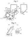
- Fig. 1(a)is an explanatory diagram showing a principal part of this embodiment, in which 61 denotes a developing equipment for red color to be replaceably mounted on a copier (not shown in this figure); 62A, a toner hopper for red color as an example of a cartridge which is replaceably mounted on the developing equipment 61; 63a and 63b, lead switches as an example of developing equipment detecting means which are installed on the wall 65 of the copier; 64a and 64b, magnetic material pieces as an example of developing equipment indicating means which turn on respective lead switches 63a and 63b, when the developing equipment 61 has been mounted on the copier (in the state of Fig.
- 65a and 65blead switches as an example of indication detecting means installed on the developing equipment 61; 66a and 66b, magnetic material pieces as an example of cartridge indicating means for turning lead switches 65a and 65b on, respectively, when the toner hopper 62A is mounted on the developing equipment 61 (in the state of Fig.
- 67a toner concentration sensor for detecting the toner concentration inside the developing equipment 61
- 68a toner supplementing roller for supplementing toner from the toner hopper 62A to the developing equipment 61
- 69a photoreceptor drum
- 70a developer roller for use in developing a static latent image by supplying toner to the surface of photoreceptor drum 69
- 71 and 72stirring rollers for mixing toner and carrier inside the developing equipment 61.
- 62Bdesignates a toner hopper for blue, on which a magnetic material piece 66a is provided.
- Fig. 2is an electric circuit diagram showing an essential part of the control circuit for the apparatus shown in Fig. 1(a), in which R represents series connected resistances which respectively connect lead switches 63a, 63b, 65a, 65b to power sources V; I0 1 and I0 2 , exclusive NOR circuits each of which out-puts 1, when respective two input signals are both 1 or both 0; A 1 , and A 2 , respectively AND circuits; S, a toner supply signal circuit which outputs 1, when the toner concentration sensor 67 (Fig. 1(a)) gives a value lower than the specified value; and M, a motor for turning the toner supply roller 68.
- Rrepresents series connected resistances which respectively connect lead switches 63a, 63b, 65a, 65b to power sources V
- I0 1 and I0 2exclusive NOR circuits each of which out-puts 1, when respective two input signals are both 1 or both 0
- a 1 , and A 2respectively AND circuits
- Sa toner supply signal circuit which outputs
- the toner inside the developing equipment 61 and the toner inside the toner hopper 62are judged to be of the same type, only when the lead switches 63a and 63b and the lead switches 65a and 65b are in the same on - off combination state. In this way, discrimination can be made between different four color toners.
- Fig. 3is a diagram corresponding to Fig. 1(a) showing another embodiment, in which in place of the replaceable red color toner hopper 62A in Fig. 1(a), a toner hopper 62C equipped with a replaceable red color toner cartridge 74 is integrally combined with a red color developing equipment 61. Further, in place of lead switches 65a, 65b installed on the red color developing equipment 61 in Fig. 1(a), there are installed lead switches 75a, 75b on the toner hopper 62C; in place of the magnetic material pieces 66a, 66b provided on the toner hopper 62A in Fig.
- a magnetism producing means exemplifying a cartridge indicating meansis provided in a part of a hollow container for housing a powder toner, so that the existence or type of a cartridge may be detected by sensing the magnetism coming from said magnetism producing means and, moreover, that the copying operation may be stopped so as to avoid producing reject.
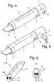
- Fig. 4is a perspective view of the whole of a cartridge.
- Both ends of a hollow cylinder 1 for housing powder toner in its interiorare closed with resin made covers 2, 3 and on the cover 2 there is provided a handle part 4 for turning the opening part 5a of the cartridge toward the toner supplying port of a developing section, after inserting the cartridge into the copier.
- the opening part 5ais sealed with a sealing member 5 which is to be stripped off, after the cartridge has been loaded in a copier.
- a magnetic card 6which enables the type, date of manufacture of the toner housed or the color, in the case of color toners, etc., to be written in.
- the position where the magnetic card is placedis where it is nearest to and facing a magnetic head 8 mounted on a copier, when the cartridge has been brought under its toner supplementing state by inserting it into the cartridge inserting part, as shown by an arrow 7.
- the information written into the magnetic card 6will be read out by the magnetic head 8, to conduct functions of a copier such as operation, stop and copying speed change, etc. Particularly, the operation of the copier may be stopped, as the case may be, lest unacceptable image be erroneously formed.
- a well-known mechanismwhich makes the indication as well as making the copier immovable, when no paper feeding cassette nor copying paper of the copier exists, is applicable.
- IC cardAs a means for providing a large capacity of memory storage on a small area, like magnetic card, IC card may be mentioned, besides it.
- characteristics of the toner to be stored on a magnetic card or IC cardthe production date, color of toner, and production related items such as guarantee period, manufacturing place, manufacturing machine, lot number, etc., or physical properties related items such as various specific gravities, grain size distribution, electric resistance, etc., may be mentioned.
- an indication detecting means provided on the copier side for reading out the IC carda well-known analyer is used.
- a compartmentis formed, to house a developer formed of a toner and a carrier.
- the existence of an appropriate toner cartridgeis detected by sensing the permeability of the developer with a magnetic sensor located on the side of the copier.
- a copieris of a structure such that a magnetic sensor called toner control sensor for keeping constant the toner concentration in the developer is provided in a developing apparatus, to make supplementation of toner, when the toner concentration has undergone a change (it normally declines).
- This embodimenttakes advantage of this phenomenon; thus, as shown in Fig. 5, a small container 9 is provided in a part of a cartridge, to house therein a developer consisting of a toner and a carrier being a magnetic body which ensures the best conditions for the copier.
- the specified placeis where it is brought to a neighborhood of and facing a permeability sensor 11 being an example of magnetic sensors mounted on a copier, when the toner supplementing state is brought about by loading a cartridge in the cartridge inserting section. If the permeability of the developer 10, as sensed by a permeability sensor 11, falls within the permissible range, as compared with the value of permeability which has been preset, the copier will be operated. If values outside this range are detected or no permeability is sensed, absence of an apropriate cartridge will be indicated by whatever means. The copier's operation is to be stopped, as the case may be, lest unacceptable image be erroneously prepared.
- the cartridge indicating means 22 shown in Fig. 6(a)is composed of a marker code 22' differentiated corresponding to the type of toner.
- This indication 22is stuck on the bottom wall 21a at the end part, as seen in its loading direction into the copier, not shown in this figure, of a cartridge 21 formed in a cylindrical shape and having on its side wall an opening 21' for supplying toner (sealed with a tape, when out of use).
- the indication detecting means 23is composed of a plurality of photoelectric reflection type sensors 23' as shown in Fig. 6(b). This indication detecting means 23 is provided at a position on the front of a cover 28. Such an indication detecting means 23 detects the type of the cartridge 21 through combination of output signals from a plurality of photoelectric reflection type sensors 23' which make on or off, corresponding to the marker code 22' of the cartridge 21, when loaded into the copier.
- the indication 22 of afore-mentioned embodiment and the indication detecting means 23may be composed of a printed pattern 22a and a CCD sensor 23a for detecting said pattern 22a (refer to Figs. 7(a) and (b).
- afore-mentioned patternthose differing in lightness or those with colors may be contemplated.
- the indication detecting means in afore-mentioned embodimentsphotosensors for detecting the light and shade or those for detecting colors may be employed.
Landscapes
- Physics & Mathematics (AREA)
- General Physics & Mathematics (AREA)
- Dry Development In Electrophotography (AREA)
- Control Or Security For Electrophotography (AREA)
- Electrophotography Configuration And Component (AREA)
Description
- The present invention relates to a system for making discriminations between cartridges for housing toners to be equipped on image forming apparatus such as electrostatic copiers, laser beam printers, facsimiles, etc.
- Supplementing toner into an image forming apparatus such as afore-mentioned is done in many cases with a cartridge housing toners therein (hereinafter merely referred to as cartridge) loaded in a cartridge inserting part of the image forming apparatus.
- Such a cartridge is sealed on its toner supplementing port with a flexible sheet folded in two plies. Accordingly, when supplementing the toner, this cartridge is loaded in the cartridge inserting part such as a toner hopper, etc., on the developing device side. Thereafter, the toner supplementing port is unsealed by stripping off the afore-mentioned flexible sheet by pulling its turned-up portion, thereby charging the toner into the toner hopper.
- Such a conventional toner supplementing device involved following problems:
- Conventional toner supplementing devices are of a structure such that even if the loading of a cartridge in a toner hopper is somewhat imperfect, the flexible sheet is strippable. For this reason, the toner supplementing port will be sometimes inadvertently unsealed, not withstanding the cartridge has not been properly loaded. As the consequence, the toner sometimes scatters through clearances. Particularly, during the image treating operation, the toner has sometimes been blown and leaked out due to the cooling air inside the image forming apparatus or the revolution of toner supplementing rollers, etc.
- Cartridges are often so composed as to have a common size, so that their components may be put to common use with different types of image forming apparatuses. Accordingly, when various types of image forming apparatuses are available, there has been a possibility of supplementing toners which are different in properties and color, etc.
- A cartridge discriminating system comprising cartridge indicating means provided on a toner cartridge, and indication detecting means cooperating with said cartridge indicating means to check the suitability of the type of the cartridge when the latter is inserted into a cartridge inserting part of an image forming apparatus is known from DE-A-34 15 291. In this prior system the cartridge indicating means is a flange provided on the toner cartridge, and the indication detecting means is a mating groove provided in a cartridge holder, so that only a cartridge having a flange at the proper position may be inserted into the cartridge holder.
- A toner cartridge having a sealing strip which is removably secured to the cartridge and which seals an opening in the surface of the cartridge to prevent discharge of toner particles is known from US-A-4 478 512.
- JP-A-61/59 364 discloses a copying machine in which units may be loaded or selectively attached to and detached from the copying machine body. To prevent a wrong unit from being loaded shield plates for different identification information are fitted to the units, and the information presented by the respective shield plate is read by a photosensor mounted on the copying machine body. If on the basis of the output of the photosensor the unit is found to be wrong, an alarm is triggered or the power supply is inhibited.
- Furthermore JP-A-61/156 165 discloses a cartridge discriminating system in which magnets are provided at four different locations of the side face of the cartridge housing and four reed switches are arranged at four different locations on a printer main body side so that the switches can face the magnets to thereby detect the respective cartridge.
- US-A-4 579 443 discloses an image forming apparatus having a developing unit which is divided into a first and a second developing device each of which includes a developing roller and both of which can be mounted to or removed from the main body of the image forming apparatus. The developing devices each are provided with a cap equipped with a color indicator which permits identification of the color of the developer stored inside the respective developing device.
- DE-A-3 524 506 discloses a toner cartridge having a color display unit which is composed of a selected transparent material of the same color as that of the toner stored inside the cartridge. The color display unit is installed at a position opposite to a transparent window so that it may be visually checked by an operator in order to identify both the condition and the color of the developer contained in the cartridge.
- An object of this invention is to provide for a cartridge discriminating system provided with a replaceable developing equipment, which system is adapted to check the suitability of the type of a cartridge inserted into the developing equipment, so that it becomes possible to supplement a toner of specified properties or color, thereby averting the trouble of allowing different types of toners to be mixed.
- According to the subject invention a cartridge discriminating system for an image forming apparatus which is provided with a replaceable developing equipment for supplying toner to a photoreceptor for developing static latent images, said cartridge discriminating system comprising cartridge indicating means provided on a toner cartridge, and indication detecting means provided on the image forming apparatus and cooperating with said cartridge indicating means for detecting said cartridge when the latter is inserted into a cartridge inserting part of the image forming apparatus is characterized by developing equipment indicating means provided on said developing equipment, developing equipment detecting means provided on the image forming apparatus and cooperating with said developing equipment indicating means for detecting said developing equipment when the latter is attached to the image forming apparatus, and means for checking the suitability of the type of the inserted cartridge by comparing an indication item detected by said indication detecting means with data detected by said developing equipment detecting means.
- Figs.1(a) and (b)
- are, respectively, diagrams for explanation of structure showing essential parts of a cartridge discriminating system of this invention;
- Fig. 2
- is an electric circuit diagram showing an essential part of a control circuit of the embodiment shown in Fig. 1;
- Fig. 3
- is a drawing corresponding to Fig. 1 illustrating a modification of the embodiment shown in Fig. 1;
- Fig. 4
- is a perspective view showing cartridge indicating means and indication detecting means adapted for use in the cartridge discriminating system embodying this invention;
- Fig. 5
- is a perspective view showing a modified embodiment of cartridge indicating means and indication detecting means;
- Figs.6(a) and (b)
- are, respectively, a perspective view of a cartridge equipped with a cartridge indicating means usable in the same embodiments and a front view of an indication detecting means capable of detecting said indicating means; and
- Figs.7(a) and (b)
- are, respectively, a perspective view of a cartridge equipped with a cartridge indicating means usable with a cartridge discriminating system of another embodiment and a front view of an indication detecting means capable of detecting said cartridge indicating means.
- In the following description of embodiments, a copier is explained as a typical example of image forming apparatuses. This invention is, of course, applicable to laser beam printers and facsimilies, and other image forming apparatuses.
- In the embodiment described hereunder, a data (indication) intrinsic to the developing device is attached to the developing equipment and this data and the indication attached to a cartridge are referenced to each other and when they are in agreement with each other, the state in which the toner supplementation is possible is evidenced.
- Thus this embodiment may be summarized as a cartridge discriminating system for an image forming apparatus replaceably equipped with a developing equipment for developing a static latent image by supplying toner to a photoreceptor, in which, while a cartridge indicating means is provided on a part of a cartridge for housing toner, a developing equipment indicating means is provided on a part of the developing equipment; and while an indication detecting means which detects the afore-mentioned cartridge indication means is provided on the image forming apparatus side, there is provided a developing equipment detecting means for detecting the afore-mentioned developing equipment, when the afore-mentioned developing equipment is attached to the image forming apparatus, so that when the cartridge is inserted into the cartridge inserting part of the image forming apparatus, the suitability of the type of the cartridge inserted may be detected by making a comparison between the indication data detected by the afore-mentioned indication detecting means and the data detected by the developing equipment detecting means.
- While this embodiment is described in iscriminating color toners color by color, it goes without saying that it is applicable to the discrimination of toners on a basis of their other characteristics, too.
- Fig. 1(a) is an explanatory diagram showing a principal part of this embodiment, in which 61 denotes a developing equipment for red color to be replaceably mounted on a copier (not shown in this figure); 62A, a toner hopper for red color as an example of a cartridge which is replaceably mounted on the developing equipment 61; 63a and 63b, lead switches as an example of developing equipment detecting means which are installed on the wall 65 of the copier; 64a and 64b, magnetic material pieces as an example of developing equipment indicating means which turn on respective lead switches 63a and 63b, when the developing equipment 61 has been mounted on the copier (in the state of Fig. 12(a)); 65a and 65b, lead switches as an example of indication detecting means installed on the developing equipment 61; 66a and 66b, magnetic material pieces as an example of cartridge indicating means for turning lead switches 65a and 65b on, respectively, when the toner hopper 62A is mounted on the developing equipment 61 (in the state of Fig. 12(a)); 67, a toner concentration sensor for detecting the toner concentration inside the developing equipment 61; 68, a toner supplementing roller for supplementing toner from the toner hopper 62A to the developing equipment 61; 69, a photoreceptor drum; 70, a developer roller for use in developing a static latent image by supplying toner to the surface of photoreceptor drum 69; and 71 and 72, stirring rollers for mixing toner and carrier inside the developing equipment 61. In Fig. 1(b), 62B designates a toner hopper for blue, on which a magnetic material piece 66a is provided.
- Fig. 2 is an electric circuit diagram showing an essential part of the control circuit for the apparatus shown in Fig. 1(a), in which R represents series connected resistances which respectively connect lead switches 63a, 63b, 65a, 65b to power sources V; I01 and I02, exclusive NOR circuits each of which out-puts 1, when respective two input signals are both 1 or both 0; A1, and A2, respectively AND circuits; S, a toner supply signal circuit which outputs 1, when the toner concentration sensor 67 (Fig. 1(a)) gives a value lower than the specified value; and M, a motor for turning the toner supply roller 68.
- In this composition, as the red color developing equipment 61 and the red color toner hopper 62A are installed in place, lead switches 63a, 63b and 65a, 65b are respectively turned on by the magnetic material pieces 64a, 64b and 66a, 66b, respectively facing them. Referring to Fig. 2, into the exclusive NOR circuits I01, I02 both 1 is inputted and both output 1. The AND circuit A1 outputs 1 and, then, when the toner supply signal circuit S outputs 1, the AND circuit A2 outputs 1; then, the motor M is driven, to let the toner supply roller 68 turn, until the toner supply signal circuit S outputs 0.
- However, when a blue color toner hopper 62B shown in Fig. 1(b) is mistakenly mounted on the red color developing equipment 61, the lead switch 65b is turned off, and the lead switches 63a, 63b and 65a, on; therefore, the exclusive NOR circuit I01outputs 1, but the exclusive NOR circuit I02 outputs 0. Accordingly, the output from the AND circuit A1 becomes 0, so that even when the toner supply signal circuit S outputs 1, the AND circuit A2 does not output 1; consequently, the motor M will not run; thus, no supply of toner from the blue color toner hopper 62B will take place.
- Thus in this embodiment, by the circuit shown in Fig. 2, the toner inside the developing equipment 61 and the toner inside the toner hopper 62 are judged to be of the same type, only when the lead switches 63a and 63b and the lead switches 65a and 65b are in the same on - off combination state. In this way, discrimination can be made between different four color toners.
- Fig. 3 is a diagram corresponding to Fig. 1(a) showing another embodiment, in which in place of the replaceable red color toner hopper 62A in Fig. 1(a), a toner hopper 62C equipped with a replaceable red color toner cartridge 74 is integrally combined with a red color developing equipment 61. Further, in place of lead switches 65a, 65b installed on the red color developing equipment 61 in Fig. 1(a), there are installed lead switches 75a, 75b on the toner hopper 62C; in place of the magnetic material pieces 66a, 66b provided on the toner hopper 62A in Fig. 12(a), magnetic material pieces 76a, 76b on the red color toner cartridge 74; and in place of the lead switches 63a, 63b installed on the wall surface 65 of the copier, DIP switches 73a, 73b preset in closed circuit state on the red color developing equipment 61.
- In this composition, when the developing equipment 61 and the toner cartridge 74 are respectively installed, as shown in Fig. 3, the control circuit of Fig. 2 will come into operation similarly as in the above-described embodiment.
- Further embodiments of the cartridge indicating and detecting means are described below with reference to Figs. 4 to 7.
- In the embodiment of Fig. 4 a magnetism producing means exemplifying a cartridge indicating means is provided in a part of a hollow container for housing a powder toner, so that the existence or type of a cartridge may be detected by sensing the magnetism coming from said magnetism producing means and, moreover, that the copying operation may be stopped so as to avoid producing reject.
- Fig. 4 is a perspective view of the whole of a cartridge.
- Both ends of a hollow cylinder 1 for housing powder toner in its interior are closed with resin made covers 2, 3 and on the cover 2 there is provided a handle part 4 for turning the opening part 5a of the cartridge toward the toner supplying port of a developing section, after inserting the cartridge into the copier. The opening part 5a is sealed with a sealing member 5 which is to be stripped off, after the cartridge has been loaded in a copier.
- In a part of the cartridge, a magnetic card 6 is provided which enables the type, date of manufacture of the toner housed or the color, in the case of color toners, etc., to be written in. The position where the magnetic card is placed is where it is nearest to and facing a magnetic head 8 mounted on a copier, when the cartridge has been brought under its toner supplementing state by inserting it into the cartridge inserting part, as shown by an arrow 7. The information written into the magnetic card 6 will be read out by the magnetic head 8, to conduct functions of a copier such as operation, stop and copying speed change, etc. Particularly, the operation of the copier may be stopped, as the case may be, lest unacceptable image be erroneously formed. For this purpose, a well-known mechanism which makes the indication as well as making the copier immovable, when no paper feeding cassette nor copying paper of the copier exists, is applicable.
- Further, as a means for providing a large capacity of memory storage on a small area, like magnetic card, IC card may be mentioned, besides it. As characteristics of the toner to be stored on a magnetic card or IC card, the production date, color of toner, and production related items such as guarantee period, manufacturing place, manufacturing machine, lot number, etc., or physical properties related items such as various specific gravities, grain size distribution, electric resistance, etc., may be mentioned. As an indication detecting means provided on the copier side for reading out the IC card, a well-known analyer is used.
- In the embodiment shown in Fig. 5, in part of a hollow container, a compartment is formed, to house a developer formed of a toner and a carrier. The existence of an appropriate toner cartridge is detected by sensing the permeability of the developer with a magnetic sensor located on the side of the copier.
- Generally, a copier is of a structure such that a magnetic sensor called toner control sensor for keeping constant the toner concentration in the developer is provided in a developing apparatus, to make supplementation of toner, when the toner concentration has undergone a change (it normally declines). This embodiment takes advantage of this phenomenon; thus, as shown in Fig. 5, a small container 9 is provided in a part of a cartridge, to house therein a developer consisting of a toner and a carrier being a magnetic body which ensures the best conditions for the copier.
- The specified place is where it is brought to a neighborhood of and facing a permeability sensor 11 being an example of magnetic sensors mounted on a copier, when the toner supplementing state is brought about by loading a cartridge in the cartridge inserting section. If the permeability of the developer 10, as sensed by a permeability sensor 11, falls within the permissible range, as compared with the value of permeability which has been preset, the copier will be operated. If values outside this range are detected or no permeability is sensed, absence of an apropriate cartridge will be indicated by whatever means. The copier's operation is to be stopped, as the case may be, lest unacceptable image be erroneously prepared. Accordingly, the well-known mechanism that makes indication or makes the copier inoperable, when no paper feeding cassette or copying paper of the copier exists will be usable. If such a permeability sensor 11 is used in common with an already installed permeability sensor for detecting the developer concentration inside the developing apparatus, reduction in cost will be further promoted.
- The cartridge indicating means 22 shown in Fig. 6(a) is composed of a marker code 22' differentiated corresponding to the type of toner. This indication 22 is stuck on the bottom wall 21a at the end part, as seen in its loading direction into the copier, not shown in this figure, of a cartridge 21 formed in a cylindrical shape and having on its side wall an opening 21' for supplying toner (sealed with a tape, when out of use).
- The indication detecting means 23 is composed of a plurality of photoelectric reflection type sensors 23' as shown in Fig. 6(b). This indication detecting means 23 is provided at a position on the front of a cover 28. Such an indication detecting means 23 detects the type of the cartridge 21 through combination of output signals from a plurality of photoelectric reflection type sensors 23' which make on or off, corresponding to the marker code 22' of the cartridge 21, when loaded into the copier.
- The indication 22 of afore-mentioned embodiment and the indication detecting means 23 (refer to Figs. 6(a) and (b)) may be composed of a printed pattern 22a and a CCD sensor 23a for detecting said pattern 22a (refer to Figs. 7(a) and (b). For the afore-mentioned pattern, those differing in lightness or those with colors may be contemplated. As the indication detecting means in afore-mentioned embodiments, photosensors for detecting the light and shade or those for detecting colors may be employed.
Claims (4)
- A cartridge discriminating system for an image forming apparatus which is provided with a replaceable developing equipment (61) for supplying toner to a photoreceptor (69) for developing static latent images said cartridge discriminating system comprising cartridge indicating means (6, 9, 22, 66a, 66b, 76a, 76b) provided on a toner cartridge (62A, 62B, 74), and indication detecting means (8, 11, 23, 65a, 65b, 75a, 75b) provided on the image forming apparatus and cooperating with said cartridge indicating means for detecting said cartridge when the latter is inserted into a cartridge inserting part of the developing equipment, characterized by developing equipment indicating means (64a, 64b, 73a, 73b) provided on said developing equipment (61), developing equipment detecting means (63a, 63b) provided on the image forming apparatus and cooperating with said developing equipment indicating means for detecting said developing equipment when the latter is attached to the image forming apparatus, and means (IO1, IO2, A1) for checking the suitability of the type of the inserted cartridge by comparing an indication item detected by said indication detecting means (65a, 65b, 75a, 75b) with data detected by said developing equipment detecting means (63a, 63b).
- A cartridge discriminating system as defined in claim 1, wherein said cartridge indicating and indication detecting means comprise pieces of magnetic material (66a, 66b, 76a, 76b) and lead switches (65a, 65b, 75a, 75b) adapted to be actuated by said pieces of magnetic material.
- A cartridige discriminating system as defined in claim 1 or 2, wherein said developing equipment indicating and detecting means comprises pieces of magnetic material (64a, 64b) and lead switches (63a, 63b, 73a, 73) adapted to be actuated bay said pieces of magnetic material.
- A cartridge discriminating system as defined in claim 1 wherein said cartridge indicating means is a magnetic card (6), an IC card, a small container (9) containing a developer of the same type as that of the toner and a carrier housed in the cartridge, or a mark (22) printed on said cartridge, and said indication detecting means is a magnetic head, an analyzer for reading out an IC card, a permeability sensor (11) for an optical sensor (23) for detecting a pattern, respectively.
Applications Claiming Priority (11)
| Application Number | Priority Date | Filing Date | Title |
|---|---|---|---|
| JP226383/86 | 1986-09-24 | ||
| JP61226383AJPH0642106B2 (en) | 1986-09-24 | 1986-09-24 | Toner supply device |
| JP228870/86 | 1986-09-27 | ||
| JP228871/86 | 1986-09-27 | ||
| JP61228870AJPS6382492A (en) | 1986-09-27 | 1986-09-27 | Copying machine |
| JP61228871AJPS6382493A (en) | 1986-09-27 | 1986-09-27 | Copying machine |
| JP228869/86 | 1986-09-27 | ||
| JP61228869AJPS6382491A (en) | 1986-09-27 | 1986-09-27 | Copying machine |
| JP234104/86 | 1986-09-30 | ||
| JP61234104AJPS6385771A (en) | 1986-09-30 | 1986-09-30 | Copying device |
| EP87113843AEP0261643B1 (en) | 1986-09-24 | 1987-09-22 | Cartridge discriminating system |
Related Parent Applications (1)
| Application Number | Title | Priority Date | Filing Date |
|---|---|---|---|
| EP87113843.4Division | 1987-09-22 |
Publications (3)
| Publication Number | Publication Date |
|---|---|
| EP0478019A2 EP0478019A2 (en) | 1992-04-01 |
| EP0478019A3 EP0478019A3 (en) | 1992-04-22 |
| EP0478019B1true EP0478019B1 (en) | 1997-07-30 |
Family
ID=27529799
Family Applications (2)
| Application Number | Title | Priority Date | Filing Date |
|---|---|---|---|
| EP87113843AExpired - LifetimeEP0261643B1 (en) | 1986-09-24 | 1987-09-22 | Cartridge discriminating system |
| EP91122030AExpired - LifetimeEP0478019B1 (en) | 1986-09-24 | 1987-09-22 | Cartridge discriminating system |
Family Applications Before (1)
| Application Number | Title | Priority Date | Filing Date |
|---|---|---|---|
| EP87113843AExpired - LifetimeEP0261643B1 (en) | 1986-09-24 | 1987-09-22 | Cartridge discriminating system |
Country Status (3)
| Country | Link |
|---|---|
| US (1) | US4963939A (en) |
| EP (2) | EP0261643B1 (en) |
| DE (2) | DE3752095T2 (en) |
Families Citing this family (68)
| Publication number | Priority date | Publication date | Assignee | Title |
|---|---|---|---|---|
| US5184181A (en)* | 1986-09-24 | 1993-02-02 | Mita Industrial Co., Ltd. | Cartridge discriminating system |
| US5075724A (en)* | 1988-08-26 | 1991-12-24 | Minolta Camera Kabushiki Kaisha | System for recognizing interchangeable articles |
| JP2691914B2 (en)* | 1988-09-09 | 1997-12-17 | 株式会社リコー | Image forming device |
| JP2965041B2 (en)* | 1988-11-08 | 1999-10-18 | 株式会社リコー | Image forming device |
| AU106776S (en) | 1989-01-12 | 1990-02-12 | Canon Kk | Toner container for photo-copier |
| US5218409A (en)* | 1989-09-19 | 1993-06-08 | Sanyo Electric Co., Ltd. | Image forming apparatus |
| JP2985205B2 (en)* | 1990-01-25 | 1999-11-29 | ミノルタ株式会社 | Image forming device |
| JPH07119144B2 (en)* | 1991-05-17 | 1995-12-20 | 富士ゼロックス株式会社 | Laser beam printer |
| EP0571767B1 (en)* | 1992-05-26 | 1997-09-10 | Konica Corporation | Image-forming apparatus |
| JP3157610B2 (en)* | 1992-06-30 | 2001-04-16 | キヤノン株式会社 | Process cartridge and image forming apparatus |
| US5289242A (en)* | 1992-11-17 | 1994-02-22 | Hewlett-Packard | Method and system for identifying the type of toner print cartridges loaded into electrophotographic printers |
| US5261326A (en)* | 1993-04-06 | 1993-11-16 | Michlin Steven B | Method to modify a printer cartridge to function in a fax machine |
| USD363305S (en) | 1993-05-26 | 1995-10-17 | Mita Industrial Co., Ltd. | Toner cartridge |
| US5559589A (en)* | 1993-09-27 | 1996-09-24 | Compaq Computer Corporation | Keying method and apparatus |
| KR0153420B1 (en)* | 1993-12-31 | 1998-12-15 | 김광호 | Consumable parts locking device and method by identification code in image forming apparatus |
| USD362678S (en) | 1994-03-02 | 1995-09-26 | Canon Kabushiki Kaisha | Toner cartridge for copying machine |
| AU128550S (en) | 1995-03-28 | 1996-11-08 | Canon Kk | Toner cartridge |
| JP3363680B2 (en)* | 1995-12-28 | 2003-01-08 | ブラザー工業株式会社 | Cartridge authenticity discrimination method and output device using the same |
| JPH09213407A (en)* | 1996-01-31 | 1997-08-15 | Canon Inc | Connector, unit, process cartridge, and electrophotographic image forming apparatus |
| US5749026A (en)* | 1996-02-13 | 1998-05-05 | Rti International Corporation | Removable shipping seal for a toner cartridge and method of using the same |
| USD399870S (en) | 1996-08-23 | 1998-10-20 | Mita Industrial Co., Ltd. | Toner cartridge |
| US6097405A (en)* | 1996-09-30 | 2000-08-01 | Hewlett-Packard Company | Detection apparatus and method for use in a printing device |
| US5877798A (en)* | 1997-03-21 | 1999-03-02 | Lexmark International Inc. | Method and apparatus for automatically determining the style printhead installed in a laser printer |
| US6106089A (en)* | 1997-04-30 | 2000-08-22 | Eastman Kodak Company | Magnetic sensor for ink detection |
| US5807005A (en)* | 1997-05-12 | 1998-09-15 | Lexmark International, Inc. | Cartridge lockout system and method |
| JPH1124530A (en)* | 1997-07-04 | 1999-01-29 | Oki Data:Kk | Image forming device |
| AU3969299A (en)* | 1998-05-01 | 1999-11-23 | Clarity Imaging Technologies, Inc. | Removable shipping seal for a toner cartridge |
| US5995774A (en)* | 1998-09-11 | 1999-11-30 | Lexmark International, Inc. | Method and apparatus for storing data in a non-volatile memory circuit mounted on a printer's process cartridge |
| US6324350B1 (en) | 1998-12-25 | 2001-11-27 | Casio Computer Co., Ltd. | Reusable unit displaying a specific pattern and an image forming apparatus using the reusable unit when the specific pattern is displayed and rendering the specific pattern illegible when the reusable unit is exhausted |
| JP3871460B2 (en) | 1999-01-29 | 2007-01-24 | 株式会社沖データ | Cartridge, method for manufacturing the same, and image forming apparatus |
| JP2000321837A (en)* | 1999-05-12 | 2000-11-24 | Fuji Xerox Co Ltd | Mechanism for discriminating process cartridge |
| JP2000321946A (en)* | 1999-05-14 | 2000-11-24 | Matsushita Graphic Communication Systems Inc | Recorder, process cartridge used therefor, cartridge discriminating method and image communication device |
| JP3050872B1 (en)* | 1999-07-12 | 2000-06-12 | 松下電送システム株式会社 | Transfer unit and recording device having the same |
| JP3522608B2 (en)* | 1999-08-03 | 2004-04-26 | シャープ株式会社 | Replacement part recognition device and image forming device |
| US6249654B1 (en)* | 1999-09-29 | 2001-06-19 | Xerox Corporation | Refillable all-in-one print cartridge/toner bottle strategy |
| US6266506B1 (en)* | 1999-09-29 | 2001-07-24 | Xerox Corporation | Mechanical keying concept for refillable print cartridge/toner bottle strategy |
| US6263170B1 (en) | 1999-12-08 | 2001-07-17 | Xerox Corporation | Consumable component identification and detection |
| US6334037B1 (en) | 2000-02-18 | 2001-12-25 | Toshiba Tec Kabushiki Kaisha | Image forming apparatus |
| US6240262B1 (en)* | 2000-02-18 | 2001-05-29 | Toshiba Tec Kabushiki Kaisha | Toner supply device and toner cartridge |
| US6289182B1 (en)* | 2000-02-18 | 2001-09-11 | Toshiba Tec Kabushiki Kaisha | Method and apparatus for discriminating toner bottle types, stirring toner, and detecting the amount of remaining toner |
| US6256469B1 (en)* | 2000-02-18 | 2001-07-03 | Toshiba Tec Kabushiki Kaisha | Toner supply apparatus in image forming system |
| US6398335B1 (en)* | 2000-03-31 | 2002-06-04 | Hewlett-Packard Company | Magnetic connection of ink-jet printer components |
| CA2350397C (en) | 2000-06-16 | 2006-01-10 | Canon Kabushiki Kaisha | Solid semiconductor element, ink tank, ink jet recording apparatus provided with ink tank, liquid information acquiring method and liquid physical property change discriminating method |
| US6473571B1 (en)* | 2000-10-02 | 2002-10-29 | Xerox Corporation | Communicating dispensing article |
| US7133144B2 (en)* | 2001-07-26 | 2006-11-07 | International Business Machines Corporation | Closed loop feedback system for alternative toners |
| GB2383500A (en)* | 2002-10-01 | 2003-06-25 | Flying Null Ltd | Verifying the authenticity and determining the correct connection of an attachable component using a tag and modifying the operation of the apparatus |
| JP3778110B2 (en)* | 2002-03-19 | 2006-05-24 | 富士ゼロックス株式会社 | Wireless communication system, image forming apparatus, and cartridge part |
| US7133629B2 (en)* | 2002-04-12 | 2006-11-07 | Ricoh Company, Ltd. | Image forming method and apparatus including as easy-to-handle large capacity toner container |
| JP4194298B2 (en) | 2002-05-17 | 2008-12-10 | キヤノン株式会社 | Information storage medium, unit, process cartridge, developing cartridge, and electrophotographic image forming apparatus |
| JP4147832B2 (en)* | 2002-06-17 | 2008-09-10 | 富士ゼロックス株式会社 | Wireless communication system, image forming apparatus, and cartridge part |
| US6766119B2 (en)* | 2002-12-16 | 2004-07-20 | Kabushiki Kaisha Toshiba | Toner cartridge identifying apparatus for an image forming apparatus |
| US6895191B2 (en)* | 2003-05-13 | 2005-05-17 | Xerox Corporation | Insertion verification of replaceable module of printing apparatus |
| JPWO2005008343A1 (en)* | 2003-07-17 | 2006-09-07 | 富士通株式会社 | Consumables detection device, consumables detection method, consumables detection program, and image forming apparatus |
| WO2005074999A1 (en) | 2004-02-03 | 2005-08-18 | S.C. Johnson & Son, Inc. | Device providing coordinated emission of light and volatile active |
| US7824627B2 (en) | 2004-02-03 | 2010-11-02 | S.C. Johnson & Son, Inc. | Active material and light emitting device |
| US7350720B2 (en) | 2004-02-03 | 2008-04-01 | S.C. Johnson & Son, Inc. | Active material emitting device |
| WO2006013621A1 (en) | 2004-08-03 | 2006-02-09 | Fujitsu Limited | Device configuration recognition system, configuration recognition method, and configuration recognition program |
| JP2006078817A (en)* | 2004-09-10 | 2006-03-23 | Ricoh Co Ltd | Developing device, process cartridge, and image forming apparatus |
| JP4118277B2 (en)* | 2005-01-24 | 2008-07-16 | シャープ株式会社 | Toner supply device |
| US20060279127A1 (en)* | 2005-06-09 | 2006-12-14 | Cronin John E | Apparatus including a selective interface system between two sub-components |
| CN200984099Y (en)* | 2005-12-21 | 2007-12-05 | 皇家飞利浦电子股份有限公司 | Cylinder for prepairng beverage, machine for prepairng beverage and system for prepairng beverage |
| JP4844237B2 (en)* | 2006-05-25 | 2011-12-28 | 富士ゼロックス株式会社 | Toner container and toner filling method |
| BR112013011242A2 (en)* | 2010-11-11 | 2016-11-01 | Nestec S A Ch | capsule, beverage production machine and system for preparing a nutritional product |
| US8892008B2 (en)* | 2013-03-12 | 2014-11-18 | Xerox Corporation | Method and apparatus for reducing residual toner in a rotating container |
| EP3093714A4 (en)* | 2014-01-10 | 2017-07-26 | Ricoh Company, Ltd. | Image forming device |
| US20150257586A1 (en)* | 2014-03-11 | 2015-09-17 | Starbucks Corporation Dba Starbucks Coffee Company | Single-serve beverage production machine |
| KR20200025336A (en)* | 2018-08-30 | 2020-03-10 | 휴렛-팩커드 디벨롭먼트 컴퍼니, 엘.피. | Structure for selectively locking toner inlet shutter of toner refill portion |
| JP7205331B2 (en)* | 2019-03-20 | 2023-01-17 | 株式会社リコー | Image forming apparatus, image forming method, and program |
Family Cites Families (15)
| Publication number | Priority date | Publication date | Assignee | Title |
|---|---|---|---|---|
| US3385500A (en)* | 1966-04-29 | 1968-05-28 | Xerox Corp | Toner package |
| US4371015A (en)* | 1980-12-24 | 1983-02-01 | Tbs, Inc. | Toner loading system having cartridge with displaceable diaphragm |
| US4611899A (en)* | 1983-01-08 | 1986-09-16 | Canon Kabushiki Kaisha | Developing apparatus |
| US4478512A (en)* | 1983-05-11 | 1984-10-23 | Xerox Corporation | Toner cartridge for use in an electrophotographic printing machine |
| JPS60107955U (en)* | 1983-12-26 | 1985-07-23 | シャープ株式会社 | Copy machine |
| JPS60146265A (en)* | 1984-01-09 | 1985-08-01 | Ricoh Co Ltd | Toner replenishment device for dry copying machines |
| JPS60229046A (en)* | 1984-04-27 | 1985-11-14 | Toshiba Corp | Image forming device |
| JPS6119260U (en)* | 1984-07-09 | 1986-02-04 | シャープ株式会社 | Copy machine cartridge loading device |
| JPS6156370A (en)* | 1984-08-28 | 1986-03-22 | Ricoh Co Ltd | Image forming device |
| JPS6159364A (en)* | 1984-08-31 | 1986-03-26 | Ricoh Co Ltd | Copy machine |
| JPS6183551A (en)* | 1984-10-01 | 1986-04-28 | Mitsubishi Electric Corp | copying device |
| JPS61132969A (en)* | 1984-11-30 | 1986-06-20 | Ricoh Co Ltd | Color recording device |
| JPS61156165A (en)* | 1984-12-28 | 1986-07-15 | Toshiba Corp | Image forming device |
| US4768055A (en)* | 1986-06-17 | 1988-08-30 | Mita Industrial Co., Ltd. | Image forming machine having a toner recycling unit |
| GB2269862B (en)* | 1992-08-22 | 1996-05-08 | Glacier Metal Co Ltd | Electromagnetic bearing arrangement |
- 1987
- 1987-09-21USUS07/099,118patent/US4963939A/ennot_activeExpired - Fee Related
- 1987-09-22DEDE3752095Tpatent/DE3752095T2/ennot_activeExpired - Fee Related
- 1987-09-22DEDE8787113843Tpatent/DE3782790T2/ennot_activeExpired - Fee Related
- 1987-09-22EPEP87113843Apatent/EP0261643B1/ennot_activeExpired - Lifetime
- 1987-09-22EPEP91122030Apatent/EP0478019B1/ennot_activeExpired - Lifetime
Also Published As
| Publication number | Publication date |
|---|---|
| DE3782790T2 (en) | 1993-04-08 |
| DE3752095D1 (en) | 1997-09-04 |
| EP0478019A2 (en) | 1992-04-01 |
| DE3782790D1 (en) | 1993-01-07 |
| EP0261643B1 (en) | 1992-11-25 |
| US4963939A (en) | 1990-10-16 |
| EP0261643A3 (en) | 1988-06-01 |
| EP0478019A3 (en) | 1992-04-22 |
| DE3752095T2 (en) | 1998-02-05 |
| EP0261643A2 (en) | 1988-03-30 |
Similar Documents
| Publication | Publication Date | Title |
|---|---|---|
| EP0478019B1 (en) | Cartridge discriminating system | |
| US5184181A (en) | Cartridge discriminating system | |
| US5021828A (en) | Copying apparatus having a consumable part | |
| US4265440A (en) | Computer-controlled paper feeder | |
| EP0598186B1 (en) | System for identifying the type of toner print cartridges loaded into electrophotographic printers | |
| EP0227242B1 (en) | Image forming apparatus | |
| US7477853B2 (en) | Toner cartridge having machine readable authentication pattern and image forming apparatus for reading the same | |
| US5053814A (en) | Image forming apparatus | |
| US5392102A (en) | Developing device having toner cartridge discriminator | |
| US7162190B2 (en) | Toner feeder | |
| US5666586A (en) | Apparatus for installing a toner cartridge | |
| CN114690601A (en) | Image forming apparatus | |
| US6941082B2 (en) | Replaceable toner cartridge for use with an image forming apparatus | |
| US6850715B2 (en) | Image forming apparatus with developer detector | |
| US5510884A (en) | Supply accessory for a printing machine with hidden identifier | |
| US4955317A (en) | Image forming apparatus having a plurality of developing units each containing two-component developer | |
| JP2813262B2 (en) | Image forming device | |
| US5148221A (en) | Image forming apparatus with toner density control based on the medium supplied | |
| JP3661740B2 (en) | Developing device and developer cartridge | |
| JPH01200272A (en) | Identifying device for cartridge provided with photosensitive body | |
| US5012283A (en) | Copying apparatus having a lamp to form or erase an image | |
| JP2001056607A (en) | Developing device and image forming device using the same | |
| JP2001249598A (en) | Office electronic equipment, temperature history detecting means thereof, and temperature history detecting method | |
| JPH02160262A (en) | Color image forming device | |
| JPH0232370A (en) | Managing device for service life of consumables |
Legal Events
| Date | Code | Title | Description |
|---|---|---|---|
| PUAI | Public reference made under article 153(3) epc to a published international application that has entered the european phase | Free format text:ORIGINAL CODE: 0009012 | |
| PUAL | Search report despatched | Free format text:ORIGINAL CODE: 0009013 | |
| AC | Divisional application: reference to earlier application | Ref document number:261643 Country of ref document:EP | |
| AK | Designated contracting states | Kind code of ref document:A2 Designated state(s):DE FR GB IT NL | |
| AK | Designated contracting states | Kind code of ref document:A3 Designated state(s):DE FR GB IT NL | |
| 17P | Request for examination filed | Effective date:19920716 | |
| 17Q | First examination report despatched | Effective date:19940414 | |
| APAB | Appeal dossier modified | Free format text:ORIGINAL CODE: EPIDOS NOAPE | |
| GRAG | Despatch of communication of intention to grant | Free format text:ORIGINAL CODE: EPIDOS AGRA | |
| GRAH | Despatch of communication of intention to grant a patent | Free format text:ORIGINAL CODE: EPIDOS IGRA | |
| GRAH | Despatch of communication of intention to grant a patent | Free format text:ORIGINAL CODE: EPIDOS IGRA | |
| GRAA | (expected) grant | Free format text:ORIGINAL CODE: 0009210 | |
| AC | Divisional application: reference to earlier application | Ref document number:261643 Country of ref document:EP | |
| AK | Designated contracting states | Kind code of ref document:B1 Designated state(s):DE FR GB IT NL | |
| PG25 | Lapsed in a contracting state [announced via postgrant information from national office to epo] | Ref country code:NL Free format text:LAPSE BECAUSE OF FAILURE TO SUBMIT A TRANSLATION OF THE DESCRIPTION OR TO PAY THE FEE WITHIN THE PRESCRIBED TIME-LIMIT Effective date:19970730 | |
| REF | Corresponds to: | Ref document number:3752095 Country of ref document:DE Date of ref document:19970904 | |
| PGFP | Annual fee paid to national office [announced via postgrant information from national office to epo] | Ref country code:DE Payment date:19970908 Year of fee payment:11 | |
| PGFP | Annual fee paid to national office [announced via postgrant information from national office to epo] | Ref country code:GB Payment date:19970915 Year of fee payment:11 | |
| ET | Fr: translation filed | ||
| PGFP | Annual fee paid to national office [announced via postgrant information from national office to epo] | Ref country code:FR Payment date:19970926 Year of fee payment:11 | |
| ITF | It: translation for a ep patent filed | ||
| NLV1 | Nl: lapsed or annulled due to failure to fulfill the requirements of art. 29p and 29m of the patents act | ||
| PLBE | No opposition filed within time limit | Free format text:ORIGINAL CODE: 0009261 | |
| STAA | Information on the status of an ep patent application or granted ep patent | Free format text:STATUS: NO OPPOSITION FILED WITHIN TIME LIMIT | |
| 26N | No opposition filed | ||
| PG25 | Lapsed in a contracting state [announced via postgrant information from national office to epo] | Ref country code:GB Free format text:LAPSE BECAUSE OF NON-PAYMENT OF DUE FEES Effective date:19980922 | |
| GBPC | Gb: european patent ceased through non-payment of renewal fee | Effective date:19980922 | |
| PG25 | Lapsed in a contracting state [announced via postgrant information from national office to epo] | Ref country code:FR Free format text:LAPSE BECAUSE OF NON-PAYMENT OF DUE FEES Effective date:19990531 | |
| PG25 | Lapsed in a contracting state [announced via postgrant information from national office to epo] | Ref country code:DE Free format text:LAPSE BECAUSE OF NON-PAYMENT OF DUE FEES Effective date:19990701 | |
| REG | Reference to a national code | Ref country code:FR Ref legal event code:ST | |
| PG25 | Lapsed in a contracting state [announced via postgrant information from national office to epo] | Ref country code:IT Free format text:LAPSE BECAUSE OF NON-PAYMENT OF DUE FEES Effective date:20050922 |