EP0477753B1 - A previous channel feature in a television receiver having multiple RF inputs - Google Patents
A previous channel feature in a television receiver having multiple RF inputsDownload PDFInfo
- Publication number
- EP0477753B1 EP0477753B1EP91115824AEP91115824AEP0477753B1EP 0477753 B1EP0477753 B1EP 0477753B1EP 91115824 AEP91115824 AEP 91115824AEP 91115824 AEP91115824 AEP 91115824AEP 0477753 B1EP0477753 B1EP 0477753B1
- Authority
- EP
- European Patent Office
- Prior art keywords
- tuning
- signals
- signal
- data
- input terminals
- Prior art date
- Legal status (The legal status is an assumption and is not a legal conclusion. Google has not performed a legal analysis and makes no representation as to the accuracy of the status listed.)
- Expired - Lifetime
Links
- 230000004044responseEffects0.000claims7
- 101710102715ADP/ATP translocase 3Proteins0.000description6
- 102100026397ADP/ATP translocase 3Human genes0.000description6
- 101710148586ADP,ATP carrier protein 1Proteins0.000description4
- 101710111394ADP,ATP carrier protein 1, mitochondrialProteins0.000description4
- 101710102716ADP/ATP translocase 1Proteins0.000description4
- 102100032533ADP/ATP translocase 1Human genes0.000description4
- 208000033986Device capturing issueDiseases0.000description4
- 238000003825pressingMethods0.000description4
- 101710148588ADP,ATP carrier protein 2Proteins0.000description3
- 101710165307ADP,ATP carrier protein 2, mitochondrialProteins0.000description3
- 101710102718ADP/ATP translocase 2Proteins0.000description3
- 230000005236sound signalEffects0.000description3
- 230000006870functionEffects0.000description2
- 239000002131composite materialSubstances0.000description1
- 230000001419dependent effectEffects0.000description1
- 230000000994depressogenic effectEffects0.000description1
- 238000010586diagramMethods0.000description1
- 230000000694effectsEffects0.000description1
- 244000145841kineSpecies0.000description1
- 238000004519manufacturing processMethods0.000description1
- 238000000034methodMethods0.000description1
Images


Classifications
- H—ELECTRICITY
- H03—ELECTRONIC CIRCUITRY
- H03J—TUNING RESONANT CIRCUITS; SELECTING RESONANT CIRCUITS
- H03J1/00—Details of adjusting, driving, indicating, or mechanical control arrangements for resonant circuits in general
- H03J1/0008—Details of adjusting, driving, indicating, or mechanical control arrangements for resonant circuits in general using a central processing unit, e.g. a microprocessor
- H03J1/0091—Details of adjusting, driving, indicating, or mechanical control arrangements for resonant circuits in general using a central processing unit, e.g. a microprocessor provided with means for scanning over a band of frequencies
- H—ELECTRICITY
- H04—ELECTRIC COMMUNICATION TECHNIQUE
- H04N—PICTORIAL COMMUNICATION, e.g. TELEVISION
- H04N21/00—Selective content distribution, e.g. interactive television or video on demand [VOD]
- H04N21/40—Client devices specifically adapted for the reception of or interaction with content, e.g. set-top-box [STB]; Operations thereof
- H04N21/41—Structure of client; Structure of client peripherals
- H04N21/422—Input-only peripherals, i.e. input devices connected to specially adapted client devices, e.g. global positioning system [GPS]
- H04N21/42204—User interfaces specially adapted for controlling a client device through a remote control device; Remote control devices therefor
- H04N21/42206—User interfaces specially adapted for controlling a client device through a remote control device; Remote control devices therefor characterized by hardware details
- H04N21/4221—Dedicated function buttons, e.g. for the control of an EPG, subtitles, aspect ratio, picture-in-picture or teletext
- H—ELECTRICITY
- H04—ELECTRIC COMMUNICATION TECHNIQUE
- H04N—PICTORIAL COMMUNICATION, e.g. TELEVISION
- H04N21/00—Selective content distribution, e.g. interactive television or video on demand [VOD]
- H04N21/40—Client devices specifically adapted for the reception of or interaction with content, e.g. set-top-box [STB]; Operations thereof
- H04N21/41—Structure of client; Structure of client peripherals
- H04N21/426—Internal components of the client ; Characteristics thereof
- H04N21/42607—Internal components of the client ; Characteristics thereof for processing the incoming bitstream
- H04N21/4263—Internal components of the client ; Characteristics thereof for processing the incoming bitstream involving specific tuning arrangements, e.g. two tuners
- H—ELECTRICITY
- H04—ELECTRIC COMMUNICATION TECHNIQUE
- H04N—PICTORIAL COMMUNICATION, e.g. TELEVISION
- H04N21/00—Selective content distribution, e.g. interactive television or video on demand [VOD]
- H04N21/40—Client devices specifically adapted for the reception of or interaction with content, e.g. set-top-box [STB]; Operations thereof
- H04N21/47—End-user applications
- H04N21/482—End-user interface for program selection
- H—ELECTRICITY
- H04—ELECTRIC COMMUNICATION TECHNIQUE
- H04N—PICTORIAL COMMUNICATION, e.g. TELEVISION
- H04N5/00—Details of television systems
- H04N5/44—Receiver circuitry for the reception of television signals according to analogue transmission standards
Definitions
- the subject applicationconcerns the field of television receivers having memory circuitry for storing lists of preferred television channels, and in particular, for storing multiple lists, wherein each list relates to a respective one of a plurality of RF signal sources.
- a television receiver as set out in the preambles of claims 1 and 5is disclosed in US-A-4 888 819.
- RF signal sourcesare currently available for supplying television signals to a user's television receiver. These RF signal sources include, an ultra-high frequency (UHF) antenna, a very-high frequency (VHF) antenna, video games, home computers, cable television systems, videocassette recorders, videodisc players, and TVRO (television receive-only) satellite television receivers.
- UHFultra-high frequency
- VHFvery-high frequency
- a television receiver with two RF signal input terminalseliminates repeated plugging-in and unplugging of cables which would otherwise be necessary when changing from one signal source to another.
- Such scan listsinclude information as to whether or not the desired channel is an "AIR" channel or a “CABLE” channel, information concerning the tuning voltage required to tune the channel, and information indicating in which band of frequencies the desired channel resides.
- a usercan program into the scan list only those channels which are of interest to him, thereby causing the "skipping" of unused, or undesired channels when changing channels via a "channel up", or “channel down” command. Scanning down beyond the last channel stored in the scan list causes the tuning of the first channel in the scan list.
- scanning up beyond the first channel stored in the scan listcauses the tuning of the last channel in the scan list.
- This method of operationis known as "wrapping around" from top to bottom or, bottom to top.
- Inclusion of a scan list feature in a television receiver having multiple RF input terminalsis known from the RCA CTC-133 color television receiver, manufactured by Thomson Consumer Electronics, Inc., Indianapolis, Indiana, U.S.A. In this receiver, each RF input terminal has a separate scan list associated with it.
- Each scan list of the above-mentioned CTC-133 television chassishas a "Last Tuned Channel” register associated with it for maintaining a record of the last-tuned channel from its associated RF input terminal.
- the last-tuned channel informationis used to retune the last-tuned channel when a user operates a "previous channel” (PC) key on his remote control unit.
- PCpreviously channel
- a usermay be confused by operation of the PC key according to the CTC-133 system because operation of the PC key of that television receiver will not cause the tuning of a previously tuned channel from an RF input other than the currently selected RF input.
- a Previous Channel and RF Input registerIn a television receiver including a plurality of RF input terminals, each of which having a respective scan list, and each scan list having an associated Last Tuned Channel register, and having a common Current Channel register, there is provided a Previous Channel and RF Input register.
- the Previous Channel and RF Input register and the Current Channel registerboth hold tuning information and RF Input terminal information which allow retuning of a formerly tuned channel regardless of which RF input provides the signal for that channel.
- the scan listsare linked providing an easy way to scan through the channels of all scan lists, and an easy return to a previously tuned channel from any RF input via operation of a Previous Channel (PC) key.
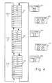
- FIGURE 1shows, in block diagram form, a television receiver incorporating the subject invention.
- FIGURES 2shows a keyboard suitable for use with the remote control handunit of FIGURE 1.
- FIGURE 3Ashows an arrangement of memory locations for storing scan lists and associated registers, as known from the prior art.
- FIGURES 3B and 4show arrangements of memory locations for storing scan lists and associated registers, in accordance with the subject invention.
- FIGURE 5is a flowchart showing a portion of the control program of the controller of FIGURE 1.
- radio frequency (RF) signalsare applied to RF input terminals A, B, and C of RF switch 100.
- RF switch 100selects one of inputs A, B, and C to supply one or more RF signals to a tuner assembly 102.
- Tuner assembly 102selects a particular RF signal under control of a tuner control unit 104 which applies a tuning control signal to tuner assembly 102 via a wire 103, and applies bandswitching signals via a control bus 103'.
- Tuner control unit 104is controlled by a controller 110.
- Controller 110which may be a microprocessor or microcomputer, includes a central processing unit (CPU) 112, a read-only memory (ROM) 114, and a random access memory 116. Controller 110 generates the above-mentioned control signal for RF switch 100 for selecting an RF input for tuner 102. Controller 110 receives user-entered control signals from a local keyboard 120 and from an infrared (IR) receiver 122. IR receiver 122 receives and decodes remote control signals transmitted by a remote control unit 125.
- IRinfrared
- Tuner 102produces a signal at an intermediate frequency (IF) and applies it to a processing unit 130 comprising a video IF (VIF) amplifying stage, an AFT circuit, a video detector, and a sound IF (SIF) amplifying stage.
- Processing unit 130produces a baseband composite video signal (TV), and a sound carrier signal.
- the sound carrier signalis applied to an audio signal processor unit 135 which includes an audio detector and a stereo decoder. Audio signal processor unit 135 produces baseband left and right audio signals and applies them a pair of speakers 138 for sound reproduction.
- the baseband video signal(TV) is coupled to a video processor unit 155 and a kine driver amplifier 156, and ultimately displayed on a display screen of a display device 158.
- Video signalsare also applied to a sync separator unit 160 which derives vertical and horizontal synchronizing signals therefrom.
- the derived vertical and horizontal signalsare applied to a deflection unit 170 for the production of deflection signals for application to the yoke assembly of display device 158.
- an on-screen display processor 140Under control of controller 110, an on-screen display processor 140 generates character signals, and applies them to a second input of video signal processor 155, for display on display device 158.
- the circuitry described thus faris known from the above-mentioned RCA CTC-133 color television chassis.
- a keyboard 200 suitable for use on remote control unit 125 of FIGURE 1includes a VOLUME DOWN key 210, a VOLUME UP key 220, an ON/OFF key 230, a CHANNEL DOWN key 240, a CHANNEL UP key 250, a Previous Channel (PC) key 265, a MENU - key 260, a MENU + key 270, an array of numbered keys generally designated 280, and a group of ANTENNA SELECT keys 275, 285, and 295.
- PCPrevious Channel
- the RCA CTC-133 color television chassisincludes three RF input connectors, each having a respective scan list associated with it.
- these scan listscan be thought of as being arranged in memory (i.e., RAM 116) as shown in FIGURE 3A.
- Each scan listis independent of the others.
- Each scan listhas its own pointer, which upon reaching the bottom of the scan list while scanning down, "wraps around" to the top, and which upon reaching the top of the scan list while scanning up, “wraps around” to the bottom.
- scan lists 315, 325, and 335are shown as including 32 (i.e., A0-A31) memory locations each. Also for simplicity, the "wrap around" arrows are shown extending between locations A0 and A31.
- a scan list having only three locations filledwould "wrap around" between location A2 (i.e., the third location in the list) and location A0. That is, the logical end of the scan list is not necessarily the same memory location as the physical end of the scan list. Note that in the prior art system of FIGURE 3A, a user must first select the scan list containing the desired channel information, and then conduct a search for the desired channel. A problem occurs in this system when the user cannot remember which scan list is the proper one to select for searching.
- the scan lists of the present inventioncan be arranged as shown in FIGURE 3B, or rearranged as shown in FIGURE 4, by means of a user-entered command.
- Each scan list of FIGURE 4is linked with the others.
- the linked scan listhas its own pointer, which upon reaching the bottom of the linked scan list while scanning down, "wraps around" to the top, and which upon reaching the top of the linked scan list while scanning up, "wraps around" to the bottom.
- scan lists 415, 425, and 435are shown as including 32 (i.e., A0-A31) memory locations each. Also for simplicity, the "wrap around" arrows are shown extending between locations A0 and A31.
- a scan list having only three locations filledwould "wrap around" between location A2 (i.e., the third location in the list) and location A0. That is, the logical end of the scan list is not necessarily the same memory location as the physical end of the scan list.
- a usercan scan through all three lists in sequence automatically to find a desired channel. Note that the act of switching from one list to another also causes the selection of a new RF input connector, because each scan list, even though linked, remains associated with a respective RF input connector. Similarly, the act of selecting a new RF input terminal by pressing one of ANTENNA SELECT keys 275, 285 or 295, also selects the appropriate scan list for that RF terminal.
- FIGURE 3Aalso shows a LAST CHANNEL TUNED ON A register 345, a LAST CHANNEL TUNED ON B register 355, a LAST CHANNEL TUNED ON C register 365, and a CURRENT CHANNEL register 375.
- FIGURE 3Bshows an unlinked arrangement of scan lists similar to the arrangement of prior art FIGURE 3A. All elements of FIGURE 3B having similar reference numerals to elements of FIGURE 3A serve similar purposes. Note that register 375' of FIGURE 3B contains not only current channel information , but also current RF input terminal information. Note also the addition of a PREVIOUS CHANNEL AND RF INPUT register 385'. FIGURE 3B shows that the current channel tuned is channel 52 from RF input B, and that the previous channel tuned was channel 40 from RF input A. In this system, operation of the PC key will cause the retuning of the previous channel regardless of which RF input terminal was previously selected, because all the information necessary for retuning the previous channel from any RF input is stored in register 385'.
- FIGURE 4illustrates the invention in cooperation with a linked scan list arrangement wherein similarly numbered elements of FIGURES 3B and 4 serve the same purpose.
- a usermay scan through the channels of all scan lists in sequence, and return to the previous channel via operation of the PC key, as follows. Assume that the television receiver is tuned to channel 40 on RF input A. If the user presses CHANNEL UP (CHAN UP) key 250 of keyboard 200 and holds that key depressed, then the television receiver will tune each channel of scan list A, then automatically advance to scan list B, select RF input terminal B, and begin tuning each of the channels of scan list B. If CHAN UP key 250 is released when channel 52 is tuned, then the registers will contain the data as shown in FIGURE 4.
- CHANNEL UPCHAN UP
- LAST CHANNEL TUNED ON A register 445contains the correct data because it is not updated until CHAN UP key 250 or CHAN DOWN key 240 is released, and unless the currently tuned channel is from RF input A.
- a portion of the control program for controller 110for controlling antenna (RF input) selection and channel tuning via Antenna key or PC key operation, is illustrated in the flowchart of FIGURE 5.
- the programis entered at step 500 upon reception of a keyboard, or remote control, ANT 1, ANT 2, ANT 3, or PC command.
- ANT 1, ANT 2, ANT 3, or PC commandAt step 510, a decision is made as to whether or not the received command is an ANT 1 command. If the command is an ANT 1 command, then the program stores the current channel information in the LAST CHANNEL TUNED register of the currently-accessed scan list (step 512).
- the current channel data and RF input datais stored in PREVIOUS CHANNEL register 485 (step 514).
- RF input switch 100is controlled to select Antenna A, and tuner 102 is controlled to tune in accordance with the data stored in the LAST CHANNEL TUNED ON A register( step 516).
- the routineis then exited via exit block 570'. If the received command was not ANT 1, then a check is made to see if the received command is ANT 2 (step 520). If yes, then steps 522, 524, and 526 are executed. Steps 522, 524, and 526 are similar to steps 512, 514, and 516, and need not be described in detail.
- Step 530If the received command was not ANT 2, then a check is made to see if the received command is ANT 3 (step 530). If yes, then steps 532, 534, and 536 are executed. Steps 532, 534, and 536 are also similar to steps 512, 514, and 516, and need not be described in detail. If the received command was not ANT 3, then a check is made to see if the received command is the previous channel PC command (step 540). If not, then the routine is exited at exit block 570. If the received command is PC, then a check is made as to whether or not the last channel tuned is from the currently selected RF input (step 550).
- step 552the data relating to the currently tuned channel is stored in the LAST CHANNEL TUNED register of the currently accessed scan list.
- the programthen advances to steps 554, 556, and 558 wherein the contents of CURRENT CHANNEL AND RF INPUT register 375' or 475 is swapped with the contents of PREVIOUS CHANNEL AND RF INPUT register 385' or 485, the previous RF input selected, and the previous channel tuned.
- the programis then exited at exit block 570'.
- the YES pathis taken from step 550 to steps 562, 564, and 566 wherein the contents of CURRENT CHANNEL AND RF INPUT register 375' or 475 is swapped with the contents of the appropriate LAST CHANNEL TUNED register 345', 355', 365', or 445, 455, or 465, and the previous channel tuned.
- the programis then exited at exit block 570'.
- television receiverincludes television receivers having a video display device (commonly known as television sets) and television receivers without a video display device, such as VCRs.
Landscapes
- Engineering & Computer Science (AREA)
- Multimedia (AREA)
- Signal Processing (AREA)
- Human Computer Interaction (AREA)
- Computer Hardware Design (AREA)
- Microelectronics & Electronic Packaging (AREA)
- Channel Selection Circuits, Automatic Tuning Circuits (AREA)
- Television Receiver Circuits (AREA)
- Circuits Of Receivers In General (AREA)
- Input Circuits Of Receivers And Coupling Of Receivers And Audio Equipment (AREA)
Description
- The subject application concerns the field of television receivers having memory circuitry for storing lists of preferred television channels, and in particular, for storing multiple lists, wherein each list relates to a respective one of a plurality of RF signal sources.
- A television receiver as set out in the preambles of
claims - Numerous radio frequency (RF) signal sources are currently available for supplying television signals to a user's television receiver. These RF signal sources include, an ultra-high frequency (UHF) antenna, a very-high frequency (VHF) antenna, video games, home computers, cable television systems, videocassette recorders, videodisc players, and TVRO (television receive-only) satellite television receivers.
- Many modern television receivers are equipped with multiple RF signal input connectors, and have the capability of receiving video signals from two different RF signal sources. A television receiver with two RF signal input terminals eliminates repeated plugging-in and unplugging of cables which would otherwise be necessary when changing from one signal source to another.
- Systems which allow a user to enter a list of preferred channels (i.e., a scan list) of those channels which are receivable via an RF input terminal, are known. Such scan lists include information as to whether or not the desired channel is an "AIR" channel or a "CABLE" channel, information concerning the tuning voltage required to tune the channel, and information indicating in which band of frequencies the desired channel resides. With such a system, a user can program into the scan list only those channels which are of interest to him, thereby causing the "skipping" of unused, or undesired channels when changing channels via a "channel up", or "channel down" command. Scanning down beyond the last channel stored in the scan list causes the tuning of the first channel in the scan list. Similarly, scanning up beyond the first channel stored in the scan list causes the tuning of the last channel in the scan list. This method of operation is known as "wrapping around" from top to bottom or, bottom to top. Inclusion of a scan list feature in a television receiver having multiple RF input terminals is known from the RCA CTC-133 color television receiver, manufactured by Thomson Consumer Electronics, Inc., Indianapolis, Indiana, U.S.A. In this receiver, each RF input terminal has a separate scan list associated with it.
- Each scan list of the above-mentioned CTC-133 television chassis has a "Last Tuned Channel" register associated with it for maintaining a record of the last-tuned channel from its associated RF input terminal. The last-tuned channel information is used to retune the last-tuned channel when a user operates a "previous channel" (PC) key on his remote control unit. It is a characteristic of the above-mentioned CTC-133 television chassis that operation of the PC key will only tune a previous channel from the same RF input terminal as is currently selected, due to the complete independence of the scan lists and last-tuned channel registers.
- Copending U.S. patent application US-A-5 182 646, published 26 January 1993, discloses a system in which the scan lists associated with each RF input terminal are capable of being linked together so that a user may scan through all channels on all scan lists in sequence, with the proper RF input terminal being automatically selected when the system automatically advances from one scan list to another. In such a system, a user may be confused by operation of the PC key according to the CTC-133 system because operation of the PC key of that television receiver will not cause the tuning of a previously tuned channel from an RF input other than the currently selected RF input.
- The invention is as set out in
claims - In a television receiver including a plurality of RF input terminals, each of which having a respective scan list, and each scan list having an associated Last Tuned Channel register, and having a common Current Channel register, there is provided a Previous Channel and RF Input register. The Previous Channel and RF Input register and the Current Channel register both hold tuning information and RF Input terminal information which allow retuning of a formerly tuned channel regardless of which RF input provides the signal for that channel. In one embodiment of the invention, the scan lists are linked providing an easy way to scan through the channels of all scan lists, and an easy return to a previously tuned channel from any RF input via operation of a Previous Channel (PC) key.
- FIGURE 1 shows, in block diagram form, a television receiver incorporating the subject invention.
- FIGURES 2 shows a keyboard suitable for use with the remote control handunit of FIGURE 1.
- FIGURE 3A shows an arrangement of memory locations for storing scan lists and associated registers, as known from the prior art.
- FIGURES 3B and 4 show arrangements of memory locations for storing scan lists and associated registers, in accordance with the subject invention.
- FIGURE 5 is a flowchart showing a portion of the control program of the controller of FIGURE 1.
- Referring to FIGURE 1, radio frequency (RF) signals are applied to RF input terminals A, B, and C of
RF switch 100. Under control of a control signal applied viawire 101,RF switch 100 selects one of inputs A, B, and C to supply one or more RF signals to atuner assembly 102.Tuner assembly 102 selects a particular RF signal under control of atuner control unit 104 which applies a tuning control signal totuner assembly 102 via awire 103, and applies bandswitching signals via a control bus 103'.Tuner control unit 104 is controlled by acontroller 110.Controller 110, which may be a microprocessor or microcomputer, includes a central processing unit (CPU) 112, a read-only memory (ROM) 114, and arandom access memory 116.Controller 110 generates the above-mentioned control signal forRF switch 100 for selecting an RF input fortuner 102.Controller 110 receives user-entered control signals from alocal keyboard 120 and from an infrared (IR)receiver 122.IR receiver 122 receives and decodes remote control signals transmitted by aremote control unit 125. Tuner 102 produces a signal at an intermediate frequency (IF) and applies it to aprocessing unit 130 comprising a video IF (VIF) amplifying stage, an AFT circuit, a video detector, and a sound IF (SIF) amplifying stage.Processing unit 130 produces a baseband composite video signal (TV), and a sound carrier signal. The sound carrier signal is applied to an audiosignal processor unit 135 which includes an audio detector and a stereo decoder. Audiosignal processor unit 135 produces baseband left and right audio signals and applies them a pair ofspeakers 138 for sound reproduction.- The baseband video signal (TV) is coupled to a
video processor unit 155 and akine driver amplifier 156, and ultimately displayed on a display screen of adisplay device 158. Video signals are also applied to async separator unit 160 which derives vertical and horizontal synchronizing signals therefrom. The derived vertical and horizontal signals are applied to adeflection unit 170 for the production of deflection signals for application to the yoke assembly ofdisplay device 158. Under control ofcontroller 110, an on-screen display processor 140 generates character signals, and applies them to a second input ofvideo signal processor 155, for display ondisplay device 158. The circuitry described thus far is known from the above-mentioned RCA CTC-133 color television chassis. - Turning to FIGURE 2, a
keyboard 200 suitable for use onremote control unit 125 of FIGURE 1, includes aVOLUME DOWN key 210, aVOLUME UP key 220, an ON/OFF key 230, aCHANNEL DOWN key 240, a CHANNELUP key 250, a Previous Channel (PC)key 265, a MENU -key 260, a MENU +key 270, an array of numbered keys generally designated 280, and a group of ANTENNASELECT keys keyboard 200 will be described in detail below. - As noted above, the RCA CTC-133 color television chassis includes three RF input connectors, each having a respective scan list associated with it. For purposes of explanation, these scan lists can be thought of as being arranged in memory (i.e., RAM 116) as shown in FIGURE 3A. Each scan list is independent of the others. Each scan list has its own pointer, which upon reaching the bottom of the scan list while scanning down, "wraps around" to the top, and which upon reaching the top of the scan list while scanning up, "wraps around" to the bottom. For simplicity,
scan lists - The scan lists of the present invention can be arranged as shown in FIGURE 3B, or rearranged as shown in FIGURE 4, by means of a user-entered command. Each scan list of FIGURE 4 is linked with the others. The linked scan list has its own pointer, which upon reaching the bottom of the linked scan list while scanning down, "wraps around" to the top, and which upon reaching the top of the linked scan list while scanning up, "wraps around" to the bottom. As noted above, for simplicity, scan lists 415, 425, and 435 are shown as including 32 (i.e., A0-A31) memory locations each. Also for simplicity, the "wrap around" arrows are shown extending between locations A0 and A31. As was true in FIGURE 3A, a scan list having only three locations filled would "wrap around" between location A2 (i.e., the third location in the list) and location A0. That is, the logical end of the scan list is not necessarily the same memory location as the physical end of the scan list. Note that unlike the prior art system of FIGURE 3A, a user can scan through all three lists in sequence automatically to find a desired channel. Note that the act of switching from one list to another also causes the selection of a new RF input connector, because each scan list, even though linked, remains associated with a respective RF input connector. Similarly, the act of selecting a new RF input terminal by pressing one of
ANTENNA SELECT keys - Prior art FIGURE 3A, also shows a LAST CHANNEL TUNED ON A
register 345, a LAST CHANNEL TUNED ONB register 355, a LAST CHANNEL TUNED ONC register 365, and aCURRENT CHANNEL register 375. The act of selecting a new RF input terminal by pressing one ofANTENNA SELECT keys channel 52 is currently tuned, the pressing of ANTENNA SELECT key 295 will cause the selection of RF input terminal C, and the tuning ofchannel 27, which was the last tuned channel number on RF input terminal C, as shown inregister 365. However, ifPC key 265 is then pressed, the system will not retunechannel 52 because previously selected RF input terminal information is not stored in any of the registers. This is due to the fact that the scan lists for each input terminal are completely independent of one another, and operation of the PC key is a "local" function (operating within a single scan list), rather than a "global" function (operating across all scan lists). In such an arrangement, operation of the PC key causes the exchange (i.e., swap) of the information contained in the CURRENT CHANNEL and the appropriate LAST CHANNEL TUNED registers. - FIGURE 3B shows an unlinked arrangement of scan lists similar to the arrangement of prior art FIGURE 3A. All elements of FIGURE 3B having similar reference numerals to elements of FIGURE 3A serve similar purposes. Note that register 375' of FIGURE 3B contains not only current channel information , but also current RF input terminal information. Note also the addition of a PREVIOUS CHANNEL AND RF INPUT register 385'. FIGURE 3B shows that the current channel tuned is
channel 52 from RF input B, and that the previous channel tuned waschannel 40 from RF input A. In this system, operation of the PC key will cause the retuning of the previous channel regardless of which RF input terminal was previously selected, because all the information necessary for retuning the previous channel from any RF input is stored in register 385'. - FIGURE 4 illustrates the invention in cooperation with a linked scan list arrangement wherein similarly numbered elements of FIGURES 3B and 4 serve the same purpose. In an arrangement according to FIGURE 4, a user may scan through the channels of all scan lists in sequence, and return to the previous channel via operation of the PC key, as follows. Assume that the television receiver is tuned to channel 40 on RF input A. If the user presses CHANNEL UP (CHAN UP)
key 250 ofkeyboard 200 and holds that key depressed, then the television receiver will tune each channel of scan list A, then automatically advance to scan list B, select RF input terminal B, and begin tuning each of the channels of scan list B. If CHAN UP key 250 is released whenchannel 52 is tuned, then the registers will contain the data as shown in FIGURE 4. Note that the channels tuned betweenchannel 40 on scan list A andchannel 52 on scan list B have no effect on the data in PREVIOUS CHANNEL ANDRF INPUT register 485, because PREVIOUS CHANNEL ANDRF INPUT register 485 is not updated until the CHAN up or CHAN DOWN key is released. Therefore, the channel tuned just before beginning an extended pressing of CHAN UP key 250, or CHAN DOWN key 240, can be retuned by use ofPC key 265. Alternatively, if the user happened to remember that the channel he had been watching (i.e., channel 40) was from RF input A, then he could retune it by selecting RF input A with ANTENNA SELECT key 275, which would cause tuning in accordance with the data stored in LAST CHANNEL TUNED ON Aregister 445. LAST CHANNEL TUNED ON Aregister 445 contains the correct data because it is not updated until CHAN UP key 250 or CHAN DOWN key 240 is released, and unless the currently tuned channel is from RF input A. - A portion of the control program for
controller 110 , for controlling antenna (RF input) selection and channel tuning via Antenna key or PC key operation, is illustrated in the flowchart of FIGURE 5. For purposes of this explanation, it is assumed that the desired channel information has previously been programmed into the scan lists, in the usual manner. The program is entered atstep 500 upon reception of a keyboard, or remote control,ANT 1,ANT 2,ANT 3, or PC command. Atstep 510, a decision is made as to whether or not the received command is anANT 1 command. If the command is anANT 1 command, then the program stores the current channel information in the LAST CHANNEL TUNED register of the currently-accessed scan list (step 512). The current channel data and RF input data is stored in PREVIOUS CHANNEL register 485 (step 514).RF input switch 100 is controlled to select Antenna A, andtuner 102 is controlled to tune in accordance with the data stored in the LAST CHANNEL TUNED ON A register( step 516). The routine is then exited via exit block 570'. If the received command was notANT 1, then a check is made to see if the received command is ANT 2 (step 520). If yes, then steps 522, 524, and 526 are executed.Steps steps ANT 2, then a check is made to see if the received command is ANT 3 (step 530). If yes, then steps 532, 534, and 536 are executed.Steps steps ANT 3, then a check is made to see if the received command is the previous channel PC command (step 540). If not, then the routine is exited atexit block 570. If the received command is PC, then a check is made as to whether or not the last channel tuned is from the currently selected RF input (step 550). If not, the NO path is followed to step 552 in which the data relating to the currently tuned channel is stored in the LAST CHANNEL TUNED register of the currently accessed scan list. The program then advances tosteps RF INPUT register 375' or 475 is swapped with the contents of PREVIOUS CHANNEL ANDRF INPUT register 385' or 485, the previous RF input selected, and the previous channel tuned. The program is then exited at exit block 570'. However, if the LAST TUNED CHANNEL is from the currently selected RF input terminal, then the YES path is taken fromstep 550 tosteps RF INPUT register 375' or 475 is swapped with the contents of the appropriate LAST CHANNEL TUNEDregister - The term television receiver, as used herein, includes television receivers having a video display device (commonly known as television sets) and television receivers without a video display device, such as VCRs.
Claims (9)
- A television receiver, comprising:
a plurality of radio frequency (RF) signal input terminals (A,B,C), each of which receives a group of RF signals from respective RF signal sources;RF switch means (100) having a plurality of inputs, each of which is connected to a respective one of said RF input terminals (A,B,C), said RF switch means (100) having an output at which is developed one of said groups of RF signals selected from said RF signals at said inputs, said RF input switch (100) having a control input (101) for receiving a first control signal for selecting said selected group of RF signals;tuner means (102) coupled to said RF switch means (100) for receiving said selected group of RF signals, said tuner means selecting a particular RF signal from said group of RF signals in response to a second control signal (103), and converting said particular RF signal to a signal at an intermediate frequency (IF);control means (110, 112, 114) for generating said first and second control signals for causing said RF switch means (100) and said tuner means (102) to select said particular RF signal;means (120,122,125) coupled to said control means (110, 112, 114), for entering data in response to operation by a user;first memory means (116,385',485) for storing data related to the tuning of the previously tuned one of said RF signals, and related to the previously selected one of said RF input terminals (A,B,C); and characterized bysecond memory means (116,375',475) for storing data related to the tuning of the currently tuned one of said RF signals, and related to the currently selected one of said RF input terminals (A,B,C);said first and second memory means (116, 385', 485, 375' 475) having a plurality of areas (315', 325', 335', 375', 385', 475, 485) for storing data related to the tuning of preferred ones of said RF signals, each of said areas storing tuning information specific to the RF signals of a respective one of said groups of RF signals received at one of said RF input terminals (A,B,C), each of said area including a plurality of memory locations,wherein in response to said data entered by said user, said control means (110,112,114) retrieves said tuning data and said RF input terminal data from said first memory means (116,375',475) for tuning said previously tuned RF signal by generating said second control signal (103) and for selecting said previously selected RF input terminal (A,B,C) by generating said first control signal (101), said control means (110,112,114) interchanging said data in said first and second memory means for storing data. - The television receiver of claim 1, wherein said means for entering data comprises a remote control unit (125), said remote control unit including keys (200,275,285,295) for selecting individual ones of said RF input terminals (A,B,C) and a key (PC) (265) for causing the selection of said previously selected RF signal, wherein operation of said PC key causes (265) the tuning of said previously selected RF signal and the selection of said previously selected RF input terminal (A,B,C).
- The television receiver of claim 2, further including third, fourth, and fifth means (445,455,465) for storing data, each of which stores data relating to the last channel tuned from a respective one of said RF input terminals (A,B,C), wherein operation of one of said keys (275,285,295) for selecting individual ones of said RF input terminals (A,B,C) causes the tuning of an RF signal in accordance with data contained in a respective one of said third, fourth, and fifth means (445,455,465) for storing data.
- The television receiver of claim 3 wherein operation of said PC key (265) causes the tuning of the previous RF signal tuned, regardless of which RF input terminal (A,B,C) provided said last RF signal, and regardless of the RF input terminal (A,B,C) selected when said PC key (265) is operated..
- A television receiver, comprising:a plurality of radio frequency (RF) signal input terminals (A,B,C), each of which receives a group of RF signals from respective RF signal sources;RF switch means (100) having a plurality of inputs, each of which is connected to a respective one of said RF input terminals (A,B,C), said RF switch means (100) having an output at which is developed one of said groups of RF signals selected from said RF signals at said inputs, said RF input switch (100) having a control input (101) for receiving a first control signal for selecting said selected group of RF signals;tuner means (102) coupled to said RF switch means (100) for receiving said selected group of RF signals, said tuner means (102) selecting a particular RF signal from said group of RF signals in response to a second control signal (103), and converting said particular RF signal to a signal at an intermediate frequency (IF);control means (110,112,114) for generating said first and second control signals (101,103) for causing said RF switch means (100) and said tuner means (102) to select said particular RF signal;means (120,122,125) coupled to said control means (110, 112, 114), for entering data in response to operation by a user;first memory means (116, 385', 485) for storing data related to the tuning of the previously tuned one of said RF signals, and related to the previously selected one of said RF input terminals; and characterized bysecond memory means (116, 375', 475) for storing data related to the tuning of the currently tuned one of said RF signals, and related to the currently selected one of said RF input terminals (A,B,C);said first and second memory means (116, 385', 485, 375', 475) having a plurality of areas 315', 325', 335', 375', 385', 475, 485) for storing data related to the tuning of preferred ones of said RF signals, each of said areas storing tuning information specific to the RF signals of a respective one of said groups of RF signals received at one of said RF input terminals (A, B,C), each of said area including a plurality of memory locations,wherein in response to said data entered by said user, said control means (110,112,114) sequentially retrieves said tuning data from said first and second memory means (116, 385', 485, 375', 475) in one of a linked mode in which said control means (110,112,114) automatically retrieves said tuning data beginning at said first limit of a second one of said areas after having retrieved said tuning data from said memory location at said second limit of said first area, and an unlinked mode in which said control means automatically begins the sequential retrieval of said tuning data from said memory location at said first limit of said first area upon retrieving said tuning data from said memory location at said second limit of said first area, said control means (110,112,114) automatically generating said first control signal (110) for selecting the respective one of said RF input terminals (A,B,C) which is related to the memory area from which said tuning data is to be retrieved; andwherein in response to said data entered by said user, said control means (110,112,114) retrieves said tuning data and said RF input terminal data from said first means for tuning said previously tuned RF signal by generating said second control signal (103) and for selecting said previously selected RF input terminal (A,B,C) by generating said first control signal (101), said control means (110,112,114) interchanging said data in said first and second means (116, 385', 485, 375', 475) for storing data.
- The television receiver of claim 5, wherein said means for entering data comprises a keyboard (200) including a key (240,250) for sequentially tuning said RF signals in accordance with said data stored in said memory means, said key (240,250) for sequentially tuning said RF signals causing the tuning of RF signals sequentially and repetitively when operated and until released, said data being stored in said first means (116, 385', 485) for storing data related to the tuning of the previously tuned one of said RF signals, and related to the previously selected one of said RF input terminals (A,B,C) when said key (240,250) for sequentially tuning said RF signals is released.
- The television receiver of claim 6, wherein said means for entering data comprises a remote control unit (125), said remote control unit (125) including keys (275,285,295) for selecting individual ones of said RF input terminals (A,B,C) and a key (PC) (265) for causing the selection of said previously selected RF signal, wherein operation of said PC key causes the tuning of said previously selected RF signal and the selection of said previously selected RF input terminal (A,B,C).
- The television receiver of claim 7, further including third, fourth, and fifth means (445,455,465) for storing data, each of which stores data relating to the last channel tuned from a respective one of said RF input terminals (A,B,C), wherein operation of one of said keys (275,285,295) for selecting individual ones of said RF input terminals (A,B,C) causes the tuning of an RF signal in accordance with data contained in a respective one of said third, fourth, and fifth means (445,455,465) for storing data.
- The television receiver of claim 8 wherein operation of said PC key (265) causes the tuning of the previous RF signal tuned, regardless of which RF input terminal (A,B,C) provided said last RF signal, and regardless of the RF input terminal selected when said PC key (265) is operated..
Applications Claiming Priority (2)
| Application Number | Priority Date | Filing Date | Title |
|---|---|---|---|
| US589831 | 1990-09-24 | ||
| US07/589,831US5161023A (en) | 1990-09-24 | 1990-09-24 | Previous channel feature in a television receiver having multiple rf inputs |
Publications (3)
| Publication Number | Publication Date |
|---|---|
| EP0477753A2 EP0477753A2 (en) | 1992-04-01 |
| EP0477753A3 EP0477753A3 (en) | 1992-10-21 |
| EP0477753B1true EP0477753B1 (en) | 1997-02-26 |
Family
ID=24359733
Family Applications (1)
| Application Number | Title | Priority Date | Filing Date |
|---|---|---|---|
| EP91115824AExpired - LifetimeEP0477753B1 (en) | 1990-09-24 | 1991-09-18 | A previous channel feature in a television receiver having multiple RF inputs |
Country Status (11)
| Country | Link |
|---|---|
| US (1) | US5161023A (en) |
| EP (1) | EP0477753B1 (en) |
| JP (1) | JP2909787B2 (en) |
| KR (1) | KR100212103B1 (en) |
| CN (1) | CN1041781C (en) |
| CA (1) | CA2048753C (en) |
| DE (1) | DE69124759T2 (en) |
| ES (1) | ES2098291T3 (en) |
| MY (1) | MY109944A (en) |
| SG (1) | SG80527A1 (en) |
| TW (1) | TW199953B (en) |
Families Citing this family (69)
| Publication number | Priority date | Publication date | Assignee | Title |
|---|---|---|---|---|
| US7748018B2 (en)* | 1989-10-30 | 2010-06-29 | Starsight Telecast, Inc. | Arranging channel indicators in a television schedule system |
| KR960001541B1 (en)* | 1990-05-23 | 1996-02-01 | 삼성전자주식회사 | Broadcasting select method by the mode switching key |
| KR960012013B1 (en)* | 1992-07-17 | 1996-09-09 | 사토 후미오 | Channel tuning device |
| US6239794B1 (en) | 1994-08-31 | 2001-05-29 | E Guide, Inc. | Method and system for simultaneously displaying a television program and information about the program |
| US6418556B1 (en) | 1993-09-09 | 2002-07-09 | United Video Properties, Inc. | Electronic television program guide schedule system and method |
| US8793738B2 (en) | 1994-05-04 | 2014-07-29 | Starsight Telecast Incorporated | Television system with downloadable features |
| US6396546B1 (en) | 1994-05-20 | 2002-05-28 | United Video Properties, Inc. | Electronic television program guide schedule system and method |
| US6769128B1 (en) | 1995-06-07 | 2004-07-27 | United Video Properties, Inc. | Electronic television program guide schedule system and method with data feed access |
| US6323911B1 (en) | 1995-10-02 | 2001-11-27 | Starsight Telecast, Inc. | System and method for using television schedule information |
| US6732369B1 (en) | 1995-10-02 | 2004-05-04 | Starsight Telecast, Inc. | Systems and methods for contextually linking television program information |
| US6198513B1 (en)* | 1995-12-08 | 2001-03-06 | Zenith Electronics Corporation | Receiver with channel surfing mode |
| US5751772A (en)* | 1996-02-28 | 1998-05-12 | Motorola, Inc. | Method for locating a channel in a communication system |
| US5940073A (en) | 1996-05-03 | 1999-08-17 | Starsight Telecast Inc. | Method and system for displaying other information in a TV program guide |
| US6734804B1 (en)* | 1996-07-08 | 2004-05-11 | Lg Electronics Inc. | Automatic channel memory and selection method for a television set |
| US8635649B2 (en) | 1996-12-19 | 2014-01-21 | Gemstar Development Corporation | System and method for modifying advertisement responsive to EPG information |
| US6687906B1 (en) | 1996-12-19 | 2004-02-03 | Index Systems, Inc. | EPG with advertising inserts |
| US6141003A (en) | 1997-03-18 | 2000-10-31 | Microsoft Corporation | Channel bar user interface for an entertainment system |
| US6505346B2 (en)* | 1997-06-06 | 2003-01-07 | Sony Corporation | Station jump loop |
| US5933192A (en)* | 1997-06-18 | 1999-08-03 | Hughes Electronics Corporation | Multi-channel digital video transmission receiver with improved channel-changing response |
| CN1941863B (en) | 1997-07-21 | 2011-06-29 | 骏升发展(美国)有限公司 | Method for displaying target advertisement to user in electronic program guide system |
| US6604240B2 (en) | 1997-10-06 | 2003-08-05 | United Video Properties, Inc. | Interactive television program guide system with operator showcase |
| CN1527604A (en) | 1997-12-01 | 2004-09-08 | 星视电视广播公司 | Electronic program listing system with advertising message in pop-up area |
| US7185355B1 (en) | 1998-03-04 | 2007-02-27 | United Video Properties, Inc. | Program guide system with preference profiles |
| US6564379B1 (en) | 1998-04-30 | 2003-05-13 | United Video Properties, Inc. | Program guide system with flip and browse advertisements |
| US20020095676A1 (en) | 1998-05-15 | 2002-07-18 | Robert A. Knee | Interactive television program guide system for determining user values for demographic categories |
| US6442755B1 (en) | 1998-07-07 | 2002-08-27 | United Video Properties, Inc. | Electronic program guide using markup language |
| US6898762B2 (en) | 1998-08-21 | 2005-05-24 | United Video Properties, Inc. | Client-server electronic program guide |
| US7412715B2 (en)* | 1998-10-28 | 2008-08-12 | Samsung Electronics Co., Ltd. | Method and apparatus for displaying channel information and selecting channel on digital television |
| CA2377741A1 (en) | 1999-06-28 | 2001-01-04 | Index Systems, Inc. | System and method for utilizing epg database for modifying advertisements |
| WO2001001689A1 (en) | 1999-06-29 | 2001-01-04 | United Video Properties, Inc. | Method and system for a video-on-demand-related interactive display within an interactive television application |
| EP1197073A1 (en) | 1999-07-16 | 2002-04-17 | Thomson Licensing S.A. | Method and apparatus for performing a channel search in a television |
| DE19933422C2 (en)* | 1999-07-16 | 2003-10-30 | Rundfunkschutzrechte Ev | Voting method for a radio receiver, in particular a television signal receiver, and a radio receiver corresponding to this |
| DE10000642A1 (en)* | 2000-01-11 | 2000-11-16 | Anna Grinberg | Controlling TV receiver involves adopting additional virtual number of channel that has been last received for longer than defined period, e.g. 10 minutes |
| US6784805B2 (en) | 2000-03-15 | 2004-08-31 | Intrigue Technologies Inc. | State-based remote control system |
| US7283059B2 (en) | 2000-03-15 | 2007-10-16 | Logitech Europe S.A. | Remote control multimedia content listing system |
| US8531276B2 (en) | 2000-03-15 | 2013-09-10 | Logitech Europe S.A. | State-based remote control system |
| US20010033243A1 (en) | 2000-03-15 | 2001-10-25 | Harris Glen Mclean | Online remote control configuration system |
| US20010047298A1 (en) | 2000-03-31 | 2001-11-29 | United Video Properties,Inc. | System and method for metadata-linked advertisements |
| US6697607B1 (en)* | 2000-11-03 | 2004-02-24 | International Business Machines Corporation | Automatic receiver control upon initialization |
| US20020100057A1 (en)* | 2001-01-22 | 2002-07-25 | Brown Thomas A. | Nonadjacent frequency scanning systems, methods, and computer program products for cable modems |
| JP2002246881A (en)* | 2001-02-16 | 2002-08-30 | Funai Electric Co Ltd | Channel selecting device for broadcasting receiver and broadcasting receiver having the same device |
| US7230655B2 (en)* | 2002-10-15 | 2007-06-12 | Sanyo Electric Co., Ltd. | Digital broadcasting receiver |
| WO2005117425A1 (en)* | 2004-05-14 | 2005-12-08 | Nielsen Media Research, Inc. | Methods and apparatus to generate on-screen text |
| JP2006109064A (en)* | 2004-10-05 | 2006-04-20 | Sharp Corp | Tuning device |
| CN100389594C (en)* | 2005-03-28 | 2008-05-21 | 联想(北京)有限公司 | Method for searching signal source of projection display device |
| DE102006018238A1 (en) | 2005-04-20 | 2007-03-29 | Logitech Europe S.A. | Remote control system for home theater system, analyzes log of events stored by remote controller to identify patterns of interest in logged use of remote controller |
| US8640166B1 (en) | 2005-05-06 | 2014-01-28 | Rovi Guides, Inc. | Systems and methods for content surfing |
| US8387089B1 (en) | 2005-05-06 | 2013-02-26 | Rovi Guides, Inc. | Systems and methods for providing a scan |
| US7788266B2 (en) | 2005-08-26 | 2010-08-31 | Veveo, Inc. | Method and system for processing ambiguous, multi-term search queries |
| US9113107B2 (en) | 2005-11-08 | 2015-08-18 | Rovi Guides, Inc. | Interactive advertising and program promotion in an interactive television system |
| US20070156521A1 (en) | 2005-12-29 | 2007-07-05 | United Video Properties, Inc. | Systems and methods for commerce in media program related merchandise |
| US7774341B2 (en) | 2006-03-06 | 2010-08-10 | Veveo, Inc. | Methods and systems for selecting and presenting content based on dynamically identifying microgenres associated with the content |
| US8316394B2 (en) | 2006-03-24 | 2012-11-20 | United Video Properties, Inc. | Interactive media guidance application with intelligent navigation and display features |
| US8640165B2 (en) | 2006-07-31 | 2014-01-28 | Rovi Guides, Inc. | Systems and methods for providing enhanced sports watching media guidance |
| US8832742B2 (en) | 2006-10-06 | 2014-09-09 | United Video Properties, Inc. | Systems and methods for acquiring, categorizing and delivering media in interactive media guidance applications |
| US7801888B2 (en) | 2007-03-09 | 2010-09-21 | Microsoft Corporation | Media content search results ranked by popularity |
| US8407737B1 (en) | 2007-07-11 | 2013-03-26 | Rovi Guides, Inc. | Systems and methods for providing a scan transport bar |
| US8943539B2 (en) | 2007-11-21 | 2015-01-27 | Rovi Guides, Inc. | Enabling a friend to remotely modify user data |
| KR20110003635A (en)* | 2009-07-06 | 2011-01-13 | 삼성전자주식회사 | Apparatus and method for radio channel searching of portable terminal |
| KR101589179B1 (en)* | 2009-08-31 | 2016-02-12 | 엘지전자 주식회사 | Digital broadcast receiver controlled by screen remote controller and space remote controller and control method for the same |
| US9166714B2 (en) | 2009-09-11 | 2015-10-20 | Veveo, Inc. | Method of and system for presenting enriched video viewing analytics |
| US8359616B2 (en) | 2009-09-30 | 2013-01-22 | United Video Properties, Inc. | Systems and methods for automatically generating advertisements using a media guidance application |
| US8508401B1 (en) | 2010-08-31 | 2013-08-13 | Logitech Europe S.A. | Delay fixing for command codes in a remote control system |
| WO2012094564A1 (en) | 2011-01-06 | 2012-07-12 | Veveo, Inc. | Methods of and systems for content search based on environment sampling |
| US8918544B2 (en) | 2011-03-31 | 2014-12-23 | Logitech Europe S.A. | Apparatus and method for configuration and operation of a remote-control system |
| US9239837B2 (en) | 2011-04-29 | 2016-01-19 | Logitech Europe S.A. | Remote control system for connected devices |
| US20140196062A1 (en) | 2013-01-10 | 2014-07-10 | United Video Properties, Inc. | Systems and methods for setting prices in data driven media placement |
| US9848276B2 (en) | 2013-03-11 | 2017-12-19 | Rovi Guides, Inc. | Systems and methods for auto-configuring a user equipment device with content consumption material |
| US10674200B1 (en)* | 2015-11-18 | 2020-06-02 | Cox Communications, Inc. | Enabling a last viewed zone |
Family Cites Families (17)
| Publication number | Priority date | Publication date | Assignee | Title |
|---|---|---|---|---|
| DE2557856C3 (en)* | 1975-12-22 | 1980-11-13 | Licentia Patent-Verwaltungs-Gmbh, 6000 Frankfurt | Tuning circuit for high frequency receivers |
| US4063179A (en)* | 1976-07-21 | 1977-12-13 | Craig Corporation | Channel selector for a scanning monitor receiver |
| DE2843214C2 (en)* | 1978-10-04 | 1980-10-30 | Licentia Patent-Verwaltungs-Gmbh, 6000 Frankfurt | Digital voting system for a radio receiver |
| US4317225A (en)* | 1979-05-30 | 1982-02-23 | Rca Corporation | Channel identification apparatus useful in a sweep type tuning system |
| US4291413A (en)* | 1979-09-28 | 1981-09-22 | Rca Corporation | Search type tuning system with direct address channel selection apparatus |
| US4271532A (en)* | 1979-11-13 | 1981-06-02 | Rca Corporation | Receiver with a channel swapping apparatus |
| US4317227A (en)* | 1980-06-09 | 1982-02-23 | Zenith Radio Corporation | Multi-mode automatic channel frequency synthesis system |
| US4361907A (en)* | 1980-08-14 | 1982-11-30 | Rca Corporation | Direct access channel selection apparatus for a digital tuning system |
| US4375651A (en)* | 1981-07-27 | 1983-03-01 | Zenith Radio Corporation | Selective video reception control system |
| US4398303A (en)* | 1981-11-30 | 1983-08-09 | Rca Corporation | Signal-seeking tuning system with automatic bandswitching for a television receiver |
| JPS59147522A (en)* | 1983-02-10 | 1984-08-23 | Matsushita Electric Ind Co Ltd | Channel selecting device |
| DE3627768A1 (en)* | 1986-08-16 | 1988-02-18 | Standard Elektrik Lorenz Ag | Device for selecting certain receiving channels in a receiving device of entertainment electronics which can be tuned to receiving channels |
| US4776038A (en)* | 1987-01-21 | 1988-10-04 | Rca Licensing Corporation | Automatic air/cable mode selection apparatus for a television tuner |
| US4737993A (en)* | 1987-01-21 | 1988-04-12 | Rca Corporation | Cable broadcast TV receiver with automatic channel search responsive to mode change |
| JP2844593B2 (en)* | 1987-05-28 | 1999-01-06 | ソニー株式会社 | Receiver |
| US4841368A (en)* | 1988-01-21 | 1989-06-20 | North American Philips Corporation | Television customer control functions restorer |
| NL8900430A (en)* | 1989-02-22 | 1990-09-17 | Philips Nv | BROADCAST OF RADIO OR TELEVISION SIGNALS WITH MEMORY FOR THE STORAGE OF PREFERENCES. |
- 1990
- 1990-09-24USUS07/589,831patent/US5161023A/ennot_activeExpired - Lifetime
- 1991
- 1991-05-14TWTW080103738Apatent/TW199953B/zhnot_activeIP Right Cessation
- 1991-06-13MYMYPI91001055Apatent/MY109944A/enunknown
- 1991-08-08CACA002048753Apatent/CA2048753C/ennot_activeExpired - Lifetime
- 1991-09-17KRKR1019910016167Apatent/KR100212103B1/ennot_activeExpired - Lifetime
- 1991-09-18ESES91115824Tpatent/ES2098291T3/ennot_activeExpired - Lifetime
- 1991-09-18DEDE69124759Tpatent/DE69124759T2/ennot_activeExpired - Lifetime
- 1991-09-18EPEP91115824Apatent/EP0477753B1/ennot_activeExpired - Lifetime
- 1991-09-18SGSG9603422Apatent/SG80527A1/enunknown
- 1991-09-20JPJP3313019Apatent/JP2909787B2/ennot_activeExpired - Lifetime
- 1991-09-23CNCN91109189Apatent/CN1041781C/ennot_activeExpired - Lifetime
Also Published As
| Publication number | Publication date |
|---|---|
| JP2909787B2 (en) | 1999-06-23 |
| CN1060188A (en) | 1992-04-08 |
| DE69124759T2 (en) | 1997-06-26 |
| CA2048753A1 (en) | 1992-03-25 |
| KR100212103B1 (en) | 1999-08-02 |
| TW199953B (en) | 1993-02-11 |
| EP0477753A2 (en) | 1992-04-01 |
| JPH0622231A (en) | 1994-01-28 |
| KR920007450A (en) | 1992-04-28 |
| US5161023A (en) | 1992-11-03 |
| DE69124759D1 (en) | 1997-04-03 |
| CA2048753C (en) | 1997-01-21 |
| SG80527A1 (en) | 2001-05-22 |
| ES2098291T3 (en) | 1997-05-01 |
| CN1041781C (en) | 1999-01-20 |
| EP0477753A3 (en) | 1992-10-21 |
| MY109944A (en) | 1997-10-31 |
Similar Documents
| Publication | Publication Date | Title |
|---|---|---|
| EP0477753B1 (en) | A previous channel feature in a television receiver having multiple RF inputs | |
| EP0477756B1 (en) | Linkable scan lists for a television receiver | |
| EP0477754B1 (en) | System for selection of RF input terminals and associated scan lists | |
| US4914517A (en) | Tuner control apparatus having tune-by-label capability and using alphabetical label storage | |
| EP0391657B1 (en) | Tuner control apparatus having tune-by-label capability | |
| EP0393664B1 (en) | User programmable switching arrangement | |
| JP3157167B2 (en) | Apparatus and method for scanning channels according to theme | |
| EP0575956B2 (en) | Favourite channel selection using extended keypress duration | |
| US7281259B2 (en) | Channel selection device for use in a digital/analog broadcasting receiver for reception of main and sub channels | |
| JPH098605A (en) | Tuner | |
| JPH0955894A (en) | Television receiver | |
| KR0164707B1 (en) | Automatic channel setting device and method of video cassette recorder | |
| KR19980040483A (en) | International Channel System for Television and Its Method | |
| KR19990025410A (en) | Tuning device of a television receiver | |
| KR20000074927A (en) | Channel selecting mothod of television | |
| KR19990012744A (en) | Program guide | |
| KR19980046449A (en) | Channel setting control device by area code of television |
Legal Events
| Date | Code | Title | Description |
|---|---|---|---|
| PUAI | Public reference made under article 153(3) epc to a published international application that has entered the european phase | Free format text:ORIGINAL CODE: 0009012 | |
| AK | Designated contracting states | Kind code of ref document:A2 Designated state(s):DE ES GB IT | |
| PUAL | Search report despatched | Free format text:ORIGINAL CODE: 0009013 | |
| AK | Designated contracting states | Kind code of ref document:A3 Designated state(s):DE ES GB IT | |
| 17P | Request for examination filed | Effective date:19930324 | |
| 17Q | First examination report despatched | Effective date:19930922 | |
| GRAG | Despatch of communication of intention to grant | Free format text:ORIGINAL CODE: EPIDOS AGRA | |
| GRAH | Despatch of communication of intention to grant a patent | Free format text:ORIGINAL CODE: EPIDOS IGRA | |
| GRAH | Despatch of communication of intention to grant a patent | Free format text:ORIGINAL CODE: EPIDOS IGRA | |
| GRAA | (expected) grant | Free format text:ORIGINAL CODE: 0009210 | |
| AK | Designated contracting states | Kind code of ref document:B1 Designated state(s):DE ES GB IT | |
| REF | Corresponds to: | Ref document number:69124759 Country of ref document:DE Date of ref document:19970403 | |
| REG | Reference to a national code | Ref country code:ES Ref legal event code:FG2A Ref document number:2098291 Country of ref document:ES Kind code of ref document:T3 | |
| ITF | It: translation for a ep patent filed | ||
| PLBE | No opposition filed within time limit | Free format text:ORIGINAL CODE: 0009261 | |
| STAA | Information on the status of an ep patent application or granted ep patent | Free format text:STATUS: NO OPPOSITION FILED WITHIN TIME LIMIT | |
| 26N | No opposition filed | ||
| REG | Reference to a national code | Ref country code:GB Ref legal event code:IF02 | |
| REG | Reference to a national code | Ref country code:GB Ref legal event code:746 Effective date:20030103 | |
| PGFP | Annual fee paid to national office [announced via postgrant information from national office to epo] | Ref country code:DE Payment date:20090922 Year of fee payment:19 | |
| PGFP | Annual fee paid to national office [announced via postgrant information from national office to epo] | Ref country code:IT Payment date:20100922 Year of fee payment:20 | |
| PGFP | Annual fee paid to national office [announced via postgrant information from national office to epo] | Ref country code:GB Payment date:20100902 Year of fee payment:20 | |
| PGFP | Annual fee paid to national office [announced via postgrant information from national office to epo] | Ref country code:ES Payment date:20101018 Year of fee payment:20 | |
| REG | Reference to a national code | Ref country code:DE Ref legal event code:R119 Ref document number:69124759 Country of ref document:DE Effective date:20110401 | |
| PG25 | Lapsed in a contracting state [announced via postgrant information from national office to epo] | Ref country code:DE Free format text:LAPSE BECAUSE OF NON-PAYMENT OF DUE FEES Effective date:20110401 | |
| REG | Reference to a national code | Ref country code:GB Ref legal event code:PE20 Expiry date:20110917 | |
| PG25 | Lapsed in a contracting state [announced via postgrant information from national office to epo] | Ref country code:GB Free format text:LAPSE BECAUSE OF EXPIRATION OF PROTECTION Effective date:20110917 | |
| REG | Reference to a national code | Ref country code:ES Ref legal event code:FD2A Effective date:20120305 | |
| PG25 | Lapsed in a contracting state [announced via postgrant information from national office to epo] | Ref country code:ES Free format text:LAPSE BECAUSE OF EXPIRATION OF PROTECTION Effective date:20110919 |