EP0477398B1 - Method to machine workpieces with a numerical controlled machine - Google Patents
Method to machine workpieces with a numerical controlled machineDownload PDFInfo
- Publication number
- EP0477398B1 EP0477398B1EP90118385AEP90118385AEP0477398B1EP 0477398 B1EP0477398 B1EP 0477398B1EP 90118385 AEP90118385 AEP 90118385AEP 90118385 AEP90118385 AEP 90118385AEP 0477398 B1EP0477398 B1EP 0477398B1
- Authority
- EP
- European Patent Office
- Prior art keywords
- bodies
- corrected
- data
- contours
- contour
- Prior art date
- Legal status (The legal status is an assumption and is not a legal conclusion. Google has not performed a legal analysis and makes no representation as to the accuracy of the status listed.)
- Expired - Lifetime
Links
Images


Classifications
- G—PHYSICS
- G05—CONTROLLING; REGULATING
- G05B—CONTROL OR REGULATING SYSTEMS IN GENERAL; FUNCTIONAL ELEMENTS OF SUCH SYSTEMS; MONITORING OR TESTING ARRANGEMENTS FOR SUCH SYSTEMS OR ELEMENTS
- G05B19/00—Programme-control systems
- G05B19/02—Programme-control systems electric
- G05B19/18—Numerical control [NC], i.e. automatically operating machines, in particular machine tools, e.g. in a manufacturing environment, so as to execute positioning, movement or co-ordinated operations by means of programme data in numerical form
- G05B19/41—Numerical control [NC], i.e. automatically operating machines, in particular machine tools, e.g. in a manufacturing environment, so as to execute positioning, movement or co-ordinated operations by means of programme data in numerical form characterised by interpolation, e.g. the computation of intermediate points between programmed end points to define the path to be followed and the rate of travel along that path
- G—PHYSICS
- G05—CONTROLLING; REGULATING
- G05B—CONTROL OR REGULATING SYSTEMS IN GENERAL; FUNCTIONAL ELEMENTS OF SUCH SYSTEMS; MONITORING OR TESTING ARRANGEMENTS FOR SUCH SYSTEMS OR ELEMENTS
- G05B19/00—Programme-control systems
- G05B19/02—Programme-control systems electric
- G05B19/18—Numerical control [NC], i.e. automatically operating machines, in particular machine tools, e.g. in a manufacturing environment, so as to execute positioning, movement or co-ordinated operations by means of programme data in numerical form
- G05B19/4097—Numerical control [NC], i.e. automatically operating machines, in particular machine tools, e.g. in a manufacturing environment, so as to execute positioning, movement or co-ordinated operations by means of programme data in numerical form characterised by using design data to control NC machines, e.g. CAD/CAM
- G05B19/4099—Surface or curve machining, making 3D objects, e.g. desktop manufacturing
- G—PHYSICS
- G05—CONTROLLING; REGULATING
- G05B—CONTROL OR REGULATING SYSTEMS IN GENERAL; FUNCTIONAL ELEMENTS OF SUCH SYSTEMS; MONITORING OR TESTING ARRANGEMENTS FOR SUCH SYSTEMS OR ELEMENTS
- G05B2219/00—Program-control systems
- G05B2219/30—Nc systems
- G05B2219/35—Nc in input of data, input till input file format
- G05B2219/35097—Generation of cutter path, offset curve
- G—PHYSICS
- G05—CONTROLLING; REGULATING
- G05B—CONTROL OR REGULATING SYSTEMS IN GENERAL; FUNCTIONAL ELEMENTS OF SUCH SYSTEMS; MONITORING OR TESTING ARRANGEMENTS FOR SUCH SYSTEMS OR ELEMENTS
- G05B2219/00—Program-control systems
- G05B2219/30—Nc systems
- G05B2219/35—Nc in input of data, input till input file format
- G05B2219/35113—Generation of compound, composite surface
- G—PHYSICS
- G05—CONTROLLING; REGULATING
- G05B—CONTROL OR REGULATING SYSTEMS IN GENERAL; FUNCTIONAL ELEMENTS OF SUCH SYSTEMS; MONITORING OR TESTING ARRANGEMENTS FOR SUCH SYSTEMS OR ELEMENTS
- G05B2219/00—Program-control systems
- G05B2219/30—Nc systems
- G05B2219/35—Nc in input of data, input till input file format
- G05B2219/35118—Generate intersection of offset surfaces
- G—PHYSICS
- G05—CONTROLLING; REGULATING
- G05B—CONTROL OR REGULATING SYSTEMS IN GENERAL; FUNCTIONAL ELEMENTS OF SUCH SYSTEMS; MONITORING OR TESTING ARRANGEMENTS FOR SUCH SYSTEMS OR ELEMENTS
- G05B2219/00—Program-control systems
- G05B2219/30—Nc systems
- G05B2219/35—Nc in input of data, input till input file format
- G05B2219/35119—Combine different forms, shapes
- G—PHYSICS
- G05—CONTROLLING; REGULATING
- G05B—CONTROL OR REGULATING SYSTEMS IN GENERAL; FUNCTIONAL ELEMENTS OF SUCH SYSTEMS; MONITORING OR TESTING ARRANGEMENTS FOR SUCH SYSTEMS OR ELEMENTS
- G05B2219/00—Program-control systems
- G05B2219/30—Nc systems
- G05B2219/35—Nc in input of data, input till input file format
- G05B2219/35533—Use, input 2-D data, sectional profile to machine 3-D surface
- G—PHYSICS
- G05—CONTROLLING; REGULATING
- G05B—CONTROL OR REGULATING SYSTEMS IN GENERAL; FUNCTIONAL ELEMENTS OF SUCH SYSTEMS; MONITORING OR TESTING ARRANGEMENTS FOR SUCH SYSTEMS OR ELEMENTS
- G05B2219/00—Program-control systems
- G05B2219/30—Nc systems
- G05B2219/50—Machine tool, machine tool null till machine tool work handling
- G05B2219/50336—Tool, probe offset for curves, surfaces, contouring
Definitions
- the inventionrelates to a method for machining workpieces according to the preamble of claim 1.
- the inventionhas for its object to provide a method by which the processing of mathematically definable bodies is possible in a simple manner.
- the advantages of the inventionare that the general problem of producing any body is reduced to the group of bodies that can be constructed using basic bodies (so-called primitives), so that the necessary milling paths are calculated with the possibilities of an NC control and the workpieces can be manufactured on NC-controlled machines.
- a numerically controlled milling machine 1 shown in FIG. 1is used to carry out the method according to the invention.
- a workpiece to be machinedis represented by a workpiece blank 2 and a tool used to machine the workpiece blank 2 is realized by a ball mill 3.
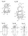
- a bearing block 4 shown in FIG. 2Ashows, according to FIG. 2B, that such bodies can be put together from simple basic bodies 4a to 4i, namely by quantity operations (so-called Boolean operations). This is also explained in the aforementioned DE-36 08 438-A1 on the prior art in CAD systems.
- FIGS. 3A to 3DThe generation of base bodies is shown by FIGS. 3A to 3D.
- FIG. 3Ashows a 2d contour in the form of a rectangle 5a.
- This rectangle 5ais shifted in the direction of a vector V by a certain amount.
- Rotation bodiescan be created in the same way by rotating a two-dimensional contour around an axis.
- a graphic representationhas been dispensed with, since it is easy to imagine that a circular ring with a rectangular cross-section arises when the rectangle 5a rotates about an axis outside of its contour.
- the hub 4bcould be defined by a rotating body which is generated by a rotating rectangle. Then the difference quantity formation of the round columns 4b ( ⁇ ) 4a according to FIG. 2B and the associated description would be omitted.
- a toolIn order to produce a body (rectangular column 5b or any other base body or combinations thereof) from a workpiece blank 2, a tool (ball mill 3) must be moved on an equidistant path to the desired contour.
- a milling path correctionis already carried out on the simple 2d contour 5a according to FIG. 3C.
- This tool path contouris shown in dash-dot lines and forms a corrected 2d contour with the designation 5c.
- the corrected 2d contouris translationally shifted along a vector V and in this way the corrected 3d object 5d (FIG. 3D) is formed.
- the surfaces of the corrected body 5ddescribe equidistant surfaces to the surfaces of the base body 5b.
- composition of the desired body to the workpiece to be producedis now carried out on the basis of the already corrected body, so that the tool path contours coincide with the cutting lines of a composite - already corrected - whole body 8, which will be discussed later with reference to FIG. 5.
- a methodis suitable with which, depending on the actual curvature of the curve an interpolation with 3d straight line sections is generated. This ensures that only as many straight line segments are generated as are necessary to maintain the maximum error, which leads to a large reduction in the amount of data and thus to a saving of storage space.
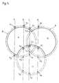
- Fig. 5the top view of a workpiece 8 and its corrected body 8 'is shown, which is formed from three basic bodies in the form of cylinders.
- the top viewrepresents a line of intersection between the surface of the workpiece 8 and the respective working plane.
- the cylindershave the designations 9, 10 and 11, 9 and 10 representing positive cylinders and 11 having to be subtracted as a negative cylinder in the composition of the workpiece 8.
- corrected cylinders for the elementary cylinders 9, 10 and 11are produced and linked in terms of quantity algebra in order to determine the corrected milling path data.
- the corrected basic bodyit is already determined whether the respective basic body is a positive body or a negative body.
- the valid boundary points for the milling pathare determined using a table below.
- auxiliary linesare placed over the corrected body 8 'shown in a certain grid.
- the sequence of the valid edge pointscorresponds to the milling path that generates the contour of the workpiece 8.
- the auxiliary line aintersects at point a1 with the cylinder 9 (or with its corrected contour).
- a1is the edge point (R) of cylinder 9 and lies outside (A) of cylinder 10, so a1 is a valid edge point for the union (9 ⁇ 10).
- a1is the boundary point (R) of the union (9 ⁇ 10) and lies outside (A) of cylinder 11; a1 is therefore also a valid boundary point for the difference set (9 ⁇ 10) ⁇ 11.
- intersection points a1 and a2are accordingly valid boundary points that the milling cutter may approach.
- Valid marginal pointsare in the tables and in Figure 5 marked with a concentric circle around the respective point, which should symbolize the ball end mill 3.
- auxiliary line bFor the auxiliary line b, only the edge points b1 and b2 are valid router path points.
- the edge points c1 and c3are valid router path points.
- auxiliary linesconsidered here is arbitrary. In the implementation of the invention, the auxiliary lines are so close together that there is a continuous milling path during milling.
- FIG. 6BA section of the contour K from FIG. 6A is shown there.
- the contour Kis generated with straight sections, of which only the section Ki is shown here.
- a milling cutter(not shown) would connect the points P1 and P2 of the contour K on this section Ki through its milling track.
- the perpendicularis dropped from the straight section Ki onto the contour K and the location of the greatest deviation is determined.
- the intersection of the contour K with the plumb linedetermines a point P3.
- the NC controlwith the aid of which point P3 was determined, defines the straight lines Kj and Kk as new straight line sections, with which the points P1 and P3 as well as P3 and P2 are connected. It can be seen that the so-called linearization by the new straight lines Kj and Kk has brought the contour K much better. If the same procedure is also carried out on the new straight line section Kk, the straight line sections K1 and Km generated thereby approach the real contour profile K very closely. It can be seen that with this method for curvature-dependent linearization, the length of the straight section also becomes curvature-dependent. With this process, the path of the milling cutter is matched to the ideal contour to the highest degree.
- FIG. 7shows in a simplified manner how the method is carried out.
- the machining parametersare set and checked in an apparatus 13 by an input unit 12. This can include the blank dimensions, the machining plane and the machining conditions be.
- the device 13is connected to a shape memory 14 which contains the complete body definitions.
- the bodiesare reduced to the basic bodies and the correction thereof is calculated from the parameters defined in the device 13.
- the data of the corrected contoursare stored in the 2d contour memory 16.
- the intersection lines of the base bodies with the processing planeare calculated using data from the shape memory 14 and the 2d contour memory 16.
- the cut contours of the bodiesare then stored in a further contour memory 18.
- the set operationsBoolean operations
- the calculated dataare passed on to the NC machine as tool path data.
Landscapes
- Engineering & Computer Science (AREA)
- Manufacturing & Machinery (AREA)
- Human Computer Interaction (AREA)
- Physics & Mathematics (AREA)
- General Physics & Mathematics (AREA)
- Automation & Control Theory (AREA)
- Computing Systems (AREA)
- Theoretical Computer Science (AREA)
- Numerical Control (AREA)
Description
Translated fromGermanDie Erfindung betrifft ein Verfahren für die Bearbeitung von Werkstücken gemäß dem Oberbegriff des Anspruchs 1.The invention relates to a method for machining workpieces according to the preamble of claim 1.
Derartige Verfahren sind aus zahlreichen Druckschriften bekannt. Beispielsweise ist aus der DE-36 08 438-A1, die der korrespondierenden US-4 868 761-A entspricht, ein sehr anspruchsvolles Verfahren bekannt, bei dem mittels computerunterstütztem Design (CAD) und computerunterstützter Herstellung (CAM) die Berechnung von freien gekrümmten Flächen für die Herstellung mittels numerisch gesteuerter Maschinen möglich sein soll.Such methods are known from numerous publications. For example, DE-36 08 438-A1, which corresponds to the corresponding US Pat. No. 4,868,761-A, discloses a very demanding method in which the calculation of free curved surfaces is performed using computer-aided design (CAD) and computer-aided manufacturing (CAM) should be possible for the production by means of numerically controlled machines.
Bei diesem Verfahren soll allerdings ausdrücklich die Funktion, eine Gestalt zu definieren, vollständig getrennt sein von der Funktion, den geometrischen Ort eines Werkzeugs zu bestimmen. Letzteres ist die Aufgabe einer numerischen Steuerung.In this method, however, the function of defining a shape is expressly to be completely separate from the function of determining the geometric location of a tool. The latter is the task of numerical control.
Diese vollständige Trennung ist aus dem Inhalt dieser Druckschrift und aus dem Wissen von Fachleuten verständlich, denn mit der Berechnung von mathematisch nur äußerst schwer bestimmbaren freien Flächen ist eine NC-Steuerung in der Praxis überfordert.This complete separation is understandable from the content of this document and from the knowledge of experts, because the calculation of free areas that are extremely difficult to determine mathematically is too much for an NC control in practice.
Der Erfindung liegt die Aufgabe zugrunde, ein Verfahren anzugeben, nach dem die Bearbeitung von mathematisch definierbaren Körpern auf einfache Weise möglich ist.The invention has for its object to provide a method by which the processing of mathematically definable bodies is possible in a simple manner.
Diese Aufgabe wird durch ein Verfahren mit den Merkmalen des Anspruches 1 gelöst.This object is achieved by a method having the features of claim 1.
Die Vorteile der Erfindung liegen darin, daß das allgemeine Problem der Herstellung beliebiger Körper auf die Gruppe von Körpern reduziert wird, die durch Grundkörper (sogenannte Primitive) konstruiert werden können, so daß die erforderlichen Fräserbahnen mit den Möglichkeiten einer NC-Steuerung berechnet und die Werkstücke auf NC-gesteuerten Maschinen hergestellt werden können.The advantages of the invention are that the general problem of producing any body is reduced to the group of bodies that can be constructed using basic bodies (so-called primitives), so that the necessary milling paths are calculated with the possibilities of an NC control and the workpieces can be manufactured on NC-controlled machines.
Die Erfindung wird nachstehend mit Hilfe der Zeichnungen anhand von Beispielen erläutert.The invention is explained below with the aid of the drawings using examples.
Es zeigt:
- Figur 1
- eine numerisch gesteuerte Fräsmaschine;
- Figur 2A
- einen Halter, der in
- Figur 2B
- in seine Grundkörper zerlegt dargestellt ist;
- Figur 3A
- eine 2d-Kontur und
- Figur 3B
- ein daraus erzeugtes 3d-Objekt,
- Figur 3C
- eine korrigierte 2d-Kontur und
- Figur 3D
- ein daraus erzeugtes korrigiertes 3d-Objekt;
- Figur 4A
- die Vereinigung zweier Grundkörper,
- Figur 4B
- die Differenz zweier Grundkörper und
Figur 4C- den Durchschnitt zweier Grundkörper;
Figur 5- ein Frästeil in Draufsicht;
- Figur 6A
- eine Fräserbahn-Kontur,
- Figur 6B
- einen vergrößerten Abschnitt der Fräserbahn-Kontur und
Figur 7- ein Blockdiagramm.
- Figure 1
- a numerically controlled milling machine;
- Figure 2A
- a holder that is in
- Figure 2B
- is shown broken down into its basic body;
- Figure 3A
- a 2d contour and
- Figure 3B
- a 3d object created from it,
- Figure 3C
- a corrected 2d contour and
- Figure 3D
- a corrected 3d object generated therefrom;
- Figure 4A
- the union of two basic bodies,
- Figure 4B
- the difference between two basic bodies and
- Figure 4C
- the average of two basic bodies;
- Figure 5
- a milled part in top view;
- Figure 6A
- a milling path contour,
- Figure 6B
- an enlarged section of the milling path contour and
- Figure 7
- a block diagram.
Eine in Figur 1 gezeigte numerisch gesteuerte Fräsmaschine 1 dient zur Durchführung des Verfahrens gemäß der Erfindung.A numerically controlled milling machine 1 shown in FIG. 1 is used to carry out the method according to the invention.
Ein zu bearbeitendes Werkstück wird durch einen Werkstück-Rohling 2 dargestellt und ein zur Bearbeitung des Werkstück-Rohlinges 2 dienendes Werkzeug wird durch einen Kugelfräser 3 realisiert.A workpiece to be machined is represented by a
Ein in Figur 2A dargestellter Lagerbock 4 zeigt gemäß Figur 2B, daß derartige Körper aus einfachen Grundkörpern 4a bis 4i zusammen gesetzt werden können, und zwar durch Mengenoperationen (sogenannte Bool'sche Operationen). Dies ist auch in der eingangs erwähnten DE-36 08 438-A1 zum Stand der Technik bei CAD-Systemen erläutert.A
Bezogen auf den Lagerbock 4 bedeutet dies, daß die Bohrung 4a (eine Rundsäule) von der Nabe 4b (auch eine Rundsäule) subtrahiert wird. Die Nabe 4b wird ihrerseits vom Steg 4d (eine Trapezsäule) abgezogen. Eine Trapezsäule 4d entsteht wiederum durch Subtraktion von zwei Dreiecksäulen 4c, 4e von dem ursprünglich eine Rechtecksäule darstellenden Steg 4d. Zu den vorgenannten einfachen Grundkörpern (auch Primitive genannt) wird eine Grundplatte 4f (eine Rechtecksäule) addiert. Eine weitere Rechtecksäule (Leiste 4g) wird ebenfalls addiert. Zwei von Rundsäulen gebildete Schraubenlöcher 4h und 4i werden subtrahiert. Aus diesem Beispiel wird ersichtlich, daß auch verhältnismäßig kompliziert erscheinende Körper wie der Lagerbock 4 aus einfachen, mathematisch bestimmbaren Grundkörpern 4a bis 4i zusammengesetzt werden kann.In relation to the
Die Erzeugung von Grundkörpern ist durch die Figuren 3A bis 3D dargestellt.The generation of base bodies is shown by FIGS. 3A to 3D.
In Figur 3A ist eine 2d-Kontur in Form eines Rechteckes 5a gezeigt. Dieses Rechteck 5a wird in Richtung eines Vektors V um einen bestimmten Betrag verschoben. Dadurch entsteht ein Translationskörper, der gemäß Figur 3B eine Rechtecksäule mit der Bezeichnung 5b darstellt. Auf diese Weise entstehen die Grundkörper, die bereits in der Figur 2B näher erläutert wurden.FIG. 3A shows a 2d contour in the form of a
Rotationskörper lassen sich auf die gleiche Weise erzeugen, indem eine zweidimensionale Kontur um eine Achse rotiert. Auf eine zeichnerische Darstellung wurde verzichtet, da leicht vorstellbar ist, daß ein Kreisring mit rechteckigem Querschnitt entsteht, wenn das Rechteck 5a um eine Achse außerhalb seiner Kontur rotiert. Unter Bezug auf Figur 2A ließe sich auf diese Weise durch einen Rotationskörper, der durch ein rotierendes Rechteck erzeugt wird, die Nabe 4b definieren. Dann entfiele die Differenzmengenbildung der Rundsäulen 4b ( \ ) 4a gemäß Figur 2B und zugehöriger Beschreibung.Rotation bodies can be created in the same way by rotating a two-dimensional contour around an axis. A graphic representation has been dispensed with, since it is easy to imagine that a circular ring with a rectangular cross-section arises when the
Um einen Körper (Rechtecksäule 5b oder beliebige andere Grundkörper bzw. deren Kombinationen) aus einem Werkstück-Rohling 2 herzustellen, muß ein Werkzeug (Kugelfräser 3) auf einer äquidistanten Bahn zu der gewünschten Kontur bewegt werden.In order to produce a body (
Maßgeblich für die Steuerung des Werkzeuges sind also nicht direkt die gewünschten Abmessungen des Werkstückes, sondern die um den Radius des Kugelfräsers 3 korrigierten Werkzeug-Bewegungsbahn-Daten.Decisive for the control of the tool are therefore not the desired dimensions of the workpiece, but rather the tool movement path data corrected by the radius of the ball milling cutter 3.
Wenn beliebige Körper, wie gemäß Figur 2A gezeigt, aus einfachen Grundkörpern zusammengesetzt werden, wie in Figur 2B gezeigt, so werden die Korrekturberechnungen verhältnismäßig kompliziert, da sich die durch die korrigierten Bahndaten bestimmten Werkzeugbahn-Konturen zwangsläufig nicht mit den Schnittlinien der zusammengesetzten Grundkörper decken.If any bodies, as shown in FIG. 2A, are composed of simple base bodies, as shown in FIG. 2B, the correction calculations become relatively complicated, since the tool path contours determined by the corrected path data do not necessarily coincide with the cutting lines of the composite base bodies.
Um die Ermittlung der Werkzeugbahn-Konturen bzw. deren Bahndaten zu vereinfachen, wird gemäß Figur 3C bereits an der einfachen 2d-Kontur 5a eine Fräserbahnkorrektur vorgenommen. Diese Werkzeugbahn-Kontur ist strichpunktiert dargestellt und bildet eine korrigierte 2d-Kontur mit der Bezeichnung 5c. Analog zur Erzeugung eines 3d-Objektes nach Figur 3A/3B wird die korrigierte 2d-Kontur entlang eines Vektors V translatorisch verschoben und auf diese Weise das korrigierte 3d-Objekt 5d (Figur 3D) gebildet. Wie die Zeichnung 3D erkennen läßt, beschreiben die Oberflächen des korrigierten Körpers 5d äquidistante Flächen zu den Oberflächen des Grundkörpers 5b.In order to simplify the determination of the tool path contours or their path data, a milling path correction is already carried out on the
Die Zusammensetzung der gewünschten Körper zum herzustellenden Werkstück erfolgt nun anhand der bereits korrigierten Körper, so daß die Werkzeugbahn-Konturen sich mit den Schnittlinien eines zusammengesetzten - bereits korrigierten - Gesamtkörpers 8 decken, auf den später anhand von Figur 5 noch eingegangen wird.The composition of the desired body to the workpiece to be produced is now carried out on the basis of the already corrected body, so that the tool path contours coincide with the cutting lines of a composite - already corrected -
Nun werden die Schnittlinien zwischen den korrigierten Oberflächen und der jeweiligen Bearbeitungsebene berechnet. Dies sind bei Translationskörpern Geradenabschnitte und bei Rotationskörpern die Kurven von allgemeinen Kegel- bzw. Zylinderschnitten.Now the cutting lines between the corrected surfaces and the respective working plane are calculated. These are straight sections for translational bodies and the curves of general conical or cylindrical sections for rotating bodies.
Es ist sinnvoll, die Folge der erzeugten Kurven zu linearisieren und zwar unter Berücksichtigung der durch die Maschine vorgegebenen Auflösung.It makes sense to linearize the sequence of the curves generated, taking into account the resolution specified by the machine.
Dazu ist ein Verfahren geeignet, mit dem in Abhängigkeit von der tatsächlichen Krümmung der Kurve eine Interpolation mit 3d-Geradenabschnitten erzeugt wird. Dadurch ist gewährleistet, daß immer nur soviele Geradenabschnitte erzeugt werden, wie zur Einhaltung des maximalen Fehlers notwendig sind, was zu einer starken Reduktion der Datenmengen und somit zur Einsparung von Speicherplatz führt.For this purpose, a method is suitable with which, depending on the actual curvature of the curve an interpolation with 3d straight line sections is generated. This ensures that only as many straight line segments are generated as are necessary to maintain the maximum error, which leads to a large reduction in the amount of data and thus to a saving of storage space.
Die Folge der auf diese Art und Weise berechneten Geradenabschnitte ergibt die korrigierte Schnittkontur.The result of the straight line sections calculated in this way results in the corrected cutting contour.
Dieses Verfahren wird später noch anhand der Figuren 6A und 6B beschrieben.This method will be described later with reference to FIGS. 6A and 6B.
In den Figuren 4A bis 4C werden drei Bool'sche Grundoperationen anhand zweier ineinander verschachtelter Zylinder 6 und 7 erläutert. Für die Herstellung solcher resultierender Körper ist es wichtig, ob ein beliebiger Punkt auf der Umrandung zulässig ist, oder ob er unzulässig ist. Diese Überprüfung wird später an komplizierten resultierenden Körpern näher erläutert, hier nur die Grundbedingungen:
- a. Figur 4A zeigt die
Vereinigung der Zylinder 6 und 7, also die Summe (∪).
Wenn die Vereinigungsmenge vonden zwei Teilkörpern 6 und 7 gebildet werden soll, ergibt sich ein gültiger Randpunkt 6a dann, wenn der Punkt 6aRandpunkt von Zylinder 6 ist und außerhalbvon Zylinder 7 liegt, oderein Punkt 7a istRandpunkt von Zylinder 7 und liegt außerhalbvon Zylinder 6. Ungültig ist hingegen der Punkt 6u, denn er liegt zwar auf dem Rand von Zylinder 6 (ist also Randpunkt von 6), aber er liegt innerhalbvon Zylinder 7, was nach den vorstehenden Regeln unzulässig ist. - b. Figur 4B zeigt die
Differenz der Zylinder 6 und 7, also die Operation ( \ ).
Wenn die Differenzmenge vonden zwei Teilkörpern 6 und 7 gebildet werden soll, ergibt sich ein gültiger Randpunkt 6b dann, wenn der Punkt 6bRandpunkt von Zylinder 6 ist und außerhalbvon Zylinder 7 liegt, oderein Punkt 7b istRandpunkt von Zylinder 7 und liegt innerhalbvon Zylinder 6. Ungültig ist hingegen der Punkt 7u, denn er liegt zwar auf demRand von Zylinder 7, aberaußerhalb von Zylinder 6, was unzulässig ist.
Wenn statt der Differenz 6 ( \ ) 7 die Differenz 7 ( \ ) 6 gebildet werden soll, gilt in entsprechender Abwandlung das gleiche. - c.
Figur 4C zeigt denDurchschnitt der Zylinder 6 und 7, also die Operation (∩).
Wenn die Schnittmenge vonden zwei Teilkörpern 6 und 7 gebildet werden soll, ergibt sich ein gültiger Randpunkt 6c dann, wenn der Punkt 6CRandpunkt von Zylinder 6 ist und innerhalbvon Zylinder 7 liegt, oder ein Punkt 7C istRandpunkt von Zylinder 7 und liegt innerhalbvon Zylinder 6.Ein Punkt 6u ist ungültig, obwohl er auf demRand von Zylinder 6 liegt, aber er liegt außerhalbvon Zylinder 7.
Punkte, die in Schnittpunkten von Umrandungen liegen, sind immer gültige Punkte.
- a. Figure 4A shows the union of
cylinders
If the union is to be formed by the twopartial bodies cylinder 6 and lies outside ofcylinder 7, or apoint 7a is the edge point ofcylinder 7 and lies outside ofcylinder 6. On the other hand,point 6u is invalid because it lies on the edge of cylinder 6 (is the edge point of 6), but it is lies withincylinder 7, which is not permitted according to the above rules. - b. FIG. 4B shows the difference between
cylinders
If the difference set is to be formed by the twopartial bodies cylinder 6 and lies outside ofcylinder 7, or apoint 7b is the boundary point ofcylinder 7 and lies within ofcylinder 6. However, point 7u is invalid because it lies on the edge ofcylinder 7, but outside ofcylinder 6, which is not permitted.
If instead of the difference 6 (\) 7 the difference 7 (\) 6 is to be formed, the same applies in a corresponding modification. - c. Figure 4C shows the average of
cylinders
If the intersection of the twopartial bodies cylinder 6 and lies withincylinder 7, or a point 7C is the edge point ofcylinder 7 and lies within ofcylinder 6. Apoint 6u is invalid, although it lies on the edge ofcylinder 6, but it lies outside ofcylinder 7.
Points that are in the intersection of borders are always valid points.
In Fig. 5 ist die Draufsicht auf ein Werkstück 8 und seinen korrigierten Körper 8′ gezeigt, das aus drei Grundkörpern in Form von Zylindern gebildet ist. Die Draufsicht stellt eine Schnittlinie zwischen der Oberfläche des Werkstückes 8 und der jeweiligen Bearbeitungsebene dar. Die Zylinder tragen die Bezeichnungen 9, 10 und 11, wobei 9 und 10 positive Zylinder darstellen und 11 als negativer Zylinder bei der Zusammensetzung des Werkstückes 8 subtrahiert werden muß.In Fig. 5 the top view of a
Um ein solches Werkstück 8 herstellen zu können, werden gemäß Vorstehendem zu den Elementar-Zylindern 9, 10 und 11 korrigierte Zylinder erzeugt und mengenalgebraisch verknüpft, um die korrigierten Fräserbahn-Daten zu ermitteln. Bei der Erzeugung der korrigierten Grundkörper wird bereits festgestellt, ob der jeweilige Grundkörper ein Positiv-Körper oder ein Negativ-Körper ist. Mit mengenalgebraischen Operationen werden nachstehend anhand einer Tabelle die gültigen Randpunkte für die Fräserbahn ermittelt.In order to be able to produce such a
Um die gültigen Randpunkte zu ermitteln, werden über den dargestellten korrigierten Körper 8′ in einem bestimmten Raster Hilfslinien gelegt. Die Folge der gültigen Randpunkte entspricht der Fräserbahn, die die Kontur des Werkstückes 8 erzeugt.In order to determine the valid boundary points, auxiliary lines are placed over the corrected body 8 'shown in a certain grid. The sequence of the valid edge points corresponds to the milling path that generates the contour of the
Zur Verdeutlichung sind lediglich vier Hilfslinien a, b, c, d dargestellt, die aber das Prinzip verständlich machen.For clarification, only four auxiliary lines a, b, c, d are shown, but which make the principle understandable.
Die Grundbedingung der hier vorliegenden Mengenoperation lautet für die drei Zylinder: 9 und 10 bilden eine Vereinigungsmenge, von der die Menge 11 subtrahiert wird:
Die folgenden Randpunktbetrachtungen werden immer an den Konturen der korrigierten Körper 9, 10 und 11 durchgeführt und sind analog zu den Erläuterungen zu den Figuren 4A, 4B und 4C.The following considerations of the boundary points are always carried out on the contours of the corrected
Die Hilfslinie a schneidet sich am Punkt a1 mit dem Zylinder 9 (bzw. mit dessen korrigierter Kontur).The auxiliary line a intersects at point a1 with the cylinder 9 (or with its corrected contour).
a1 ist Randpunkt (R) von Zylinder 9 und liegt außerhalb (A) von Zylinder 10, also ist a1 bei der Vereinigungsmenge (9 ∪ 10) ein gültiger Randpunkt. Zur Vereinigungsmenge (9 ∪ 10) bildet 11 die Differenzmenge. Dafür gilt: a1 ist Randpunkt (R) von der Vereinigungsmenge (9 ∪ 10) und liegt außerhalb (A) von Zylinder 11; a1 ist also auch für die Differenzmenge (9 ∪ 10)\11 ein gültiger Randpunkt.a1 is the edge point (R) of
Tabellarisch ausgedrückt:


Beide Schnittpunkte a1 und a2 sind demgemäß gültige Randpunkte, die der Fräser anfahren darf. Gültige Randpunkte werden in den Tabellen und in Figur 5 mit einem konzentrischen Kreis um den jeweiligen Punkt kenntlich gemacht, der den Kugelfräser 3 symbolisieren soll.Both intersection points a1 and a2 are accordingly valid boundary points that the milling cutter may approach. Valid marginal points are in the tables and in Figure 5 marked with a concentric circle around the respective point, which should symbolize the ball end mill 3.
Für die Hilfslinie b ergibt sich analog:


Da Punkt b3 nicht für alle Bedingungen gültig ist, stellt er keinen gültigen Randpunkt für die Bearbeitung dar.

Bei der Hilfslinie b sind also nur die Randpunkte b1 und b2 gültige Fräserbahn-Punkte.
Für die Hilfslinie C gilt:


The following applies to the auxiliary line C:
Bei der Hilfslinie c sind demgemäß die Randpunkte c1 und c3 gültige Fräserbahn-Punkte.Accordingly, for the auxiliary line c, the edge points c1 and c3 are valid router path points.
Für die Hilfslinie d gilt die Betrachtung:


Bei der Betrachtung der stärker ausgezogenen Begrenzungslinie des Werkstückes 8 zeigt sich, daß alle als gültige Punkte erkannten Randpunkte a1, a2; b1, b2; c1, c3; d1, d2 auf der korrigierten Kontur, also auf einer Äquidistanten zur Werkstückkontur liegen, deren Abstand dem Radius r des Kugelfräsers 3 aus Figur 1 entspricht.Looking at the more solid boundary line of the
Die Lage der hier betrachteten Hilfslinien ist willkürlich. Bei der Realisierung der Erfindung liegen die Hilfslinien so eng beieinander, daß sich beim Fräsen eine kontinuierlich verlaufende Fräserbahn ergibt.The location of the auxiliary lines considered here is arbitrary. In the implementation of the invention, the auxiliary lines are so close together that there is a continuous milling path during milling.
Nunmehr soll die vorerwähnte Linearisierung anhand der Figuren 6A und 6B erläutert werden. In Figur 6A ist ein gekrümmter Verlauf einer Kontur K gezeigt, der gemäß dem Stand der Technik durch Geradenabschnitte (ki (i = 1 ... n)) eines fest vorgegebenen Rasters angenähert von der Fräsmaschine erzeugt wird. Da die Weite der Geradenabschnitte festliegt, nimmt die Abweichung der tatsächlich erzeugten Kontur von der gewünschten bzw. idealen Kontur K mit zunehmender Krümmung dieser Kontur K zu.The aforementioned linearization will now be explained with reference to FIGS. 6A and 6B. FIG. 6A shows a curved course of a contour K which, according to the prior art, is generated approximately by the milling machine by straight line sections (ki (i = 1 ... n)) of a predetermined grid. Since the width of the straight line sections is fixed, the deviation of the actually generated contour from the desired or ideal contour K increases with increasing curvature of this contour K.
Besonders deutlich wird dies durch die übertriebene Darstellung in Figur 6B. Dort ist ein Ausschnitt der Kontur K aus Figur 6A gezeigt.This is particularly clear from the exaggerated representation in FIG. 6B. A section of the contour K from FIG. 6A is shown there.
Die Kontur K wird mit Geradenabschnitten erzeugt, von denen hier nur der Abschnitt Ki dargestellt ist. Ein nicht dargestellter Fräser würde auf diesem Abschnitt Ki die Punkte P1 und P2 der Kontur K durch seine Fräserbahn verbinden.The contour K is generated with straight sections, of which only the section Ki is shown here. A milling cutter (not shown) would connect the points P1 and P2 of the contour K on this section Ki through its milling track.
Um die Annäherung an die gewünschte Kontur K zu verbessern, wird das Lot von dem Geradenabschnitt Ki auf die Kontur K gefällt und der Ort der größten Abweichung festgestellt. Der Schnittpunkt der Kontur K mit dem Lot bestimmt einen Punkt P3. Die NC-Steuerung, mit deren Hilfe der Punkt P3 ermittelt wurde, legt als neue Geradenabschnitte die Geraden Kj und Kk fest, mit denen die Punkte P1 und P3 sowie P3 und P2 verbunden werden. Es zeigt sich, daß die sogenannte Linearisierung durch die neuen Geraden Kj und Kk schon deutlich bessere Annäherung an die Kontur K gebracht hat. Wenn die gleiche Verfahrensweise auch an dem neuen Geradenabschnitt Kk durchgeführt wird, nähern sich die dadurch erzeugten Geradenabschnitte Kl und Km schon sehr stark an den realen Konturenverlauf K an. Es ist ersichtlich, daß mit diesem Verfahren zur krümmungsabhängigen Linearisierung auch die Geradenabschnittslänge krümmungsabhängig wird. Mit diesem Verfahren wird die Bahn des Fräsers an die Idealkontur in höchstem Maße angeglichen.In order to improve the approximation to the desired contour K, the perpendicular is dropped from the straight section Ki onto the contour K and the location of the greatest deviation is determined. The intersection of the contour K with the plumb line determines a point P3. The NC control, with the aid of which point P3 was determined, defines the straight lines Kj and Kk as new straight line sections, with which the points P1 and P3 as well as P3 and P2 are connected. It can be seen that the so-called linearization by the new straight lines Kj and Kk has brought the contour K much better. If the same procedure is also carried out on the new straight line section Kk, the straight line sections K1 and Km generated thereby approach the real contour profile K very closely. It can be seen that with this method for curvature-dependent linearization, the length of the straight section also becomes curvature-dependent. With this process, the path of the milling cutter is matched to the ideal contour to the highest degree.
Im in Figur 7 gezeigten Blockdiagramm ist vereinfacht dargestellt, wie der Ablauf des Verfahrens erfolgt.The block diagram shown in FIG. 7 shows in a simplified manner how the method is carried out.
Durch eine Eingabeeinheit 12 werden in einer Vorrichtung 13 die Bearbeitungsparameter festgelegt und überprüft. Dies können die Rohlingabmessungen, die Bearbeitungsebene und die Zerspanungsbedingungen sein. Die Vorrichtung 13 ist mit einem Formenspeicher 14 verbunden, der die kompletten Körperdefinitionen enthält.The machining parameters are set and checked in an
Aus den in der Vorrichtung 13 festgelegten Parametern werden in einem weiteren Schritt im Bauteil 15 die Körper auf die Grundkörper reduziert und deren Korrektur berechnet. Die Daten der korrigierten Konturen werden im 2d-Konturenspeicher 16 abgelegt.In a further step in the
Im Rechner 17 werden mit Daten aus dem Formenspeicher 14 und dem 2d-Konturenspeicher 16 die Schnittlinien der Grundkörper mit der Bearbeitungsebene berechnet. Danach werden in einem weiteren Konturenspeicher 18 die Schnittkonturen der Körper abgespeichert. Anschließend werden mit Hilfe des Rechners 19 mit den erzeugten Schnittlinien die Mengenoperationen (Bool'sche Operationen) durchgeführt und die errechneten Daten als Werkzeugbahn-Daten an die NC-Maschine weitergegeben.In the
Claims (7)
- A method of machining workpieces by combining workpiece blank data with tool path data with the aid of a numerical control, in which the workpiece contour is formed by combinations of mathematically defined basic bodies, characterized by the following method steps:a) tool radius corrections are applied to data for two-dimensional contours (2d-contours) (5a), which are stored as corrected 2d-contours (5c);b) corrected three-dimensional basic bodies (3d-objects) (5d, 9, 10, 11) are created from the data for corrected two-dimensional contours (2d-contours) (5C) by translating and/or rotating these contours and the data for these bodies are stored;c) the data for the corrected three-dimensional basic bodies (3d-objects) (5d, 9, 10, 11) are combined to data for assembled bodies (8′) arbitrarily orientated in space and are stored, the surfaces of these corrected bodies (8′) describing the surfaces of an equidistant workpiece (8).
- A method according to claim 1, characterized in that solid bodies, hollow bodies or negative bodies are created as corrected basic bodies (5d, 9, 10, 11).
- A method according to claim 1, characterized in that bodies (8′) arbitrarily orientated in space are created by transformations of the data of the corrected assembled bodies (8′).
- A method according to claim 1, characterized in that curved contours of cutting lines which result between the surfaces of the corrected bodies (8′) and the respective machining planes determined by the tool path data are linearised section by section by interpolation.
- A method according to claim 4, characterized in that the linearisation sections are dependent on the strength of the curvature.
- A method according to claim 4, characterized in that the number of interpolation sections is limited by a permitted deviation of the linearised contour from the curved contour (K).
- A method according to claim 1, characterized in that row-wise and/or column-wise cutting point tests are carried out on the basis of the data of the corrected assembled bodies (8′) with the aid of Boolean operations, in order to obtain permissible boundary points (a1, a2; b1, b2; c1, c3; d1, d2) for the machining path.
Priority Applications (6)
| Application Number | Priority Date | Filing Date | Title |
|---|---|---|---|
| ES90118385TES2068302T3 (en) | 1990-09-25 | 1990-09-25 | PROCEDURE FOR MACHINING PARTS WITH A NUMERICAL CONTROL MACHINE. |
| DE59008038TDE59008038D1 (en) | 1990-09-25 | 1990-09-25 | Process for machining workpieces with numerically controlled machines. |
| EP90118385AEP0477398B1 (en) | 1990-09-25 | 1990-09-25 | Method to machine workpieces with a numerical controlled machine |
| DE4038073ADE4038073A1 (en) | 1990-09-25 | 1990-11-29 | METHOD FOR MACHINING WORKPIECES WITH NUMERICALLY CONTROLLED MACHINES |
| JP3243710AJP2865911B2 (en) | 1990-09-25 | 1991-09-24 | How to process a workpiece with a numerically controlled machine |
| US07/765,562US5295075A (en) | 1990-09-25 | 1991-09-25 | Method and apparatus for machining workpieces with numerically controlled machines |
Applications Claiming Priority (1)
| Application Number | Priority Date | Filing Date | Title |
|---|---|---|---|
| EP90118385AEP0477398B1 (en) | 1990-09-25 | 1990-09-25 | Method to machine workpieces with a numerical controlled machine |
Publications (3)
| Publication Number | Publication Date |
|---|---|
| EP0477398A2 EP0477398A2 (en) | 1992-04-01 |
| EP0477398A3 EP0477398A3 (en) | 1992-04-29 |
| EP0477398B1true EP0477398B1 (en) | 1994-12-14 |
Family
ID=8204511
Family Applications (1)
| Application Number | Title | Priority Date | Filing Date |
|---|---|---|---|
| EP90118385AExpired - LifetimeEP0477398B1 (en) | 1990-09-25 | 1990-09-25 | Method to machine workpieces with a numerical controlled machine |
Country Status (5)
| Country | Link |
|---|---|
| US (1) | US5295075A (en) |
| EP (1) | EP0477398B1 (en) |
| JP (1) | JP2865911B2 (en) |
| DE (2) | DE59008038D1 (en) |
| ES (1) | ES2068302T3 (en) |
Families Citing this family (14)
| Publication number | Priority date | Publication date | Assignee | Title |
|---|---|---|---|---|
| ES2080774T3 (en)* | 1990-09-25 | 1996-02-16 | Heidenhain Gmbh Dr Johannes | PROCEDURE TO DETERMINE THE PATH CONTOUR OF THE UTIL FOR NUMERICAL CONTROL MACHINES. |
| FR2693567B1 (en)* | 1992-07-10 | 1994-10-14 | Caso | Method and device for manufacturing adhesive elements intended to be applied to a three-dimensional surface for decoration. |
| JPH1049212A (en)* | 1996-04-10 | 1998-02-20 | Ind Elektronik Agie Losone Locarno:Ag | Method and device for controlling machine tool |
| GB2327289B (en)* | 1997-07-15 | 1999-09-15 | Honda Motor Co Ltd | Job aiding apparatus |
| DE10144710A1 (en)* | 2001-09-11 | 2003-03-27 | Heidenhain Gmbh Dr Johannes | Machining contoured or shaped recesses defined by CSG with digitally controlled machine tools, with a user interface that can be used by unskilled or inexperienced operators |
| US7031790B2 (en)* | 2002-09-23 | 2006-04-18 | Autodesk, Inc. | Operator for sculpting solids with sheet bodies |
| JP2007511008A (en)* | 2003-11-04 | 2007-04-26 | コンスタント・データ、インコーポレイテッド | Hybrid real-time data replication |
| US7870354B2 (en)* | 2003-11-04 | 2011-01-11 | Bakbone Software, Inc. | Data replication from one-to-one or one-to-many heterogeneous devices |
| US20060268549A1 (en)* | 2005-05-09 | 2006-11-30 | Shawn Oehlke | Omnidirectional light |
| CN100402231C (en)* | 2006-07-31 | 2008-07-16 | 毛国良 | A Control Method of CNC Bearing Ring Automatic Lathe Tool |
| US20100179689A1 (en)* | 2009-01-09 | 2010-07-15 | National Taiwan University Of Science And Technology | Method of teaching robotic system |
| CN104126157B (en)* | 2013-02-21 | 2016-01-20 | 三菱电机株式会社 | Interference checking device and numerical control device |
| CN107220213A (en)* | 2017-06-13 | 2017-09-29 | 广州启煌科技有限公司 | Five-axle number control machine tool on-line measurement analysis method |
| CN115441364B (en)* | 2022-08-16 | 2024-03-05 | 国网江苏省电力有限公司无锡供电分公司 | Light-weight high-precision cutting mechanism for cable insulation stripping and cutting intelligent robot |
Family Cites Families (34)
| Publication number | Priority date | Publication date | Assignee | Title |
|---|---|---|---|---|
| US3629558A (en)* | 1969-09-12 | 1971-12-21 | Bendix Corp | Method for preparing control tapes |
| US3757095A (en)* | 1970-08-26 | 1973-09-04 | Tektronix Inc | Numerical control system |
| US3927948A (en)* | 1972-06-15 | 1975-12-23 | Leonard C Cox | Apparatus for producing data indicative of the geometric shape and arrangement of the various components of a model |
| US4031369A (en)* | 1975-08-12 | 1977-06-21 | The Bendix Corporation | Interpolation and control apparatus and method for a numerical control system |
| US4127849A (en)* | 1975-11-03 | 1978-11-28 | Okor Joseph K | System for converting coded data into display data |
| US4162527A (en)* | 1977-07-29 | 1979-07-24 | Hamill Company, Inc. | Numerically controlled machine tool system with programmable tool offset |
| US4275449A (en)* | 1978-04-28 | 1981-06-23 | National Research Development Corporation | Modelling arrangements |
| DE3113970A1 (en)* | 1981-04-07 | 1982-11-04 | Dr. Johannes Heidenhain Gmbh, 8225 Traunreut | NUMERICAL PATTERN CONTROL FOR A MACHINE TOOL |
| US4550383A (en)* | 1981-09-24 | 1985-10-29 | Hitachi, Ltd. | Parabolic position and attitude interpolation for a robot hand |
| JPS5882310A (en)* | 1981-11-12 | 1983-05-17 | Fanuc Ltd | Numerical controlling with position display function |
| EP0088503A3 (en)* | 1982-02-17 | 1986-02-26 | Imperial Chemical Industries Plc | Photogrammetric computer aided method for plant construction |
| US4536848A (en)* | 1982-04-15 | 1985-08-20 | Polaroid Corporation | Method and apparatus for colored computer graphic photography |
| US4551810B1 (en)* | 1982-07-28 | 1995-09-05 | Technology Inc Const | Method and apparatus for designing duct work for producing patterns for conduit sections in the designated duct work |
| JPS59140513A (en)* | 1983-01-31 | 1984-08-11 | Fanuc Ltd | Color graphic display device for nc |
| JPS59158409A (en)* | 1983-03-01 | 1984-09-07 | Mitsubishi Electric Corp | Numerical controller |
| DE3311119C2 (en)* | 1983-03-26 | 1986-12-04 | Dr. Johannes Heidenhain Gmbh, 8225 Traunreut | Method for returning a tool to a workpiece contour |
| GB2140937A (en)* | 1983-05-10 | 1984-12-05 | Philips Nv | Simulation of machine tools |
| DE3338765C2 (en)* | 1983-10-26 | 1986-01-30 | Dr. Johannes Heidenhain Gmbh, 8225 Traunreut | Circuit arrangement for the representation of changeable structures |
| JPS60107106A (en)* | 1983-11-15 | 1985-06-12 | Mitsubishi Electric Corp | curve interpolator |
| JPS60127952A (en)* | 1983-12-14 | 1985-07-08 | Fanuc Ltd | Regional work |
| US4552710A (en)* | 1984-01-03 | 1985-11-12 | International Business Machines Corporation | Process of hot isostatic pressing of ferrite material |
| DE3401060A1 (en)* | 1984-01-13 | 1986-01-23 | Dr. Johannes Heidenhain Gmbh, 8225 Traunreut | METHOD FOR PRESENTING AN IMAGE |
| DE3403677A1 (en)* | 1984-02-03 | 1985-08-08 | Dr. Johannes Heidenhain Gmbh, 8225 Traunreut | METHOD FOR PRODUCING WORKPIECE CONTOURS |
| US4704688A (en)* | 1984-06-12 | 1987-11-03 | Mitsubishi Denki Kabushiki Kaisha | Interpolation method for numerical control machine |
| US4618924A (en)* | 1984-09-28 | 1986-10-21 | General Electric Company | Automatic machining using constructive solid geometry with Boolean combinations of primitives including tool offsets to form a machining pattern |
| GB2169853B (en)* | 1985-01-19 | 1988-11-02 | Francotyp Postalia Gmbh | Improvements in movement monitoring devices |
| DE3608438A1 (en)* | 1985-03-13 | 1986-09-18 | Toshiba Kikai K.K., Tokio/Tokyo | METHOD FOR CALCULATING FREE CURVED SURFACES BY MEANS OF COMPUTER-AID DESIGN CAD AND COMPUTER-AID MANUFACTURING CAM AND NUMERICAL CONTROL NC |
| JPH061406B2 (en)* | 1985-09-05 | 1994-01-05 | 松下電器産業株式会社 | Method of teaching a moving body route |
| JPH061404B2 (en)* | 1985-09-13 | 1994-01-05 | フアナツク株式会社 | Complex curved surface processing method |
| DE3616740A1 (en)* | 1986-05-17 | 1987-11-19 | Heidenhain Gmbh Dr Johannes | DEVICE FOR OBTAINING WORKPIECE CONTOURS |
| JPH0766290B2 (en)* | 1986-06-26 | 1995-07-19 | 東芝機械株式会社 | Tool path generation method |
| US4833617A (en)* | 1987-08-14 | 1989-05-23 | General Electric Company | Solid modeling based adaptive feedrate control for NC machining |
| ATE102371T1 (en)* | 1988-12-06 | 1994-03-15 | Heidenhain Gmbh Dr Johannes | METHOD FOR SIMULATING THE MACHINING OF A WORKPIECE AND REPRESENTING THE SAME, AND DEVICE FOR IMPLEMENTING THE METHOD. |
| JP2619532B2 (en)* | 1989-06-28 | 1997-06-11 | ファナック株式会社 | Involute interpolation error correction method |
- 1990
- 1990-09-25EPEP90118385Apatent/EP0477398B1/ennot_activeExpired - Lifetime
- 1990-09-25ESES90118385Tpatent/ES2068302T3/ennot_activeExpired - Lifetime
- 1990-09-25DEDE59008038Tpatent/DE59008038D1/ennot_activeExpired - Fee Related
- 1990-11-29DEDE4038073Apatent/DE4038073A1/ennot_activeWithdrawn
- 1991
- 1991-09-24JPJP3243710Apatent/JP2865911B2/ennot_activeExpired - Lifetime
- 1991-09-25USUS07/765,562patent/US5295075A/ennot_activeExpired - Fee Related
Also Published As
| Publication number | Publication date |
|---|---|
| US5295075A (en) | 1994-03-15 |
| JPH04230504A (en) | 1992-08-19 |
| DE4038073A1 (en) | 1992-03-26 |
| ES2068302T3 (en) | 1995-04-16 |
| EP0477398A2 (en) | 1992-04-01 |
| JP2865911B2 (en) | 1999-03-08 |
| DE59008038D1 (en) | 1995-01-26 |
| EP0477398A3 (en) | 1992-04-29 |
Similar Documents
| Publication | Publication Date | Title |
|---|---|---|
| EP0477398B1 (en) | Method to machine workpieces with a numerical controlled machine | |
| DE3616740C2 (en) | ||
| EP0153556B1 (en) | Method for graphical presentation of drawings | |
| EP1981674B1 (en) | Method for machining bevel gears in a pitching method with complete pitch error compensation | |
| DE102018108632A1 (en) | Device for chamfering a workpiece | |
| DE102010036499A1 (en) | Tool vector display device for a machine tool with a rotation axis | |
| DE3403677C2 (en) | ||
| EP0477397B2 (en) | Method to determine the contour of the machine tool path by a numerically controlled machine | |
| DE3403678A1 (en) | METHOD FOR REPRESENTING OBJECTS | |
| EP0477396B1 (en) | Method to determine the contour of the machine tool path by a numerically controlled machine | |
| EP1040396B1 (en) | Method for processing work pieces by removing material | |
| DE3820566C2 (en) | Method for determining a path of movement of a machining tool of a machine tool controlled by a numerical control device | |
| WO2022152457A1 (en) | Method for producing a device for moving a workpiece from a first tool into a second tool, electronic computing unit, computer program product and computer-readable medium | |
| DE3700887C2 (en) | ||
| DE3810662C2 (en) | ||
| EP3644151B1 (en) | Method for 3d radius correction in cnc milling and milling machine for same | |
| DE69213955T2 (en) | REAL-TIME TOOL WORKING SYSTEM, ESPECIALLY FOR A GRINDING SYSTEM | |
| EP0563412A1 (en) | Numerical control of machine-tools with interrupt and restart of machining process | |
| DE102017219512B4 (en) | Process for producing a leg or foot prosthesis by machining | |
| DE112022005403T5 (en) | Information processing device, machine tool control device, and computer program | |
| WO2023241846A1 (en) | Compensation of tool deflection by dynamically adjusting the tool geometry | |
| EP4621507A1 (en) | Operating a machine for processing a workpiece | |
| EP3499328A1 (en) | Efficient high-precision modelling of the removal of material | |
| EP1428180A1 (en) | Method and device for machining contoured recesses defined by csg | |
| EP3454149A1 (en) | Optimised allocation of process signals to contours of a workpiece |
Legal Events
| Date | Code | Title | Description |
|---|---|---|---|
| PUAI | Public reference made under article 153(3) epc to a published international application that has entered the european phase | Free format text:ORIGINAL CODE: 0009012 | |
| PUAL | Search report despatched | Free format text:ORIGINAL CODE: 0009013 | |
| 17P | Request for examination filed | Effective date:19901015 | |
| AK | Designated contracting states | Kind code of ref document:A2 Designated state(s):AT CH DE ES FR GB IT LI NL SE | |
| AK | Designated contracting states | Kind code of ref document:A3 Designated state(s):AT CH DE ES FR GB IT LI NL SE | |
| 17Q | First examination report despatched | Effective date:19940406 | |
| RBV | Designated contracting states (corrected) | Designated state(s):CH DE ES FR GB IT LI | |
| ITF | It: translation for a ep patent filed | ||
| GRAA | (expected) grant | Free format text:ORIGINAL CODE: 0009210 | |
| AK | Designated contracting states | Kind code of ref document:B1 Designated state(s):CH DE ES FR GB IT LI | |
| ET | Fr: translation filed | ||
| REF | Corresponds to: | Ref document number:59008038 Country of ref document:DE Date of ref document:19950126 | |
| GBT | Gb: translation of ep patent filed (gb section 77(6)(a)/1977) | Effective date:19950109 | |
| REG | Reference to a national code | Ref country code:ES Ref legal event code:FG2A Ref document number:2068302 Country of ref document:ES Kind code of ref document:T3 | |
| PLBE | No opposition filed within time limit | Free format text:ORIGINAL CODE: 0009261 | |
| STAA | Information on the status of an ep patent application or granted ep patent | Free format text:STATUS: NO OPPOSITION FILED WITHIN TIME LIMIT | |
| 26N | No opposition filed | ||
| PGFP | Annual fee paid to national office [announced via postgrant information from national office to epo] | Ref country code:GB Payment date:20000814 Year of fee payment:11 | |
| PGFP | Annual fee paid to national office [announced via postgrant information from national office to epo] | Ref country code:CH Payment date:20000816 Year of fee payment:11 | |
| PGFP | Annual fee paid to national office [announced via postgrant information from national office to epo] | Ref country code:FR Payment date:20000831 Year of fee payment:11 | |
| PGFP | Annual fee paid to national office [announced via postgrant information from national office to epo] | Ref country code:ES Payment date:20000922 Year of fee payment:11 | |
| PG25 | Lapsed in a contracting state [announced via postgrant information from national office to epo] | Ref country code:GB Free format text:LAPSE BECAUSE OF NON-PAYMENT OF DUE FEES Effective date:20010925 | |
| PG25 | Lapsed in a contracting state [announced via postgrant information from national office to epo] | Ref country code:ES Free format text:LAPSE BECAUSE OF NON-PAYMENT OF DUE FEES Effective date:20010926 | |
| PG25 | Lapsed in a contracting state [announced via postgrant information from national office to epo] | Ref country code:LI Free format text:LAPSE BECAUSE OF NON-PAYMENT OF DUE FEES Effective date:20010930 Ref country code:CH Free format text:LAPSE BECAUSE OF NON-PAYMENT OF DUE FEES Effective date:20010930 | |
| REG | Reference to a national code | Ref country code:GB Ref legal event code:IF02 | |
| GBPC | Gb: european patent ceased through non-payment of renewal fee | Effective date:20010925 | |
| REG | Reference to a national code | Ref country code:CH Ref legal event code:PL | |
| PG25 | Lapsed in a contracting state [announced via postgrant information from national office to epo] | Ref country code:FR Free format text:LAPSE BECAUSE OF NON-PAYMENT OF DUE FEES Effective date:20020531 | |
| REG | Reference to a national code | Ref country code:FR Ref legal event code:ST | |
| REG | Reference to a national code | Ref country code:ES Ref legal event code:FD2A Effective date:20021011 | |
| PG25 | Lapsed in a contracting state [announced via postgrant information from national office to epo] | Ref country code:IT Free format text:LAPSE BECAUSE OF NON-PAYMENT OF DUE FEES Effective date:20050925 | |
| PGFP | Annual fee paid to national office [announced via postgrant information from national office to epo] | Ref country code:DE Payment date:20060926 Year of fee payment:17 | |
| PG25 | Lapsed in a contracting state [announced via postgrant information from national office to epo] | Ref country code:DE Free format text:LAPSE BECAUSE OF NON-PAYMENT OF DUE FEES Effective date:20080401 |