EP0474615B1 - D.C. offset compensation in a radio receiver - Google Patents
D.C. offset compensation in a radio receiverDownload PDFInfo
- Publication number
- EP0474615B1 EP0474615B1EP91850216AEP91850216AEP0474615B1EP 0474615 B1EP0474615 B1EP 0474615B1EP 91850216 AEP91850216 AEP 91850216AEP 91850216 AEP91850216 AEP 91850216AEP 0474615 B1EP0474615 B1EP 0474615B1
- Authority
- EP
- European Patent Office
- Prior art keywords
- signal
- digital
- integrating
- received
- signals
- Prior art date
- Legal status (The legal status is an assumption and is not a legal conclusion. Google has not performed a legal analysis and makes no representation as to the accuracy of the status listed.)
- Expired - Lifetime
Links
- 238000000034methodMethods0.000claimsdescription34
- 230000003044adaptive effectEffects0.000claimsdescription19
- 230000000903blocking effectEffects0.000claimsdescription15
- 239000003990capacitorSubstances0.000claimsdescription11
- 230000007423decreaseEffects0.000claimsdescription2
- 230000003247decreasing effectEffects0.000claimsdescription2
- 230000006978adaptationEffects0.000claims1
- 230000010354integrationEffects0.000description28
- 230000006870functionEffects0.000description11
- 230000004069differentiationEffects0.000description9
- 230000003321amplificationEffects0.000description8
- 238000003199nucleic acid amplification methodMethods0.000description8
- 230000008901benefitEffects0.000description5
- 230000005540biological transmissionEffects0.000description5
- 230000008859changeEffects0.000description5
- 238000010586diagramMethods0.000description5
- 230000008569processEffects0.000description5
- 239000013598vectorSubstances0.000description5
- 108010076504Protein Sorting SignalsProteins0.000description4
- 230000000875corresponding effectEffects0.000description4
- 239000011159matrix materialSubstances0.000description4
- 238000006243chemical reactionMethods0.000description3
- 230000002028prematureEffects0.000description3
- 230000001427coherent effectEffects0.000description2
- 239000013256coordination polymerSubstances0.000description2
- 230000009977dual effectEffects0.000description2
- 230000010363phase shiftEffects0.000description2
- 238000009825accumulationMethods0.000description1
- 230000003213activating effectEffects0.000description1
- 230000001413cellular effectEffects0.000description1
- 230000002596correlated effectEffects0.000description1
- 230000008878couplingEffects0.000description1
- 238000010168coupling processMethods0.000description1
- 238000005859coupling reactionMethods0.000description1
- 230000003111delayed effectEffects0.000description1
- 230000000694effectsEffects0.000description1
- 238000001914filtrationMethods0.000description1
- 238000012886linear functionMethods0.000description1
- 230000035484reaction timeEffects0.000description1
- 230000002441reversible effectEffects0.000description1
Images


Classifications
- H—ELECTRICITY
- H04—ELECTRIC COMMUNICATION TECHNIQUE
- H04L—TRANSMISSION OF DIGITAL INFORMATION, e.g. TELEGRAPHIC COMMUNICATION
- H04L25/00—Baseband systems
- H04L25/02—Details ; arrangements for supplying electrical power along data transmission lines
- H04L25/06—DC level restoring means; Bias distortion correction ; Decision circuits providing symbol by symbol detection
- H04L25/061—DC level restoring means; Bias distortion correction ; Decision circuits providing symbol by symbol detection providing hard decisions only; arrangements for tracking or suppressing unwanted low frequency components, e.g. removal of DC offset
- H04L25/062—Setting decision thresholds using feedforward techniques only
- H—ELECTRICITY
- H03—ELECTRONIC CIRCUITRY
- H03D—DEMODULATION OR TRANSFERENCE OF MODULATION FROM ONE CARRIER TO ANOTHER
- H03D3/00—Demodulation of angle-, frequency- or phase- modulated oscillations
- H03D3/007—Demodulation of angle-, frequency- or phase- modulated oscillations by converting the oscillations into two quadrature related signals
- H03D3/008—Compensating DC offsets
- H—ELECTRICITY
- H04—ELECTRIC COMMUNICATION TECHNIQUE
- H04B—TRANSMISSION
- H04B1/00—Details of transmission systems, not covered by a single one of groups H04B3/00 - H04B13/00; Details of transmission systems not characterised by the medium used for transmission
- H04B1/06—Receivers
- H04B1/16—Circuits
- H04B1/30—Circuits for homodyne or synchrodyne receivers
- H—ELECTRICITY
- H03—ELECTRONIC CIRCUITRY
- H03D—DEMODULATION OR TRANSFERENCE OF MODULATION FROM ONE CARRIER TO ANOTHER
- H03D2200/00—Indexing scheme relating to details of demodulation or transference of modulation from one carrier to another covered by H03D
- H03D2200/0041—Functional aspects of demodulators
- H03D2200/0047—Offset of DC voltage or frequency
- H—ELECTRICITY
- H03—ELECTRONIC CIRCUITRY
- H03D—DEMODULATION OR TRANSFERENCE OF MODULATION FROM ONE CARRIER TO ANOTHER
- H03D2200/00—Indexing scheme relating to details of demodulation or transference of modulation from one carrier to another covered by H03D
- H03D2200/0041—Functional aspects of demodulators
- H03D2200/0082—Quadrature arrangements
- H—ELECTRICITY
- H03—ELECTRONIC CIRCUITRY
- H03D—DEMODULATION OR TRANSFERENCE OF MODULATION FROM ONE CARRIER TO ANOTHER
- H03D2200/00—Indexing scheme relating to details of demodulation or transference of modulation from one carrier to another covered by H03D
- H03D2200/0041—Functional aspects of demodulators
- H03D2200/009—Reduction of local oscillator or RF leakage
- H—ELECTRICITY
- H03—ELECTRONIC CIRCUITRY
- H03D—DEMODULATION OR TRANSFERENCE OF MODULATION FROM ONE CARRIER TO ANOTHER
- H03D7/00—Transference of modulation from one carrier to another, e.g. frequency-changing
- H03D7/16—Multiple-frequency-changing
- H03D7/165—Multiple-frequency-changing at least two frequency changers being located in different paths, e.g. in two paths with carriers in quadrature
- H—ELECTRICITY
- H04—ELECTRIC COMMUNICATION TECHNIQUE
- H04L—TRANSMISSION OF DIGITAL INFORMATION, e.g. TELEGRAPHIC COMMUNICATION
- H04L7/00—Arrangements for synchronising receiver with transmitter
- H04L7/04—Speed or phase control by synchronisation signals
- H04L7/041—Speed or phase control by synchronisation signals using special codes as synchronising signal
- H04L7/046—Speed or phase control by synchronisation signals using special codes as synchronising signal using a dotting sequence
Definitions
- the present inventionrelates to radio receivers and specifically to radio receivers of a zero intermediate frequency (zero-IF) design.
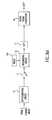
- an IQ radio receivercan be constructed according to Fig. 1, in which the radio signal S from the antenna 1 is applied directly to two balanced, quadrature mixers 2a, 2b (mathematically-multiplying devices) where the signal is multiplied respectively by a sine and cosine wave at the carrier frequency of signal S generated by a local oscillator 3.
- the multiplication devicesyield outputs containing both sum frequency components around 2f and difference frequency components around zero frequency.
- DC or low pass filters 4a, 4beliminate the former and accept the latter.
- the zero frequency componentscan then be amplified to any convenient level by low-frequency amplifying stages 5a, 5b instead of high frequency amplifiers.
- the zero-IF receivereliminates the interim conversion to an intermediate frequency by converting the incoming signal directly to baseband in a single operation.
- RF amplifierscan be added ahead of the mixers to raise the desired signal voltage level.
- a common source of the offsetis leakage from the local sinusoidal oscillator back to the antenna, producing coherent interference.
- RF amplificationis not a satisfactory solution because the desired signal and coherent interference are amplified equally.
- Another proposed solution used in conventional superheterodyne radio receiversis partial amplification of the input signal at the original antenna frequency.
- the partially amplified signalis then converted to a convenient intermediate frequency (IF) for further amplification before being applied to the balanced quadrature mixers.
- IFintermediate frequency
- the locally generated sine and cosine wavesare at the IF rather than the antenna frequency, so leakage back to the antenna is of no consequence.
- IF tuning circuitrythe simplicity and reduced size of the zero-IF receiver are lost.
- An alternative method of overcoming DC offset from the IQ mixersmay employ the technique variously called AC coupling, DC blocking, high-pass filtering or differentiation to eliminate the standing or DC offset voltage.
- the trade-off with this methodis the result that the DC and low-frequency components are lost or gravely distorted. This trade-off is unacceptable in digital transmission systems which use QPSK (Quadrature Phase Shift Keying) or MSK (Minimum Shift Keying) modulation techniques. These modulation techniques generate low frequency components that must be preserved.
- AN 83727325Russian Patent Abstracts, Section E1, Week 83/31, p. 6, Derwent Pubs. Ltd., representing SU-A-960 857 describes a data transmission extrapolator having an extra low frequency filter with input from device input and output to summator while storage element output is fed into first integrator.
- US-A-3 922 6060 at column 3, lines 16-52, and Fig. 2describes an adaptive delta modulation system having a comparator for comparing a signal with a feedback signal, a memory for storing a sequence of bits from the comparator, and a logic unit for generating up/down count signals for a counter. The decoded output of the counter is used to control an integrator.
- US-A-3 922 606does not relate to DC offset compensation, the first or precharacterizing parts of claims 17 and 28 are based thereon.
- US-A-4 944 025 at column 3, lines 9-44, and Fig. 1describes a direct conversion FM receiver that includes a local oscillator and two mixers associated with quadrature channels.
- US-A-4 944 025does not relate to DC offset compensation, the first or precharacterizing parts of claims 11, 12, 22, and 23 are based thereon.
- AU-B- 51G 022 at page 21, lines 14-22, and Fig. 1describes a reversible shift register 29 having a direction control input that is controlled by a decoder and having stage outputs used in the reconstruction of a discrete analog signal approximation.
- the present inventionrelates to zero-IF radio receivers designed to eliminate DC offset without distortion or loss of the low-frequency and DC components of the received or desired signal.
- the received signalis differentiated to filter out the DC offset.
- the signalis amplified to a suitable level and then integrated to recapture the original DC and low frequency signal components.
- the integrationessentially restores the filtered components to their original values in the amplified signal using an arbitrary constant of integration of bounded magnitude to generate a restored signal.
- the DC offsetcan be reasonably estimated.
- the DC offset estimateis then subtracted out of the restored signal leaving the amplified, received signal substantially free from distortion.
- An advantageous method for differentiating and digitizing the received signalutilizes a companded, delta modulation technique.
- the present inventionconcerns the removal of an unwanted DC offset voltage from a signal processing channel while preserving the DC and low-frequency components of the signal to be processed.
- the inventionis equally applicable to a single channel, to dual channels of the type encountered in quadrature or (IQ) types of radio receivers and to systems having more than two parallel processing channels.
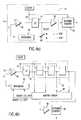
- Fig. 2(a)shows only one channel of a radio receiver, for example,the "I" channel of a dual channel IQ receiver. It is understood that the parallel "Q" channel, as well as additional parallel channels, have similar hardware components.
- the signal received from the in-phase mixeris applied to a differentiating circuit 10 which removes the DC offset voltage.
- the differentiation circuit 10also attenuates low frequency components of the desired signal, with respect to high frequency components, which distorts the nature of the signal. With the DC offset voltage removed, the desired signal is amplified in a low frequency amplifier 11 to usable levels without the premature amplifier saturation that occurs when such offsets are present.
- the output of the differentiating circuitis applied to an integrating circuit 12 which performs the inverse operation of differentiation.
- the output of the integrating circuit 12is referred to as the restored signal because it includes the amplified portion of the originally received signal as well as the low frequency and DC portions of the received signal (represented by the constant of integration).
- the in-phase (I) and quadrature (Q) signalscan be converted in an A-to-D converter 13 to digital form for further processing in a digital signal processor 14. Further processing can include phase demodulation, amplitude demodulation, or frequency demodulation. In principle, these demodulation processes can be implemented using software techniques as can other more complex demodulation processes for hybrid AM/PM phase modulation signals such as 256 QAM (quadrature AM).
- an arbitrary constant of integrationis used.
- the contents of the integration circuitare initially set to equal the known value.
- the integration circuit 12can also be readily reset to zero by activating a reset control 12a. After reset, the very first value output from the integration circuit 12 will be zero. In the situation where the actual value of the desired signal is zero initially, the output of the integration circuit 12 will be accurate from the start. At subsequent time periods, the differentiating and integrating operations cancel each other out.
- the output from the integration circuit 12will always be in error by a constant, (-VO).
- this error (-VO)is of the same order of magnitude as the desired signal.
- the originally input DC offset voltagemay have been several orders of magnitude greater than the desired signal. Consequently, the differentiation/integration of the desired signal eliminates premature amplifier saturation by preserving the DC component of the signal at manageable voltage levels.
- FIG. 2(b)Another preferred embodiment of the invention, shown in Fig. 2(b), concerns the removal of the offset error (-VO) by estimating the offset and subtracting it from the restored signal.
- an estimating circuit 15computes the offset error (-VO) during a period in which the desired signal is executing a known, deliberately inserted pattern or waveform.
- the estimating circuit 15may determine the offset using some natural or inherent property of the desired signal.
- this estimation processtakes place is set forth below. After estimation of the offset error, it is subtracted from the restored signal held in memory 16 in a subtracting circuit 17 to yield an error-free output signal. If the known portion of the desired signal does not occur at the beginning of the signal sequence, the known portion may be delayed or stored in the memory device 16 until the offset estimate is available.
- Deliberate signal patternIn a single-channel system, signal sequences might be arranged to include a known pattern +V, -V, +V, -V ... which ultimately has a mean of zero.
- the estimating circuit 15computes the mean of the restored signal over an even number of samples. Since the known mean is zero, the estimate of the offset (-VO) simply equals the computed mean.
- any known pattern of changing signal voltages(v1, v2, v3, v4 ...) can be used by employing the well known least-squares curve fitting technique. If the scaling of the signal is unknown, represented by the constant (a1) to be determined, the offset to be determined is represented by a0. During the period of a known signal pattern, the expected curve can be expressed mathematically as: a0 + a1.v1; a0 + a1.v2; a0 + a1.V3 .... Instead, the signals actually observed are (u1, u2, u3 ).
- the deliberate pattern used to estimate the offsets in the two channelscan take the form of a sequence of predetermined complex numbers.
- the unknown scaling factor, (a1)a real number in the single channel example, becomes a complex one, (c1).
- a complex scaling factor (c1)accounts for both an arbitrary amplitude scaling and arbitrary phase shift in transmission.
- a common form of radio signal processed by zero-IF or IQ receiversis a constant-envelope, modulated signal which varies only in phase, not amplitude.
- the unknown offsets in the I and Q channelsdisplace the center of this circle away from the origin (0, 0).
- Estimating the offset from a set of observed points (I1, Q1), (I2, Q2)...is accomplished by first determining the equation of a circle that best fits the observed points.
- the vector distance of the center of the best fit circle from the originprovides the necessary offset.
- This problemcan also be solved numerically in digital signal processor 14 (DSP) using least-squares fitting techniques.
- Figs. 3(a)-3(d)show several different embodiments for implementing the differentiation and integration functions of the block diagram circuit shown in Fig. 2(a).
- FIG. 3(a)illustrates an analog implementation of the differentiating and integration functions using operational amplifiers.
- An analog differentiator 10includes a capacitor 10a in series with an operational amplifier 10b, having a resistive feedback loop 10c. After amplification, the signal is fed to a simple integrator 12 composed of a feedback capacitor 12b in parallel with an operational amplifier 12c.
- a reset switch 12ais used to initialize the capacitor 12b voltage to zero at the beginning of a signal sequence.
- Fig. 3(b)shows an implementation of the differentiating and integrating circuit using only a single operational amplifier.
- a capacitor 10dessentially differentiates the incoming signal by blocking DC voltage.
- the capacitor 10d outputis then fed to an analog integrator 12 of the type shown in Fig. 3(a).
- Fig. 3(c)illustrates the use of a "chopper" technique to accomplish the same ends.
- a single capacitor 20performs both differentiation and integration.
- a blocking capacitor 20 connected in series with infinite impedance amplifiers 21,22generates only a change in the DC level of the input signal. That change equals the initial charge on the capacitor 20.
- the capacitortherefore functions as the mathematical equivalent of differentiation followed by integration which introduces an arbitrary constant shift in the DC portion of the input signal.
- FIG. 3(d)A preferred method of differentiating and integrating for many applications is shown in Fig. 3(d).
- the differentiationis carried out by an analog differentiator 10 similar to that shown in Fig. 3(a).
- the signalis then converted to digital form via an A-to-D converter 13.
- FIG. 3(e)A flow chart of the program control followed by the digital signal processor 14 to implement the integration function is illustrated in Fig. 3(e).
- the integration value uis preset to an initial value in this case u 0 is preset to 0.
- the sample count variable iis also preset to 0.
- Controlproceeds to block 102 where the digital output v i is read from the analog-to-digital converter 13.
- the sample variable countis incremented by 1.
- the digital integrationis performed in block 104 by adding the current digital sample v i to the previous integration value u i-1 to generate the current integration value u 1 .
- a decisionis made in block 106 to determine if enough samples have been accumulated. If not, the flow control returns to block 102.
- the advantage of digital integrationis that the integration may be preset with an exact, predetermined start value and does not suffer from noise or switching transients associated with the analog reset circuits. Moreover, the resetting can be accomplished partially to any desired value other than zero.
- Another advantage of a digital implementationis the offset estimates can be continuously updated during a continuous signal sequence rather than requiring a specific starting point to be identified.
- the differentiation procedure followed by an analog-to-digital conversionmay be implemented using a delta modulation technique.
- Delta modulationis a type of predictive quantitizing system equivalent to a one-digit differential pulse code modulation system. Such systems are based on transmission of the quantified difference between successive sample values rather than of the samples themselves. Consequently, a delta modulator estimates or predicts the input signal value based on the previously transmitted sequence of signals. A benefit of this technique is that only changes in the input voltage are digitized.
- An input signal Sis fed to a comparator 40.
- the other input to the comparator 40is the feedback output of an integrator 42.
- the output of the comparator 40either a digital "1" or "0" is latched in a D-type flip-flop 41 at the falling edge of every clock pulse CP.
- the digital bit sequence output from the flip-flop 41is fed back through a switch 44 having a positive or a negative current step connection to the integrator 42.
- the comparator 40detects a change in the input signal S relative to the integrator 42 feedback signal I and outputs a digital "1" when the amplitude of S exceeds I and a digital "0" when S is less than 1. Because the comparator 40 detects the change in signals, it effectively functions as a differentiator detecting only changes in the value of the signal.
- the flip-flop 41converts the output of the comparator 40 into a digital bit stream through a regular clock pulse CP. Thus, the comparator 40 and flip-flop 41 perform the function of an analog-to-digital converter.
- the flip-flop 41controls whether the current step inputs to the integrator 42 ramp the integrator output value up or down. A digital "1" causes the switch 44 to select a positive current step. Conversely, a digital "0" causes the switch to select a negative current step.
- the bit stream output from the flip-flop 41essentially represents the time derivative of the input signal S in digital form. Therefore, if the rate at which the decision to change the polarity sign of the current step is sufficiently high, the output value from the integrator 42 will be forced to follow the input signal quite closely.
- the output sequence from the flip-flop 41may require further amplification in an amplifier 49.
- a large part of the total system gainmay be achieved in the comparator 40 so that amplification of the signal elsewhere may be reduced.
- a good system designattempts to minimize the amplification needed prior to comparison by using a sensitive comparator because the prior gain stages have no protection against saturation from strong signal levels.
- each bit in the bit stream outputcan be characterized as an UP/DOWN command which can be monitored by an up/down counter 50, with a 1 corresponding to up and a 0 corresponding to down.
- the counteraccumulates the positive and negative changes of the input signal S with respect to the previous signal value, it performs the function of the integrating circuit 12 digitally.
- the count valueis equivalent to the integrated value plus some offset equivalent to the arbitrary constant of integration referred to in previous embodiments.
- delta modulationThere are two types of delta modulation, linear and adaptive.
- linear modulationthe value of the input signal at each sample time is predicted to be a particular linear function of the past values of the signal.
- adaptive delta modulationthe value of the input signal at each sample time is predicted to be a nonlinear function of the past values of the signal. Introducing nonlinear prediction into delta modulation provides a useful means of extending the range over which the system yields its optimum performance.
- Fig. 4(b)demonstrates the principle of an adaptive delta modulator.
- One of the benefits of this adaptive techniqueis that by integrating common companding techniques with delta modulation, the current step value input to the integrator 42 can adapt itself to the signal level being digitized. If the signal consists of a small varying part to be observed plus a large nonvarying part, e.g., the D.C. offset component, the system will initially produce an up-up-up or a down-down-down sequence of adjustment steps to the integrator 42 until the mean voltage equals the large, non-varying part of the input voltage.
- the sequence outputwould become 1 0 1 0 1 0 1 0 0 causing the size of the up-down steps to collapse and leaving the integrator mean voltage centered on the large non-varying portion of the input voltage.
- the step sizehas collapsed to the level of the small varying part of the signal, the output bit sequence will depend only on the varying part of the signal.
- the large, undesired D.C. componentis inherently differentiated using this process.
- the D.C. offset that is restoreddepends on the initial value that is stored in the digital integrator or accumulator. If the accumulator is initialized to 0 and the true signal value before corruption by the addition of the D.C. offset was indeed 0, then the true signal will be perfectly reproduced without the D.C. offset. However, if the accumulator is initialized to 0 and the true signal level is not 0 but some value, say 10 microvolts, then this 10 microvolt error will appear as a -10 microvolt offset or shift of the whole signal wave form after integration.
- the value of this errorhas been limited to the same order of magnitude as the desired signal, and therefore, can be handled in the digital signal processor 14 without saturation or clipping by estimating the value of the offset during a period of known, transmitted signal patterns. For example, if the true signal that is transmitted was 0 for several periods in the middle of a message transmission, but after integration a value in the middle of the wave form sequence of -13.5 microvolts was obtained, then it would be apparent that the differentiating-integration operation introduced an error of -13.5 microvolts. Accordingly, a value equivalent to 13.5 microvolts would be added to all of the digitized samples of the wave form before further processing.
- a shift register 45stores the three most recent outputs from the flip-flop 41. If desired, more or less outputs could be stored in a shift register having the desired number of bits.
- An adaptive circuit 46receives three bit signals stored in the shift register 45 and one bit signal from the flip-flop 41. Based on the results of the comparison in comparator 40, the adaptive circuit 46 outputs a positive or negative current step value to the digital integrator 42.
- the adaptive circuit 46determines whether to vary the value of the current step input to the integrator 42. For example, if the four bit values are 1 1 1 1, this indicates that the integrator 42 is not keeping pace with the increasing value of the incoming signal. Thus, when such a pattern is detected, the value of the positive current step is increased. On the other hand, if the four bit values are 0 0 0 0, the value of the negative current step is increased. In the situation where the register stores 1 0 1 0, a decision may be made by the adaptive circuit 46 that the step values are too large or coarse. The magnitude of the step value for both the positive and negative steps can then be decreased.
- the adaptive circuit 46may be a conventional microprocessor.
- the software for implementing the adaptive functionsmay be, for example, a well-known adaption algorithm used in continuously variable slope delta modulation systems (CVSD) for speech coding.
- CVSDcontinuously variable slope delta modulation systems
- This algorithmconsists of increasing the step size by a given amount whenever N-like bits appear sequentially at the output of the shift register 45.
- Nis typically 3 or 4 for speech coding purposes. For example, if N equals 4, the step sizes increase whenever the sequence 1 1 1 1 or 0 0 0 0 appears, indicating the system is not responding fast enough to drive the integrator 42 to follow the signal. Accordingly, the microprocessor or adaptive circuit 46 would increase the step size, rate, or slope by a predetermined value. Conversely, when the sequences 0 0 0 0 or 1 1 1 1 are not output from the shift register 45, the step size is allowed to decrease by exponential decay.
- An alternative algorithmmay also be implemented by the adaptive circuit 46 as published by V.D. Mytri and A.D. Shivaprasad, International Journal of Electronics, 1986, Volume 61, No. 1, pp. 129-133.
- This algorithmchanges the step size depending on the N last bits in a more general way. For example, if N equals 4, 16 different step size amounts for changing the step size may be selected according to the recent history of the four output bits. These 16 step size amounts are precomputed to optimize the system performance in terms of quantifying noise and reaction time to sudden increases in the signal level and may be stored, for example, in a look up table that is addressed by the four-most recent bits.
- Variance of the current step valueis a form of automatic gain control (AGC) that adapts the quantitizing steps to match the received signal level.
- AGCautomatic gain control
- the integrator 42must be incremented or decremented by a digital number corresponding to the step value rather than +1 or -1.
- the step valueis simply a function of the most recent output bit sequence and is readily determined by the adaptive circuit 46.
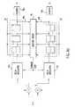
- Fig. 4(c)illustrates the use of the adaptive delta modulation technique in a zero-IF receiver.
- Each channel signalis input to its respective delta modulator 47a, 47b similar to that shown in Fig. 4(a).
- the output bit sequence from each modulatoris input to a corresponding shift register 45a, 45b which stores the most recent bits in the output sequence.
- the shift register outputsare input to a joint step-size adaptive circuit 46.
- the adaptive circuit 46determines the value of the current step to be input to the integrating circuit 42 of each channel based on the past bit sequence history of both channels. Jointly adapting the step value for each channel preserves the relative scaling of the I and Q channels which simplifies later computations of phase or frequency.
- Fig. 4 (d)shows the components of Fig. 4 (c) and estimating means 15, memory 16, and subtracting means 17 for estimating the DC offset and removing it as described above in connection with Figs. 2(b) and 3(a)-3(c).
Landscapes
- Engineering & Computer Science (AREA)
- Power Engineering (AREA)
- Computer Networks & Wireless Communication (AREA)
- Signal Processing (AREA)
- Digital Transmission Methods That Use Modulated Carrier Waves (AREA)
- Noise Elimination (AREA)
- Radar Systems Or Details Thereof (AREA)
- Circuits Of Receivers In General (AREA)
- Dc Digital Transmission (AREA)
Description
0 0 0 0, the value of the negative current step is increased. Inthe situation where the register stores
1 0 1 0, a decision may be made by the
Claims (30)
- In a radio receiver, an apparatus for compensatingfor DC offset in a received signal, comprising:characterized in that the apparatus further comprises:means for generating a channel signal from a receivedradio signal;blocking means (10) for blocking the DC component ofthe channel signal;amplifying means (11), connected to said blockingmeans, for amplifying a signal output from said blocking meansand producing an amplified signal;restoring means (12), connected to said amplifyingmeans, for restoring said DC component to said amplified signal,said restoring means having an output for a restored signalincluding said amplified signal and said DC component;means (15), connected to the output of said restoringmeans, for estimating an error in the restored DC component;memory means (16), connected to the restoring means,for storing the restored signal; andsubtracting means (17), connected to said estimatingmeans and said memory means, for subtracting the estimated errorfrom the restored signal to thereby substantially free the signaloutput from said subtracting means from low frequency distortion.
- The apparatus as defined in claim 1, wherein saidestimating means includes a digital signal processor (14) fordetermining the error in the restored DC component based on a predetermined signal pattern inthe channel signal.
- The apparatus as defined in claim 1, wherein saidestimating means includes a digital signal processor (14) fordetermining the error in the restored DC component based on an inherent waveformcharacteristic of the channel signal.
- The apparatus as defined in claim 1, wherein saidblocking means includes a delta modulator (47) for blocking DCsignal components and digitizing the channel signal.
- The apparatus as defined in claim 1, wherein theblocking means comprises means (10) for differentiating thechannel signal to eliminate the DC component in the channelsignal; and the restoring means comprises means (12) forintegrating the amplified signal to thereby recover said DCcomponent.
- In a radio receiver, an apparatus for compensatingfor DC offset in a received signal, comprising:means for generating a channel signal from a receivedradio signal;blocking and restoring means (20) for blocking the DCcomponent of the channel signal and restoring said DC componentto said received radio signal, characterized in that saidblocking and restoring means comprises means for differentiatingthe channel signal to eliminate the DC component in the channelsignal and means for integrating the channel signal to therebyrecover said DC component, both said differentiating andintegrating means consisting of a single capacitor (20), and in that theapparatus further comprises:amplifying means (22), connected to said blocking andrestoring means, for amplifying a signal output from saidblocking and restoring means and producing an amplified signal;means (15), connected to the output of said amplifyingmeans, for estimating an error in the amplified signal;memory means (16), connected to the amplifying means,for storing the amplified signal; andsubtracting means (17), connected to said estimatingmeans and said memory means, for subtracting the estimated errorfrom the amplified signal to thereby substantially free thesignal output from said subtracting means from low frequencydistortion.
- The apparatus as defined in claim 5, furthercomprising:an analog-to-digital converter (13) for converting theoutput from said amplifying means to digital signals, and said integrating means includes means (14) for numerically integratingthe digital signals output from said analog-to-digital converter.
- The apparatus as defined in claim 7, wherein saiddifferentiating means and said analog-to-digital converterinclude a delta modulator (47).
- The apparatus as defined in claim 5, wherein saidestimating means includes a digital signal processor (14) fordetermining the estimate of the error in the recovered DCcomponent based on a predetermined signal pattern in the channelsignal.
- The apparatus as defined in claim 5, wherein saidestimating means includes a digital signal processor (14) fordetermining the estimate of the error in the recovered DCcomponent based on an inherent characteristic of the channelsignal.
- A radio receiving apparatus for receiving an RFsignal and applying said RF signal to first and second quadraturechannels, comprising:characterized in that the radio receiving apparatusfurther comprises:a local oscillator; andfirst and second mixers, associated with said first andsecond quadrature channels, respectively, each having one inputfor receiving said RF signal and a second input for receivingfrom said local oscillator sinusoidal signals at a carrierfrequency of said RF signal;first and second differentiating means (10) forrespectively differentiating outputs from said first and secondmixers in order to eliminate DC offset components generated byimbalances between said first and second mixers;first and second amplifying means (11) for respectivelyamplifying outputs from said first and second differentiatingmeans;first and second integrating means (12) forrespectively integrating outputs from said first and secondamplifying means to restore DC offset components of said outputsfrom said first and second mixers;means (15), connected to outputs of said first andsecond integrating means, for estimating errors in said restoredDC offset components;memory means (16), connected to said first and secondintegrating means, for storing signals from said first and secondintegrating means; andmeans (17) for combining said estimated errors withsaid stored signals to thereby substantially free the output ofthe combining means from low frequency distortion.
- A radio receiving apparatus for receiving an RF signaland applying said RF signal to first and second quadraturechannels, comprising:characterized in that the radio receiving apparatusfurther comprises:a local oscillator; andfirst and second mixers, associated with said first andsecond quadrature channels, respectively, each having one inputfor receiving said RF signal and a second input for receivingfrom said local oscillator sinusoidal signals at a carrierfrequency of said RF signal;first and second differentiating and integrating means(20) for respectively differentiating outputs from said first andsecond mixers in order to eliminate DC offset componentsgenerated by imbalances between said first and second mixers andrespectively integrating outputs from said first and secondmixers to restore DC offset components of said outputs from saidfirst and second mixers, said first and second differentiatingand integrating means each respectively consisting of a singlecapacitor (20);first and second amplifying means (22) for respectivelyamplifying outputs from said first and second differentiating andintegrating means;means (15), connected to outputs of said first andsecond amplifying means, for estimating errors in said restored DC offset components;memory means (16), connected to outputs of said firstand second amplifying means, for storing signals from said firstand second amplifying means; andmeans (17) for combining said estimated errors withsaid stored signals to thereby substantially free the output ofthe combining means from low frequency distortion.
- The apparatus as defined in claim 11, wherein saidfirst and second differentiating means include a delta modulator(47) for differentiating the outputs of said first and secondmixers and for digitizing the differentiated outputs.
- The apparatus as defined in claim 13, wherein saidfirst and second integrating means include a digital signalprocessor (14) for numerically integrating the outputs from saidfirst and second amplifiers.
- The apparatus as defined in claim 11, wherein saidestimating means includes a digital signal processor (14) fordetermining said errors in the restored DC offset componentsbased on a predetermined signal pattern in the received RFsignal.
- The apparatus as defined in claim 11, wherein saidestimating means includes a digital signal processor (14) fordetermining said errors in the restored DC offset componentsbased on an inherent characteristic of said received RF signal.
- In a radio receiver, an apparatus for compensating forDC offset in a received signal, comprising:characterized in that the apparatus further comprises secondintegrating means (50) for receiving said digital values fromsaid memory means and for integrating said digital values inorder to restore DC components of said received signal;comparator means (40) for comparing a received signal witha feedback signal and for generating a first digital value ifsaid received signal exceeds said feedback signal and a seconddigital value if said received signal is less than said feedbacksignal;memory means (45) for storing a sequence of digital valuesoutput from said comparator means;deciding means (46), connected to said memory means, for receiving said sequence of digital values and for deciding acurrent step value; andfirst integrating means (42) for integrating current stepvalues received from said deciding means and for generating saidfeedback signal;means (15), connected to the output of said secondintegrating means, for estimating an error in the restored DC components;further memory means (16), connected to said second integratingmeans, for storing the restored signal; andsubtracting means (17), connected to said estimating meansand said further memory means, for subtracting the estimated error fromthe restored signal to thereby substantially free the signaloutput from said subtracting means from low frequency distortion.
- The apparatus according to claim 17, wherein saiddigital values represent the digitized derivative of saidreceived signal.
- The apparatus according to claim 17, wherein saidsecond integrating means includes an up/down counter means forcounting up when a first digital signal is received and down whena second digital signal is received.
- The apparatus according to claim 17, wherein saidcurrent step values are positive and negative step values basedon said sequence of digital values.
- The apparatus according to claim 20, wherein saiddeciding means increases and decreases the magnitude of saidpositive and negative step values based on predetermined patternsin said sequence.
- A radio receiving apparatus for receiving an RFsignal and applying said RF signal to first and second quadraturechannels, comprising means for receiving said RF signal and separating said RF signal into first and second quadraturesignals,
characterized in that the radio receiving apparatusfurther comprises:first and second comparator means (40) for comparingsaid first and second quadrature signals with first and secondfeedback signals respectively, and for generating a first digitalvalue if said received signal exceeds said feedback signal anda second digital value if said received signal is less than saidfeedback signal;first and second memory means (45) for storingcorresponding sequences of said digital values generated by saidfirst and second comparator means, respectively;first and second deciding means (46), connected to saidfirst and second memory means, for receiving said sequences ofdigital values and for deciding a joint current step value;first and second integrating means (42) for integratingjoint current step values received from said deciding means andfor generating said first and second feedback signals which aresent to said first and second comparator means, respectively;first and second reintegrating means (50) forreintegrating said corresponding digital values received fromsaid first and second memory means in order to restore DCcomponents of said received signal;first and second means (15), connected to the outputsof said first and second reintegrating means (50) for estimatingerrors in the restored DC components;further first and second memory means (16) connected to theoutputs of said first and second reintegrating means (50) forstoring the restored signals; andfirst and second subtracting means (17) connected tosaid first and second estimating means and further memory means forsubtracting the estimated errors from the restored signals tothereby substantially free the signals output from said first andsecond subtracting means from low frequency distortion. - A radio receiver for receiving an RF signal andapplying said RF signal to plural channels, comprising:
means for receiving said RF signal and separating said RF signals into a plurality of channel signals,
characterized in that the radio receiver furthercomprises:plural delta modulating means (47) for receivingrespective channel signals, each delta modulating meansgenerating a digital output;plural memory means (45) for storing digital sequencesof digital outputs from corresponding ones of said plural deltamodulating means;adaptive means (46), connected to said plural memorymeans, for adapting step value signals fed back to correspondingones of said plural delta modulating means;plural reintegrating means (50) for integrating acorresponding digital output received from corresponding ones ofsaid plural memory means in order to restore DC components ofsaid channel signals;plural means (15), connected to the outputs of saidplural reintegrating means (50), for estimating errors in the restored DCcomponents;plural further memory means (16) connected to said pluralreintegrating means (50) for storing signals from said pluralreintegrating means; andplural means (17) for algebraically combining saidestimated errors in the restored DC components with said stored signals tothereby substantially free the output of each combining meansfrom low frequency distortion. - The apparatus according to claim 23, wherein saidstep value signals are identical for each delta modulating meansand any adaptation by said adaptive means is uniformly appliedto said step value signals.
- The apparatus according to claim 23, wherein eachof said plural delta modulating means includes:comparator means (40) for comparing a respectivechannel signal with a feedback RF signal and for generating afirst digital value if said RF received signal exceeds saidfeedback signal and a second digital signal value if saidreceived RF signal is less than said feedback signal in order to restore DC components of said channel signal;clock means for generating a clock pulse;latch means (41), connected to said clock means, forlatching a sequence of digital values output from said comparatormeans at each clock pulse;selecting means (44), connected to said latch means,for receiving said sequence of digital values and for selectinga positive or a negative current step; andintegrator means (42) for integrating current stepvalues received from said selecting means and for outputting saidfeedback signal to said comparator means.
- The apparatus as defined in claim 23, wherein saidplural estimating means include processing means for determiningsaid errors in the restored DC components based on a predetermined signalin said received RF signal.
- The apparatus as defined in claim 23, wherein saidestimating means include processing means for determining saiderrors in the restored DC components based on an inherent characteristicof said received RF signal.
- A method for compensating for DC offset in an signalreceived in a multi-channel RF receiver, comprising the steps of:characterized in that the method further comprisesthe steps of:comparing a received signal with a feedback signal andgenerating a first digital value if said received signal exceedssaid feedback signal and a second digital value if said receivedsignal is less than said feedback signal;storing a sequence of said digital values producedin said comparing step;determining a current step value based on saidsequence of digital values; andintegrating said current step value and generating saidfeedback signal;reintegrating said digital values stored at saidstoring step in-order to restore DC components of said receivedsignal;estimating errors in the restored DC components;storing the restored signals; andsubtracting the estimated errors from the restored signalsto thereby substantially free the output resulting from the substraction from lowfrequency distortion.
- The method according to claim 28, further characterizedby the step of:increasing the magnitude of said current step value basedon predetermined patterns of said sequence.
- The method according to claim 28, further characterizedby the step of decreasing the magnitude of said current stepvalue based on predetermined patterns of said sequence.
Applications Claiming Priority (2)
| Application Number | Priority Date | Filing Date | Title |
|---|---|---|---|
| US07/578,251US5241702A (en) | 1990-09-06 | 1990-09-06 | D.c. offset compensation in a radio receiver |
| US578251 | 2000-05-24 |
Publications (3)
| Publication Number | Publication Date |
|---|---|
| EP0474615A2 EP0474615A2 (en) | 1992-03-11 |
| EP0474615A3 EP0474615A3 (en) | 1992-10-28 |
| EP0474615B1true EP0474615B1 (en) | 1998-03-04 |
Family
ID=24312055
Family Applications (1)
| Application Number | Title | Priority Date | Filing Date |
|---|---|---|---|
| EP91850216AExpired - LifetimeEP0474615B1 (en) | 1990-09-06 | 1991-09-05 | D.C. offset compensation in a radio receiver |
Country Status (12)
| Country | Link |
|---|---|
| US (1) | US5241702A (en) |
| EP (1) | EP0474615B1 (en) |
| JP (1) | JPH05316158A (en) |
| AU (1) | AU644208B2 (en) |
| CA (1) | CA2050666C (en) |
| DE (1) | DE69128991T2 (en) |
| ES (1) | ES2115609T3 (en) |
| FI (1) | FI108587B (en) |
| HK (1) | HK1009363A1 (en) |
| MX (1) | MX9100956A (en) |
| NZ (1) | NZ239628A (en) |
| TW (1) | TW201368B (en) |
Cited By (2)
| Publication number | Priority date | Publication date | Assignee | Title |
|---|---|---|---|---|
| US7190740B2 (en) | 2002-08-19 | 2007-03-13 | Siemens Communications, Inc. | Arrangement for dynamic DC offset compensation |
| US7212587B2 (en) | 2000-08-04 | 2007-05-01 | Freescale Semiconductor, Inc. | Apparatus for reducing DC offset in a receiver |
Families Citing this family (105)
| Publication number | Priority date | Publication date | Assignee | Title |
|---|---|---|---|---|
| US5241702A (en)* | 1990-09-06 | 1993-08-31 | Telefonaktiebolaget L M Ericsson | D.c. offset compensation in a radio receiver |
| GB2267629B (en)* | 1992-06-03 | 1995-10-25 | Fujitsu Ltd | Signal error reduction in receiving apparatus |
| GB9211712D0 (en)* | 1992-06-03 | 1992-07-15 | Fujitsu Microelectronics Ltd | Gm digital receive processing |
| DE69228816T2 (en)* | 1992-10-28 | 1999-08-19 | Alcatel | DC offset correction for direct mix TDMA receivers |
| SE502599C2 (en)* | 1993-09-09 | 1995-11-20 | Ericsson Ge Mobile Communicat | Methods and devices at a homo pad receiver to minimize leakage of interference signals |
| US5461340A (en)* | 1993-09-11 | 1995-10-24 | Robert Bosch Gmbh | Amplitude demodulator for radio receivers to compensate for field strength influence |
| JP3565281B2 (en)* | 1993-10-08 | 2004-09-15 | ソニー株式会社 | Receiving machine |
| GB2288936B (en)* | 1993-10-14 | 1997-09-24 | Ericsson Ge Mobile Communicat | Adaptive bandwidth receiver |
| US5668837A (en)* | 1993-10-14 | 1997-09-16 | Ericsson Inc. | Dual-mode radio receiver for receiving narrowband and wideband signals |
| DE4341937A1 (en)* | 1993-12-09 | 1995-06-14 | Philips Patentverwaltung | Electrical device with an arrangement for compensation of a DC voltage component |
| US5539730A (en)* | 1994-01-11 | 1996-07-23 | Ericsson Ge Mobile Communications Inc. | TDMA/FDMA/CDMA hybrid radio access methods |
| US5708971A (en)* | 1994-01-11 | 1998-01-13 | Ericsson Inc. | Two-way paging system and apparatus |
| US5943324A (en)* | 1994-01-11 | 1999-08-24 | Ericsson, Inc. | Methods and apparatus for mobile station to mobile station communications in a mobile satellite communication system |
| ZA95605B (en)* | 1994-04-28 | 1995-12-20 | Qualcomm Inc | Method and apparatus for automatic gain control and dc offset cancellation in quadrature receiver |
| US5459679A (en)* | 1994-07-18 | 1995-10-17 | Quantum Corporation | Real-time DC offset control and associated method |
| US7904722B2 (en)* | 1994-07-19 | 2011-03-08 | Certco, Llc | Method for securely using digital signatures in a commercial cryptographic system |
| US5471665A (en)* | 1994-10-18 | 1995-11-28 | Motorola, Inc. | Differential DC offset compensation circuit |
| FI972475L (en)* | 1994-12-12 | 1997-08-12 | Ericsson Ge Mobile Inc | Diversity-oriented channel allocation in a mobile communication system |
| US5724653A (en)* | 1994-12-20 | 1998-03-03 | Lucent Technologies Inc. | Radio receiver with DC offset correction circuit |
| US5579347A (en)* | 1994-12-28 | 1996-11-26 | Telefonaktiebolaget Lm Ericsson | Digitally compensated direct conversion receiver |
| DE69624020T2 (en)* | 1995-02-21 | 2003-07-17 | Tait Electronics Ltd., Christchurch | Zero intermediate frequency receiver |
| US5614904A (en)* | 1995-03-09 | 1997-03-25 | Ericsson Inc. | Balance companded delta conversion for homodyne receiver |
| US5568520A (en)* | 1995-03-09 | 1996-10-22 | Ericsson Inc. | Slope drift and offset compensation in zero-IF receivers |
| US5715414A (en)* | 1995-06-27 | 1998-02-03 | Rohm Co., Ltd. | Four-value data wireless signal receiver |
| JPH0918528A (en)* | 1995-06-27 | 1997-01-17 | Sony Corp | Control signal detecting method and radio reception device |
| US5646569A (en)* | 1995-08-30 | 1997-07-08 | Hewlett-Packard Company | Method and apparatus for AC coupling |
| US5862173A (en)* | 1995-12-11 | 1999-01-19 | Ericsson Inc. | Re-orthogonalization of wideband CDMA signals |
| GB2310115B (en)* | 1996-02-08 | 2000-06-07 | Nokia Mobile Phones Ltd | Method and apparatus for dc compensation |
| US5838735A (en)* | 1996-07-08 | 1998-11-17 | Telefonaktiebolaget Lm Ericsson | Method and apparatus for compensating for a varying d.c. offset in a sampled signal |
| US5749051A (en)* | 1996-07-18 | 1998-05-05 | Ericsson Inc. | Compensation for second order intermodulation in a homodyne receiver |
| US5896375A (en)* | 1996-07-23 | 1999-04-20 | Ericsson Inc. | Short-range radio communications system and method of use |
| US5918169A (en)* | 1996-09-25 | 1999-06-29 | Ericsson, Inc. | Homodyne cellular base station |
| US5818872A (en)* | 1996-12-31 | 1998-10-06 | Cirrus Logic, Inc. | Timing offset error extraction method and apparatus |
| US6633550B1 (en) | 1997-02-20 | 2003-10-14 | Telefonaktiebolaget Lm Ericsson (Publ) | Radio transceiver on a chip |
| US5852772A (en)* | 1997-02-25 | 1998-12-22 | Ericsson Inc. | Receiver IF system with active filters |
| DE69818327T2 (en) | 1997-03-05 | 2004-07-01 | Nec Corp. | Direct mixer receiver for suppression of offset DC voltages |
| JP3475037B2 (en)* | 1997-03-14 | 2003-12-08 | 株式会社東芝 | transceiver |
| US6259904B1 (en)* | 1997-10-06 | 2001-07-10 | Motorola, Inc. | Fast squelch circuit and method |
| US6516187B1 (en) | 1998-03-13 | 2003-02-04 | Maxim Integrated Products, Inc. | DC offset correction for direct conversion tuner IC |
| US6205183B1 (en) | 1998-05-29 | 2001-03-20 | Ericsson Inc. | Methods of suppressing reference oscillator harmonic interference and related receivers |
| US7065327B1 (en) | 1998-09-10 | 2006-06-20 | Intel Corporation | Single-chip CMOS direct-conversion transceiver |
| CA2356699C (en) | 1998-12-24 | 2008-02-05 | Telefonaktiebolaget Lm Ericsson | Communication receiver having reduced dynamic range |
| US6567475B1 (en) | 1998-12-29 | 2003-05-20 | Ericsson Inc. | Method and system for the transmission, reception and processing of 4-level and 8-level signaling symbols |
| SE9900289D0 (en) | 1999-01-27 | 1999-01-27 | Ericsson Telefon Ab L M | DC estimate method for a homodyne receiver |
| GB2346777B (en)* | 1999-02-12 | 2004-04-07 | Nokia Mobile Phones Ltd | DC offset correction in a direct conversion receiver |
| DE60001960T2 (en)* | 1999-05-24 | 2003-11-13 | Level One Communications, Inc. | AUTOMATIC GAIN CONTROL AND OFFSET CORRECTION |
| US6563892B1 (en) | 1999-06-15 | 2003-05-13 | Telefonaktiebolaget Lm Ericsson | Method and system for detection of binary information in the presence of slowly varying disturbances |
| US6370205B1 (en)* | 1999-07-02 | 2002-04-09 | Telefonaktiebolaget Lm Ericsson (Publ) | Method and apparatus for performing DC-offset compensation in a radio receiver |
| US6449320B1 (en)* | 1999-07-02 | 2002-09-10 | Telefonaktiebolaget Lm Ericsson (Publ) | Equalization with DC-offset compensation |
| JP4123320B2 (en)* | 1999-09-17 | 2008-07-23 | ソニー株式会社 | Receiver and its IC |
| GB2355900B (en) | 1999-10-29 | 2004-03-17 | Ericsson Telefon Ab L M | Radio receiver |
| WO2001043122A2 (en) | 1999-12-10 | 2001-06-14 | Seagate Technology Llc | Magnetic disc having physical servo patterns with a magnetic carrier, and method of making and using the same |
| US6625236B1 (en) | 2000-02-08 | 2003-09-23 | Ericsson Inc. | Methods and systems for decoding symbols by combining matched-filtered samples with hard symbol decisions |
| US6643336B1 (en)* | 2000-04-18 | 2003-11-04 | Widcomm, Inc. | DC offset and bit timing system and method for use with a wireless transceiver |
| JP4179782B2 (en) | 2000-04-26 | 2008-11-12 | 富士通株式会社 | Radio receiving apparatus and radio communication system |
| US6868128B1 (en) | 2000-07-05 | 2005-03-15 | Rfmd Wpan, Inc. | Method and apparatus for calibrating DC-offsets in a direct conversion receiver |
| GB2366460A (en)* | 2000-08-24 | 2002-03-06 | Nokia Mobile Phones Ltd | DC compensation for a direct conversion radio receiver |
| US6560448B1 (en)* | 2000-10-02 | 2003-05-06 | Intersil Americas Inc. | DC compensation system for a wireless communication device configured in a zero intermediate frequency architecture |
| US7068987B2 (en) | 2000-10-02 | 2006-06-27 | Conexant, Inc. | Packet acquisition and channel tracking for a wireless communication device configured in a zero intermediate frequency architecture |
| US6735422B1 (en)* | 2000-10-02 | 2004-05-11 | Baldwin Keith R | Calibrated DC compensation system for a wireless communication device configured in a zero intermediate frequency architecture |
| US6654593B1 (en)* | 2000-10-30 | 2003-11-25 | Research In Motion Limited | Combined discrete automatic gain control (AGC) and DC estimation |
| DE60024831T2 (en)* | 2000-10-30 | 2006-08-03 | Texas Instruments Inc., Dallas | Apparatus for compensating the DC offset of a quadrature demodulator, and method therefor |
| EP1202511B1 (en)* | 2000-10-30 | 2006-01-11 | Texas Instruments France | Method for estimating and removing a time-varying DC-offset |
| US6907235B2 (en)* | 2001-01-02 | 2005-06-14 | Texas Instruments Incorporated | Apparatus and method for canceling DC offset in communications signals |
| US6845126B2 (en)* | 2001-01-26 | 2005-01-18 | Telefonaktiebolaget L.M. Ericsson (Publ) | System and method for adaptive antenna impedance matching |
| US6961368B2 (en)* | 2001-01-26 | 2005-11-01 | Ericsson Inc. | Adaptive antenna optimization network |
| US7522900B2 (en)* | 2001-03-20 | 2009-04-21 | Broadcom Corporation | DC offset correction for use in a radio architecture |
| US6535725B2 (en)* | 2001-03-30 | 2003-03-18 | Skyworks Solutions, Inc. | Interference reduction for direct conversion receivers |
| WO2002084859A1 (en)* | 2001-04-18 | 2002-10-24 | Nokia Corporation | Balanced circuit arrangement and method for linearizing such an arrangement |
| ATE460769T1 (en)* | 2001-09-28 | 2010-03-15 | Nxp Bv | GILBERT MULTIPLIER CELL MIXER |
| US7356326B2 (en)* | 2001-12-12 | 2008-04-08 | Samsung Electronics Co., Ltd. | Direct-conversion receiver for removing DC offset |
| US7038733B2 (en) | 2002-01-30 | 2006-05-02 | Ericsson Inc. | Television receivers and methods for processing signal sample streams synchronously with line/frame patterns |
| CN100490304C (en)* | 2002-02-01 | 2009-05-20 | Nxp股份有限公司 | Detection of additive DC component contained in input burst signal |
| GB0206764D0 (en)* | 2002-03-22 | 2002-05-01 | Koninkl Philips Electronics Nv | DC offset removal in a wireless receiver |
| US7536165B2 (en)* | 2002-07-24 | 2009-05-19 | Nxp B.V. | Offset correction for down-conversion mixers |
| US7139546B1 (en) | 2003-04-29 | 2006-11-21 | Ami Semiconductor, Inc. | Up-conversion of a down-converted baseband signal in a direct conversion architecture without the baseband signal passing through active elements |
| US7113760B1 (en) | 2003-04-29 | 2006-09-26 | Ami Semiconductor, Inc. | Direct conversion receiver for amplitude modulated signals using linear/log filtering |
| US7006809B2 (en) | 2003-05-06 | 2006-02-28 | Ami Semiconductor, Inc. | Adaptive diversity receiver architecture |
| US7197091B1 (en) | 2003-05-06 | 2007-03-27 | Ami Semiconductor, Inc. | Direct conversion receiver with direct current offset correction circuitry |
| US7215722B2 (en)* | 2003-06-09 | 2007-05-08 | Ali Corporation | Device for WLAN baseband processing with DC offset reduction |
| US7336938B1 (en)* | 2003-06-18 | 2008-02-26 | National Semiconductor Corporation | Phase-alternating mixer with alias and harmonic rejection |
| SE0302156D0 (en)* | 2003-08-01 | 2003-08-01 | Infineon Technologies Ag | Low-latency DC compensation |
| US6909388B1 (en) | 2004-06-23 | 2005-06-21 | Microchip Technology Incorporated | Fractal sequencing schemes for offset cancellation in sampled data acquisition systems |
| US20060145853A1 (en)* | 2004-12-22 | 2006-07-06 | Time Domain Corporation | System and method for detecting objects and communicating information |
| US7653359B2 (en)* | 2006-01-20 | 2010-01-26 | Broadcom Corporation | Techniques to decrease fractional spurs for wireless transceivers |
| US7647026B2 (en)* | 2006-02-16 | 2010-01-12 | Broadcom Corporation | Receiver architecture for wireless transceiver |
| US8218693B2 (en)* | 2006-03-09 | 2012-07-10 | Broadcom Corporation | Gain control for wireless receiver |
| US8467473B2 (en)* | 2006-03-31 | 2013-06-18 | Broadcom Corporation | Power control techniques for wireless transmitters |
| US7933361B2 (en)* | 2006-04-05 | 2011-04-26 | Integrated System Solution Corp. | Hybrid DC-offset reduction method and system for direct conversion receiver |
| US7555279B2 (en)* | 2006-07-24 | 2009-06-30 | General Dynamics C4 Systems | Systems and methods for DC offset correction in a direct conversion RF receiver |
| US7622987B1 (en) | 2007-01-25 | 2009-11-24 | Pmc-Sierra, Inc. | Pattern-based DC offset correction |
| US20090097452A1 (en)* | 2007-10-12 | 2009-04-16 | Qualcomm Incorporated | Femto cell synchronization and pilot search methodology |
| US20090149202A1 (en)* | 2007-12-07 | 2009-06-11 | Christian Steele | System and method for determination of position |
| US8295304B1 (en) | 2007-12-27 | 2012-10-23 | Exalt Communications Incorporated | Adaptive multi-service data framing |
| US8428186B1 (en)* | 2007-12-27 | 2013-04-23 | Exalt Communications Incorporated | Decision directed DC offset removal |
| GB0803710D0 (en)* | 2008-02-28 | 2008-04-09 | Nokia Corp | DC compensation |
| US8351874B2 (en)* | 2008-04-08 | 2013-01-08 | Telefonaktiebolaget Lm Ericsson (Publ) | System and method for adaptive antenna impedance matching |
| US7995973B2 (en)* | 2008-12-19 | 2011-08-09 | Telefonaktiebolaget Lm Ericsson (Publ) | Own transmitter interference tolerant transceiver and receiving methods |
| US8055234B2 (en)* | 2008-06-27 | 2011-11-08 | Telefonaktiebolaget Lm Ericsson (Publ) | Methods and apparatus for suppressing strong-signal interference in low-IF receivers |
| US8855580B2 (en)* | 2008-06-27 | 2014-10-07 | Telefonaktiebolaget L M Ericsson (Publ) | Methods and apparatus for reducing own-transmitter interference in low-IF and zero-IF receivers |
| US8090320B2 (en)* | 2008-12-19 | 2012-01-03 | Telefonaktiebolaget Lm Ericsson (Publ) | Strong signal tolerant OFDM receiver and receiving methods |
| US8611356B2 (en) | 2009-11-13 | 2013-12-17 | Exalt Communications Incorporated | Apparatus for ethernet traffic aggregation of radio links |
| US20110176641A1 (en) | 2010-01-20 | 2011-07-21 | St-Ericsson Sa | D.C. Offset Estimation |
| WO2016142424A1 (en)* | 2015-03-09 | 2016-09-15 | Sony Corporation | Device and method for determining a dc component |
| GB201907717D0 (en)* | 2019-05-31 | 2019-07-17 | Nordic Semiconductor Asa | Apparatus and methods for dc-offset estimation |
Family Cites Families (28)
| Publication number | Priority date | Publication date | Assignee | Title |
|---|---|---|---|---|
| US3922606A (en)* | 1974-04-08 | 1975-11-25 | Dicom Systems | Adaptive delta modulation information transmission system |
| US3953805A (en)* | 1974-11-07 | 1976-04-27 | Texas Instruments Incorporated | DC component suppression in zero CF IF systems |
| GB1556087A (en)* | 1977-12-01 | 1979-11-21 | Standard Telephones Cables Ltd | Single channel duplex radio system |
| AU516022B2 (en)* | 1978-09-04 | 1981-05-14 | Western Electric Co. Inc. | Differed ial pgm encoder |
| US4258327A (en)* | 1979-07-05 | 1981-03-24 | Rca Corporation | Detector circuit with integrating feedback means |
| NL8000883A (en)* | 1980-02-13 | 1981-09-16 | Philips Nv | COHERENT RECEIVER FOR ANGLE MODULATED DATA SIGNALS. |
| US4345211A (en)* | 1980-09-15 | 1982-08-17 | Rockwell International Corporation | Digital phaselock demodulator |
| US4476585A (en)* | 1982-01-25 | 1984-10-09 | International Telephone And Telegraph Corporation | Baseband demodulator for FM signals |
| US4454604A (en)* | 1982-04-02 | 1984-06-12 | Motorola Inc. | Virtual time base direct synchronizer and method therefor |
| FR2525055A1 (en)* | 1982-04-09 | 1983-10-14 | Trt Telecom Radio Electr | METHOD OF CORRECTING FREQUENCY OF THE LOCAL CARRIER IN THE RECEIVER OF A DATA TRANSMISSION SYSTEM AND RECEIVER USING THE SAME |
| DE3346725A1 (en)* | 1983-12-23 | 1985-07-04 | Robert Bosch Gmbh, 7000 Stuttgart | Compensation circuit for a data modulator |
| FR2564663B1 (en)* | 1984-05-15 | 1986-09-19 | Radiotechnique | FREQUENCY DEMODULATOR WITH ADJUSTABLE BANDWIDTH |
| US4726069A (en)* | 1984-05-18 | 1988-02-16 | Stevenson Carl R | A muiti-mode modulation and demodulation system and method |
| US4731796A (en)* | 1984-10-25 | 1988-03-15 | Stc, Plc | Multi-mode radio transceiver |
| US4893316A (en)* | 1985-04-04 | 1990-01-09 | Motorola, Inc. | Digital radio frequency receiver |
| DE3516492A1 (en)* | 1985-05-08 | 1986-11-13 | Standard Elektrik Lorenz Ag, 7000 Stuttgart | RADIO RECEIVER |
| GB2175473A (en)* | 1985-05-17 | 1986-11-26 | Philips Electronic Associated | D.c. block capacitor circuit |
| GB2193405A (en)* | 1986-08-01 | 1988-02-03 | Philips Electronic Associated | Demodulating an angle-modulated signal |
| US4736390A (en)* | 1986-10-15 | 1988-04-05 | Itt Avionics, A Division Of Itt Corporation | Zero IF radio receiver apparatus |
| US4811425A (en)* | 1987-01-09 | 1989-03-07 | Itt Avionics, A Division Of Itt Corporation | Apparatus for reducing the effects of local oscillator leakage in mixers employed in zero IF receivers |
| EP0324581A3 (en)* | 1988-01-13 | 1990-11-07 | Hewlett-Packard Company | Calibration of vector demodulator using statistical analysis |
| GB2215545A (en)* | 1988-03-16 | 1989-09-20 | Philips Electronic Associated | A direct-conversion receiver |
| DE3889326D1 (en)* | 1988-05-27 | 1994-06-01 | Itt Ind Gmbh Deutsche | Correction circuit for a digital quadrature signal pair. |
| US4944025A (en)* | 1988-08-09 | 1990-07-24 | At&E Corporation | Direct conversion FM receiver with offset |
| US4873702A (en)* | 1988-10-20 | 1989-10-10 | Chiu Ran Fun | Method and apparatus for DC restoration in digital receivers |
| US4995104A (en)* | 1989-05-08 | 1991-02-19 | At&T Bell Laboratories | Interference cancelling circuit and method |
| US5241702A (en)* | 1990-09-06 | 1993-08-31 | Telefonaktiebolaget L M Ericsson | D.c. offset compensation in a radio receiver |
| US5140699A (en)* | 1990-12-24 | 1992-08-18 | American Nucleonics Corporation | Detector DC offset compensator |
- 1990
- 1990-09-06USUS07/578,251patent/US5241702A/ennot_activeExpired - Lifetime
- 1991
- 1991-09-02NZNZ239628Apatent/NZ239628A/enunknown
- 1991-09-03TWTW080106960Apatent/TW201368B/zhactive
- 1991-09-04CACA002050666Apatent/CA2050666C/ennot_activeExpired - Fee Related
- 1991-09-04FIFI914165Apatent/FI108587B/enactive
- 1991-09-05ESES91850216Tpatent/ES2115609T3/ennot_activeExpired - Lifetime
- 1991-09-05MXMX9100956Apatent/MX9100956A/ennot_activeIP Right Cessation
- 1991-09-05EPEP91850216Apatent/EP0474615B1/ennot_activeExpired - Lifetime
- 1991-09-05DEDE69128991Tpatent/DE69128991T2/ennot_activeExpired - Fee Related
- 1991-09-05AUAU83696/91Apatent/AU644208B2/ennot_activeCeased
- 1991-09-06JPJP3305736Apatent/JPH05316158A/enactivePending
- 1998
- 1998-08-24HKHK98110146Apatent/HK1009363A1/ennot_activeIP Right Cessation
Cited By (3)
| Publication number | Priority date | Publication date | Assignee | Title |
|---|---|---|---|---|
| US7212587B2 (en) | 2000-08-04 | 2007-05-01 | Freescale Semiconductor, Inc. | Apparatus for reducing DC offset in a receiver |
| KR100826464B1 (en)* | 2000-08-04 | 2008-05-02 | 프리스케일 세미컨덕터, 인크. | Apparatus and method for reducing DC offset at receiver |
| US7190740B2 (en) | 2002-08-19 | 2007-03-13 | Siemens Communications, Inc. | Arrangement for dynamic DC offset compensation |
Also Published As
| Publication number | Publication date |
|---|---|
| AU8369691A (en) | 1992-03-12 |
| TW201368B (en) | 1993-03-01 |
| EP0474615A3 (en) | 1992-10-28 |
| JPH05316158A (en) | 1993-11-26 |
| FI914165A0 (en) | 1991-09-04 |
| ES2115609T3 (en) | 1998-07-01 |
| CA2050666A1 (en) | 1992-03-07 |
| DE69128991T2 (en) | 1998-06-18 |
| FI914165A7 (en) | 1992-03-07 |
| US5241702A (en) | 1993-08-31 |
| AU644208B2 (en) | 1993-12-02 |
| EP0474615A2 (en) | 1992-03-11 |
| CA2050666C (en) | 2000-11-28 |
| MX9100956A (en) | 1992-05-04 |
| FI108587B (en) | 2002-02-15 |
| HK1009363A1 (en) | 1999-05-28 |
| NZ239628A (en) | 1995-03-28 |
| DE69128991D1 (en) | 1998-04-09 |
Similar Documents
| Publication | Publication Date | Title |
|---|---|---|
| EP0474615B1 (en) | D.C. offset compensation in a radio receiver | |
| HK1009363B (en) | D.c. offset compensation in a radio receiver | |
| US6510188B1 (en) | All digital automatic gain control circuit | |
| EP0813768B1 (en) | Slope, drift and offset compensation in zero-if receivers | |
| JP2909509B2 (en) | Automatic gain control circuit | |
| JP3021662B2 (en) | Method and apparatus for automatic gain control and DC offset cancellation in a quadrature receiver | |
| EP0883951B1 (en) | Receiver with filter offset correction | |
| JP3744546B2 (en) | Variable of sampled signal C. Method and apparatus for compensating offset | |
| WO2001048926A2 (en) | Method and apparatus for dc offset correction | |
| US5982821A (en) | Frequency discriminator and method and receiver incorporating same | |
| US4953186A (en) | Phase jitter tracker | |
| US4631489A (en) | FM signal magnitude quantizer and demodulator compatible with digital signal processing | |
| US5627861A (en) | Carrier phase estimation system using filter | |
| KR100535774B1 (en) | Apparatus for compensation DC offset and I/Q gain and phase imbalance and compensation system using it | |
| NZ260297A (en) | Compensating for dc offset in rf signal receiver | |
| JP2861778B2 (en) | Demodulator | |
| WO1999003241A2 (en) | Data slicing using n previously decoded symbols | |
| KR20000045639A (en) | Digital frequency and phase lock loop | |
| JP2001211218A (en) | Receiver and its method | |
| KR100299661B1 (en) | Method and apparatus for evaluating dc offset in digital quadrature demodulator | |
| JP2705363B2 (en) | Automatic interference canceller | |
| KR100275703B1 (en) | Phase tracking circuit and phase detecting method | |
| JPH06181464A (en) | Cross polarization interference compensator | |
| JP3230106B2 (en) | Gain fluctuation compensation circuit | |
| JP3690810B6 (en) | Compensation method for slope, drift and offset in non-intermediate frequency receiver |
Legal Events
| Date | Code | Title | Description |
|---|---|---|---|
| PUAI | Public reference made under article 153(3) epc to a published international application that has entered the european phase | Free format text:ORIGINAL CODE: 0009012 | |
| AK | Designated contracting states | Kind code of ref document:A2 Designated state(s):DE ES FR GB IT NL SE | |
| PUAL | Search report despatched | Free format text:ORIGINAL CODE: 0009013 | |
| AK | Designated contracting states | Kind code of ref document:A3 Designated state(s):DE ES FR GB IT NL SE | |
| 17P | Request for examination filed | Effective date:19930319 | |
| 17Q | First examination report despatched | Effective date:19960105 | |
| GRAG | Despatch of communication of intention to grant | Free format text:ORIGINAL CODE: EPIDOS AGRA | |
| GRAG | Despatch of communication of intention to grant | Free format text:ORIGINAL CODE: EPIDOS AGRA | |
| GRAG | Despatch of communication of intention to grant | Free format text:ORIGINAL CODE: EPIDOS AGRA | |
| GRAH | Despatch of communication of intention to grant a patent | Free format text:ORIGINAL CODE: EPIDOS IGRA | |
| GRAH | Despatch of communication of intention to grant a patent | Free format text:ORIGINAL CODE: EPIDOS IGRA | |
| GRAA | (expected) grant | Free format text:ORIGINAL CODE: 0009210 | |
| AK | Designated contracting states | Kind code of ref document:B1 Designated state(s):DE ES FR GB IT NL SE | |
| REF | Corresponds to: | Ref document number:69128991 Country of ref document:DE Date of ref document:19980409 | |
| ET | Fr: translation filed | ||
| ITF | It: translation for a ep patent filed | ||
| REG | Reference to a national code | Ref country code:ES Ref legal event code:FG2A Ref document number:2115609 Country of ref document:ES Kind code of ref document:T3 | |
| PLBE | No opposition filed within time limit | Free format text:ORIGINAL CODE: 0009261 | |
| STAA | Information on the status of an ep patent application or granted ep patent | Free format text:STATUS: NO OPPOSITION FILED WITHIN TIME LIMIT | |
| 26N | No opposition filed | ||
| PGFP | Annual fee paid to national office [announced via postgrant information from national office to epo] | Ref country code:FR Payment date:19990820 Year of fee payment:9 | |
| PG25 | Lapsed in a contracting state [announced via postgrant information from national office to epo] | Ref country code:FR Free format text:LAPSE BECAUSE OF NON-PAYMENT OF DUE FEES Effective date:20010531 | |
| REG | Reference to a national code | Ref country code:FR Ref legal event code:ST | |
| PGFP | Annual fee paid to national office [announced via postgrant information from national office to epo] | Ref country code:SE Payment date:20010820 Year of fee payment:11 Ref country code:DE Payment date:20010820 Year of fee payment:11 | |
| PGFP | Annual fee paid to national office [announced via postgrant information from national office to epo] | Ref country code:NL Payment date:20010821 Year of fee payment:11 Ref country code:GB Payment date:20010821 Year of fee payment:11 | |
| PGFP | Annual fee paid to national office [announced via postgrant information from national office to epo] | Ref country code:ES Payment date:20011009 Year of fee payment:11 | |
| REG | Reference to a national code | Ref country code:GB Ref legal event code:IF02 | |
| PG25 | Lapsed in a contracting state [announced via postgrant information from national office to epo] | Ref country code:GB Free format text:LAPSE BECAUSE OF NON-PAYMENT OF DUE FEES Effective date:20020905 | |
| PG25 | Lapsed in a contracting state [announced via postgrant information from national office to epo] | Ref country code:SE Free format text:LAPSE BECAUSE OF NON-PAYMENT OF DUE FEES Effective date:20020906 Ref country code:ES Free format text:LAPSE BECAUSE OF NON-PAYMENT OF DUE FEES Effective date:20020906 | |
| PG25 | Lapsed in a contracting state [announced via postgrant information from national office to epo] | Ref country code:NL Free format text:LAPSE BECAUSE OF NON-PAYMENT OF DUE FEES Effective date:20030401 Ref country code:DE Free format text:LAPSE BECAUSE OF NON-PAYMENT OF DUE FEES Effective date:20030401 | |
| GBPC | Gb: european patent ceased through non-payment of renewal fee | Effective date:20020905 | |
| EUG | Se: european patent has lapsed | ||
| REG | Reference to a national code | Ref country code:ES Ref legal event code:FD2A Effective date:20031011 | |
| PG25 | Lapsed in a contracting state [announced via postgrant information from national office to epo] | Ref country code:IT Free format text:LAPSE BECAUSE OF NON-PAYMENT OF DUE FEES;WARNING: LAPSES OF ITALIAN PATENTS WITH EFFECTIVE DATE BEFORE 2007 MAY HAVE OCCURRED AT ANY TIME BEFORE 2007. THE CORRECT EFFECTIVE DATE MAY BE DIFFERENT FROM THE ONE RECORDED. Effective date:20050905 |