EP0472715B1 - Process for automatically compensating the magnetization induced by the earth's magnetic field in ferromagnetic materials, especially those used in a naval ship - Google Patents
Process for automatically compensating the magnetization induced by the earth's magnetic field in ferromagnetic materials, especially those used in a naval shipDownload PDFInfo
- Publication number
- EP0472715B1 EP0472715B1EP19910906852EP91906852AEP0472715B1EP 0472715 B1EP0472715 B1EP 0472715B1EP 19910906852EP19910906852EP 19910906852EP 91906852 AEP91906852 AEP 91906852AEP 0472715 B1EP0472715 B1EP 0472715B1
- Authority
- EP
- European Patent Office
- Prior art keywords
- loop
- loops
- magnetic field
- currents
- edc
- Prior art date
- Legal status (The legal status is an assumption and is not a legal conclusion. Google has not performed a legal analysis and makes no representation as to the accuracy of the status listed.)
- Expired - Lifetime
Links
- 230000005291magnetic effectEffects0.000titleclaimsabstractdescription55
- 230000005415magnetizationEffects0.000titleclaimsabstractdescription42
- 238000000034methodMethods0.000titleclaimsabstractdescription25
- 239000003302ferromagnetic materialSubstances0.000titleabstractdescription5
- 230000000694effectsEffects0.000claimsabstractdescription39
- 238000002649immunizationMethods0.000claimsabstractdescription27
- 230000003053immunizationEffects0.000claimsabstractdescription24
- 230000005294ferromagnetic effectEffects0.000claimsabstractdescription17
- 238000005259measurementMethods0.000claimsdescription11
- 238000005457optimizationMethods0.000claimsdescription8
- 238000002347injectionMethods0.000claimsdescription6
- 239000007924injectionSubstances0.000claimsdescription6
- 238000004364calculation methodMethods0.000abstractdescription14
- 238000001514detection methodMethods0.000description2
- 238000006073displacement reactionMethods0.000description2
- 238000003491arrayMethods0.000description1
- 238000004836empirical methodMethods0.000description1
- 239000000463materialSubstances0.000description1
- 238000000691measurement methodMethods0.000description1
- 230000003287optical effectEffects0.000description1
- 239000003380propellantSubstances0.000description1
Images

Classifications
- B—PERFORMING OPERATIONS; TRANSPORTING
- B63—SHIPS OR OTHER WATERBORNE VESSELS; RELATED EQUIPMENT
- B63G—OFFENSIVE OR DEFENSIVE ARRANGEMENTS ON VESSELS; MINE-LAYING; MINE-SWEEPING; SUBMARINES; AIRCRAFT CARRIERS
- B63G9/00—Other offensive or defensive arrangements on vessels against submarines, torpedoes, or mines
- B63G9/06—Other offensive or defensive arrangements on vessels against submarines, torpedoes, or mines for degaussing vessels
Definitions
- the present inventionrelates to methods for automatically compensating the magnetizations induced by the earth's magnetic field in structures made of ferromagnetic materials.
- the present inventionrelates to a method for calculating circuit effects due to vertical, transverse and longitudinal magnetizations in ferromagnetic structures.
- the "magnetic signature" of a buildingis constituted by its permanent magnetization and by its induced magnetization.
- the permanent magnetization of a structureis due to the ferromagnetic materials constituting it. This is substantially constant, fluctuates only over time and is linked to the nature of the material used.
- the induced magnetizationis essentially variable. In the case of a ship, it depends on its orientation in the land field, its course and its inclination due to roll and pitch.
- the magnetic signature of the shiptherefore makes it possible to locate it, to follow it, and possibly to guide or ignite devices intended to destroy it. It is therefore very important to minimize or even cancel this "magnetic signature" to prevent its detection by magnetic method.
- Magnetic immunizationThis operation, called “magnetic immunization”, is carried out. in known manner, by creating in the volume of the building a magnetic field which compensates for that of the building, in order to cancel its magnetic signature.
- the buildingis provided with a set of circuits called “immunization loops" which are traversed by electric currents.
- a magnetic measuring stationis used to determine the currents to be circulated in the immunization loops.
- This stationmeasures the building's magnetic signature and includes, for example, two linear arrays of magnetic sensors. These networks are installed at the bottom of the sea and aligned for example one in a North-South direction and the other in an East-West direction.
- a station installed on landanalyzes the measurements made in order to determine the currents to be circulated in the different loops as well as their polarity.
- the induced magnetizationis variable and it is necessary to superimpose on the currents already calculated another variable component, determined according to the heading and the latitude of the building, obtained for example by gyroscopic or optical measurement means.
- the total magnetization(permanent + induced) is written: PL + PV + PT + IV + ILcos ⁇ + ITsin ⁇ or : P is the permanent magnetization, I is the induced magnetization, L, V and T are the three axes along which the immunization loops are arranged, ⁇ represents the magnetic heading of the ship.
- the measurement stationmust determine these six components. For this, the building travels twice the same route over the networks of magnetic sensors in opposite directions. Permanent magnetization, linked to the building, rotates with it, while the induced magnetization does not rotate. To know the induced magnetization, it suffices to subtract the measurement results from the two opposite directions. Knowing then the induced magnetization and the total magnetization, the permanent magnetization is obtained directly. Thus, a North-South then South-North passage makes it possible to determine IL and an East-West then West-East passage makes it possible to calculate IT.
- the determination of the vertical induced magnetizationis then carried out by empirical methods.
- One of these methods, used in most cases,consists in considering that the vertical induced magnetization represents a certain fixed percentage of the total vertical magnetization measured in a given place.
- Another methodis to make these adjustments twice, at two very different latitudes, and to approximate the differences in measurements.
- This methodhas the drawback of requiring a long and costly maritime journey for the naval vessels to be magnetically immunized, and supposes that everything remains equal elsewhere.
- a third methodconsisting in locally simulating a magnetic field environment different from the terrestrial magnetic field and in performing the difference of the measurements obtained.
- This methoddoes not require distant displacement, but involves the implementation of very expensive devices intended to create this different magnetic field in the environment of an entire naval ship.
- the object of the inventionis in particular to remedy the drawbacks mentioned above.
- a first objective of the inventionis to apply. to naval vessels with ferromagnetic structures, a method allowing a calculation non-empirical compensation for the vertical magnetization induced without any particular infrastructure.
- a second objective of the inventionis to be able to apply this calculation to the compensation of the magnetizations induced in the horizontal and transverse planes.
- a third objective of the inventionis to allow the calculation of such compensation without requiring a distant displacement of the naval vessel and at low cost.
- a fourth objective of the inventionis to calculate the magnetization to compensate whether or not we know the position and the shape of the immunization loops included in a naval vessel.
- the calculation of the circuit effect of an air loop (EDC A ) at the height Hois carried out by the law of Biot and Savart with the current Ic.
- the calculation of the air loop circuit effect (EDC A ) i of said immunization loop (i), at the height Hois performed by supposing that said loop of unknown dimensions and coordinates is equivalent to a loop of given simple geometry, for example of polygonal or elliptical type, and by optimizing the dimensions, coordinates and current of said equivalent loop so that the correlation coefficient between the circuit effect measured for said loop of unknown dimensions and coordinates is as large as possible.
- said calculation of the currents (Io i )constitutes an optimization, in particular in the least squares sense, of a field equivalent to a field generated by a fictitious loop surrounding a naval vessel comprising said structures, the current of which is such that the field at the center of this circuit is equal to the directional component of the terrestrial magnetic field to be compensated.
- the optimization of the currents (I i ) to be circulated in the (k) loops surrounding said ferromagnetic structuresis carried out by minimization of: and by sending the currents (I i ) into the compensation loops (i) surrounding said structures.
- the methodis applied to the compensation of the magnetizations induced in the vertical, transverse and / or longitudinal directions.
- FIG. 1represents the three directions of arrangement of the immunization loops in a naval vessel.
- Building 1includes ferromagnetic structures surrounded by immunization loops 2, 3, 4. These loops are arranged in three separate planes.
- a loop 2is used to compensate for the longitudinal magnetization and is commonly called “L” loop
- another loop 3is used to compensate for the vertical magnetization and is denoted “V”
- the third loop 4which has the function of compensating for the magnetization transverse is noted “T”.
- a loopis characterized by its coordinates (x, y, z) relative to a given point, by its dimensions, by its resistance, by its shape, by the maximum current that can cross it, and by the number of available turns.
- the object of the present inventionis in particular to compensate for the vertical induced magnetization by means of at least one "V" loop 3 arranged in a plane parallel to the buoyancy surface of the building 1.
- FIG. 2Arepresents the circuit effect of a loop with ferromagnetic core denoted EDC N.
- a ferromagnetic structure 20is surrounded by a single loop 22 whose center 21 is also the barycenter of the structure.
- a circuit effectis a measure of the difference between the magnetic fields measured with the powered circuit on the one hand and the unpowered circuit on the other.
- the circuit effect of loop 22is measured for a direct current Ic 23 of known intensity and a curve 25 representative of the vector 24 of magnetic field linked to the magnetization induced in the core by loop 22 is obtained.
- Figure 2Bshows the circuit effect of an air loop. Two cases are to be considered: if the coordinates and dimensions of the loop are known, this loop is taken up exactly and its kernel circuit effect is calculated. If the characteristics of the loop are unknown, we optimize the characteristics of a simple geometry loop.
- the magnetic field to be compensatedis equal to the difference between the circuit effect measured with the structure to be compensated and the circuit effect of the air loop.
- IVMvertical induced magnetic field denoted IVM is then approximated by: [(EDC NOT ) Ic - (EDC AT ) Ic ] x Io / Ic.
- the magnetic field induced by the current Io circulating in the loop 22 surrounding the structure 20 to be compensatedtherefore compensates for the terrestrial magnetic field and makes the ferromagnetic structure invisible to detection systems based on this principle, creating in the environment of the structure an approximately zero total magnetic field.
- the air loop circuit effectis then estimated by assuming that its measured circuit effect with core is equivalent to the circuit effect of the same circuit without core, but with a current of different intensity. It is also admitted that the loop can be reduced to a loop of simple geometry, for example polygonal or elliptical.
- the parameters of the air loopnamely the intensity of the current Ic A , the coordinates of the center and the dimensions are optimized so as to reproduce the field of the circuit effect (EDC N ) Ic measured at a height Ho for a known current Ic.
- This optimizationnotably consists in varying the coordinates of the center of the loop (x, y, z) and its dimensions, so that the correlation coefficient between (EDC N ) Ic measured and EDC A calculated is 1. It can for example be carried out by the method of least squares.
- FIG. 3Ashows an example of arrangements of "V" loops in a ship.
- the immunization loops 31, 32, 33, 33, 35are located at different heights in the vessel 30.
- the loop 36is a fictitious loop representing all of the loops 31 to 35.
- iis the index pertaining to a loop.
- the (EDC A ) iare calculated as described above.
- the currents Io iare calculated by optimizing, in the least squares sense for example, these currents to generate with the air loops a field equivalent to the field generated by the fictitious loop 36 surrounding the building traversed by a current as it creates at centers a field equal to the vertical component of the earth's field.
- the vertical position of this loop 36is preferably located at the magnetic barycenter of the parts ferromagnetic or if this position is unknown at the average of the heights of the "V" circuits or even at the waterline for a surface boat.
- the vertical induced magnetic field IVMbeing obtained, the currents I i to be passed through the loops are obtained for example by minimization of:
- the processcan be extended to compensate for the transverse ("T") and longitudinal ("L") induced fields by applying the invention to the immunization circuits in the vertical plane along the axis of the building and to the immunization circuits in vertical planes perpendicular to the axis of the building.
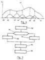
- FIG. 4represents an example of compensation for an induced magnetization of metallic structures included in a building using several loops ("V", "T” and / or "L").
- the buildingincludes five loops between its bow 40 and its stern 41.
- the circuit effects 42,43,44,45 and 46have the function of compensating for the magnetic signature 47 of the building.
- the 6,7,8 triaxial magnetometergives information relating to the magnetic fields measured on the three axes: transverse, longitudinal and vertical. This information is transmitted to a processing unit making it possible to obtain the currents I i to circulate in the different loops of the building 1, as just described.
- the compensation of the various components of the terrestrial magnetic fieldis carried out continuously according to the heading, the orientation and the inclination of the ship.
- FIG. 5is a flowchart representing the calculation method according to the invention for compensation of the magnetic field using k loops.
- the first manipulation 50 to be performedis to measure (EDC N ) i, that is to say the circuit effect of a loop i (with core) for all the loops included in a plan of the building comprising ferromagnetic structures of which compensate for the magnetizations.
- step 51is a test step consisting in asking the question if the coordinates of the center, the dimension and the location of the loop i are known.
- step 52consists in calculating (EDC A ) i that is to say the circuit effect of the loop i without nucleus, for example with the law of Biot and Savart and the current Io i .
- step 53consists in approximating the geometry of the loop i so that the correlation coefficient between (EDC N ) i measured and (EDC A ) i calculated, is 1.
- EDC Athe correlation coefficient between (EDC N ) i measured and (EDC A ) i calculated, is 1.
- step 54consists in calculating the induced magnetic field IM in the following considered plane: for all k loops located in the same plane ("L", "V” or "T").
- step 55consists in calculating the currents I i to be passed through the k loops by minimization of to compensate for the induced magnetic field IM in the plane considered.
Landscapes
- Engineering & Computer Science (AREA)
- Aviation & Aerospace Engineering (AREA)
- Geophysics And Detection Of Objects (AREA)
- Measuring Magnetic Variables (AREA)
- Measurement And Recording Of Electrical Phenomena And Electrical Characteristics Of The Living Body (AREA)
Abstract
Description
Translated fromFrenchLa présente invention se rapporte aux procédés permettant de compenser automatiquement les aimantations induites par le champ magnétique terrestre dans des structures en matériaux ferromagnétiques.The present invention relates to methods for automatically compensating the magnetizations induced by the earth's magnetic field in structures made of ferromagnetic materials.
Plus particulièrement, la présente invention concerne un procédé de calcul des effets de circuit dus aux aimantations verticales, transversales et longitudinales dans des structures ferromagnétiques.More particularly, the present invention relates to a method for calculating circuit effects due to vertical, transverse and longitudinal magnetizations in ferromagnetic structures.
Il est connu que la présence de matériaux ferromagnétiques dans un bâtiment naval rend ce bâtiment détectable par des moyens de détection de sa "signature magnétique" pouvant être intégrés par exemple dans des mines ou dans d'autres bâtiments navals.It is known that the presence of ferromagnetic materials in a naval vessel makes this vessel detectable by means of detecting its "magnetic signature" which can be integrated, for example, in mines or in other naval vessels.
La "signature magnétique" d'un bâtiment est constituée par son aimantation permanente et par son aimantation induite.The "magnetic signature" of a building is constituted by its permanent magnetization and by its induced magnetization.
L'aimantation permanente d'une structure est due aux matériaux ferromagnétiques la constituant. Celle-ci est sensiblement constante, ne fluctue qu'avec le temps et est liée à la nature du matériau utilisé.The permanent magnetization of a structure is due to the ferromagnetic materials constituting it. This is substantially constant, fluctuates only over time and is linked to the nature of the material used.
L'aimantation induite, en revanche, est essentiellement variable. Dans le cas d'un navire, elle dépend de son orientation dans le champ terrestre, de son cap et de son inclinaison due au roulis et au tangage.The induced magnetization, on the other hand, is essentially variable. In the case of a ship, it depends on its orientation in the land field, its course and its inclination due to roll and pitch.
La signature magnétique du navire permet donc de le repérer, de le suivre, et éventuellement de guider ou de mettre à feu des engins destinés à le détruire. Il est donc très important de minimiser, voire d'annuler cette "signature magnétique" pour empêcher sa détection par méthode magnétique.The magnetic signature of the ship therefore makes it possible to locate it, to follow it, and possibly to guide or ignite devices intended to destroy it. It is therefore very important to minimize or even cancel this "magnetic signature" to prevent its detection by magnetic method.
Cette opération, dite "immunisation magnétique", s'effectue. de manière connue, en créant dans le volume du bâtiment un champ magnétique qui compense celui du bâtiment, afin d'annuler sa signature magnétique. Pour cela, on munit le bâtiment d'un jeu de circuits appelés "boucles d'immunisation" qui sont parcourues par des courants électriques.This operation, called "magnetic immunization", is carried out. in known manner, by creating in the volume of the building a magnetic field which compensates for that of the building, in order to cancel its magnetic signature. For this, the building is provided with a set of circuits called "immunization loops" which are traversed by electric currents.
Les dimensions, la disposition des boucles et les courants qui y circulent sont déterminés pour minimiser au mieux la "signature magnétique" du bâtiment, quelle que soit son orientation dans le champ magnétique terrestre, c'est-à-dire quels que soient son cap et son inclinaison due au roulis et au tangage. Ces boucles d'immunisation sont réparties suivant trois directions correspondants aux axes de roulis, de lacet et de tangage, appelés de manière conventionnelle "L,M,A" ou encore "L,V,T" (Longitudinal, Vertical, Transversal).Dimensions, arrangement of loops and currents flowing therein are determined to best minimize the "magnetic signature" of the building, whatever its orientation in the earth's magnetic field, that is to say whatever its heading and its inclination due to roll and pitch. These immunization loops are distributed in three directions corresponding to the roll, yaw and pitch axes, conventionally called "L, M, A" or even "L, V, T" (Longitudinal, Vertical, Transversal).
Une station de mesure magnétique est utilisée pour déterminer les courants à faire circuler dans les boucles d'immunisation. Cette station mesure la signature magnétique du bâtiment et comporte par exemple deux réseaux linéaires de capteurs magnétiques. Ces réseaux sont installés au fond de la mer et alignés par exemple l'un selon une direction Nord-Sud et l'autre selon une direction Est-Ouest. Une station installée à terre analyse les mesures effectuées afin de déterminer les courants à faire circuler dans les différentes boucles ainsi que leur polarité.A magnetic measuring station is used to determine the currents to be circulated in the immunization loops. This station measures the building's magnetic signature and includes, for example, two linear arrays of magnetic sensors. These networks are installed at the bottom of the sea and aligned for example one in a North-South direction and the other in an East-West direction. A station installed on land analyzes the measurements made in order to determine the currents to be circulated in the different loops as well as their polarity.
Comme l'aimantation permanente est constante quelle que soit la position du navire et son cap, le courant à faire circuler dans chaque boucle pour compenser l'aimantation permanente est constant.As the permanent magnetization is constant whatever the position of the ship and its course, the current to be circulated in each loop to compensate for the permanent magnetization is constant.
Par contre, l'aimantation induite est variable et il est nécessaire de superposer aux courants déjà calculés une autre composante variable, déterminée selon le cap et la latitude du bâtiment, obtenus par exemple par des moyens de mesure gyroscopiques ou optiques.On the other hand, the induced magnetization is variable and it is necessary to superimpose on the currents already calculated another variable component, determined according to the heading and the latitude of the building, obtained for example by gyroscopic or optical measurement means.
L'aimantation totale (permanente + induite) s'écrit :
où :
P est l'aimantation permanente,
I est l'aimantation induite,
L, V et T sont les trois axes suivant lesquels sont disposées les boucles d'immunisation,
Θ représente le cap magnétique du navire.The total magnetization (permanent + induced) is written:
or :
P is the permanent magnetization,
I is the induced magnetization,
L, V and T are the three axes along which the immunization loops are arranged,
Θ represents the magnetic heading of the ship.
La station de mesure doit déterminer ces six composantes. Pour cela, le bâtiment parcourt deux fois le même trajet au-dessus des réseaux de capteurs magnétiques selon des caps opposés. L'aimantation permanente, liée au bâtiment, tourne avec celui-ci, alors que l'aimantation induite ne tourne pas. Pour connaître l'aimantation induite, il suffit de soustraire les résultats de mesure des deux sens opposés. Connaissant alors l'aimantation induite et l'aimantation totale, on obtient directement l'aimantation permanente. Ainsi, un passage Nord-Sud puis Sud-Nord permet de déterminer IL et un passage Est-Ouest puis Ouest-Est permet de calculer IT.The measurement station must determine these six components. For this, the building travels twice the same route over the networks of magnetic sensors in opposite directions. Permanent magnetization, linked to the building, rotates with it, while the induced magnetization does not rotate. To know the induced magnetization, it suffices to subtract the measurement results from the two opposite directions. Knowing then the induced magnetization and the total magnetization, the permanent magnetization is obtained directly. Thus, a North-South then South-North passage makes it possible to determine IL and an East-West then West-East passage makes it possible to calculate IT.
Cependant, cette méthode de mesure ne permet pas de déterminer IV.However, this measurement method does not allow IV to be determined.
La détermination de l'aimantation induite verticale est alors réalisée par des méthodes empiriques. Une de ces méthodes, utilisée dans la plupart des cas, consiste à considérer que l'aimantation induite verticale représente un certain pourcentage fixe de l'aimantation totale verticale mesurée dans un lieu donné.The determination of the vertical induced magnetization is then carried out by empirical methods. One of these methods, used in most cases, consists in considering that the vertical induced magnetization represents a certain fixed percentage of the total vertical magnetization measured in a given place.
Cependant, cette méthode reste très approximative. De plus, certains endroits du bâtiment sont plus magnétiques que d'autres, de par la présence de machines, de moteurs, propulseurs, etc..., faussant ainsi les résultats de cette méthode d'appréciation.However, this method remains very approximate. In addition, some places in the building are more magnetic than others, due to the presence of machines, motors, propellants, etc., thus distorting the results of this assessment method.
Une autre méthode consiste à effectuer ces réglages à deux reprises, à deux latitudes très différentes, et de réaliser des approximations sur les différences de mesures.Another method is to make these adjustments twice, at two very different latitudes, and to approximate the differences in measurements.
Cette méthode présente l'inconvénient de nécessiter un long et coûteux déplacement maritime pour les bâtiments navals à immuniser magnétiquement, et suppose que tout reste égal par ailleurs.This method has the drawback of requiring a long and costly maritime journey for the naval vessels to be magnetically immunized, and supposes that everything remains equal elsewhere.
C'est pourquoi une troisième méthode est également utilisée, consistant à simuler localement un environnement de champ magnétique différent du champ magnétique terrestre et d'effectuer la différence des mesures obtenues. Cette méthode ne nécessite pas de lointain déplacement, mais implique la mise en oeuvre de dispositifs très coûteux destinés à créer ce champ magnétique différent dans l'environnement de tout un bâtiment naval.This is why a third method is also used, consisting in locally simulating a magnetic field environment different from the terrestrial magnetic field and in performing the difference of the measurements obtained. This method does not require distant displacement, but involves the implementation of very expensive devices intended to create this different magnetic field in the environment of an entire naval ship.
L'invention a notamment pour but de remédier aux inconvénients évoqués précédemment.The object of the invention is in particular to remedy the drawbacks mentioned above.
Plus précisément, un premier objectif de l'invention est d'appliquer. à des bâtiments navals à structures ferromagnétiques, un procédé permettant un calcul de compensation non empirique de l'aimantation verticale induite sans infrastructure particulière.More specifically, a first objective of the invention is to apply. to naval vessels with ferromagnetic structures, a method allowing a calculation non-empirical compensation for the vertical magnetization induced without any particular infrastructure.
Un deuxième objectif de l'invention est de pouvoir appliquer ce calcul à la compensation des aimantations induites dans les plans horizontaux et transversaux.A second objective of the invention is to be able to apply this calculation to the compensation of the magnetizations induced in the horizontal and transverse planes.
Un troisième objectif de l'invention est de permettre le calcul d'une telle compensation sans nécessiter un lointain déplacement du bâtiment naval et à faible coût.A third objective of the invention is to allow the calculation of such compensation without requiring a distant displacement of the naval vessel and at low cost.
Un quatrième objectif de l'invention est de calculer l'aimantation à compenser que l'on connaisse ou non la position et la forme des boucles d'immunisation comprises dans un bâtiment naval.A fourth objective of the invention is to calculate the magnetization to compensate whether or not we know the position and the shape of the immunization loops included in a naval vessel.
Ces objectifs, ainsi que d'autres qui apparaîtront par la suite sont atteints grâce à un procédé de compensation automatique des aimantations induites par une composante directionnelle du champ magnétique terrestre dans une structure ferromagnétique, notamment un bâtiment naval, consistant à faire circuler des courants de compensation dans au moins une boucle d'immunisation située dans un plan sensiblement perpendiculaire à ladite composante directionnelle, caractérisé en ce qu'il comporte les étapes suivantes :
- obtention, par mesure, de l'effet de circuit (EDCN)i de chacune desdites boucles d'immunisation avec noyau, à une hauteur connue Ho et pour un courant de référence donné (Ici);
- obtention, par calcul, pour chacune desdites boucles (i), de son effet de circuit (EDCA)i en boucle à air, à la hauteur Ho, pour le même courant de référence Ici;
- calcul des courants (Ioi) à injecter dans chacune desdites boucles d'immunisation (i) pour que la somme de leurs effets de circuit en boucle à air soit égale, au niveau de ladite structure à compenser, à ladite composante directionnelle du champ magnétique à compenser;
- calcul pour l'injection des courants de référence Ioi, du champ magnétique (IM) dû à ladite aimantation induite suivant l'axe considéré d'après la formule:

- optimisation, par le calcul, des courants li à faire circuler dans les (k) boucles entourant lesdites structures ferromagnétiques pour compenser le champ magnétique induit IM dans le plan considéré.
- injection dans lesdites boucles (k) des courants Ii ainsi optimisés.

- obtaining, by measurement, the circuit effect (EDCN )i of each of said immunization loops with core, at a known height Ho and for a given reference current (Ici );
- obtaining, by calculation, for each of said loops (i), its circuit effect (EDCA )i in an air loop, at the height Ho, for the same reference current Ici ;
- calculation of the currents (Ioi ) to be injected into each of said immunization loops (i) so that the sum of their air loop circuit effects is equal, at the level of said structure to be compensated, to said directional component of the magnetic field to compensate;
- calculation for the injection of the reference currents Ioi , of the magnetic field (IM) due to said magnetization induced along the axis considered according to the formula:
- optimization, by calculation, of the currents li to be circulated in the (k) loops surrounding said ferromagnetic structures to compensate for the induced magnetic field IM in the plane considered.
- injection into said loops (k) of currents Ii thus optimized.
Préférentiellement, le calcul de l'effet de circuit d'une boucle à air (EDCA) à la hauteur Ho, dans le cas où les dimensions et coordonnées de ladite boucle sont connues, est effectué par la loi de Biot et Savart avec le courant Ic.Preferably, the calculation of the circuit effect of an air loop (EDCA ) at the height Ho, in the case where the dimensions and coordinates of said loop are known, is carried out by the law of Biot and Savart with the current Ic.
Avantageusement, dans le cas où les dimensions et coordonnées d'une boucle ne sont pas connues, le calcul de l'effet de circuit en boucle à air (EDCA)i de ladite boucle d'immunisation (i), à la hauteur Ho, est effectué en supposant que ladite boucle de dimensions et coordonnées inconnues est équivalente à une boucle de géométrie simple donnée, par exemple de type polygonal ou elliptique, et en optimisant les dimensions, les coordonnées et le courant de ladite boucle équivalente de façon que le coefficient de corrélation entre l'effet de circuit mesuré pour ladite boucle de dimensions et coordonnées inconnues soit le plus grand possible.Advantageously, in the case where the dimensions and coordinates of a loop are not known, the calculation of the air loop circuit effect (EDCA )i of said immunization loop (i), at the height Ho , is performed by supposing that said loop of unknown dimensions and coordinates is equivalent to a loop of given simple geometry, for example of polygonal or elliptical type, and by optimizing the dimensions, coordinates and current of said equivalent loop so that the correlation coefficient between the circuit effect measured for said loop of unknown dimensions and coordinates is as large as possible.
Selon un mode de mise en oeuvre préférentiel de l'invention, ledit calcul des courants (Ioi) constitue une optimisation, notamment au sens des moindres carrés, d'un champ équivalent à un champ généré par une boucle fictive entourant un bâtiment naval comprenant lesdites structures, dont le courant est tel que le champ au centre de ce circuit est égal à la composante directionnelle du champ magnétique terrestre à compenser.According to a preferred embodiment of the invention, said calculation of the currents (Ioi ) constitutes an optimization, in particular in the least squares sense, of a field equivalent to a field generated by a fictitious loop surrounding a naval vessel comprising said structures, the current of which is such that the field at the center of this circuit is equal to the directional component of the terrestrial magnetic field to be compensated.
Préférentiellement, l'optimisation des courants (Ii) à faire circuler dans les (k) boucles entourant lesdites structures ferromagnétiques est réalisée par minimisation de:
et par l'envoi des courants (Ii) dans les boucles de compensation (i) entourant lesdites structures.Preferably, the optimization of the currents (Ii ) to be circulated in the (k) loops surrounding said ferromagnetic structures is carried out by minimization of:
and by sending the currents (Ii ) into the compensation loops (i) surrounding said structures.
Avantageusement, le procédé est appliqué à la compensation des aimantations induites dans les directions verticale, transversale et/ou longitudinale.Advantageously, the method is applied to the compensation of the magnetizations induced in the vertical, transverse and / or longitudinal directions.
D'autres caractéristiques et avantages de l'invention apparaîtront à la lecture de la description suivante d'un mode de mise en oeuvre préférentiel de l'invention, donné à titre illustratif et non limitatif, et des dessins annexés dans lesquels :
- la figure 1 représente les trois directions de disposition des boucles d'immunisation dans un navire ;
- la figure 2A représente l'effet de circuit d'une boucle avec noyau;
- la figure 2B représente l'effet de circuit de la même boucle sans noyau;
- la figure 3A représente un exemple de disposition de boucles "V" dans un navire
- la figure 3B représente une coupe selon AA de la figure 3A ;
- la figure 4 représente une compensation d'une aimantation induite de structures métalliques à l'aide de plusieurs boucles.
- la figure 5 est un organigramme représentant le procédé de calcul selon l'invention pour une compensation du champ magnétique à l'aide de k boucles.
- FIG. 1 represents the three directions of arrangement of the immunization loops in a ship;
- FIG. 2A represents the circuit effect of a loop with core;
- Figure 2B shows the circuit effect of the same coreless loop;
- FIG. 3A represents an example of arrangement of loops "V" in a ship
- FIG. 3B represents a section along AA of FIG. 3A;
- FIG. 4 represents a compensation for an induced magnetization of metallic structures using several loops.
- FIG. 5 is a flowchart representing the calculation method according to the invention for compensation of the magnetic field using k loops.
La figure 1 représente les trois directions de disposition des boucles d'immunisation dans un bâtiment naval.FIG. 1 represents the three directions of arrangement of the immunization loops in a naval vessel.
Le bâtiment 1 comprend des structures ferromagnétiques entourées par des boucles 2, 3, 4 d'immunisation. Ces boucles sont disposées dans trois plans distincts. Une boucle 2 sert à compenser l'aimantation longitudinale et est couramment appelée boucle "L", une autre boucle 3 sert à compenser l'aimantation verticale et est notée "V" et la troisième boucle 4 qui a pour fonction de compenser l'aimantation transversale est notée "T".Building 1 includes ferromagnetic structures surrounded by
Une boucle est caractérisée par ses coordonnées (x,y,z) par rapport à un point donné, par ses dimensions, par sa résistance, par sa forme, par le courant maximal pouvant la traverser, et par le nombre de tours disponibles.A loop is characterized by its coordinates (x, y, z) relative to a given point, by its dimensions, by its resistance, by its shape, by the maximum current that can cross it, and by the number of available turns.
Bien entendu, la disposition de la figure 1 n'est qu'indicative, l'immunisation de toutes les structures ferromagnétiques comprises dans un navire impliquant la disposition de nombreuses boucles dans les différents plans autour des structures à compenser.Of course, the arrangement of Figure 1 is only indicative, immunization of all the ferromagnetic structures included in a ship implying the provision of numerous loops in the different planes around the structures to be compensated.
La présente invention a notamment pour objectif de compenser l'aimantation induite verticale à l'aide d'au moins une boucle "V" 3 disposée dans un plan parallèle à la surface de flottaison du bâtiment 1.The object of the present invention is in particular to compensate for the vertical induced magnetization by means of at least one "V"
On explique maintenant le principe du procédé.We now explain the principle of the process.
La figure 2A représente l'effet de circuit d'une boucle avec noyau ferromagnétique noté EDCN. Une structure ferromagnétique 20 est entourée par une seule boucle 22 dont le centre 21 est également le barycentre de la structure.FIG. 2A represents the circuit effect of a loop with ferromagnetic core denoted EDCN. A
Un effet de circuit est une mesure de la différence des champs magnétiques mesurés avec le circuit alimenté d'une part et le circuit non alimenté d'autre part.A circuit effect is a measure of the difference between the magnetic fields measured with the powered circuit on the one hand and the unpowered circuit on the other.
L'effet de circuit de la boucle 22 est mesuré pour un courant continu Ic 23 d'intensité connue et on obtient une courbe 25 représentative du vecteur 24 de champ magnétique lié à l'aimantation induite dans le noyau par la boucle 22.The circuit effect of
Pour obtenir le champ magnétique dû à l'aimantation induite dans la structure 20 par la boucle 22, il faut connaître l'effet de circuit de la boucle 22 seule, sans le noyau 20, noté EDCA. Une telle boucle est appelée boucle à air.To obtain the magnetic field due to the magnetization induced in the
La figure 2B représente l'effet de circuit d'une boucle à air. Deux cas sont à considérer : si les coordonnées et dimensions de la boucle sont connues, on reprend exactement cette boucle et on calcule son effet de circuit sans noyau. Si les caractéristiques de la boucle sont inconnues, on optimise les caractéristiques d'une boucle à géométrie simple.Figure 2B shows the circuit effect of an air loop. Two cases are to be considered: if the coordinates and dimensions of the loop are known, this loop is taken up exactly and its kernel circuit effect is calculated. If the characteristics of the loop are unknown, we optimize the characteristics of a simple geometry loop.
Dans le cas où les coordonnées et les dimensions de la boucle sont connues, on calcule l'effet de circuit de la boucle sans noyau, cet effet de circuit ne pouvant être mesuré. On le calcule donc en connaissant la géométrie de la boucle 22, sa position dans le bâtiment pour le courant Ic 23 et la distance à laquelle la mesure de l'effet de circuit de la boucle avec noyau a été effectuée.In the case where the coordinates and dimensions of the loop are known, the circuit effect of the coreless loop is calculated, this circuit effect cannot be measured. It is therefore calculated by knowing the geometry of the
Ce calcul est par exemple effectué au moyen de la loi de Biot et Savart, permettant d'obtenir l'effet de circuit 26 de la boucle à air recherché, soit
Le champ magnétique à compenser est égal à la différence entre l'effet de circuit mesuré avec la structure à compenser et l'effet de circuit de la boucle à air.The magnetic field to be compensated is equal to the difference between the circuit effect measured with the structure to be compensated and the circuit effect of the air loop.
Pour obtenir ce champ, de manière à ce qu'il soit égal à celui créé par la composante verticale du champ magnétique terrestre, il suffit d'injecter un courant Io tel que l'effet de circuit de la boucle à air soit égal, au niveau de la structure à compenser, à la composante verticale du champ magnétique terrestre. On approxime alors le champ magnétique induit vertical noté IVM par :
Le champ magnétique induit par le courant Io circulant dans la boucle 22 entourant la structure 20 à compenser, compense donc le champ magnétique terrestre et rend la structure ferromagnétique invisible aux systèmes de détection basés sur ce principe, en créant dans l'environnement de la structure un champ magnétique total approximativement nul.The magnetic field induced by the current Io circulating in the
Cette approximation est d'autant plus exacte que la boucle est grande par rapport à la structure à compenser.This approximation is all the more exact as the loop is large compared to the structure to compensate.
Dans le cas où les coordonnées et les dimensions de la boucle ne sont pas connues, par exemple dans le cas de bâtiments anciens dont on ne dispose pas de plans précis indiquant la disposition des boucles existantes, il est nécessaire d'approximer la taille et les coordonnées de cette boucle. L'effet de circuit de la boucle à air est alors estimé en supposant que son effet de circuit mesuré avec noyau est équivalent à l'effet de circuit du même circuit sans noyau, mais avec un courant d'intensité différente. On admet également que la boucle peut être réduite à une boucle de géométrie simple, par exemple polygonale ou elliptique.In the case where the coordinates and dimensions of the loop are not known, for example in the case of old buildings for which there are no precise plans indicating the arrangement of the existing loops, it is necessary to approximate the size and the coordinates of this loop. The air loop circuit effect is then estimated by assuming that its measured circuit effect with core is equivalent to the circuit effect of the same circuit without core, but with a current of different intensity. It is also admitted that the loop can be reduced to a loop of simple geometry, for example polygonal or elliptical.
Les paramètres de la boucle à air, à savoir l'intensité du courant IcA, les coordonnées du centre et les dimensions sont optimisées de façon à reproduire le champ de l'effet de circuit (EDCN)Ic mesuré à une hauteur Ho pour un courant Ic connu. Cette optimisation consiste notamment à faire varier les coordonnées du centre de la boucle (x,y,z) et ses dimensions, de telle sorte que le coefficient de corrélation entre (EDCN)Ic mesuré et EDCA calculé soit de 1. Elle peut par exemple être réalisée par la méthode des moindres carrés.The parameters of the air loop, namely the intensity of the current IcA , the coordinates of the center and the dimensions are optimized so as to reproduce the field of the circuit effect (EDCN )Ic measured at a height Ho for a known current Ic. This optimization notably consists in varying the coordinates of the center of the loop (x, y, z) and its dimensions, so that the correlation coefficient between (EDCN )Ic measured and EDCA calculated is 1. It can for example be carried out by the method of least squares.
On obtient:
Puisque
il vient :
he comes :
On obtient également, par cette optimisation, la géométrie de la boucle et on se retrouve ramené au cas précédent pour obtenir le courant Io. Connaissant (EDCN)Ic, (EDCA)Ic, Io et Ic, on obtient l'IVM comme précédemment.We also obtain, by this optimization, the geometry of the loop and we find ourselves brought back to the previous case to obtain the current Io. Knowing (EDCN )Ic , (EDCA )Ic , Io and Ic, we obtain the IVM as before.
Comme indiqué précédemment, un bâtiment naval comporte plusieurs boucles d'immunisation, notamment des boucles "V" et la figure 3A représente un exemple de dispositions de boucles "V" dans un navire.As indicated above, a naval vessel has several immunization loops, in particular "V" loops and FIG. 3A shows an example of arrangements of "V" loops in a ship.
Les boucles d'immunisation 31,32,33,34,35 sont situées à différentes hauteurs dans le navire 30. La boucle 36 est une boucle fictive représentant l'ensemble des boucles 31 à 35. Dans la suite de la description, i est l'indice se rapportant à une boucle.The
Les effets de circuits (EDCN)i sont mesurés sur station lors des réglages du bateau pour des courants Ici et pour les circuits dans le plan horizontal.The effects of circuits (EDCN )i are measured on station when the boat is adjusted for currents Ici and for circuits in the horizontal plane.
S'il y a k circuits "V", d'après les enseignements précédents, le champ IVM vaut :
Puisque (EDCN)i et Ici sont connus, il reste à calculer EDC

Since (EDCN )i and Ici are known, it remains to calculate EDC
Si l'implantation et la géométrie des boucles "V" sont connus, les (EDCA)i sont calculés comme décrit précédemment. Les courants Ioi sont calculés en optimisant, au sens des moindres carrés par exemple, ces courants pour générer avec les boucles à air un champ équivalent au champ généré par la boucle fictive 36 entourant le bâtiment parcourue par un courant tel qu'il crée au centre un champ égal à la composante verticale du champ terrestre. La position verticale de cette boucle 36 est située préférentiellement au barycentre magnétique des pièces ferromagnétiques ou bien si cette position est inconnue à la moyenne des hauteurs des circuits "V" ou bien encore à la ligne de flottaison pour un bateau de surface.If the location and the geometry of the loops "V" are known, the (EDCA )i are calculated as described above. The currents Ioi are calculated by optimizing, in the least squares sense for example, these currents to generate with the air loops a field equivalent to the field generated by the
Si l'implantation et la géométrie des boucles "V" ne sont pas connues, les (EDCA)i sont obtenus comme décrit précédemment ainsi que les Ioi en se ramenant au cas précédent.If the location and the geometry of the loops "V" are not known, the (EDCA )i are obtained as described above as well as the Ioi by reducing to the previous case.
Le champ magnétique induit vertical IVM étant obtenu, les courants Ii à faire passer dans les boucles sont obtenus par exemple par minimisation de :
Le procédé peut être étendu aux compensations des champs induits transversal ("T") et longitudinal ("L") en appliquant l'invention aux circuits d'immunisation dans le plan vertical suivant l'axe du bâtiment et aux circuits d'immunisation dans les plans verticaux perpendiculaires à l'axe du bâtiment.The process can be extended to compensate for the transverse ("T") and longitudinal ("L") induced fields by applying the invention to the immunization circuits in the vertical plane along the axis of the building and to the immunization circuits in vertical planes perpendicular to the axis of the building.
Le réglage de tous les circuits d'immunisation ne nécessite donc plus qu'un seul passage du bâtiment à un cap quelconque connu.The adjustment of all the immunization circuits therefore requires only a single passage from the building to any known heading.
La figure 4 représente un exemple de compensation d'une aimantation induite de structures métalliques comprises dans un bâtiment à l'aide de plusieurs boucles ("V", "T" et/ou "L").FIG. 4 represents an example of compensation for an induced magnetization of metallic structures included in a building using several loops ("V", "T" and / or "L").
Le bâtiment comprend sur cet exemple cinq boucles entre sa proue 40 et sa poupe 41. Les effets de circuit 42,43,44,45 et 46 ont pour fonction de compenser la signature magnétique 47 du bâtiment.In this example, the building includes five loops between its
Comme les champs magnétiques induits dans les structures ferromagnétiques évoluent avec le cap du bâtiment et sa situation géographique, il est nécessaire de compenser de façon continue ces champs magnétiques qu'ils soient longitudinaux, transversaux ou verticaux.As the magnetic fields induced in ferromagnetic structures evolve with the heading of the building and its geographical location, it is necessary to continuously compensate for these magnetic fields whether they are longitudinal, transverse or vertical.
C'est pourquoi le bâtiment en question est équipé, fixé sur un mât 5 rigide et solidaire du bâtiment 1, d'un magnétomètre triaxial 6,7,8 suffisamment éloigné du bâtiment pour que celui-ci n'ait pas d'influence sur les mesures effectuées.This is why the building in question is equipped, fixed on a rigid mast 5 and integral with building 1, of a
Le magnétomètre triaxial 6,7,8 donne des informations relatives aux champs magnétiques mesurés sur les trois axes : transversal, longitudinal et vertical. Ces informations sont transmises à une unité de traitement permettant d'obtenir les courants Ii à faire circuler dans les différentes boucles du bâtiment 1, comme il vient d'être décrit.The 6,7,8 triaxial magnetometer gives information relating to the magnetic fields measured on the three axes: transverse, longitudinal and vertical. This information is transmitted to a processing unit making it possible to obtain the currents Ii to circulate in the different loops of the building 1, as just described.
Ainsi, la compensation des différentes composantes du champ magnétique terrestre est réalisée de façon continue en fonction du cap, de l'orientation et de l'inclinaison du navireThus, the compensation of the various components of the terrestrial magnetic field is carried out continuously according to the heading, the orientation and the inclination of the ship.
Il va de soi, que plus le nombre de boucles est élevé, meilleure sera la compensation et que cette compensation impose la connaissance des différents effets de circuit de chacune des boucles.It goes without saying that the higher the number of loops, the better the compensation and that this compensation requires knowledge of the different circuit effects of each of the loops.
La figure 5 est un organigramme représentant le procédé de calcul selon l'invention pour une compensation du champ magnétique à l'aide de k boucles.FIG. 5 is a flowchart representing the calculation method according to the invention for compensation of the magnetic field using k loops.
La première manipulation 50 à effectuer est de mesurer (EDCN)i c'est à dire l'effet de circuit d'une boucle i (avec noyau) pour toutes les boucles comprises dans un plan du bâtiment comprenant des structures ferromagnétiques dont on veut compenser les aimantations.The
Cette mesure de (EDCN)i est réalisée pour un courant Ici donné.This measurement of (EDCN )i is carried out for a given current Ici .
L'étape 51 suivante est une étape de test consistant à poser la question si les coordonnées du centre, la dimension et l'implantation de la boucle i sont connues.The following
Si la réponse est oui, l'étape 52 consiste à calculer (EDCA)i c'est à dire l'effet de circuit de la boucle i sans noyau, par exemple avec la loi de Biot et Savart et le courant Ioi.If the answer is yes, step 52 consists in calculating (EDCA )i that is to say the circuit effect of the loop i without nucleus, for example with the law of Biot and Savart and the current Ioi .
Si la réponse est non, l'étape 53 consiste à approximer la géométrie de la boucle i de telle sorte que le coefficient de corrélation entre (EDCN)i mesuré et (EDCA)i calculé, soit de 1. On obtient (EDCA)i puis Ioi.If the answer is no, step 53 consists in approximating the geometry of the loop i so that the correlation coefficient between (EDCN )i measured and (EDCA )i calculated, is 1. We obtain (EDCA )i then Ioi .
Une fois (EDCA)i calculé, l'étape 54 consiste à calculer le champ magnétique induit IM dans le plan considéré suivant :
pour toutes les k boucles se trouvant dans un même plan ("L", "V" ou "T").Once (EDCA )i has been calculated,
for all k loops located in the same plane ("L", "V" or "T").
L'étape 55 suivante consiste à calculer les courants Ii à faire passer dans les k boucles par minimisation de
pour compenser le champ magnétique induit IM dans le plan considéré.The following
to compensate for the induced magnetic field IM in the plane considered.
De nombreuses autres applications de l'invention sont envisageables, qui apparaîtront aisément à l'homme de métier.Many other applications of the invention are conceivable, which will readily appear to those skilled in the art.
Claims (6)
- Method for automatically compensating the magnetization induced by a directional component of the Earth's magnetic field in a ferromagnetic structure, particularly a naval ship, consisting in causing compensating currents to flow in at least one immunization loop located in a plane substantially perpendicular to the said directional component, characterized in that it comprises the following steps:- obtaining, by measurement (50), the circuit effect (EDCN)i of each one of the said immunization loops with a core, at a known height Ho and for a given reference current (Ici);- obtaining, by computation (52, 53), for each of the said loops (i), its air-loop circuit effect (EDCA)i, at the height Ho, for the same reference current (Ici);- computation of the currents (Ioi) to be injected into each of the said immunization loops (i) such that the sum of their air-loop circuit effects is equal, at the level of the said structure to be compensated, to the said directional component of the magnetic field to be compensated;- computation (54) for the injection of the reference currents Ioi, of the magnetic field (IM) due to the said induced magnetization along the axis in question according to the formula:
 - optimization (55), by computation, of the currents Ii to be caused to flow in the (k) loops surrounding the said ferromagnetic structures in order to compensate the induced magnetic field IM in the plane in question; and- injection into the said loops (k) of the currents Ii thus optimized.
 - Method according to Claim 1, characterized in that the computation (52) of the circuit effect of an air loop (EDCA) at the height Ho, in the case in which the dimensions and coordinates of the said loop are known, is carried out according to the Biot and Savart law with the current Ic.
- Method according to Claim 1, characterized in that in the case in which the dimensions and coordinates of a loop are not known, the computation (53) of the air-loop circuit effect (EDCA)i of the said immunization loop (i), at the height Ho, is carried out assuming that the said loop of unknown dimensions and coordinates is equivalent to a given loop of simple geometry, for example of the polygonal or elliptical type, by computing the correlation factor between the measured circuit effect [(EDCN)Ic] of the said loop of unknown dimensions and coordinates and the air-loop circuit effect (EDCA)i of the said equivalent loop, and by optimising the dimensions, the coordinates and the current of the said equivalent loop such that the said correlation factor is as big as possible.
- Method according to any one of Claims 1 to 3, characterized in that the said computation of the currents (Ioi) constitutes an optimization, particularly in the sense of least squares, of a field equivalent to a field generated by an imaginary loop surrounding a naval ship comprising the said structures, whose current is such that the field at the centre of this circuit is equal to the directional component of the Earth's magnetic field to be compensated.
- Method according to Claim 1, characterized in that the optimization (55) of the currents (Ii) to be caused to flow in the (k) loops surrounding the said ferromagnetic structures is carried out by minimization of:

- Method according to any one of Claims 1 to 5, characterized in that it is applied to the compensation of magnetization induced in the vertical, transverse and/or longitudinal directions.


Applications Claiming Priority (2)
| Application Number | Priority Date | Filing Date | Title |
|---|---|---|---|
| FR9003383 | 1990-03-16 | ||
| FR9003383AFR2659787B1 (en) | 1990-03-16 | 1990-03-16 | METHOD FOR AUTOMATIC COMPENSATION OF MAGNETS INDUCED BY THE EARTH MAGNETIC FIELD IN FERROMAGNETIC MATERIALS, ESPECIALLY INCLUDED IN A NAVAL VESSEL. |
Publications (2)
| Publication Number | Publication Date |
|---|---|
| EP0472715A1 EP0472715A1 (en) | 1992-03-04 |
| EP0472715B1true EP0472715B1 (en) | 1993-12-22 |
Family
ID=9394815
Family Applications (1)
| Application Number | Title | Priority Date | Filing Date |
|---|---|---|---|
| EP19910906852Expired - LifetimeEP0472715B1 (en) | 1990-03-16 | 1991-03-15 | Process for automatically compensating the magnetization induced by the earth's magnetic field in ferromagnetic materials, especially those used in a naval ship |
Country Status (4)
| Country | Link |
|---|---|
| EP (1) | EP0472715B1 (en) |
| DE (1) | DE69100832T2 (en) |
| FR (1) | FR2659787B1 (en) |
| WO (1) | WO1991013801A1 (en) |
Cited By (1)
| Publication number | Priority date | Publication date | Assignee | Title |
|---|---|---|---|---|
| CN111009379A (en)* | 2019-11-18 | 2020-04-14 | 中国人民解放军海军潜艇学院 | Magnetic confinement method and self-demagnetizing naval vessel |
Families Citing this family (1)
| Publication number | Priority date | Publication date | Assignee | Title |
|---|---|---|---|---|
| FR2825803B1 (en)* | 2001-06-12 | 2003-08-22 | France Etat Armement | METHOD FOR DETERMINING THE MAGNET AND THE RADIUS FIELD BY A SHEET |
Family Cites Families (4)
| Publication number | Priority date | Publication date | Assignee | Title |
|---|---|---|---|---|
| FR1184512A (en)* | 1955-03-07 | 1959-07-22 | Le Ministre De La Defense Nati | Improvements made to means such as those for compensating for magnetic disturbances in ships |
| JPS60182706A (en)* | 1984-02-29 | 1985-09-18 | Shimadzu Corp | Determining method of optimum ampere-turn of coil |
| DE3614527A1 (en)* | 1986-04-29 | 1987-11-05 | Bundesrep Deutschland | METHOD FOR SETTING A MAGNETIC PROTECTION (MES) - SYSTEM FOR COMPENSATING THE MAGNETIC INTERFERENCE FIELD OF A VEHICLE, IN PARTICULAR SHIP |
| DE3620402A1 (en)* | 1986-06-18 | 1987-12-23 | Bundesrep Deutschland | DEVICE FOR CONTROLLING A MAGNETIC SELF-PROTECTION (MES) SYSTEM |
- 1990
- 1990-03-16FRFR9003383Apatent/FR2659787B1/ennot_activeExpired - Fee Related
- 1991
- 1991-03-15WOPCT/FR1991/000209patent/WO1991013801A1/enactiveIP Right Grant
- 1991-03-15DEDE91906852Tpatent/DE69100832T2/ennot_activeExpired - Fee Related
- 1991-03-15EPEP19910906852patent/EP0472715B1/ennot_activeExpired - Lifetime
Cited By (1)
| Publication number | Priority date | Publication date | Assignee | Title |
|---|---|---|---|---|
| CN111009379A (en)* | 2019-11-18 | 2020-04-14 | 中国人民解放军海军潜艇学院 | Magnetic confinement method and self-demagnetizing naval vessel |
Also Published As
| Publication number | Publication date |
|---|---|
| DE69100832T2 (en) | 1994-04-07 |
| DE69100832D1 (en) | 1994-02-03 |
| WO1991013801A1 (en) | 1991-09-19 |
| EP0472715A1 (en) | 1992-03-04 |
| FR2659787B1 (en) | 1994-08-26 |
| FR2659787A1 (en) | 1991-09-20 |
Similar Documents
| Publication | Publication Date | Title |
|---|---|---|
| EP1228386B1 (en) | Method for simulating streamer positioning, and for navigation aid | |
| Frew et al. | Air‐sea gas transfer: Its dependence on wind stress, small‐scale roughness, and surface films | |
| Graf et al. | Analysis of experimentally validated trans‐ionospheric attenuation estimates of VLF signals | |
| Kinrade et al. | GPS phase scintillation associated with optical auroral emissions: First statistical results from the geographic South Pole | |
| EP0583993B1 (en) | Measuring appliance and method at earth level for high voltage air lines | |
| EP3272119B1 (en) | Method and device of 3d reconstruction of a scene | |
| FR2478302A1 (en) | MAGNETIC COMPASS FOR A VEHICLE CONTAINING A LOT OF IRON | |
| EP0538129A1 (en) | Acoustic transmitting device for seismic marine surveying | |
| EP1868161A1 (en) | Method of determining the range of visibility for a driver of a vehicle | |
| WO2011154545A2 (en) | Method of deployment, method and device for seismic prospecting in an aquatic medium | |
| WO2017190951A1 (en) | Self-calibrating and autonomous magnetic observatory | |
| EP0777128A1 (en) | Method and device for attitude measurement of a satellite | |
| EP0011522A1 (en) | Positioning device for a moving body by way of a magnetic field | |
| EP0472715B1 (en) | Process for automatically compensating the magnetization induced by the earth's magnetic field in ferromagnetic materials, especially those used in a naval ship | |
| FR2981170A1 (en) | NONLINEAR TOMOGRAPHY METHOD FOR A MAIN SYMMETRY AXIS OF AN ANISOTROPIC SPEED MODEL AND DEVICE. | |
| EP0133408B1 (en) | System for determining the course of a marine structure | |
| EP2974431A1 (en) | Method for predicting the level of radio field and/or the duration of propagation of cellular telephone networks using high-resolution terrain databases | |
| EP0597014B1 (en) | Portable station for the measurement and adjustment of the magnetic signature of a naval vessel | |
| Sakai et al. | Storm time enhancements of 630.0 nm airglow associated with polar cap patches | |
| FR2922321A1 (en) | METHOD OF SIMULATING THE POSITIONING OF AT LEAST ONE STREAMER COMPRISING A STEP PREDICTING A CURRENT IN AT LEAST TWO SEPARATE POINTS OF THE STREAMER | |
| EP1395843B1 (en) | Method for determining magnetisation and the field radiated by a ferromagnetic plate | |
| Chu et al. | Morphological characteristics of strong thermal emission velocity enhancement emissions | |
| Tuttle et al. | Temporal and spatial evolution of auroral electron energy spectra in a region surrounding the magnetic zenith | |
| EP1666923A1 (en) | Procedure for locating mobile magnetic targets | |
| EP0591309A1 (en) | Method for automatically monitoring and controlling the degaussing of a naval vessel. |
Legal Events
| Date | Code | Title | Description |
|---|---|---|---|
| PUAI | Public reference made under article 153(3) epc to a published international application that has entered the european phase | Free format text:ORIGINAL CODE: 0009012 | |
| 17P | Request for examination filed | Effective date:19911015 | |
| AK | Designated contracting states | Kind code of ref document:A1 Designated state(s):DE GB SE | |
| 17Q | First examination report despatched | Effective date:19930402 | |
| 17Q | First examination report despatched | Effective date:19930517 | |
| GRAA | (expected) grant | Free format text:ORIGINAL CODE: 0009210 | |
| AK | Designated contracting states | Kind code of ref document:B1 Designated state(s):DE GB SE | |
| REF | Corresponds to: | Ref document number:69100832 Country of ref document:DE Date of ref document:19940203 | |
| RAP2 | Party data changed (patent owner data changed or rights of a patent transferred) | Owner name:THOMSON-CSF | |
| GBT | Gb: translation of ep patent filed (gb section 77(6)(a)/1977) | Effective date:19940225 | |
| PLBE | No opposition filed within time limit | Free format text:ORIGINAL CODE: 0009261 | |
| STAA | Information on the status of an ep patent application or granted ep patent | Free format text:STATUS: NO OPPOSITION FILED WITHIN TIME LIMIT | |
| 26N | No opposition filed | ||
| EAL | Se: european patent in force in sweden | Ref document number:91906852.8 | |
| PGFP | Annual fee paid to national office [announced via postgrant information from national office to epo] | Ref country code:SE Payment date:19980213 Year of fee payment:8 Ref country code:GB Payment date:19980213 Year of fee payment:8 | |
| PGFP | Annual fee paid to national office [announced via postgrant information from national office to epo] | Ref country code:DE Payment date:19980218 Year of fee payment:8 | |
| PG25 | Lapsed in a contracting state [announced via postgrant information from national office to epo] | Ref country code:GB Free format text:LAPSE BECAUSE OF NON-PAYMENT OF DUE FEES Effective date:19990315 | |
| PG25 | Lapsed in a contracting state [announced via postgrant information from national office to epo] | Ref country code:SE Free format text:LAPSE BECAUSE OF NON-PAYMENT OF DUE FEES Effective date:19990316 | |
| EUG | Se: european patent has lapsed | Ref document number:91906852.8 | |
| GBPC | Gb: european patent ceased through non-payment of renewal fee | Effective date:19990315 | |
| EUG | Se: european patent has lapsed | Ref document number:91906852.8 | |
| PG25 | Lapsed in a contracting state [announced via postgrant information from national office to epo] | Ref country code:DE Free format text:LAPSE BECAUSE OF NON-PAYMENT OF DUE FEES Effective date:20000101 |